
Fracturing in 14MoV6-3 Steel Weld Joints—Including Base Metals—After a Short Time in Service

 , , ,
, , ,
Abstract
1. Introduction
2. Materials and Methods
2.1. Materials
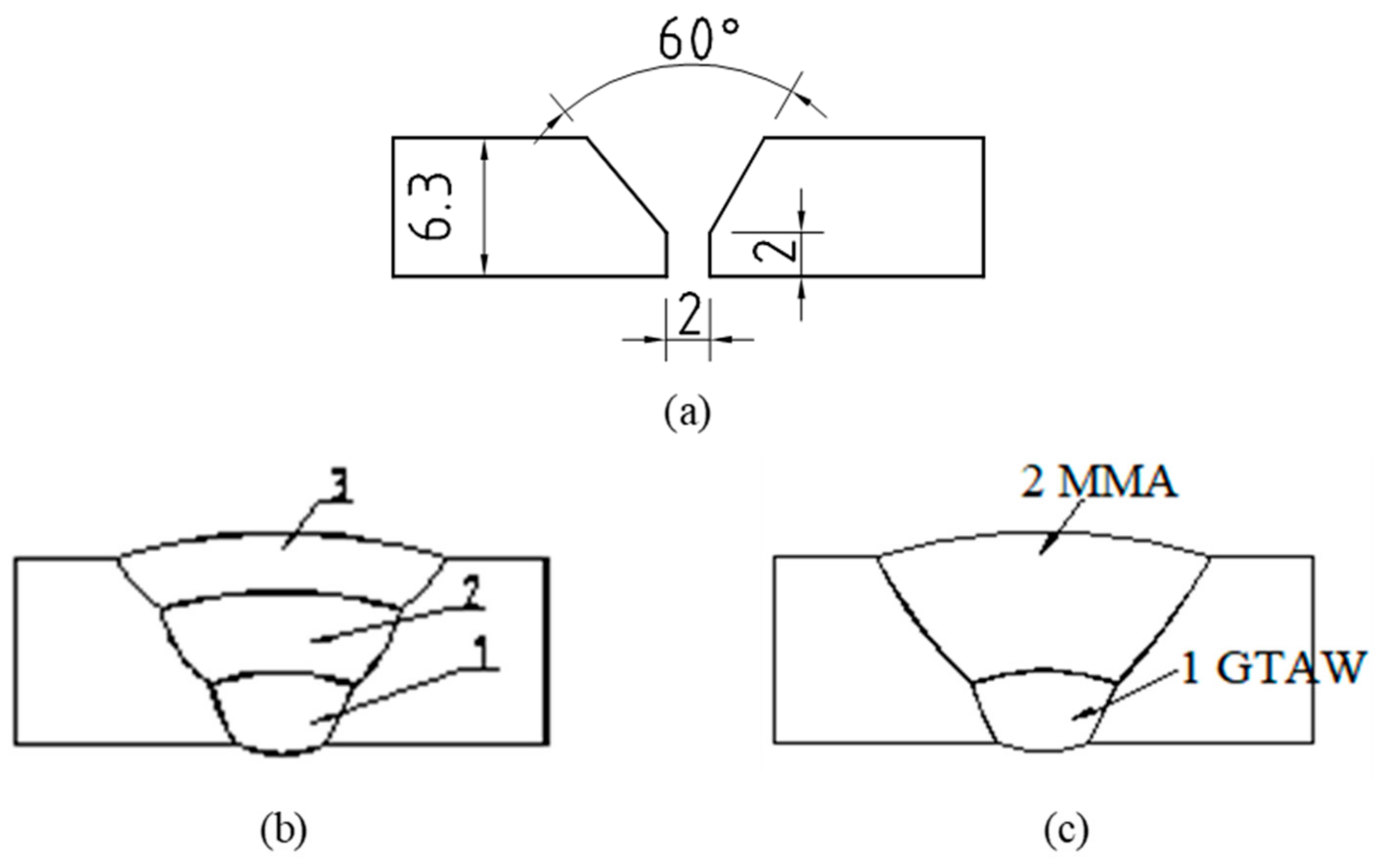
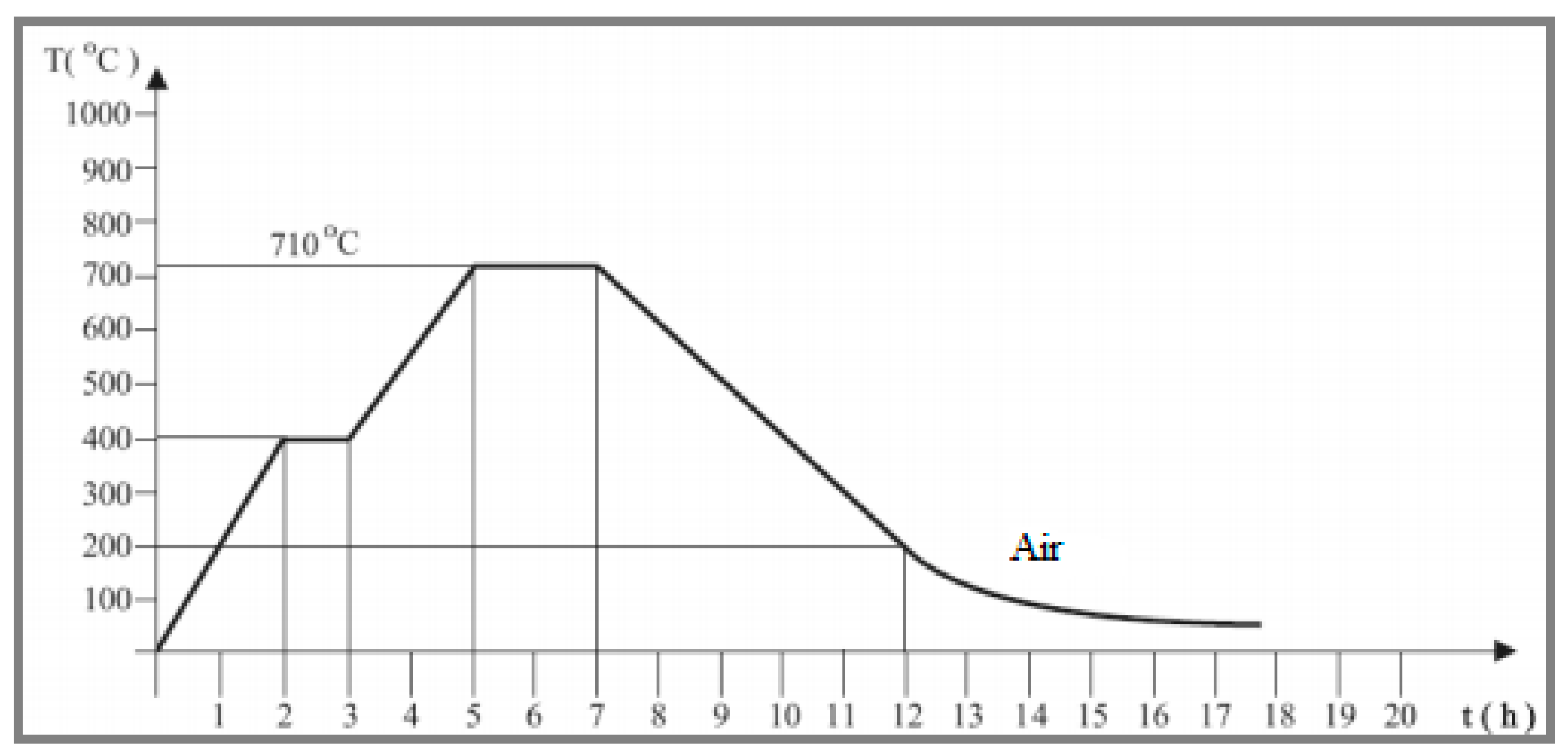
2.2. Welding
2.3. Testing of Welded Joints
2.4. Microstructure Examination
3. Results and Discussion
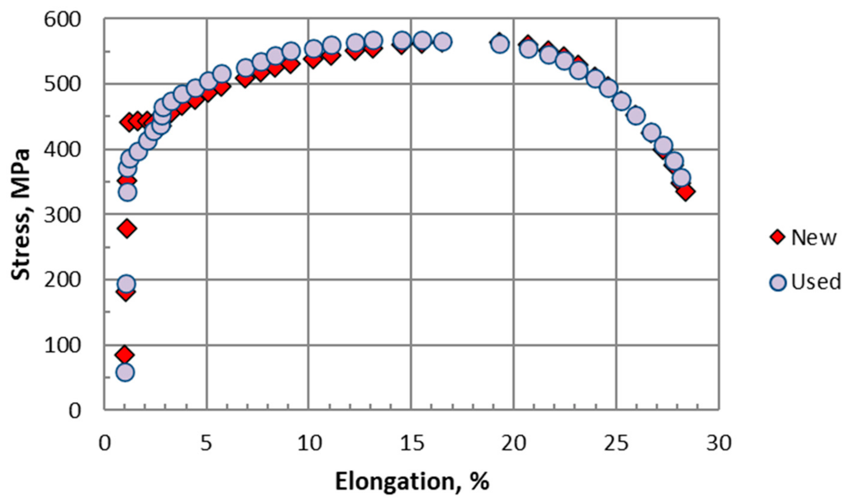
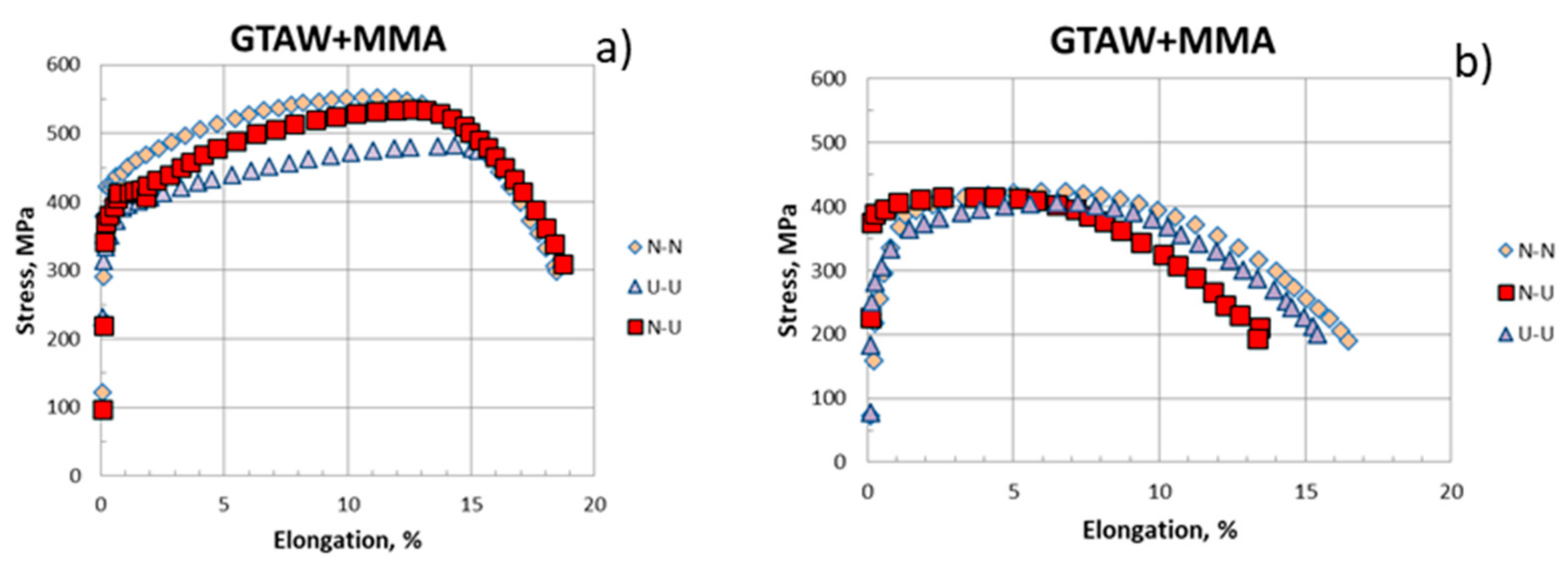
3.1. Strength
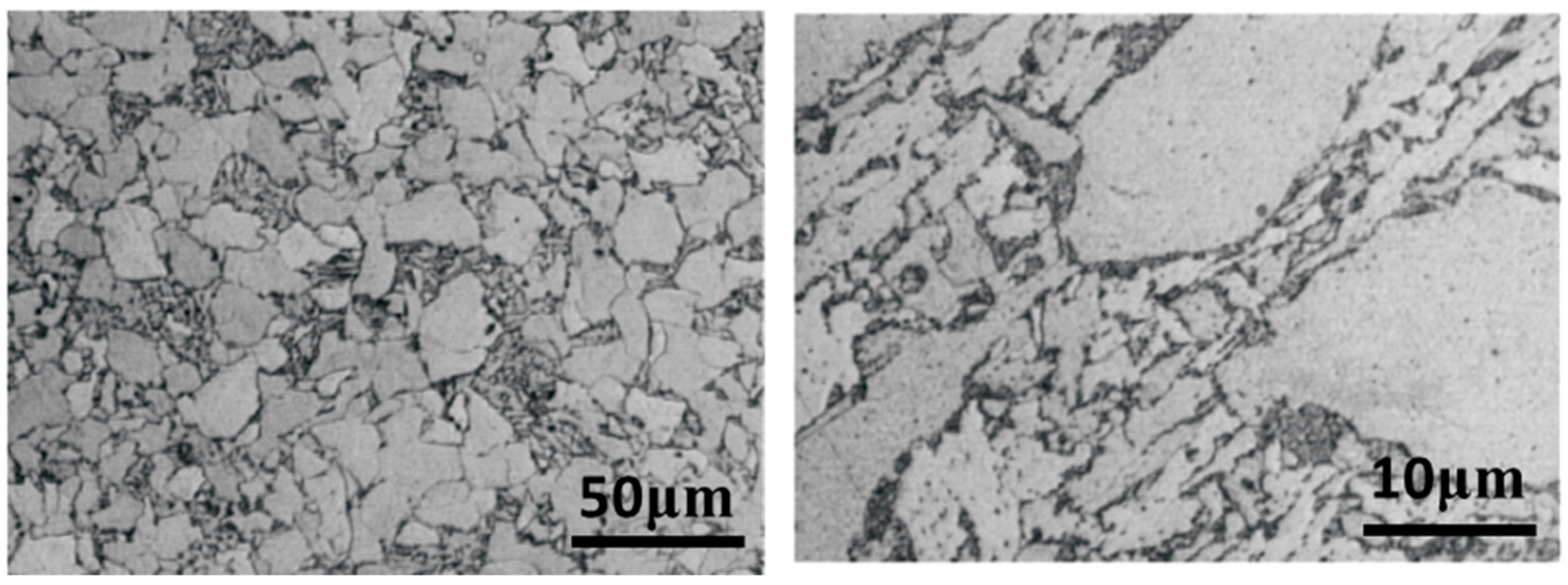
3.2. Microstructure
4. Conclusions
Author Contributions
Funding
Data Availability Statement
Acknowledgments
Conflicts of Interest
Abbreviations
| GTAW | Gas tungsten arc welding |
| MMA | Manual metal arc |
| YS | Yield strength |
| UTS | Ultimate tensile strength |
| CE | Carbon equivalent |
| PWHT | Post-welding heat treatment |
| BM | Base metal |
References
- VGB-S-517-00-2014-11-DE-EN Guidelines for Rating the Microstructural Composition and Creep Rupture Damage of Creep-Resistant Steel for High Pressure Pipelines and Boiler Components and Their Weld Connections. Available online: https://shop.vgbe.energy/s-517ebook.html (accessed on 16 April 2025).
- Tanski, T.; Sroka, M.; Zielinski, A. (Eds.) Creep; IntechOpen: London, UK, 2018. [Google Scholar] [CrossRef]
- Abe, F.; Kern, T.U.; Viswanathan, R. Creep-Resistant Steels; Elsevier: Amsterdam, The Netherlands, 2008. [Google Scholar]
- Kassner, M.E.; Perez-Prado, M.-T. Fundamentals of Creep in Metals and Alloys, 3rd ed.; Elsevier: Oxford, UK, 2015; ISBN 9780080994277. [Google Scholar]
- Nutting, R.J. The Structural Stability of Low Alloy Steels for Power Generation. In Proceedings of the Advanced Heat Resistant Steel for Power Generation, San Sebastian, Spain, 27–29 April 1998; pp. 12–30. [Google Scholar]
- Dobrzański, J. The Procedure for Determining the Time of Safe Service beyond the Design Service Time Based on Creep Testing. In Creep Characteristics of Engineering Materials; IntechOpen: London, UK, 2018. [Google Scholar] [CrossRef]
- Smallman, R.; Bishop, R. Modern Physical Metallurgy and Materials Engineerin-Science, Process, Applications, 6th ed.; Butterworth Heinemann: Portsmouth, NH, USA, 1999. [Google Scholar] [CrossRef]
- Dieter, G. Mechanical Metallurgy; McGraw-Hill: London, UK, 1988. [Google Scholar]
- Bendick, W.V.; Weber, H. Beurteilung von Bauteilen nach langer Zeitstandbeanspruchung. T. 1. VGB Kraftwerktechnik 1986, 66, 63–72. Available online: https://pascal-francis.inist.fr/vibad/index.php?action=getRecordDetail&idt=8101814 (accessed on 16 April 2025).
- Gibeling, J.C. Mechanical Testing and Evaluation. In Creep Deformation of Metals, Polymers, Ceramics, and Composites; ASM International: Almere, The Netherlands, 2000. [Google Scholar] [CrossRef]
- Zrilić, M. The Application of Local Approach to Residual Life Assessment of High Temperature Equipment Components. Ph.D. Thesis, Faculty of Technology and Metallurgy, University of Belgrade, Belgrade, Serbia, 2004. (In Serbian). [Google Scholar]
- Vodopivec, F. O Poškodbah Jekla v Parovodih in Metodah Za Njihovo Opredelitev. Železarski Zbornik 1990, 24, 145–152. [Google Scholar]
- Sadibašić, D.; Radović, N.; Grabulov, V. Influence of initial state on properties of mma welded 14mov 6 3 steel. Weld. Welded Struct. 2012, 57, 53–60. [Google Scholar]
- Łomozik, M.; Brózda, J. Optimization of Welding Methods for the Repair and Refurbishment of Heat Resisting Steel Components After Long Term Service and Their Life Prediction in the Polish Power Plants; Annual Report for COST 538 for 2007; The Institute of Welding: Gliwice, Poland, 2006. [Google Scholar]
- SRPS EN 10216-2:2020; Seamless Steel Tubes for Pressure Purposes—Technical Delivery Conditions—Part 2: Non-Alloy and Alloy Steel Tubes with Specified Elevated Temperature Properties. Institute for Standardization of Serbia: Belgrade, Serbia, 2020.
- Zieliński, A.; Zieliński, A.; Dobrzański, J.; Dziuba-Kałuża, M. Structure of welded joints of 14MoV6-3 and 13CrMo4-5 steel elements after design work time under creep conditions. Arch. Mater. Sci. Eng. 2013, 61, 69–76. [Google Scholar]
- Domovcová, L.; Beraxa, P.; Mojžiš, M.; Weiss, M.; Fujda, M.; Parilák, Ľ. Microstructure and Mechanical Properties of Steel Grade 14MoV6-3. Mater. Sci. Forum. 2014, 782, 137–140. [Google Scholar] [CrossRef]
- Hodžić, D.; Hajro, I. Impact Toughness of Steamline Material 14MoV6-3 After Long Term Exploitation. In Proceedings of the 14th International Research/Expert Conference “Trends in the Development of Machinery and Associated Technology”, Barcelona, Spain, 11–18 September 2010; TMT: Oslo, Norway, 2010; pp. 129–132. [Google Scholar]
- ISO 15614-1 2017; Specification and Qualification of Welding Procedures for Metallic Materials-Welding Procedure Test-Part 1: Arc and Gas Welding of Steels and Arc Welding of Nickel and Nickel Alloys. ISO: Geneva, Switzerland, 2017.
- Arandjelovic, M.; Djordjevic, B.; Sedmak, S.; Radu, D.; Petrovic, A.; Dikic, S.; Sedmak, A. Failure Analysis of Welded Joint with Multiple Defects by Extended Finite Element Method and Engineering Critical Analysis. Eng. Fail. Anal. 2024, 160, 108176. [Google Scholar] [CrossRef]
- Aranđelović, M.; Petrović, A.; Đorđević, B.; Sedmak, S.; Sedmak, A.; Dikić, S.; Radu, D. Effects of Multiple Defects on Welded Joint Behaviour under the Uniaxial Tensile Loading: Fem and Experimental Approach. Sustainability 2023, 15, 761. [Google Scholar] [CrossRef]
- Jakubowska, M.; Chulist, R.; Maj, L.; Sypien, A. Analysis of the Creep Mechanism of Low-Alloy Steel in Terms of Plastic Deformation. J. Mater. Eng. Perform. 2024, 33, 14433–14447. [Google Scholar] [CrossRef]
- Ro, U.; Kim, J.H.; Lee, H.; Kang, S.J.; Kim, M.K. Creep-Fatigue Damage Evaluation of Grade 91 Steel Using Interrupt Creep Fatigue Test. In Proceedings of the ASME 2018 Pressure Vessels and Piping Conference, Prague, Czech Republic, 15–20 July 2018. [Google Scholar] [CrossRef]
- Holdsworth, S. Creep-Fatigue Failure Diagnosis. Materials 2015, 8, 7757–7769. [Google Scholar] [CrossRef] [PubMed]
- Dobrzaski, J. Materials Science Interpretation of the Life of Steels for Power Plants. Open Access Libr. 2011, 3, 1–228. [Google Scholar]
- Zieliński, A.; Golański, G.; Sroka, M. Comparing the Methods in Determining Residual Life on the Basis of Creep Tests of Low-Alloy Cr-Mo-V Cast Steels Operated beyond the Design Service Life. Int. J. Press. Vessel. Pip. 2017, 152, 1–6. [Google Scholar] [CrossRef]
- Braun, M.; Sawada, K.; Kimura, K. Microstructural Changes around Grain Boundary after Long-Term Creep in Low-Alloy Steels. Int. J. Press. Vessel. Pip. 2020, 186, 104162. [Google Scholar] [CrossRef]
- Krauss, G. Martensite in Steel: Strength and Structure. Mater. Sci. Eng. A 1999, 273–275, 40–57. [Google Scholar] [CrossRef]
- Swindeman, R.W.; Santella, M.L.; Maziasz, P.J.; Roberts, B.W.; Coleman, K. Issues in Replacing Cr-Mo Steels and Stainless Steels with 9Cr-1Mo-V Steel. Int. J. Press. Vessel. Pip. 2004, 81, 507–512. [Google Scholar] [CrossRef]
- Boehler-Catalogue of Filler Materials. Available online: https://welding-expert.com/uploads/media/Weldingguide_ENGnew.pdf (accessed on 16 April 2025).
- Easterling, K. Physical Metallurgy of Welding; Butterworth-Heinemann Oxford: Oxford, UK, 1992. [Google Scholar]
- SRPS EN ISO 21952; Welding Consumables—Wire Electrodes, Wires, Rods and Deposits for Gas Shielded Arc Welding of Creep-Resisting Steels—Classification. Institute for Standardization of Serbia: Belgrade, Serbia, 2012.
- SRPS EN ISO 4136; Destructive Tests on Welds in Metallic Materials—Transverse Tensile Test. Institute for Standardization of Serbia: Beograd, Serbia, 2022.
- ASTM E 340-15; Standard Practice for Macroetching Metals and Alloys. ASTM: West Conshohocken, PA, USA, 2023. [CrossRef]
- ASTM E 407; Standard Practice for Microetching Metals and Alloys. ASTM: West Conshohocken, PA, USA, 2023. [CrossRef]
- Sadibašić, D. Optimizacija Tehnologije Zavarivanja Čelika Namenjenih Termoenergetskim Postrojenjima. Master’s Thesis, Faculty of Technology and Metallurgy, University of Belgrade, Belgrade, Serbia, 2010. [Google Scholar]
- Porter, D.A.; Easterling, K.E. Phase Transformations in Metals and Alloys, 3rd ed.; Butterworth-Heinemann Oxford: Oxford, UK, 1999. [Google Scholar]
- Bhadeshia, H.K.D.H.; Honeycombe, R.W.K. Steels Microstructure and Properties; Elsevier Ltd.: Amsterdam, The Netherlands, 2006; 344p. [Google Scholar] [CrossRef]
- SRPS EN 10028-2; Flat Products Made of Steels for Pressure Purposes—Part 2: Non-Alloy and Alloy Steels with Specified Elevated Temperature Properties. Institute for Standardization of Serbia: Belgrade, Serbia, 2017.
- Fujda, M. Metalographic Analysis of Tubes 10CrMo9-10 and 14MoV6-3 Steel Tubes; Report No. 2/2012; HF TUKE, KNoM: Košice, Slovakia, 2012. (In Slovak) [Google Scholar]
- SRPS EN ISO 15612; Specification and Qualification of Welding Procedures for Metallic Materials—Qualification by Adoption of a Standard Welding Procedure Specification. Institute for Standardization of Serbia: Belgrade, Serbia, 2018.


| C | Si | Mn | P | S | Cr | Mo | V | |
|---|---|---|---|---|---|---|---|---|
| EN 10216-2 [15] | 0.1–0.18 | 0.15–0.35 | 0.30–0.60 | 0.040 max. | 0.040 max. | 0.30–0.60 | 0.50–0.65 | 0.22–0.32 |
| Used (U) pipe | 0.14 | 0.30 | 0.56 | 0.019 | 0.015 | 0.39 | 0.58 | 0.23 |
| New (N) pipe | 0.15 | 0.22 | 0.48 | 0.012 | 0.010 | 0.47 | 0.57 | 0.24 |
| GTAW-wire [30] | 0.08 | 0.60 | 0.90 | - | - | 0.45 | 0.85 | 0.35 |
| MMA-electrode [30] | 0.065 | 0.35 | 1.20 | - | - | 0.40 | 1.00 | 0.50 |
| Sample | Pass Number | Tungsten Electrode, mm | Filler Material, mm | Current, A | Voltage, V | Protective Gas Ar, L/min |
|---|---|---|---|---|---|---|
| GTAW | 1 | Ø2.4 | Ø2.4 | 100 | 11.5 | 6–8 |
| 2 | Ø2.4 | Ø2.4 | 105 | 12.1 | 6–8 | |
| 3 | Ø2.4 | Ø2.4 | 100 | 12.9 | 6–8 |
| Sample | Pass Number | Tungsten Electrode, mm | Filler Material, mm | Current, A | Voltage, V | Protective Gas Ar, L/min |
|---|---|---|---|---|---|---|
| GTAW + MMA | 1 | Ø2.4 | Ø2.4 | 100 | 11.1 | 6–8 |
| 2 | - | Ø3.25 | 108 | 23.5 | - |
| UTS, MPa | YS, MPa | Elongation, A, % | |
|---|---|---|---|
| W MoVSi | 670 | 520 | 24 |
| E Mo V B 4 2 H5 | 660 | 510 | 22 |
| UTS, MPa | YS, MPa | Elongation, A, % | Reduction of Area, % * | |
|---|---|---|---|---|
| EN 10216-2 [15] | 490–690 | 365 | 20 | 40 |
| Used pipe (U sample) | 567 | 377 | 24.1 | 76 |
| New pipe (N sample) | 564 | 444 | 26.1 | 78 |
| Sample | Testing Temperature, °C | YS, MPa | UTS, MPa | Elongation, % | Place of Fracture |
|---|---|---|---|---|---|
| GTAW New-to-new | +20 | 396 | 519 | 17.5 | Base metal |
| +450 | 310 | 423 | 17.4 | Base metal | |
| GTAW New-to-used | +20 | 376 | 493 | 9.5 | BM—(Used pipe side) |
| +450 | 322 | 390 | 3.5 | BM—(Used pipe side) | |
| GTAW Used-to-used | +20 | 373 | 531 | 15.6 | Base metal |
| +450 | 302 | 415 | 15.5 | Base metal | |
| GTAW + MMA New-to-new | +20 | 426 | 552 | 17.7 | Base metal |
| +450 | 296 | 423 | 15.3 | Base metal | |
| GTAW + MMA New-to-used | +20 | 412 | 533 | 15.8 | BM—(Used pipe side) |
| +450 | 391 | 415 | 13.3 | BM—(Used pipe side) | |
| GTAW + MMA Used-to-used | +20 | 347 | 495 | 14.2 | Base metal |
| +450 | 312 | 407 | 13.5 | Base metal |
Disclaimer/Publisher’s Note: The statements, opinions and data contained in all publications are solely those of the individual author(s) and contributor(s) and not of MDPI and/or the editor(s). MDPI and/or the editor(s) disclaim responsibility for any injury to people or property resulting from any ideas, methods, instructions or products referred to in the content. |
© 2025 by the authors. Licensee MDPI, Basel, Switzerland. This article is an open access article distributed under the terms and conditions of the Creative Commons Attribution (CC BY) license (https://creativecommons.org/licenses/by/4.0/).
Share and Cite
Ahmed, E.A.S.; Radović, N.; Glišić, D.; Dikić, S.; Milovanović, N.; Opačić, M.; Lozanović, J. Fracturing in 14MoV6-3 Steel Weld Joints—Including Base Metals—After a Short Time in Service. Metals 2025, 15, 483. https://doi.org/10.3390/met15050483
Ahmed EAS, Radović N, Glišić D, Dikić S, Milovanović N, Opačić M, Lozanović J. Fracturing in 14MoV6-3 Steel Weld Joints—Including Base Metals—After a Short Time in Service. Metals. 2025; 15(5):483. https://doi.org/10.3390/met15050483
Chicago/Turabian StyleAhmed, Esmail Ali Salem, Nenad Radović, Dragomir Glišić, Stefan Dikić, Nikola Milovanović, Mirjana Opačić, and Jasmina Lozanović. 2025. "Fracturing in 14MoV6-3 Steel Weld Joints—Including Base Metals—After a Short Time in Service" Metals 15, no. 5: 483. https://doi.org/10.3390/met15050483
APA StyleAhmed, E. A. S., Radović, N., Glišić, D., Dikić, S., Milovanović, N., Opačić, M., & Lozanović, J. (2025). Fracturing in 14MoV6-3 Steel Weld Joints—Including Base Metals—After a Short Time in Service. Metals, 15(5), 483. https://doi.org/10.3390/met15050483