Abstract
Valve microstructure is important during hot forging. Austenitic 21-4N steel is often used in exhaust valves. In this study, the microstructure evolution of the forging valve process was predicted using the internal state variables (i.e., average grain size, recrystallized fraction, and dislocation density) modus for 21-4N. First, 21-4N was subjected to hot compression tests on a Gleeble-1500D and static grain growth tests in a heating furnace. A set of uniform viscoplastic constitutive equations was established based on experimental data. Next, the determined unified constitutive equations were conducted in DEFORM-3D, and the microstructure evolution of 21-4N during forging was calculated. Finally, the simulation results of grain size evolution were validated via experiments. Results showed good consistency between the simulations and experiments. Thus, the models adequately predicted the microstructure evolution.
1. Introduction
The valve is an important part of the engine. Engine valve failure may cause the entire engine to fail [1,2,3,4,5]. Thus, the quality of the valve head is important. The valve microstructure is a main factor in future engine applications [6,7,8]. Austenitic 21-4N stainless steel is widely used for valves because of its good balance between strength and toughness and good wear resistance in an extreme working environment [9]. However, austenitic 21-4N stainless steel has poor plasticity and a narrow range of processing temperature. Particularly, cracks easily form on austenitic 21-4N stainless steel during forging. Therefore, proper process parameters for austenitic 21-4N stainless steel is important to control the microstructure evolution.
Over the past decades, considerable effort has been made on modeling microstructural evolution and the flow behavior of materials in high-temperature deformations. Jiang et al. [10] studied a recrystallization model and the microstructure evolution in the thermal deformation process of 690 alloys. The correctness of the finite element (FE) analysis method was verified by comparing the simulation results with the actual manufacturing materials. Wang et al. [11] established a constitutive equation, which is essential for predicting the response of materials to thermal deformation. Sun et al. [12] studied the isothermal hot compression tests of IN028 alloy at temperatures ranging from 950 to 1050 °C and strain rate ranging from 0.01 to 30 s−1. Hyperbolic sine-type constitutive equations were used to simulate the mechanical behaviors of IN028 alloy. Li et al. [13] studied the material characteristics and process parameters of the open-die warm extrusion process for the spline shaft of 42CrMo steel. Xiao et al. [14] measured the microstructures, grain sizes, and microhardness of Ti-6Al-4V under different deformation conditions. Lin et al. [15] studied the thermal tensile deformation behavior and fracture characteristics of a typical Ni-based superalloy. Chai et al. [16] studied the hot flow behavior of 20CrMnTiH steel using isothermal compression tests at temperatures ranging from 700 to 850 °C and strain rates ranging from 0.01 to 10 s−1. Xiao et al. [17] studied the constitutive modeling for the high-temperature performance of 1Cr12Ni3Mo2VNbN martensitic steel. Lin et al. [18] studied the microstructure evolution in the thermal deformation process of high-temperature Ni-based alloy. The thermal compression test of Ni-base superalloy was conducted under the strain rate range of 0.001–1 s−1 and deformation temperature range of 920–1040 °C. Optical microscopy and transmission electron microscopy (TEM) were performed to investigate the evolution of dynamic recrystallized grain and dislocation density. Lin et al. [19,20] studied the compressive deformation behavior of 42CrMo steel at temperatures ranging from 850 to 1150 °C and strain rates ranging from 0.01 to 50 s−1 on a Gleeble-1500 thermo-simulation machine. A modified model of the relationship among the flow stress, strain rate, and temperature of the 42CrMo steel was proposed based on the strain compensation and rate. Tang et al. [21] studied the metadynamic recrystallization behavior of a Ni-based superalloy through uniaxial solidity tests with temperatures between 950 and 1100 °C and strain rates between 0.01 and 1 s−1. Tang et al. [22] investigated the microstructure evolution of IN718 during radial-axial ring rolling using a unified internal state variable material model.
Although many studies on the simulation of microstructure evolution are available, studies on the microstructure evolution of forging valve process are limited. Zhu et al. [1] studied the microstructure mapping of Nimonic 80A valve head in closed-die forging. The hardness, grain size, dislocation, and secondary phase of the valve head were investigated through light microscope, X-ray diffraction, TEM, and FE methods. Jeong et al. [7] predicted the microstructure evolution of Nimonic 80A valve head in closed-die forging. Flow curve, recrystallized grain size, recrystallized volume fraction, and grain growth were investigated, and the Zener-Hollomon equation was established. Quan et al. [23] studied the constitutive model of extruded heat-resistant 3Cr20Ni10W2 alloy with dynamic recrystallization kinetics. However, microstructural research on the heat resistance of 21-4N steel valve head during forging has yet to be reported.
2. Experimental Program and Analysis
In this study, the microstructure evolution in the forging process of valves was predicted using an internal state variable method for 21-4N. First, 21-4N was subjected to hot compression tests on a Gleeble-1500D and static grain growth tests in a heating furnace. A set of consolidated viscoplastic constitutive equations was developed from the experimental data. Next, the determined unified constitutive equations were realized in DEFORM-3D (11.0, Scientific Forming Technologies Corporation, Columbus, OH, America), and the microstructural evolution of 21-4N in the forging process was predicted. Finally, the simulation results on grain size evolution were verified via experiments.
2.1. Compression Tests
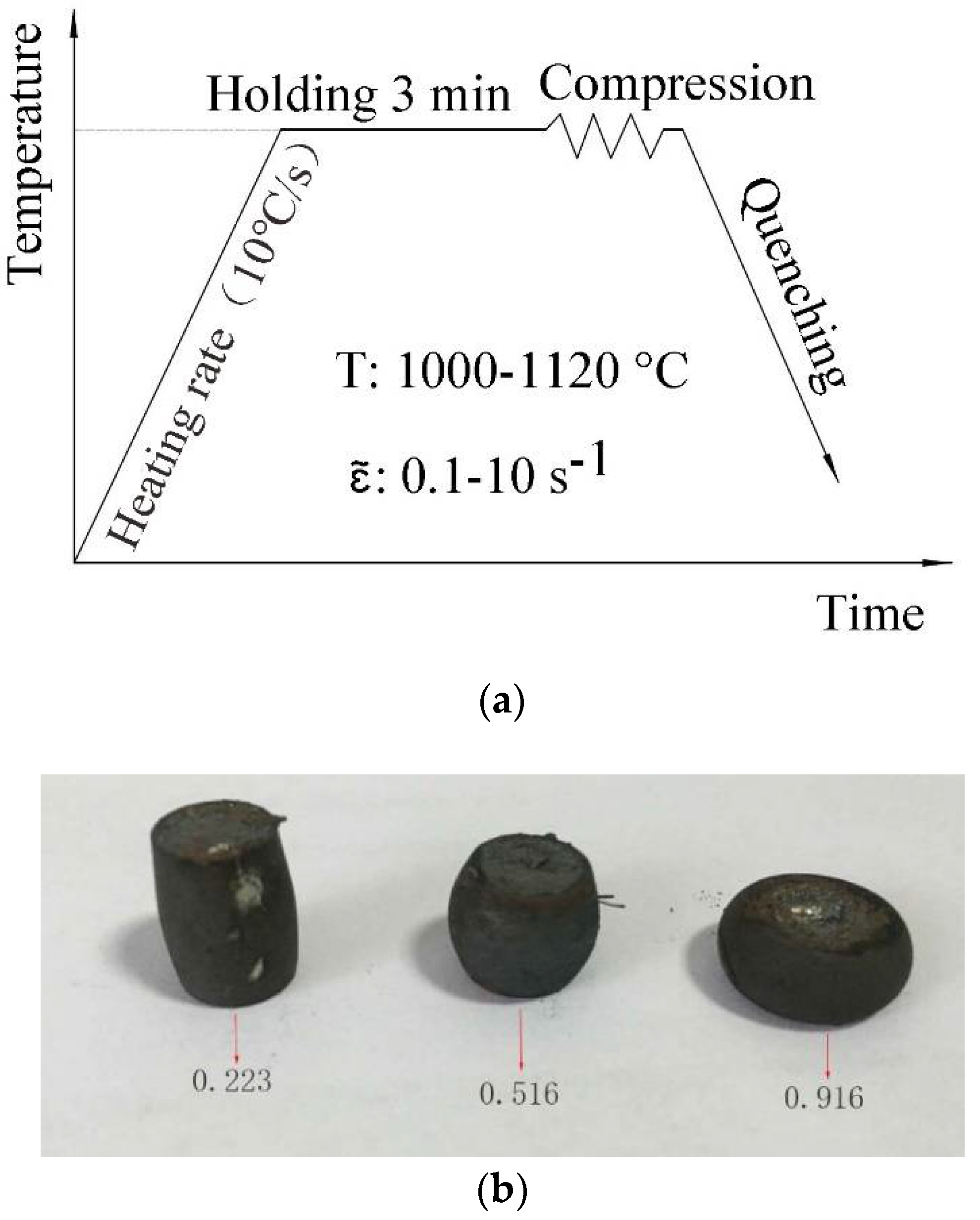
Microstructure response, recrystallization, and grain growth are evident during hot forging. Thus, hot compression tests were conducted to investigate the microstructure evolution and rheological stress curves. Specimens with 8 mm width and 15 mm length were machined. The compression tests were performed on a Gleeble-1500D thermo-simulation machine at Tsinghua University. Compression tests were performed at temperatures ranging from 1000 to 1120 °C; strain rate range of 0.1–10 s−1; and true strains of 0.223, 0.511, and 0.916.
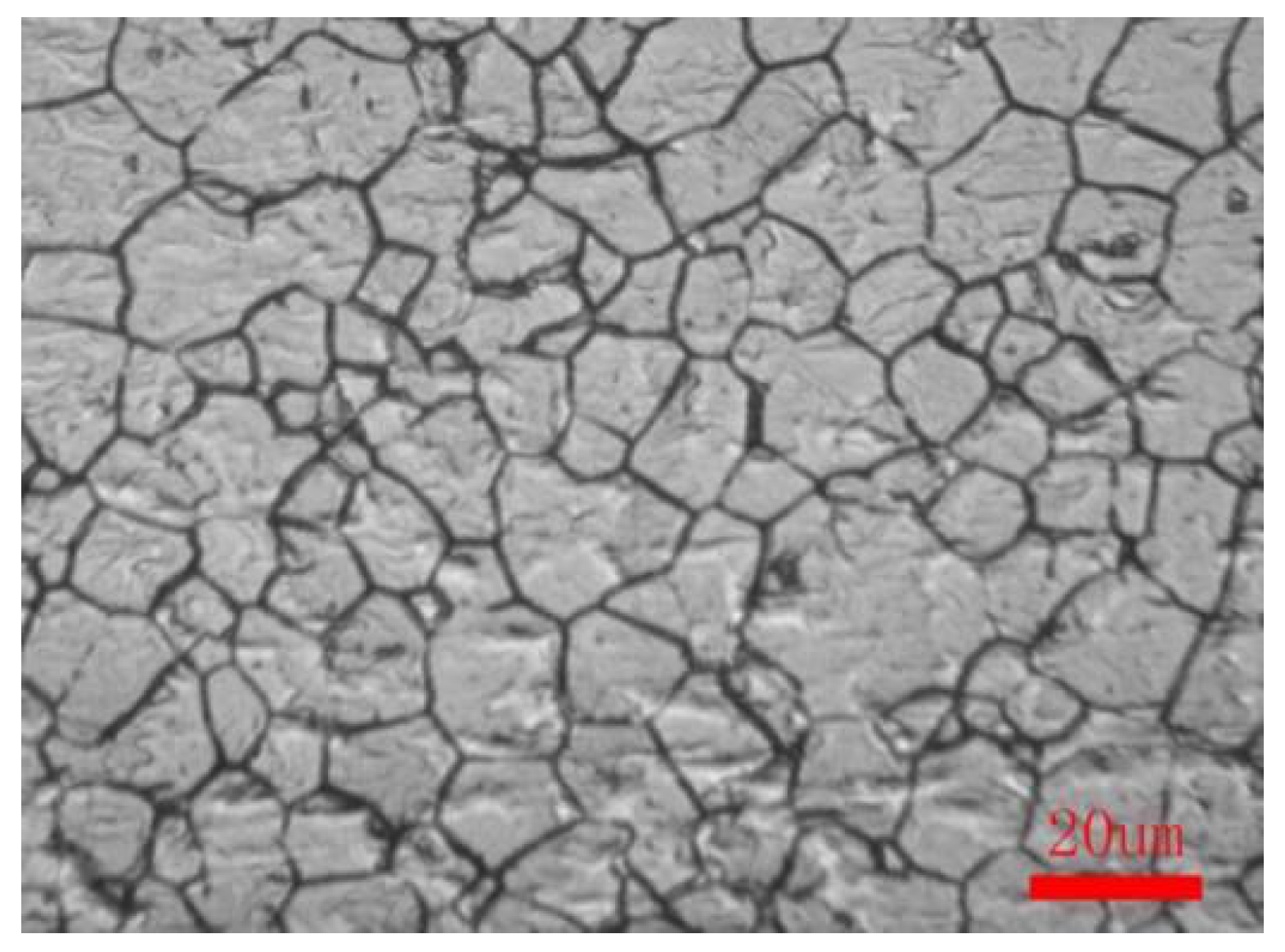
The microstructure was observed with an 11XD-PC inverted optical microscope. Figure 1 shows the initial microstructure of 21-4N. The chemical composition of 21-4N is listed in Table 1. The matrix for 5Cr21Mn9Ni4N was austenitic and granular carbide. The average grain size was approximately 16 μm. Figure 2a shows the temperature profiles for the compression tests of 21-4N. Figure 2b shows the specimens after the compression tests. Fracture was not observed on the specimens during the tests. A thermocouple was attached to the specimens to measure the temperature. After compression, the specimens were quickly quenched with cooling water to keep the microstructure. The flow curves of 21-4N are shown in Figure 3.
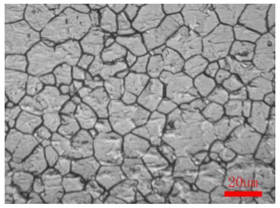
Figure 1.
The 21-4N raw material microstructure. Reproduced with permission from [24]. Copyright Elsevier, 2017.

Table 1.
Chemical composition of the 21-4N sheet (wt. %).
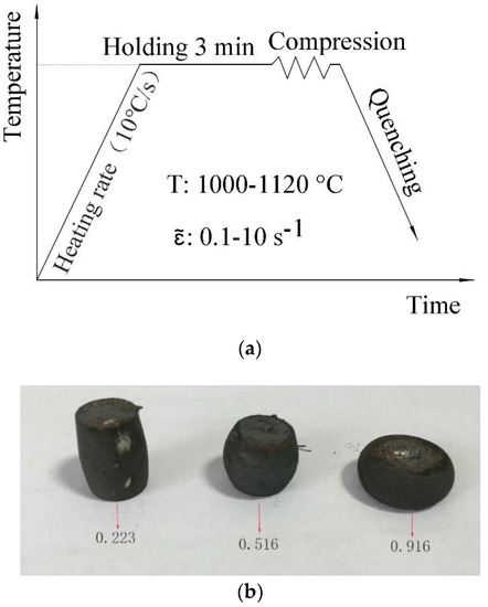
Figure 2.
Compression tests of 21-4N. (a) Temperature profiles for the compression tests of 21-4N. (b) Specimens after the compression tests.
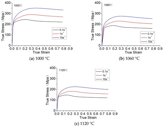
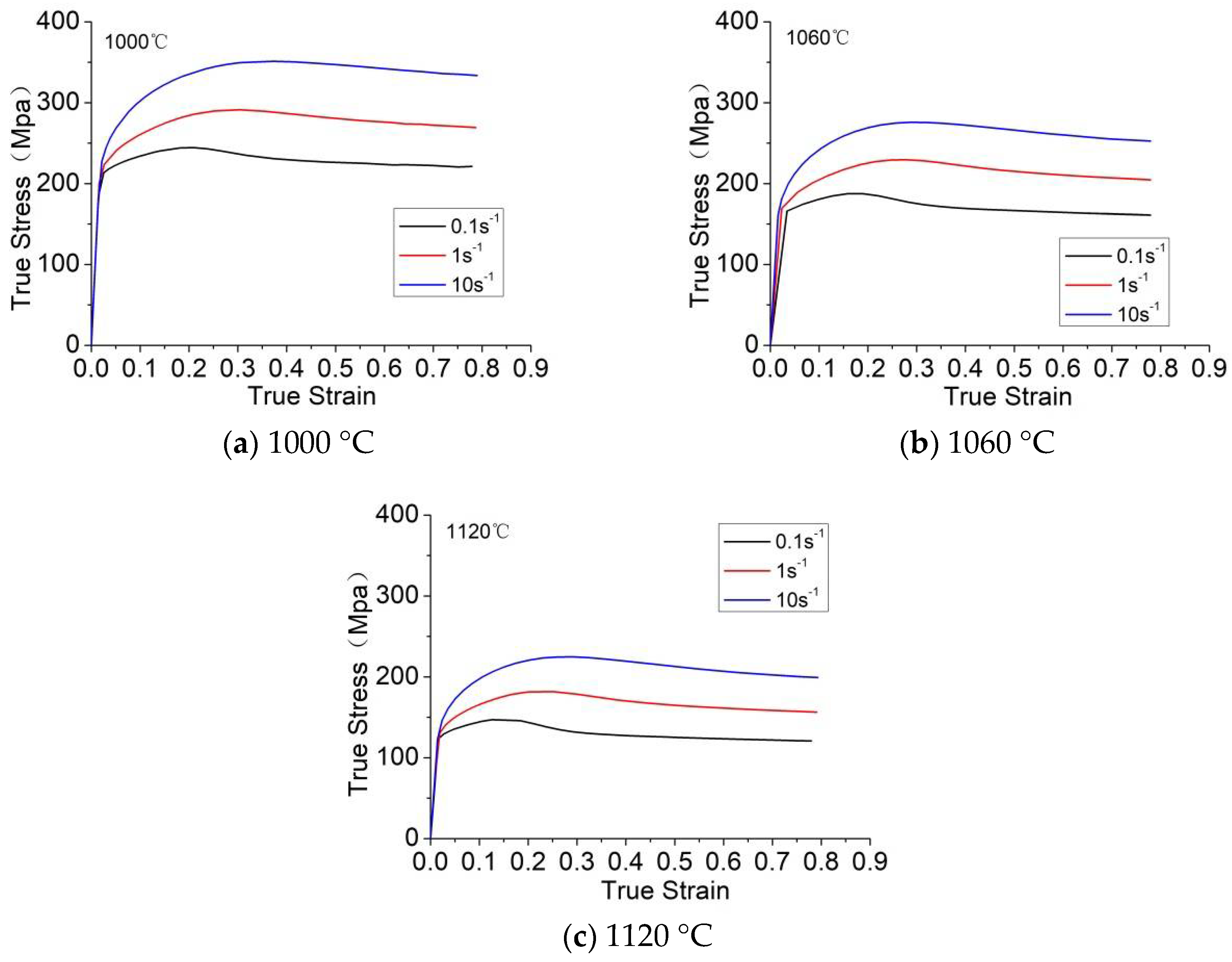
Figure 3.
Compressive true stress-true strain curves of the 21-4N with various strain rates.
The results of the stress-strain curves generally show that the rheological stress decreases with the increase in temperature or decrease in strain rate, whereas the softening effect increases. At a given temperature, flow stress increases with the strain rate. For a given strain rate, flow stress decreases with the increase in temperature. The curves present a peak stress in the flow curve at a specific strain, followed by flow softening or steady state.
The average grain size was measured through Image-Pro Plus 6.0 (IPP, Media Cybernetics, Rockville, MD, America), and the intercept method was used to measure the grain size. Test results are shown in Table 2. From the table, the average grain size decreases with the increase of strain at the same strain rate and temperature. In addition, the average grain size increases with the temperature.
Table 2.
Average grain size (in μm) at different strain rates and temperatures.
2.2. Static-State Grain Growth Tests
The experiment for static-state grain growth was performed at the University of Science and Technology, Beijing. The specimens were heated to different holding temperatures T (T = 1000, 1060, and 1120 °C) and different holding times t (t = 10, 20, 30, and 40 min). The heating rate is 10 °C/s.
After insulation was completed, the specimens were quickly quenched with cooling water to preserve the microstructure.
Table 3 shows the grain size of the valves after static grain growth tests. From the table, the average grain size increases with the heat preservation time. The average grain size also increases with the temperature in the same heat preservation time. Figure 4 shows the microstructure of 21-4N at temperature of 1120 °C with different holding times. As shown in Figure 4, the increase in the average grain size is insignificant. At 1120 °C heat preservation, grain growth is not evident because of the pinning effect of carbide in austenite, which inhibits grain growth; moreover, the holding time is more than 40 min. At above 1120 °C heat preservation, the carbide dissolves and the grain size rapidly increases.
Table 3.
Average grain size at different holding times and temperatures (Unit: μm).
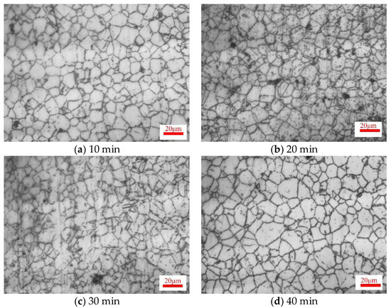
Figure 4.
Microstructures of 21-4N at 1120 °C with different holding times.
3. FE Modeling of the Hot Forging Process
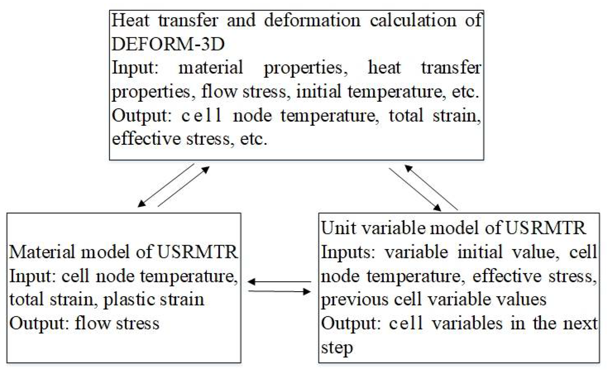
Valve microstructure is important during hot forging. Numerical calculation was performed through DEFORM-3D. The evolution model of 21-4N was incorporated into the DEFORM-3D user subroutines (i.e., MTR.f and UPD.f). The secondary development technology must compile two user-defined subroutines, namely, USRMTR and USRUPD, to place into the FE software. USRMTR is mainly used to compile the material flow stress equation; whereas USRUPD is mainly used to implement the coupling calculation update of various physical variables in the model, such as strain, dislocation density, and grain size. The relationship between these two user-defined subroutines and the FE software is shown in Figure 5.
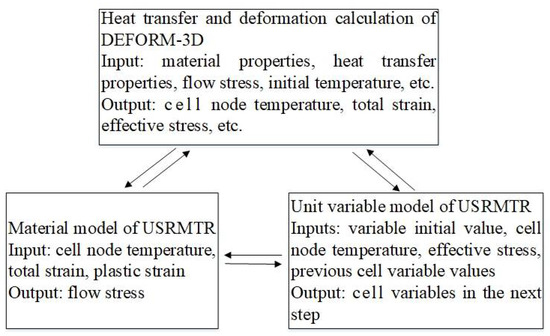
Figure 5.
Relationship of thermal-force microstructure of DEFORM-3D.
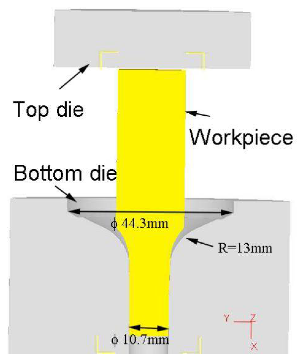
Then, the microstructure evolution of 21-4N during forging process would be simulated. The forging model was constructed using Pro/E software (PTC, Needham, MA, USA) and then imported into the DEFORM-3D software of STL format. The geometrical model comprises a workpiece, a top die, and a bottom die (Figure 6). The mesh elements of the workpiece are tetrahedral. The main process parameters for the simulation are listed in Table 4.

Figure 6.
FE model for forging simulation.
Table 4.
Parameters for hot forging simulation.
4. Hot Forging of Valves
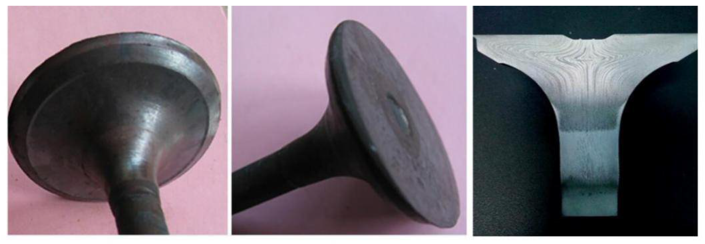
In the present study, a series of experiments on forging valves was conducted at the Guangdong Huaiji Auto-parts Mfg. Inc., Ltd. (Zhaoqing, China) to validate the hot forging FE model with the constitutive model [25]. The valve was manufactured through hot forging with a 160-ton hydraulic press (J53-160C, China). The forging temperature range of the 21-4N workpiece during valve forging is approximately 1060–1120 °C. Environment temperature is 20 °C. The speed of the top die is 20 mm/s. Figure 7 shows a picture of the forging machine. After forging, the head of the valve was cut along the axis, and a half valve was polished. The grain size was measured using an optical microscope. Figure 8 shows the forged valves in the experiment. From the figure, the flow line of the valve head and the rod is obviously even. The main flow line is perpendicular to the valve, which ensures that the valve does not easily break under pressure.
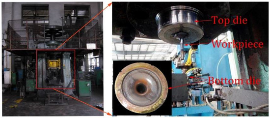
Figure 7.
Hot forging machine for valves.
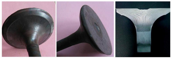
Figure 8.
Manufacturing valves using the forging machine.
5. Constitutive Equations and Microstructural Model of 21-4N
The unified viscoplastic constitutive equations were developed to predict flow stress and microstructure evolution for many types of metal materials [24,25,26,27,28,29,30,31,32,33,34,35,36,37,38,39,40]. Recovery, recrystallization, grain size, and dislocation density were well described in the framework of the unified viscoplastic constitutive model. Deformation temperature, strain rates, and equivalent true strain were also embodied in the unified constitutive equations. The unified viscoplastic constitutive equations for 21-4N during hot forming can be expressed as Equations (1)–(7):
where Equation (1) is the viscoplastic strain variation, is the hardening parameter, is the initial yield stress, is the average grain size, and is the original grain size. Equation (2) is the recrystallization fraction evolution that varies from 0 to 1 depending on the normalized dislocation density . Equation (3) is the recrystallized incubation fraction evolution. The recrystallized incubation fraction varies from 0 to 1 with the normalized dislocation density . Equation (4) is the evolution of the hardening parameter , which varies with the normalized dislocation density . Equation (5) is the evolution of normalized dislocation density in the deformation process. The first term is the dislocation density evolution due to multiplication and static recovery. The second term is the effect of dynamic recovery, and the third term the effect of recrystallization on the dislocation density evolution. Equation (6) describes the evolution of average grain size. and are material constants. The first term of the equation describes static grain growth. The second term models grain refinement of recrystallization. Equation (7) describes the variation of effective flow stress . E is the Young’s modulus, is the total equivalent strain, and is the inelastic strain. , , , , , , , , , , and are material constants. are material constants that are dependent on temperature. The corresponding temperature-dependent parameters in the equations are listed in Equation (8), where are material constants. represent thermal activation parameters in Equation (8). Rg = 8.31 J⋅mol−1⋅K−1 is the universal gas constant, and is the categorical temperature in K:
The calculated data were obtained through numerical integration using the Eulerian method. The calculation procedure of the constitutive equations was programmed into the genetic algorithm (GA) toolbox in MATLAB software [25,31,32,33]. When determining the material constants, the population size of 200, algebra of 5000, and hybridization rate of 0.8 were set. The experimental data of effective stress and average grain size were used in the optimization. The global objective function can be defined by the sum of individual sub-objective functions. The optimization procedure can be expressed as Equation (9) follows:
The first term of Equation (9) describes the flow stress. The second term of Equation (9) describes the average grain size. Lin [37,38] defined two sub-objective functions on the basis of the logarithmic error between calculated values and experimental values. The following are the two sub-objective functions Equations (10) and (11):
where is the residual for flow stress. is the residual for average grain size. () represents the material constants required to be determined, and correspond to A10, A2, K10…QE. L is the value of the testing temperatures. The number of strain rates at a chosen deformation temperature is M. N represents the number of data points at a given strain rate and a particular deformation temperature. and are the computational stresses and computational grain sizes, respectively, for the same strain level and strain rate under a certain temperature. Similarly, and are the experimental stresses and experimental average grain sizes, respectively, for the same strain level and strain rate j at a given temperature.
The process of determining the material constants in the constitutive equation are divided into two steps.
First, the activation energy of hot deformation and parameter are calculated in Equation (1) using an analytic method. Then, the activation energy of grain growth and the parameters of and in the equation are determined using the experimental data of static grain growth.
Second, the GA optimization technique is used to determine the residual constants and corresponding temperature-dependent variables in the constitutive equation. The values of the material constants are listed in Table 5.
Table 5.
Determination of material constants of constitutive equations.
The determined unified viscoplastic constitutive equations were validated by comparing the calculated data (solid curves) with the experimental data (symbols). The prediction of the stress model and the comparison of experimental values are shown in Figure 9. Figure 10 shows the computed and experimental grain size results at different strains, strain rates, and temperatures. The calculated results agreed well with the experimental results. This result indicates that the constitutive equations enable the effective prediction of the microstructure evolution and flow stress of 21-4N [41].
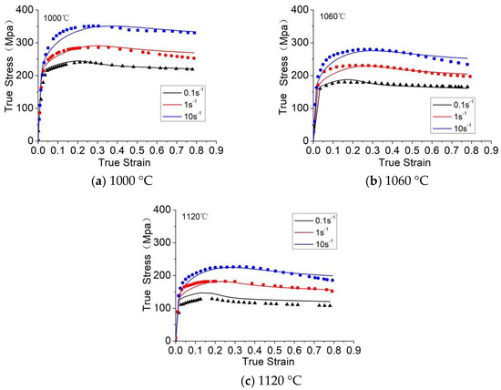
Figure 9.
Comparison of the stress model prediction (lines) and experimental (points) values. Reproduced with permission from [24]. Copyright Elsevier, 2017.
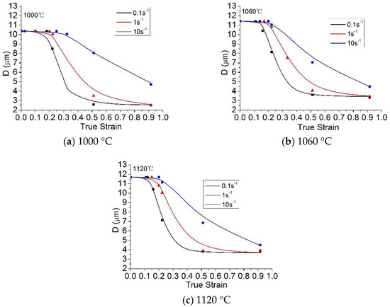
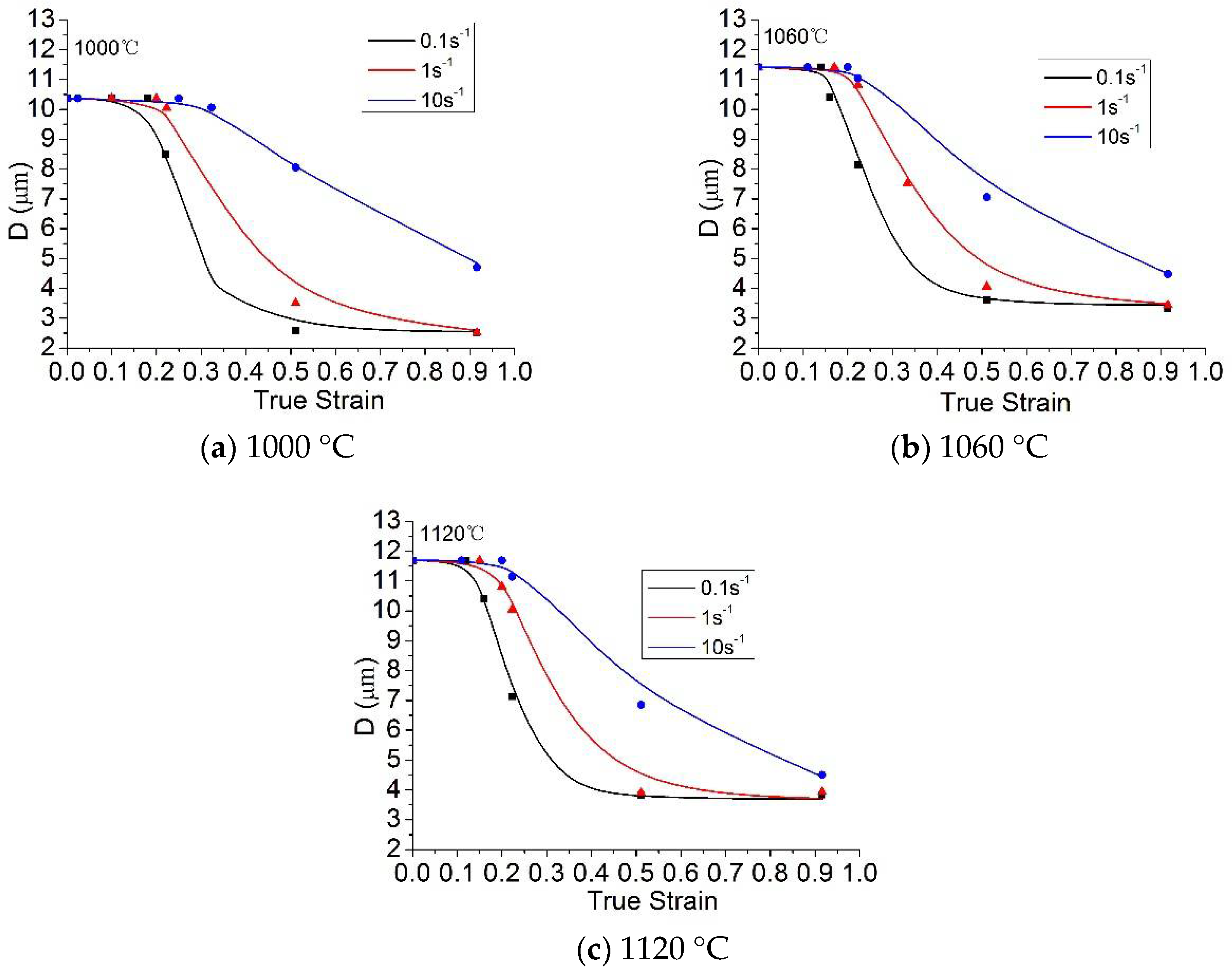
Figure 10.
Average grain size prediction (solid lines) and experimental (points) values. Reproduced with permission from [24]. Copyright Elsevier, 2017.
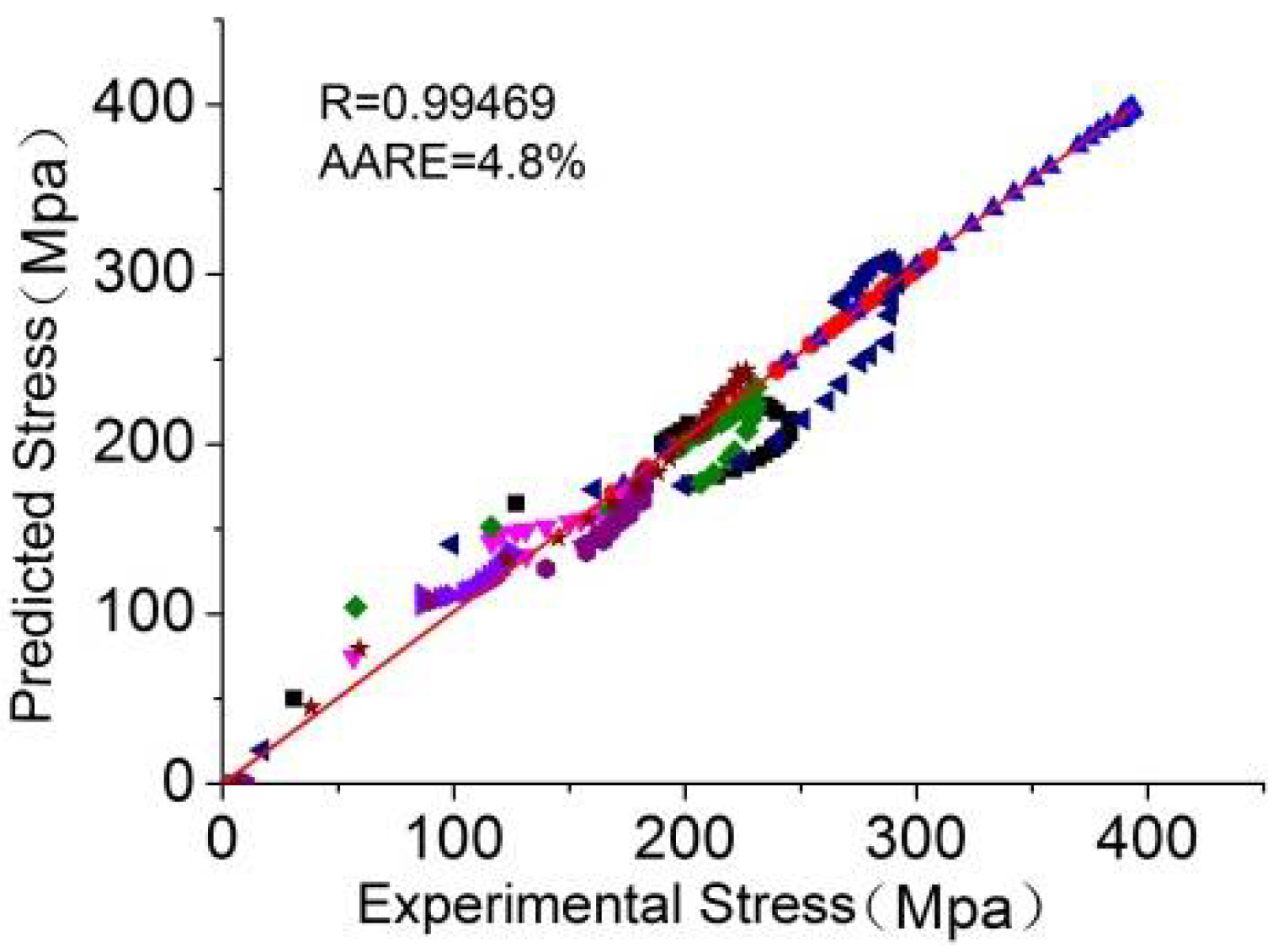
The uniform constitutive equation can be compared by using the correlation coefficient R and absolute mean relative error AARE. The correlation coefficient R and AARE were 0.99469 and 4.8% (Figure 11), respectively. These values imply the good prediction capability of the model.

Figure 11.
Flow stress relativity of the predicted and experimental values. Reproduced with permission from [24]. Copyright Elsevier, 2017.
6. Microstructure Evolution of 21-4N in the Forging Process
6.1. Predictions of State Variables
Figure 12a presents the stress field for the workpiece during the forging process. The transition area between the large strain area (yellow region) and the small strain region (blue region) is the place where the maximum stress occurs. This non-uniform stress field may cause the propagation of strain from the deformed regions to the undeformed regions; thus, it facilitates the entire forging process. Figure 12b shows the distribution of effective strain. The effective strain in the main deformation zone is about 1.7, and the maximum effective strain is 2.4. Figure 12c shows the distribution of dislocation density. The normalized dislocation density undergoes minimal change in the undeformed regions. The value of the largely deformed regions is 0.121. Thermal field is illustrated in Figure 12d. Here, the main factor determining the thermal field is the geometry of the workpiece. The temperature in the surface area is usually lower than that in the center of the artifact. Thermal field, strain field, and stress field interact with one another. The maximum temperature is approximately 1130 °C. In hot material processing, once dislocation density reaches a critical value, , recrystallization occurs after an incubation period. Figure 12e shows that the recrystallized volume fraction of the workpiece reaches 0.963 in the forging area. Grain size is refined from 12 μm to 5.15 μm in the rolled area owing to recrystallization (Figure 12f).
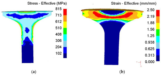
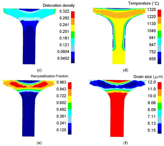
Figure 12.
Distributions of internal state variable.
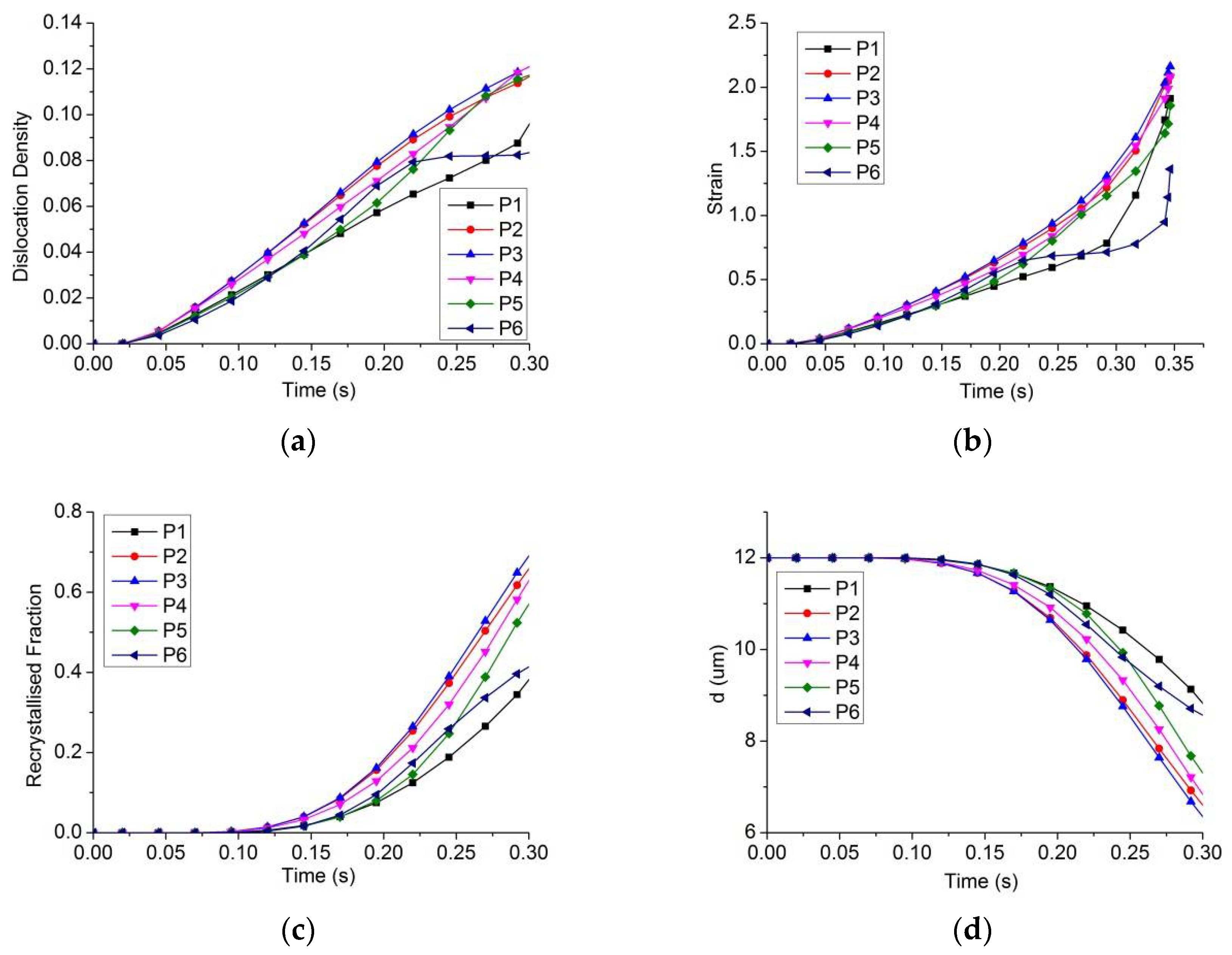
Six points were selected to depict the changes of dislocation density, strain, recrystallization fraction, and grain size during the deformation process at the top die speed pf 20 mm/s (Figure 13). Once the material reaches a critical density, the normalized dislocation density increases (Figure 14 a) immediately from the original state. The normalized dislocation density for the initial deformed section is highly similar to the effective stress (Figure 14a) because the increment in dislocation density is directly related to plastic strain rates, as described in Equation (1).
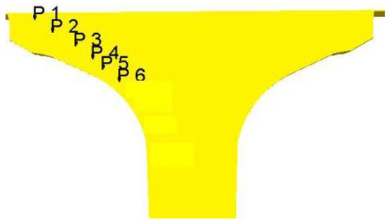
Figure 13.
Forging valve profile.
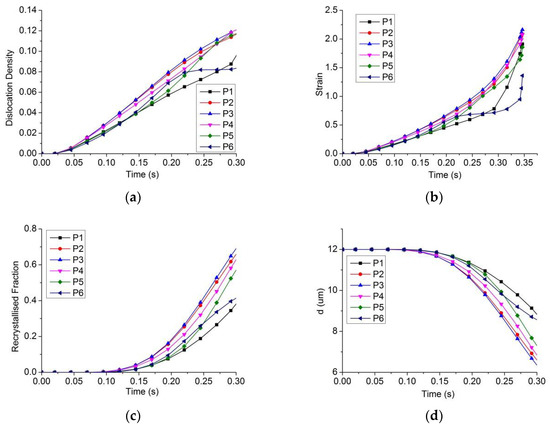
Figure 14.
Distribution of variables at different points 1–6. (a) Normalized dislocation density; (b) Equivalent strain; (c) Recrystallization fraction; (d) Grain size.
The microstructural evolution exhibits a different behavior. Dynamic recrystallization occurs because dislocation density reaches critical levels. As shown in Figure 14c, the material does not begin to recrystallize immediately. The significant delay is caused by the onset parameter control and the critical dislocation density accumulated from the deformation. Grain refinement only happens when dynamic recrystallization begins. The average grain size (Figure 14d) decreases to approximately 6.5 μm from 12 μm just after forging because of dynamic recrystallization and static recrystallization.
6.2. Effects of Processing Parameters on the Forging Process
Processing parameters are important parameters for determining the forging process and deformation behavior of materials. The effects of workpiece temperature, top die speed, die temperature, and friction (m) on the forging process were investigated by measuring the maximum force and average grain size of the valve head.
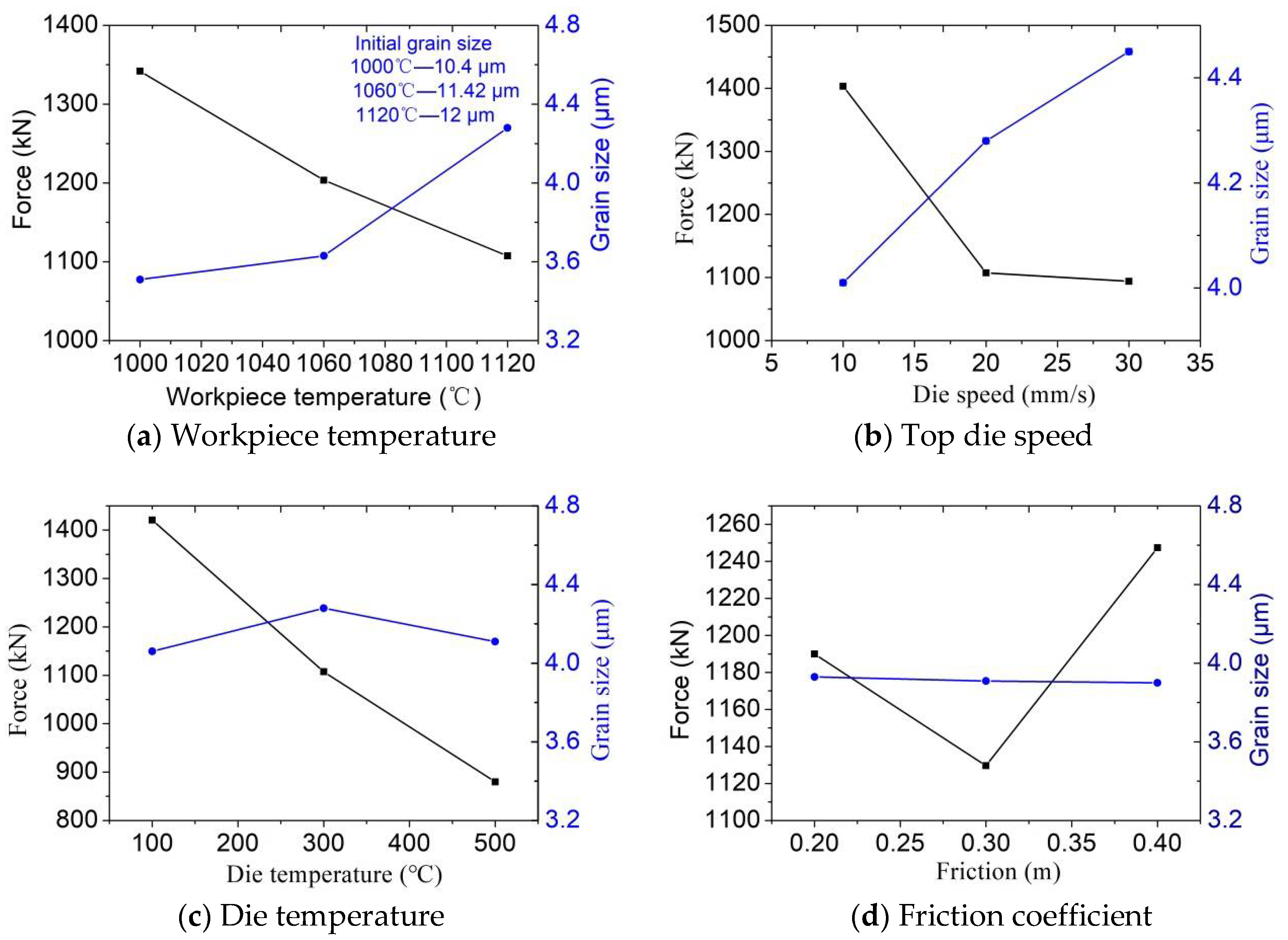
Figure 15a shows the variation trend of grain size and force with increasing workpiece temperature. When the workpiece temperature is 1000 °C, the initial grain size is 10.4 μm, the grain size after forging is 3.5 μm, and the force is 1350 kN. When the workpiece temperature is 1060 °C, the initial grain size is 10.4 μm, the grain size after forging is 3.6 μm, and the force is 1200 kN. When the workpiece temperature is 1120 °C, the initial grain size is 10.4 μm, the grain size after forging is 4.3 μm, and the force is 1100 kN. As a general trend, the grain size increases with the temperature of the workpiece, and the force decreases with the temperature of the workpiece. However, the lower the initial temperature of the billet is, the higher the forging force is. In addition, forging is likely to cause surface defects and cracks in the final valve at low temperatures.
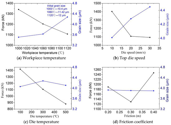
Figure 15.
Effects of processing parameters on the forging process.
Figure 15b shows the variation trend of grain size and force with the increase of the top die speed. When the top die speed is 10 mm/s, the grain size after forging is 4.0 μm, and the force is 1400 kN. When the top die speed is 20 mm/s, the grain size after forging is 4.225 μm, and the force is 1110 kN. When the top die speed is 30 mm/s, the grain size after forging is 4.45 μm, and the force is 1090 kN. As a general trend, the grain size increases as the top die speed increases, and the force decreases as the top die speed increases.
Figure 15c shows the effects of die temperature on the forging process. Apparently, because the heat transfer time between the blank and the die is considerably short, the influence of die temperature on the forging process is lower than that of the initial billet. When the die temperature is 100 °C, the grain size after forging is 4.05 μm, and the force is 1450 kN. When the die temperature is 300 °C, the grain size is 4.25 μm, and the force is 1100 kN. When the die temperature is 500 °C, the grain size after forging is 4.1 μm, and the force is 880 kN. As a general trend, the grain size increases first and then decreases as the die temperature rises, and the force decreases as the die temperature increases.
Figure 15d shows the variation trend of the grain size and force with increasing friction coefficient. When the friction coefficient is 0.2 m, the force is 1190 kN. When the friction coefficient is 0.3 m, the force is 1130 kN. When the friction coefficient is 0.4 m, the force is 1250 kN. As a general trend, in the process of increasing the friction coefficient, the grain size after forging basically remains unchanged at the level of 3.9 μm. The magnitude of the force first decreases and then increases as the friction coefficient increases.
6.3. Average Grain Size by Experiment
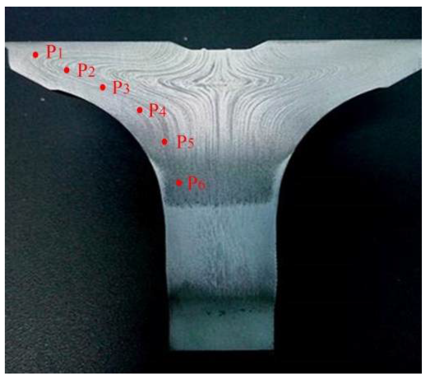
Six points were chosen to depict the average grain size (Figure 16). The initial temperature of the workpiece was 1100 °C, and the die temperature was 300 °C. Environment temperature was 20 °C. The speed of the top die was 20 mm/s. The grain sizes with the rod part are consistent in the part of the plate, that is, approximately 8 μm, because deformations are significantly uniform and large. Figure 12f is a predicted image of grain size after forging due to dynamic recrystallization and static recrystallization. Figure 17 is the actual average grain size of 21-4N in the forging process. As can be seen from the figure, the predicted value of P1 is 8.5 μm, and the actual value is 4 μm. The predicted value of P2 is 8 μm, and the actual value is 5 μm. The predicted value of P3 is 7 μm, and the actual value is 6 μm. The predicted value of P4 is 6.5 μm, and the actual value is 5.5 μm. The predicted value of P5 is 6.2 μm, and the actual value is 5.8 μm. The predicted value of P6 is 6.5 μm, and the actual value is 7.0 μm. As the test points selected in the experiment and the measurement points of the finite element simulation cannot be made completely matching, some test points were excluded in the deformation. Therefore, a certain error existed in the experimental and simulation values. In general, the grain size from the experiment is consistent with the simulated results.
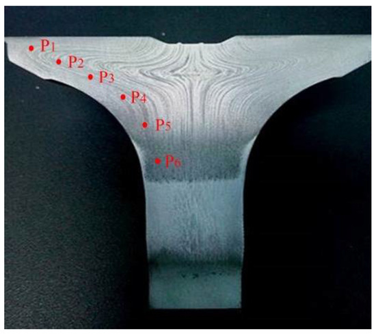
Figure 16.
Microstructure observation point of forging valve profile.
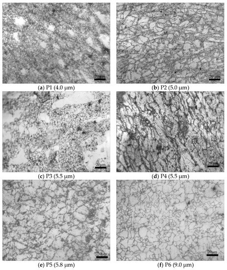
Figure 17.
Average grain size of 21-4N in the forging process 1–6.
7. Conclusions and Future Work
Systematic studies were conducted on the microstructure evolution of 21-4N for valve heads during forging. A set of unified viscoplastic constitutive equations for valves were established to predict the aforementioned microstructure evolution. The following conclusions are drawn.
(1) Hot compression deformation behavior and the microstructure evolution of 21-4N steel were investigated under different compression conditions. A static grain growth experiment was used to observe the static grain growth behavior of 21-4N steel.
(2) A set of unified viscoplastic constitutive equations were developed to describe the viscoplastic metal flow and microstructure evolution. Effective stress, average grain size, recrystallized fraction, and dislocation density were coupled as internal state variables of constitutive equations to reflect their interactive relationship and the physical evolution mechanism.
(3) Microstructure evolution was analyzed using the consolidated viscoplastic constitutive equations. The constitutive equation were realized by the commercial FE simulation software DEFORM-3D. The microstructural simulation of 21-4N during the forging process was carried out.
(4) Processing parameters, such as force and grain size of final valves, exert a significant effect on the forging process and the deformation behavior of materials. A fine grain structure was obtained in this work by analyzing the results of the numerical simulation and experimental data. The optimal forging temperature of 21-4N during valve forging is approximately 1060 °C. When the workpiece temperature is 1060 °C, the initial grain size is 10.4 μm, the grain size after forging is 3.6 μm, and the force is 1200 kN. The grain size is fine and the streamline is uniform.
(5) In the future: performance tests on valves after die forging will be carried out to determine whether valves can achieve the best performance. Then, the determined process parameters will be verified so as to determine the optimal process parameters.
Author Contributions
Conceptualization, H.J.; B.W.; Formal analysis, X.H.; Investigation, H.J., J.L.; Methodology, J.L., B.W.; Writing—original draft, H.J., C.M.; Writing—review & editing, X.H., W.P.
Acknowledgments
The authors thank the guidance from Jianguo Lin at Imperical College London. This work is supported by Yang Fan Innovative & Entepreneurial Research Team Project (No. 201312G02). This work is also supported by the National Natural Science Foundation of China (Grant No. 51505026, Grant No. 51375042).
Conflicts of Interest
The authors declare no conflict of interest.
References
- Zhu, Y.; Yin, Z.; Xu, J. Microstructural mapping in closed die forging process of superalloy Nimonic 80a valve head. J. Alloys Compd. 2011, 509, 6106–6112. [Google Scholar] [CrossRef]
- Jeong, H.S.; Cho, J.R.; Lee, N.K.; Park, H.C. Simulation of Electric Upsetting and Forging Process for Large Marine Diesel Engine Exhaust Valves. Mater. Sci. Forum 2006, 510–511, 142–145. [Google Scholar] [CrossRef]
- Ji, H.; Liu, J.; Wang, B.; Zhang, Z.; Zhang, T.; Hu, Z. Numerical analysis and experiment on cross wedge rolling and forging for engine valves. J. Mater. Process. Technol. 2015, 221, 233–242. [Google Scholar] [CrossRef]
- Voorwald, H.J.C.; Coisse, R.C.; Cioffi, M.O.H. Fatigue Strength of X45CrSi93 stainless steel applied as internal combustion engine valves. Procedia Eng. 2011, 10, 1256–1261. [Google Scholar] [CrossRef]
- Yu, Z.W.; Xu, X.L. Failure analysis and metallurgical investigation of diesel engine exhaust valves. Eng. Fail. Anal. 2006, 13, 673–682. [Google Scholar] [CrossRef]
- Biba, N.; Lishnij, A.; Vlasov, A. Simulation of coupled problem of electric upsetting. J. Mater. Process. Technol. 1998, 80, 184–187. [Google Scholar] [CrossRef]
- Jeong, H.S.; Cho, J.R.; Park, H.C. Microstructure prediction of Nimonic 80A for large exhaust valve during hot closed die forging. J. Mater. Process. Technol. 2005, 162–163, 504–511. [Google Scholar] [CrossRef]
- Chun, K.J.; Kim, J.H.; Hong, J.S. A study of exhaust valve and seat insert wear depending on cycle numbers. Wear 2007, 263, 1147–1157. [Google Scholar] [CrossRef]
- Ji, H.; Liu, J.; Wang, B.; Fu, X.; Xiao, W.; Hu, Z. A new method for manufacturing hollow valves via cross wedge rolling and forging: Numerical analysis and experiment validation. J. Mater. Process. Technol. 2017, 240, 1–11. [Google Scholar] [CrossRef]
- Jiang, H.; Yang, L.; Dong, J.; Zhang, M.; Yao, Z. The recrystallization model and microstructure prediction of alloy 690 during hot deformation. Mater. Des. 2016, 104, 162–173. [Google Scholar] [CrossRef]
- Wang, C.; Shi, D.; Yang, X.; Li, S.; Dong, C. An improved viscoplastic constitutive model and its application to creep behavior of turbine blade. Mater. Sci. Eng. 2017, 707, 344–355. [Google Scholar] [CrossRef]
- Sun, C.; Liu, G.; Zhang, Q.; Li, R.; Wang, L. Determination of hot deformation behavior and processing maps of IN 028 alloy using isothermal hot compression test. Mater. Sci. Eng. 2014, 595, 92–98. [Google Scholar] [CrossRef]
- Li, Y.; Zhao, S.; Fan, S.; Yan, G. Study on the material characteristic and process parameters of the open-die warm extrusion process of spline shaft with 42CrMo steel. J. Alloys Compd. 2013, 571, 12–20. [Google Scholar] [CrossRef]
- Xiao, J.; Li, D.S.; Li, X.Q.; Deng, T.S. Constitutive modeling and microstructure change of Ti–6Al–4V during the hot tensile deformation. J. Alloys Compd. 2012, 541, 346–352. [Google Scholar] [CrossRef]
- Lin, Y.C.; Deng, J.; Jiang, Y.; Wen, D.; Liu, G. Effects of initial δ phase on hot tensile deformation behaviors and fracture characteristics of a typical Ni-based superalloy. Mater. Sci. Eng. A 2014, 598, 251–262. [Google Scholar] [CrossRef]
- Chai, R.; Su, W.; Guo, C.; Zhang, F. Constitutive relationship and microstructure for 20CrMnTiH steel during warm deformation. Mater. Sci. Eng. A 2012, 556, 473–478. [Google Scholar] [CrossRef]
- Xiao, Y.; Guo, C. Constitutive modelling for high temperature behavior of 1Cr12Ni3Mo2VNbN martensitic steel. Mater. Sci. Eng. A 2011, 528, 5081–5087. [Google Scholar] [CrossRef]
- Chen, X.; Lin, Y.C.; Chen, M.; Li, H.; Wen, D.; Zhang, J.; He, M. Microstructural evolution of a nickel-based superalloy during hot deformation. Mater. Des. 2015, 77, 41–49. [Google Scholar] [CrossRef]
- Lin, Y.C.; Chen, M.; Zhong, J. Effect of temperature and strain rate on the compressive deformation behavior of 42CrMo steel. J. Mater. Process. Technol. 2008, 205, 308–315. [Google Scholar] [CrossRef]
- Lin, Y.C.; Chen, M.; Zhong, J. Constitutive modeling for elevated temperature flow behavior of 42CrMo steel. Comput. Mater. Sci. 2008, 42, 470–477. [Google Scholar] [CrossRef]
- Tang, X.; Wang, B.; Ji, H.; Fu, X.; Xiao, W. Behavior and modeling of microstructure evolution during metadynamic recrystallization of a Ni-based superalloy. Mater. Sci. Eng. A 2016, 675, 192–203. [Google Scholar] [CrossRef]
- Tang, X.; Wang, B.; Zhang, H.; Fu, X.; Ji, H. Study on the microstructure evolution during radial-axial ring rolling of IN718 using a unified internal state variable material model. Int. J. Mech. Sci. 2017, 128–129, 235–252. [Google Scholar] [CrossRef]
- Quan, G.; Mao, A.; Luo, G.; Liang, J.; Wu, D.; Zhou, J. Constitutive modeling for the dynamic recrystallization kinetics of as-extruded 3Cr20Ni10W2 heat-resistant alloy based on stress–strain data. Mater. Des. 2013, 52, 98–107. [Google Scholar] [CrossRef]
- Ji, H.; Liu, J.; Wang, B.; Tang, X.; Lin, J.; Huo, Y. Microstructure evolution and constitutive equations for the high-temperature deformation of 5Cr21Mn9Ni4N heat-resistant steel. J. Alloys Compd. 2017, 693, 674–687. [Google Scholar] [CrossRef]
- Li, N.; Sun, C.; Guo, N.; Mohamed, M.; Lin, J.; Matsumoto, T.; Liu, C. Experimental investigation of boron steel at hot stamping conditions. J. Mater. Process. Technol. 2016, 228, 2–10. [Google Scholar] [CrossRef]
- Huo, Y.; Bai, Q.; Wang, B.; Lin, J.; Zhou, J. A new application of unified constitutive equations for cross wedge rolling of a high-speed railway axle steel. J. Mater. Process. Technol. 2015, 223, 274–283. [Google Scholar] [CrossRef]
- Ma, W.; Wang, B.; Bian, J.; Tang, X.; Yang, L.; Huo, Y. A New Damage Constitutive Model for Thermal Deformation of AA6111 Sheet. Metall. Mater. Trans. A 2015, 46, 2748–2757. [Google Scholar] [CrossRef]
- Yang, L.; Wang, B.; Liu, G.; Zhao, H.; Xiao, W. Behavior and modeling of flow softening and ductile damage evolution in hot forming of TA15 alloy sheets. Mater. Des. 2015, 85, 135–148. [Google Scholar] [CrossRef]
- Tang, X.; Wang, B.; Zhang, N.; Huo, Y.; Zhou, J. Modeling of microstructural evolution and flow behavior of superalloy IN718 using physically based internal state variables. Rare Metals. 2015, 1–8. [Google Scholar] [CrossRef]
- Yang, L.; Wang, B.; Liu, G.; Zhao, H.; Zhou, J. Hot Tensile Behavior and Self-consistent Constitutive Modeling of TA15 Titanium Alloy Sheets. J. Mater. Eng. Perform. 2015, 24, 4647–4655. [Google Scholar] [CrossRef]
- Mohamed, M.S.; Foster, A.D.; Lin, J.; Balint, D.S.; Dean, T.A. Investigation of deformation and failure features in hot stamping of AA6082: Experimentation and modelling. Int. J. Mach. Tools Manuf. 2012, 53, 27–38. [Google Scholar] [CrossRef]
- Lin, J.; Liu, Y.; Farrugia, D.C.J.; Zhou, M. Development of dislocation-based unified material model for simulating microstructure evolution in multipass hot rolling. Philos. Mag. 2005, 85, 1967–1987. [Google Scholar] [CrossRef]
- Lin, J.; Dean, T.A. Modelling of microstructure evolution in hot forming using unified constitutive equations. J. Mater. Process. Technol. 2005, 167, 354–362. [Google Scholar] [CrossRef]
- Lin, J. A set of unified constitutive equations for modelling microstructure evolution in hot deformation. J. Mater. Process. Technol. 2003, 143–144, 281–285. [Google Scholar] [CrossRef]
- Sun, C.Y.; Guo, N.; Fu, M.W.; Liu, C. Experimental investigation and modeling of ductile fracture behavior of TRIP780 steel in hot working conditions. Int. J. Mech. Sci. 2016, 110, 108–115. [Google Scholar] [CrossRef]
- Gao, P.; Yang, H.; Fan, X.; Zhu, S. Unified modeling of flow softening and globularization for hot working of two-phase titanium alloy with a lamellar colony microstructure. J. Alloys Compd. 2014, 600, 78–83. [Google Scholar] [CrossRef]
- Cao, J.; Lin, J.; Dean, T.A. An implicit unitless error and step-size control method in integrating unified viscoplastic/creep ODE-type constitutive equations. Int. J. Numer. Methods Eng. 2008, 73, 1094–1112. [Google Scholar] [CrossRef]
- Cao, J.; Lin, J. A study on formulation of objective functions for determining material models. Int. J. Mech. Sci. 2008, 50, 193–204. [Google Scholar] [CrossRef]
- Huo, Y.; Lin, J.; Bai, Q.; Wang, B.; Tang, X.; Ji, H. Prediction of microstructure and ductile damage of a high-speed railway axle steel during cross wedge rolling. J. Mater. Process. Technol. 2017, 239, 359–369. [Google Scholar] [CrossRef]
- Ma, W.; Wang, B.; Fu, L.; Zhou, J.; Huang, M. Effect of friction coefficient in deep drawing of AA6111 sheet at elevated temperatures. Trans. Nonferrous Met. Soc. 2015, 25, 2342–2351. [Google Scholar] [CrossRef]
- Zhan, L.; Lin, J.; Dean, T.A. A review of the development of creep age forming: Experimentation, modelling and applications. Int. J. Mach. Tools Manuf. 2011, 51, 1–17. [Google Scholar] [CrossRef]


© 2018 by the authors. Licensee MDPI, Basel, Switzerland. This article is an open access article distributed under the terms and conditions of the Creative Commons Attribution (CC BY) license (http://creativecommons.org/licenses/by/4.0/).