Abstract
To improve the comprehensive performance of high speed steel (HSS) cold rolls, the induction hardening processes were analyzed by numerical simulation and experimental research. Firstly, a modified martensitic phase transformation (MMPT) model of the tested steel under stress constraints was established. Then, the MMPT model was fed into DEFORM to simulate the induction quenching processes of working rolls based on an orthogonal test design and the optimal dual frequency of the induction quenching process was obtained. The results indicate that the depth of the roll’s hardened layer increases by 32.5% and the axial residual tensile stress also becomes acceptable under the optimized process. This study provides guidance for studying phase transformation laws under stress constraints and the optimization of complex processes in an efficient manner.
1. Introduction
Work rolls of cold rolling, requiring high surface hardness, good thermal shock resistance, anti-stripping ability, and wear resistance, are usually produced using high carbon and high-alloy forged steel, such as Cr8 [1], D2 cold work tool steel [2], semi-highspeed steel (SHSS) [3], high speed steel (HSS) [4,5], etc. High speed steel has the best service performance among these materials.
To meet the above-mentioned performance requirements, work rolls of cold rolling are usually produced by fast heating via dual-frequency induction and subsequent rapid cooling. Thermal stresses and martensitic transformation stresses caused by volume expansion during the cooling process of rolls lead to large tensile stress locally and even quenching cracking [6,7,8,9]. Montalvo-Urquizo et al. investigated the mathematical model for the induction hardening process and summarized the simulation results. The change of the austenite–martensite phase was described using Schröder’s approach [10]. Tong et al. studied the induction heat treatment process using electromagnetic–thermal–transformation-mechanical coupled numerical simulations. The diffusional austenite decomposition (pearlite/bainite transformations) was neglected and the martensitic transformation was described using the K–M equation [11]. Fisk et al. demonstrated how to simulate the process of induction hardening using the commercial finite element software MSC Marc, together with experiment results. The transformation from austenite to martensite is also given by the K–M equation [12].
For small workpieces, the impact of stress on martensite phase transformation can be neglected; hence, the above models and methods of austenite–martensite phase transformation are applicable. However, for large workpieces, such as large rollers, martensite transformation occurs first on the surface and then gradually proceeds to the interior as the temperature decreases. The volume expansion caused by martensitic transformation leads to compressive stress in the phase change layer and tensile stress inside the workpiece. Therefore, the subsequent continuous martensitic transformation occurs under stress constraint. Basak and Levitas presented a finite element procedure for a new phase field approach to multivariant martensitic transformations at large strains and with interfacial stresses induced by temperature and stress [13]. Yen et al. explained the impact of stress-assisted martensite on the occurrence of transformation-induced plasticity, and proved thatα’-martensite nucleation by a stress-assisted process accounted for the transformation-induced plasticity in ultrafine-grained austenite. [14]. Liu et al. systematically studied the impact of uniaxial compressive stress on the kinetics of the austenite–martensite transformation and presented a modular phase-transformation model [15].
There are many factors affecting induction hardening of large rolls, such as preheating temperature, current frequency, workpiece moving speed, and so on [10,11,12]. To reduce the cost and the number of experiments, numerical simulations and experiments are usually used to study the complex experimental process with the aid of an orthogonal experimental design [16,17], random design, uniform design [18,19], and so on. In this work, a modified martensitic phase transformation model of the tested HSS was obtained using a physical simulation on aGleeble-3500 thermal–mechanical simulator and using microstructure analysis. Then, the dual frequency induction hardening processes were systematically studied using numerical simulations and experiments, based on an orthogonal experimental design. Finally, the parameters of the induction hardening process were optimized.
2. Experimental Materials and Methods
2.1. Materials andCooling Tests with Loads
The experimental material was a new forged high speed steel for cold rolling work rolls. The chemical composition (wt%) was 1.15–1.30 C, 0.10–0.40 Si, 0.10–0.40 Mn, 9.50–15.40 Cr, 1.50–2.50 Mo, 1.60–4.30 V, and 1.30–1.60 W. The Ac1 and Acm temperatures were 876 and 951 °C, respectively, while the Ms temperature was 160 °C. The experimental specimens were annealed at 750 °C before the induction hardening test to reduce the residual stress.
To build the martensitic transformation model in the induction heating process of the roller, several martensitic transformation processes under stress constraint were simulated on a thermal–mechanical simulator Gleeble-3500 (DSI, Poestenkill, NY, USA). The specimens, with sizes of 10 mm × 15 mm, were rapidly heated to a quenching temperature of 1000 °C and held for 5 min to ensure the uniformity. Then, the specimens were cooled to room temperature with a cooling rate of 10 °C/s, which were compressed with stresses of 0.1, 0.2, 0.3, and 0.4 Rm (the peak value of the compression strength) at temperatures of 160, 180, and 200 °C, respectively. The peak values of the compression strengths of the tested steel at 160, 180, and 200 °C were 1740, 1700, and 1665 MPa, respectively.
2.2. Quantitative Phase Analysis
The Value K method of X-ray diffraction was used to analyze the phase content of the specimens in cooling tests with loads, as well as the trial roll produced using the optimized dual frequency induction quenching process. The cooled specimens were sliced along the longitudinal direction. The specimens were prepared by hand grinding and the mesh numbers of the grinding papers are 120, 280, 500, 800, and 1200. The samples were held tightly by hand and pressed on the grinding face of the paper, evenly and lightly, and then polished in a single direction. The grinding paper was replaced when the front track abrasion marks disappeared completely. After replacing the grinding paper, the sample was rotated 90° to continue grinding. After hand grinding, the specimens were mechanically polished on a polishing machine and the polishing compound was a diamond polishing paste with a size of 1.5–1.0 µm. Then, the polished specimens were revealed by using 4 wt% Nital etching for 9 s. Phase content of the above compressed specimens were measured on an X-ray diffractometer D/max-2500/PC (Rigaku Corporation, Tokyo, Japan) with Cu radiation. Two different cross sections of each kind of material analyzed were measured. The corresponding measured value was the average value of the two cross sections. The scanning speed was 4°/min. The light tube voltage and filament current were 40 kV and 250 mA, respectively. Jade-6 software (Hong Kong, China) was used to analyze the experimental data and determine the phase type, structure, and content of each phase.
2.3. Determinations of Thermophysical Parameters
For the tested forged high speed steel, the tensile strength, Rm and yield strength, Rel were measure by compression test on a thermal-mechanical simulator Gleeble-3500. The dimensions of specimens were Φ8 mm × 15 mm. The heating and strain rates were 5 °C/s and 0.001 s−1. The elastic modulus, E and Poisson ratio, v was measured on a universal testing machine according to the GB/T 22315-2008 standard. The linear expansion coefficients, α was measured on a dilatometer Formastor-F and the dimensions of specimens were Φ8 mm × 15 mm. The specific heat was measured by using a NETZSCH differential scanning calorimeter (NETZSCH, Selb, Germany) and the dimensions of the specimens were Φ3 mm × 1.5 mm. The heating rate was 5 °C/min. The thermal conductivity was measured on a TC-7000 laser flash thermal constant measuring apparatus and the dimensions of the specimens were Φ10 mm × 2 mm.
3. Experimental and Modelling Results
3.1. Results of X-Ray Diffraction
The X-ray diffraction spectra are shown in Figure 1. The Value K method was adopted to calculate the content of martensite and retained austenite in the specimens. The diffraction spectra (a, b, c, and d) in Figure 1 correspond to 0.1, 0.2, 0.3, and 0.4 Rm, at each loading temperature. It can be known from Figure 1 that the content of martensite increases with the increasing loads and decreasing loading temperatures.
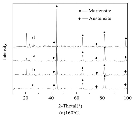
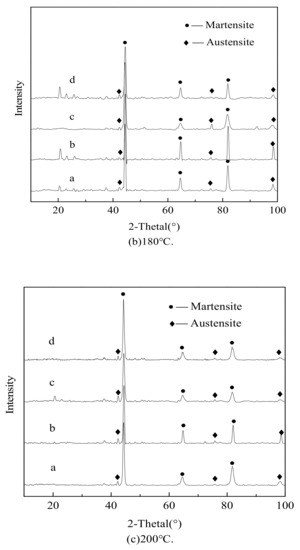
Figure 1.
Spectra under different stresses at different temperatures; (a) 160 °C; (b) 180 °C; (c) 200 °C.
3.2. Establishment of the Martensitic Transformation Model
The martensitic transformation belongs to the non-diffusive phase transformation. The volume fraction of the phase change mainly depends on the temperatures, the applied loads and the content of carbon. According to the modified Magee equation, the formula for the calculation model of the martensite volume fraction is expressed as follows,
where ξM, T, , , C, and C0 are the martensite fraction, temperature, equivalent stress, mean stress, diffused carbon content, and the design content of carbon, respectively., , , , and are constant parameters. The units of the stress and temperature are Pa and K, respectively. The unit of is K−1. The units of and are Pa−1, while the parameters and are unit-less. In this work, no carbon diffusion occurred, so . Then,
ABAQUS finite element software (ABAQUS 6.10, Dassault, Paris, France), was used to obtain the equivalent stress and the mean stress of the specimens during cooling transformation processes with applied loads. The element type was C3D8. The simulated equivalent stress and average stress are shown in Table 1. After simplification, polynomial regression analysis was carried out by using Origin 9.0 software (OriginLab, Northampton, MA, USA) and four parameters were obtained, and the fitted Magee equation is shown as follows,

Table 1.
Parameters used for building martensite phase transformation model.
The calculated value and relative error of the martensite transformation content are shown in Table 1. The fitting values are larger than the measured ones. When the temperature is fixed, the relative error increases gradually with the increasing loads, but the relative errors are all below 5.65%, with the average at 3.36%, which indicates that the modified martensitic transformation model in this work is reasonable.
4. Simulation and Optimization Design of Induction Hardening Processes
For the dual frequency induction hardening processes of large work rolls in cold rolling, the main factors affecting the mechanical properties and service performance after quenching include the preheating temperature, frequency of dual frequency coils, cooling intensity of the quenching medium, moving speed of the working roll during induction hardening, environment temperature, and so on. Combined with the influence of the above factors on induction hardening processes, L16(45) orthogonal tables were adopted in the orthogonal tests of this work, as shown in Table 2. The length and diameter of the simulated roll are 4370 and 470 mm, respectively. The simulation model and experiment equipment are shown in Figure 2. It was assumed that the preheating temperature of quenching test was uniform. Based on the martensite phase model obtained in this work, the dual frequency induction hardening processes listed in Table 2 were simulated using DEFORM-3D software, which allowed the parameters in Equation (1) to be input and modified. The stable current densities of the induction coil I and IIare 2650 and 3286 A·m−2, respectively. The thermophysical parameters of the tested steel are listed in Table 3.
Table 2.
Factors and levels of orthogonal experiment design.
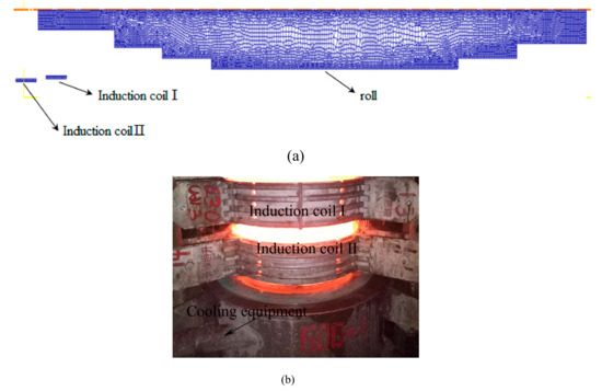
Figure 2.
(a) Finite element model of the dual frequency induction process and (b) experimental set-up.
Table 3.
Thermo physical parameters.
5. Simulated Results and Analyses of Orthogonal Tests
The depth of the hardened layer and the maximum axial stress of each factor combination are obtained by using FEM simulation, as shown in Table 4. Based on the simulated results of the depth of the hardened layer and maximum axial tensile stresses, sums of level values Tij, the average of level values , and max–min difference values R are listed in Table 5.
Table 4.
L16 (45) orthogonal level list and simulated indexes.
Table 5.
Analysis of ranges of orthogonal results.
For work rolls of cold rolling, adequate depth of the hardened layer is very important. It is known from Table 5 that TA1 is the smallest one between the four level values of preheating temperatures. The depth of the hardened layer and the axial tensile stress increases by increasing the preheating temperatures. In addition, the biggest of the four level values of moving speeds of induction coils was TB1. The depth of the hardened layer decreased with increasing moving speeds of induction coils and increased with increasing cooling intensity in general. When the cooling intensity is above 6000 W·m−2·°C−1, the depth of the hardened layer changed a little by increasing the cooling intensity. The reason may be that the internal temperature drops of the roll mainly depend on its heat conduction, but subject to a slight impact from the surface temperature. For factor D and E, the depth of the hardened layer increases with the increasing frequencies of dual frequency coils. Combining the max-min difference values R of the five factors, the order of factors is A > B > D > E > C.
The influence of these five factors on the maximum axial tensile stress has the same rule with that on the depth of hardened layer. By increasing the depth of hardened layer, the expansive volume of the martensite transformation layer increased and bigger compressive stresses occurred on the martensitic transformation layer. Martensitic transformation did not occur in the center of the roll. To achieve stress balance, a bigger axial tensile stress appeared in the inner part of the roll.
When the depth of the hardened layer is used as the index, the best induction process is A4B1C4D4E4. When the axial stress is taken as the index, the best induction process is A1B4C1D1E1. For work rolls of cold rolling, to ensure that the tensile stress of the quenching process does not cause cracking in the roll, it is necessary to control the depth of the hardened layer. For large work rolls of cold rolling, the hardened layer is usually required no less than 70 mm.
In order to analyze the influence of different factors on indexes in general, the main effect diagrams of the hardened layer depth and the axial tensile stress are shown in Figure 3.In Figure 3a,b, A1 is the average value of the depth of hardened layer or maximum axial tensile stress of the orthogonal tests No.1–4 in Table 4, which has the same level 1 (300 °C) for factor A (preheating temperatures). The same is true for other factors B–E in Figure 3. The hardened layer depth and maximum axial tensile stress of the roll increase with increasing the preheating temperature rises and the frequency of the two coils. The above two indexes are inversely proportional to the moving speed of coils, which are not affected prominently by cooling intensity. To obtain enough hardened layer depths, small axial tensile stresses, and higher heating efficiency, the optimized roll induction hardening process is A3B2C4D4E4, that is, the preheating temperature is 500 °C, the roll moving speed is 0.7 mm/s, the cooling intensity is 10,000 W·m−2·°C−1, and the frequencies of the two coils are 75 and 250 Hz, respectively.
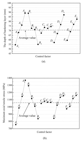
Figure 3.
Main effect diagram of (a)the depth of hardened layer and (b) maximum axial tensile stress.
6. Optimization Results Analysis
The conventional dual frequency induction quenching processes of the tested cold work roll shave the preheating temperatures of 350 °C, moving speeds of coils of 0.7 mm/s, cooling intensity of 6000 W·m−2·°C−1, and the frequencies of the two coils of 75 and 250 Hz, respectively. The conventional and optimized dual frequency induction quenching processes are simulated by using DEFORM-3D v10.2 software. The simulated residual axial stress and the volume fraction of martensitic hardened layer are shown in Figure 4 and Figure 5, respectively. The measured martensite contents of the actual work rolls of cold rolling produced by the conventional and optimized dual frequency induction quenching processes are shown in Figure 6.
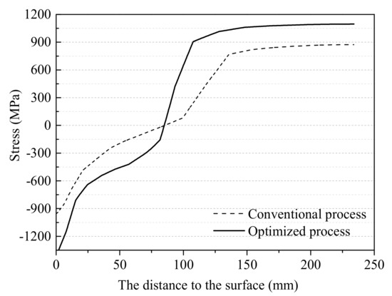
Figure 4.
The residual axial stress distribution curves.
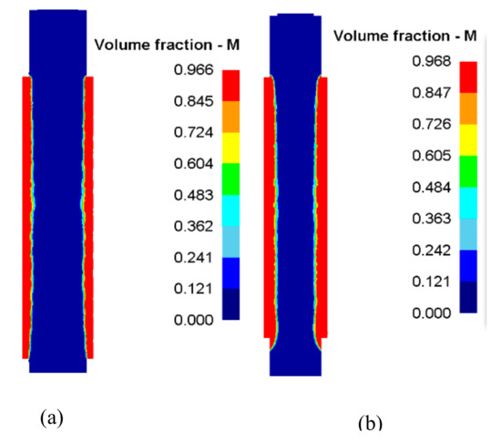
Figure 5.
Simulated martensitic hardened layer under (a) the conventional and (b) optimized processes.
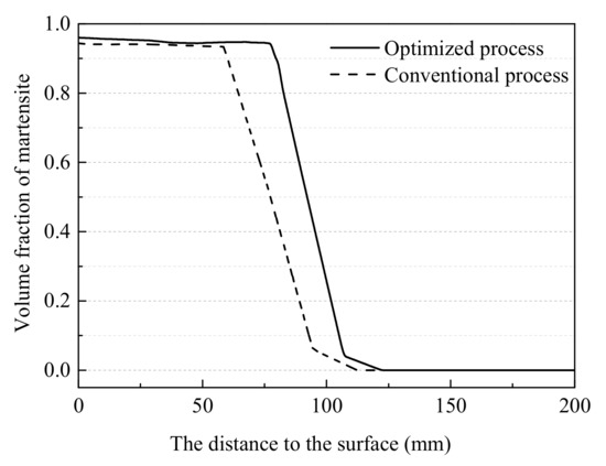
Figure 6.
Measured martensite distribution curves.
As shown in Figure 4, the simulated residual axial stress distributions of the work rolls of cold rolling produced by the above conventional and optimized dual frequency induction quenching processes are similar. Compressive stresses are present in the surface hardened layer, while tensile stresses in the inner part of the roll. The maximum axial residual tensile stress under the optimized process is about 1100 MPa, while the one under the conventional process is about 900 MPa.
From Figure 5 and Figure 6, the hardened layer (with martensite content greater than 90%) and the transition layer under the optimized process are thicker and more uniform than those under the conventional process. The depth of the hardener layer increases from 60 mm to 79.5 mm by optimizing the parameters of the dual frequency induction quenching process parameters. The reason is that the preheating temperature of the working roll and the cooling intensity has been raised under the optimized process. Then, the depth of complete austenite layer increases, which lead to the increase in the depth of the quenched layer after the dual frequency induction quenching.
The maximum residual tensile stress obtained under the optimized induction hardening process is bigger than that under the conventional process but smaller than the tensile strength of the tested steel. Then, no cracks appear in the inner part. The residual compressive stress in the surface hardened layer of the work roll in cold rolling under the optimized induction quenching process is also bigger than that under the conventional process because of more martensitic transformation accumulation as shown in Figure 5 and Figure 6. The residual stresses in the cold rolling work roll produced by dual frequency induction quenching is usually improved by the tempering process, which make the surface compressive stresses and the inner tensile stresses smaller. In addition, the presence of appropriate residual compressive stresses on the surface layer is beneficial to improve the service performance of the roll.
7. Conclusions
- (1)
- The thermal stress and phase transformation stress can promote the martensite transformation of the tested high carbon roll steel. The modified Magee equation of the tested steel is .
- (2)
- The orthogonal test was designed with the help of five factors four levels orthogonal table to optimize the hardened layer depth and the axial tensile stress in dual frequency induction quenching processes. The optimal combination was found out by the orthogonal analysis. The results show that the effect of preheating temperatures on hardened layer depth and the axial tensile stress is the largest, while the effect of cooling intensity is the least.
- (3)
- The simulation and industrial test studies of the optimized and conventional dual frequency induction quenching processes show that the hardened layer depth is increased by 32.5% and the maximum residual axial tensile stress reaches about 1100MPa in the optimized process, which is acceptable. The simulated and measured depths of the hardened layer coincide with each other, further which indicates the correctness of the phase transition model obtained in this study furtherly.
Author Contributions
L.L. wrote the paper; H.Y. analyzed the experiment data; Z.Y. performed the cooling experiments under stress constraints; C.Z. validated the results of experiments; T.Z. conceived and designed the experiments.
Acknowledgments
This work was supported by Natural Science Foundation of Hebei Province of China No. E2016203217 and National Natural Science Foundation of China No.51205342.
Conflicts of Interest
The authors declare no conflict of interest.
References
- Chi, H.X.; Ma, D.S.; Yong, Q.L.; Wu, L.Z.; Zhang, Z.P.; Wang, Y.W. Effect of cryogenic treatment on properties of Cr8-type cold work die steel. J. Iron Steel Res. Int. 2010, 17, 43–46. [Google Scholar] [CrossRef]
- Kang, J.Y.; Kim, H.; Son, D.; Kim, C.; Park, S.K.; Lee, T.H. Hot-worked microstructure and hot workability of cold-work tool steels. Mater. Charact. 2018, 135, 8–17. [Google Scholar] [CrossRef]
- Wang, M.J.; Wang, Y.; Sun, F.F. Tempering behavior of a semi-high speed steel containing nitrogen. Mater. Sci. Eng. A 2006, 438–440, 1139–1142. [Google Scholar] [CrossRef]
- Guo, J.; Liu, L.G.; Li, Q.; Sun, Y.L.; Gao, Y.K.; Ren, X.J.; Yang, Q.X. Characterization on carbide of a novel steel for cold work roll during solidification process. Mater. Charact. 2013, 79, 100–109. [Google Scholar] [CrossRef]
- Guo, J.; Liao, B.; Liu, L.G.; Li, Q.; Ren, X.J.; Yang, Q.X. Forging limit of a novel high-speed-steel cold work roll based on ductile fracture criteria by finite element model. Mater. Des. 2013, 52, 1027–1034. [Google Scholar] [CrossRef]
- Šolić, S.; Podgornik, B.; Leskovšek, V. The occurrence of quenching cracks in high-carbon tool steel depending on the austenitizing temperature. Eng. Fail. Anal. 2018, 92, 140–148. [Google Scholar] [CrossRef]
- Wu, H.; Udagawa, Y.; Narukawa, T.; Amaya, M. Crack formation in cladding under LOCA quench conditions. Nucl. Eng. Des. 2016, 303, 25–30. [Google Scholar] [CrossRef]
- Xiong, Z.P.; Jacques, P.J.; Perlade, A.; Pardoen, T. Ductile and intergranular brittle fracture in a two-step quenching and partitioning steel. Scr. Mater. 2018, 157, 6–9. [Google Scholar] [CrossRef]
- Ju, Y.; Koyama, M.; Sawaguchi, T.; Tsuzaki, K.; Noguchi, H. Effects of ε-martensitic transformation on crack tip deformation, plastic damage accumulation, and slip plane cracking associated with low-cycle fatigue crack growth. Int. J. Fatigue 2017, 103, 533–545. [Google Scholar] [CrossRef]
- Montalvo-Urquizo, J.; Liu, Q.; Schmidt, A. Simulation of quenching involved in induction hardening including mechanical effects. Comp. Mater. Sci. 2013, 79, 639–649. [Google Scholar] [CrossRef]
- Tong, D.M.; Gu, J.F.; Yang, F. Numerical simulation on induction heat treatment process of a shaft part: Involving induction hardening and tempering. J. Mater. Process. Technol. 2018, 262, 277–289. [Google Scholar] [CrossRef]
- Fisk, M.; Lindgren, L.E.; Datchary, W.; Deshmukh, V. Modelling of induction hardening in low alloy steels. Finite Elem. Anal. Des. 2018, 144, 61–75. [Google Scholar] [CrossRef]
- Basak, A.; Levitas, V.I. Finite element procedure and simulations for a multiphase phase field approach to martensitic phase transformations at large strains and with interfacial stresses. Comput. Methods Appl. Mech. Eng. 2019, 343, 368–406. [Google Scholar] [CrossRef]
- Yen, H.W.; Ooi, S.W.; Eizadjou, M.; Breen, A.; Huang, C.Y.; Bhadeshia, H.K.D.H.; Ringer, S.P. Role of stress-assisted martensite in the design of strong ultrafine-grained duplex steels. Acta Mater. 2015, 82, 100–114. [Google Scholar] [CrossRef]
- Liu, Y.C.; Liu, C.X.; Sommer, F.; Mittemeijer, E.J. Martensite formation kinetics of substitutional Fe-0.7 at.% Al alloy under uniaxial compressive stress. Acta Mater. 2015, 98, 164–174. [Google Scholar] [CrossRef]
- Jiang, B.; Wu, M.; Zhang, M.; Zhao, F.; Zhao, Z.G.; Liu, Y.Z. Microstructural characterization, strengthening and toughening mechanisms of a quenched and tempered steel: Effect of heat treatment parameters. Mater. Sci. Eng. A 2017, 707, 306–314. [Google Scholar] [CrossRef]
- Liu, Q.B.; Liu, H. Experimental study of the laser quenching of 40CrNiMoA steel. J. Mater. Process. Technol. 1999, 88, 77–82. [Google Scholar]
- Gu, S.; Xu, G.Q.; Quan, Y.K.; Yuan, Q.C.; Davies, P.A. Uniform design for the optimization of Al2O3 nanofilms produced by electrophoretic deposition. Surf. Coat. Technol. 2016, 286, 268–278. [Google Scholar]
- Yang, J.; Li, L.; Yang, L.Y.; Li, J.Q. Uniform design for the parameters optimization of pin-fins channel heat sink. Appl. Therm. Eng. 2017, 120, 289–297. [Google Scholar] [CrossRef]


© 2019 by the authors. Licensee MDPI, Basel, Switzerland. This article is an open access article distributed under the terms and conditions of the Creative Commons Attribution (CC BY) license (http://creativecommons.org/licenses/by/4.0/).