Abstract
In a situation where a fire occurs either in a tunnel with a burning vehicle carrying petroleum products, at an offshore platform, or at an oil and gas asset to be protected, such a case is commonly described using a hydrocarbon fire curve. Therefore, it is extremely important to design construction, which can maintain stability and bearing capacity both under the standard and hydrocarbon fire modes. The purpose in this work is to hold a behavior simulation of a steel structure with fireproofing ensured through lightweight concrete slabs reinforced with fiber glass as well as a validation of the outcomes by assessing the experimental findings obtained from the relevant fire tests. A fire resistance study was carried out here for steel structures with a profile ratio of 156 mm−1 for the cases of a standard fire and of a hydrocarbon fire. A constant static load of 687 kN (70 tf) was taken for standard fire and 294 kN (30 tf) for hydrocarbon fire; the column was under vertical compression with one end resting on a hinged support and the other end rigidly fixed. The specimen design incorporated single-layer box-section cladding made of Pyro-Safe Aestuver T slabs, 40 mm thick and of a 650 kg/m3 density, pre-cut to fit the column size. The column strength loss (R) ultimately occurred after 240 min in the standard fire case and after 180 min in the hydrocarbon fire case. As the breach in the fireproofing structural integrity (E) or the installation accuracy cannot be considered, the limit state indicators may show certain discrepancies. According to the simulation performed using SOFiSTiK software, the design fire resistance rating of the structure in a hydrocarbon fire case was 58% higher than the figure obtained by holding fire tests due to the slabs cracking during the experiment session; the discrepancy between the outcomes of the session and the simulation in a standard fire case was as much as 15%.
1. Introduction
Structural fire protection is an integral part of construction engineering as it directly impacts the safety of people and the structures’ compliance with the fire resistance rating and therefore the structural stability in case of fire. The fire protection of process units used in the upstream and midstream production and shipping of oil, natural gas, and petroleum products and the protection of bearing structures of road and railroad tunnels and bridges have recently become increasingly urgent. A fire occurring in a tunnel or under a bridge involving a burning vehicle carrying petroleum products, or a fire on an offshore platform, or at an oil and gas asset to be protected, entails severe local fire impact on the bearing structure and is most often described using a hydrocarbon fire curve [,,,,,], as stipulated in EN 1363-2:1999 [] (Figure 1).
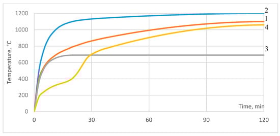
Figure 1.
Fire curves according to EN 1363-2:1999 []: 1—standard time-temperature curve; 2—hydrocarbon curve; 3—external fire exposure curve; 4—slow heating curve.
One of the crucial design indicators defining the fire safety assurance level for buildings and facilities is the structural fire resistance rating, i.e., the time since the fire impact starts (minutes, standard testing conditions) or the calculated time period until either one or a sequence of limit state indicators are reached (R, E, I) []. For bearing steel structures, the fire resistance rating is defined under standard trial conditions using methods set in the fire safety regulatory documents, considering the limit state indicator, i.e., loss of bearing capacity (R). The standard EN 1363-2:1999 [] determined certain fire cases for which the said tests are to be performed (Figure 2). In most countries, the structural fire resistance testing methods are harmonized and are based on the international ISO 834 [].
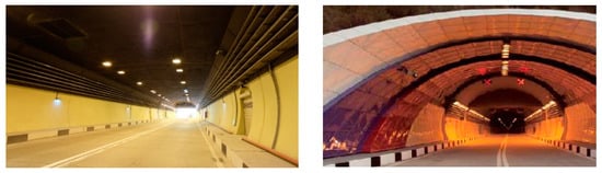
Figure 2.
Roki road tunnel through the main Caucasian ridge (North Ossetia) with fireproofing ensured using Pyro-Safe Aestuver T slabs, 2013–2014.
Due to limited evacuation possibilities and complicated access to the seat of the fire, fire safety assurance measures need to be duly elaborated and incorporated. One such action, namely passive fire protection for the structural steel in tunnels, implies considerably high fire resistance ratings for such structures (R120, R150, or R180 min) according to [] (Figure 2). Depending on the functions and the design solutions adopted for the buildings and structures (industrial facilities, high-rise buildings, etc.), the structural fire resistance rating can go up to 240 or 360 min [].
High as these fire resistance rating values are, they can be reached only by implementing structural fire protection means: plaster compounds, slabs made of various non-flammable materials, such as rockwool, etc. The cutting-edge solutions encompass slabs based on cementitious binder, carbon fiber, and fiber glass with high alkali resistance as reinforcing component, and perlite/vermiculite as a lightweight aggregate [,].
This article includes references to outcomes of fire tests held with nonflammable structural protection, namely Pyro-Safe Aestuver T slabs (manufacturer by Prozask LLC) produced from lightweight cement reinforced with fiber glass, and various aggregates, primarily perlite with its bulk density of 690 kg/m3 (if dry). The Pyro-Safe Aestuver T slabs have proven to perform as a means of fire protection for road tunnel and subway lining, as well as fire protection for steel and cast in situ structures of oil and gas assets (Figure 2 and Figure 3).
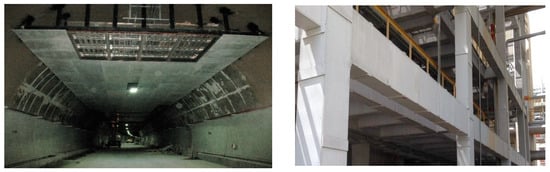
Figure 3.
Fire protection of tunnel structural steel with Pyro-Safe Aestuver T slabs cladding. (Left): Fire protection in Tunnel 1, relief road for Kurortny Avenue, city of Sochi, 2011–2012; (Right): structural steel protection at Taneco refinery plant, city of Nizhnekamsk, 2013–2017.
In order to implement the new means of fire protection, permit documents need to be obtained and standardized fire tests to be performed that would verify the fire resistance rating values specified by the manufacturer. To hold a fire test is a labor-intensive and costly activity, and therefore the mathematic simulation of structural steel heating up to critical temperatures under fire impact and the defining of stresses and deformation in the structural elements are becoming more and more involved in engineering. Simulation allows us to select the relevant thickness and the amount of fireproof material, in line with the design loads and the structural section ratio without series of expensive fire tests. It drastically reduces the time required to prepare the design documents and project cost.
The finite-element method, being a numeric technique of solving differential equations with partial derivatives and integral equations as part of solving the applied physics problems, has the greatest practical meaning among the aforementioned simulation methods. There is wide selection of software complexes in the engineering practice that allow us to implement the finite-element method [,,,,]. In our investigation, the modelling was performed by using the SOFiSTiK program [], a product offering an ambitious range of simulation options as related to structures, boundary conditions, and loads.
The purpose here is to determine by experiment the fire resistance ratings of columns formed by steel structures with Pyro-Safe Aestuver T fireproofing slabs in a standard fire case and a hydrocarbon fire case, as well as to simulate the behavior of the structures incorporating this type of protection, using the SOFiSTiK software complex, in order to forecast the possibility of achieving higher fire resistance ratings by applying this structural fireproofing.
2. Materials and Methods
A steel column with fireproof cladding was fire-tested under both standard fire and hydrocarbon fire. Standard fire temperature is defined by the following dependence []:
T − T0 = 345∙lg(8t + 1)
For hydrocarbon fire, the temperature is defined by the following dependence []:
where T means the temperature inside the furnace in °C, corresponding to the relevant time t; T0 is the temperature in °C inside the furnace prior to the start of heat impact (ambient temperature); and t is the time in min from the start of the test.
T = 1080∙(1 − 0.325 e−0.167t − 0.675 e−2.5t) + 20
SOFiSTiK software was used to assess the temperature distribution on the section of the columns while simulating the fire impact.
2.1. Columns Fire Testing
Each test involved two test specimen items for each of the fire types (four specimens in compliance with the standards [,]). As specimens, I-beams were taken, their height being (3000 ± 10) mm, their profile 30K1 per ASChM 20-93 (a standard adopted by the Association of Enterprises and Entities for Standardizing Iron and Steel Products, Russia), with the column steel’s effective thickness at 6.4 mm (a profile ratio of 156 mm−1). The trial column heads and pedestals were made of steel plates 300 × 300 × 20 mm (length × width × thickness, steel grade C345-3 []).
The cladding design of the test specimens was composed of Pyro-Safe Aestuver T slabs, of a 40 mm thickness and a density of 650 kg/m3 ± 10%, pre-cut to fit the column size and installed in a single-layer arrangement with a box-shaped section, which also includes slab stripes, 10 mm thick, and of a density 980 kg/m3 ± 10%. The stripes of the slabs, 100 ± 10 mm wide, were attached to each other using brackets, and they formed belts around the columns used as pads under the junctions of main fireproof cladding slabs (Figure 4, Figure 5, Figure 6 and Figure 7).
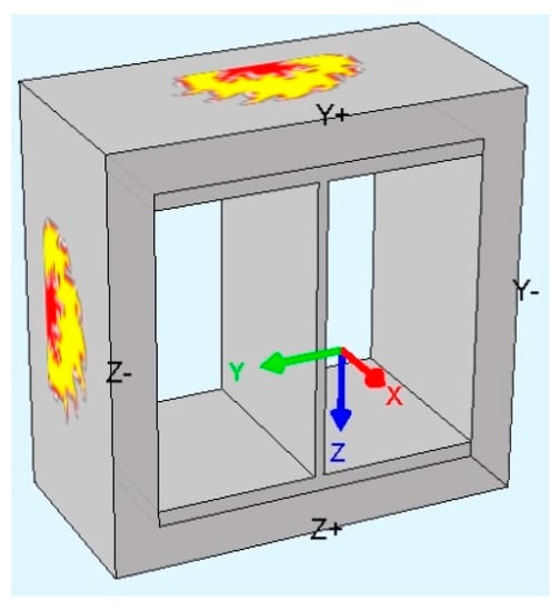
Figure 4.
Visual appearance of the structure simulated in SOFiSTiK.
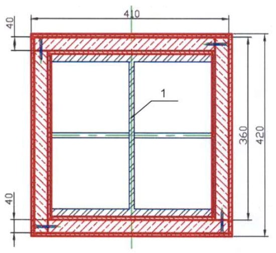
Figure 5.
Test specimen design.
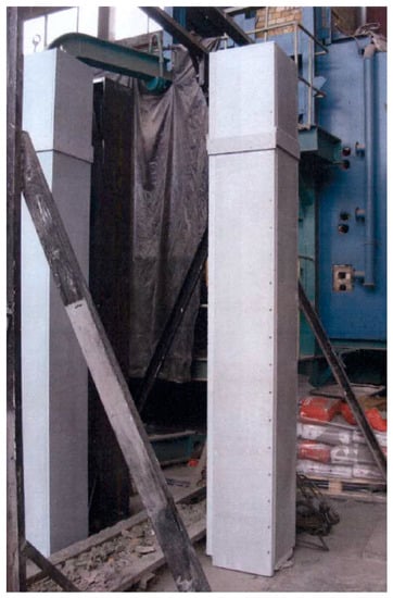
Figure 6.
Steel column test specimens with fireproof slabs cladding.
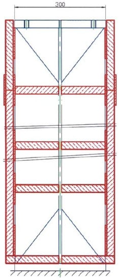
Figure 7.
Assembly pattern of the fire protection cladding.
With the belts and the stiffeners installed, the 40 mm thick slabs were fastened and aggregated using 6 × 90 mm self-tapping screws set into the slabs’ end parts with a (200 ± 10) mm pitch to form the box-shaped section cladding.
For vertical bearing frame structures, the limit states while holding a fire resistance test per cl.8.2 [], are outlined as follows: loss of bearing capacity (R) due to the structure collapse or a critical strain, where the critical vertical deformation for this column is 30 mm, and the rate of the critical vertical deformation rise is more than 10 mm/min [].
The temperature inside the furnace firebox was measured with the furnace thermocouples evenly distributed in six points along the height of the test specimen, while the temperature on the specimen was measured by three thermocouples installed in the midsection of the I-beam web and on the inner surface of the I-beam flanges. The specimens were put inside the firebox and exposed to heat impact from four sides.
The tests were held with a constant static load of 687 kN (70 tf) in the standard fire case and 294 kN (30 tf) in the hydrocarbon fire case, under vertical compression, with one end resting on a hinged support and the other end rigidly fixed. The strength loss or stability loss of the steel structures correlates with a certain heating temperature of the steel referred to as critical temperature. Calculating the fire resistance threshold (limit) implies resolving a static problem and a heat-engineering problem at the same time. To solve the static problem means to define the bearing capacity of the structure, considering the changing characteristics of the steel under high temperatures, i.e., to define the critical temperature when the fire limit state is reached. Here, we define the critical temperature of the column steel structure under study.
The column structure suffers from centric compression, with the load at 70 tf with the standard fire and 30 tf with the hydrocarbon fire.
Figure 8 and Table 1 show the 30K1 I-beam dimensions and the thermocouples arrangement comprising three pieces (i.e., in the midsection of the specimen, on the I-beam web, and on the inner surface of the I-beam).
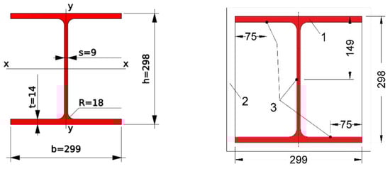
Figure 8.
Dimensions of the 30K1 I-beam profile (left) and thermocouples arrangement (right).

Table 1.
Characteristics of the 30K1 I-beam profile.
2.2. Simulation in SOFiSTiK Software
The ratio γT and ratio γe for the structure under study are calculated depending on the load type. For elements under centric compression, the following are used [,,]:
where Nn means design loading force in kg; F is the cross-sectional area of the shaft in cm2; Ryn is the initial characteristic resistance of the steel in kg/cm2 (for C345 steel, 3250 kg/cm2); En is the initial metal elastic modulus in kg/cm2 (for steel, En = 2,100,000 kg/cm2); lef is the design shaft length in cm; Imin is the least moment of the shaft section in cm4.
γT = Nn/(F∙Ryn)
γe=(Nn∙lef2)/(π2∙En∙Imin)
Here, the design length of the shaft is taken as 0.7∙l if one end one end is rigidly fixed and the other has a hinged support.
Standard fire:
γT = 70,000/(110.8 ∙ 3250) = 0.194
γe = (70,000∙(300∙0.7)^2)/(π^2 ∙ 2,100,000 ∙ 6240.9) = 0.02
Hydrocarbon fire:
γT = 30,000/(110.8 ∙ 3250) = 0.083
γe = (30,000∙(300∙0.7)^2)/(π^2 ∙ 2,100,000 ∙ 6240.9) = 0.01
In compliance with [,], the critical temperature of the shaft () is defined as the lowest value of the two values found, depending on the and ratios.
With the ratio values known, the values of the steel critical temperature () can be defined for the limit state of the structure under fire using this formula:
| tcr = 750 − 440∙γT, when γT < 0.6 |
| tcr = 1330∙(1 − γT), when γT ≥ 0.6 |
For the standard fire, tcr = 665 °C, while for the hydrocarbon fire, tcr = 713 °C. Characteristics of the materials set for the simulation purposes are specified in Table 2 and Table 3.
Table 2.
Physical characteristics of steel grade S345.
Table 3.
Physical characteristics of fire protection.
During the heating, the materials change their thermal conductivity and heat capacity. In line with [], straight line correlations are applied:
where A means initial thermal conductivity ratio in W/(mK), B means the ratio of thermal conductivity variation during the heating in W/(m∙K2), and T means heating temperature of the material in K.
where C means the initial heat capacity ratio in J/(kg∙K), D means the ratio of heat capacity variation during the heating in J/(kg∙K2), and T means the heating temperature of the material in K.
λt = A + B∙T
ct = C + D∙T
As previously mentioned, the Pyro-Safe Aestuver T structural fire protection consists of lightweight concrete slabs reinforced with fiber glass. Due to not having sufficient thermophysical characteristics of the fire protection indicated in the manufacturers’ technical documents, we took an average value of lightweight concrete characteristics provided in the engineering and scientific works [] for simulating slab-based fireproofing (Table 4).
Table 4.
Coefficients of thermal conductivity and heat capacity of the materials.
Outcomes of SOFiSTiK simulation offer the following temperature distribution patterns (Figure 9).
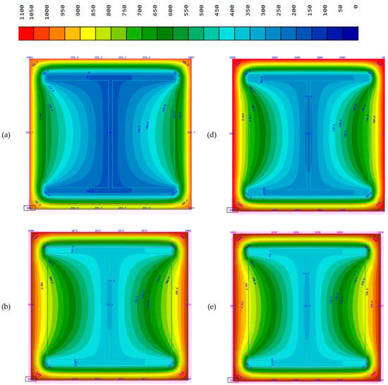
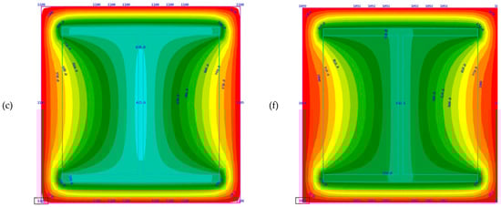
Figure 9.
Temperature distribution through the cross section by the 90th, the 120th, and the 180th min of fire impact in a standard fire case and in a hydrocarbon fire case (standard fire, 90, 120, and 180 min (a–c); hydrocarbon fire, 90, 120, 180 min (d–f)).
Simulating the structures’ performance under various fire modes until reaching the critical temperatures shows a result of 285 min with the standard fire and 290 min with the hydrocarbon fire, subject to maintaining the structural fire protection strength (no cracks or buckling). These values are similar due to the fact that the fire curves mathematically tend to get closer to each other if considerably long time periods are taken (Figure 10).
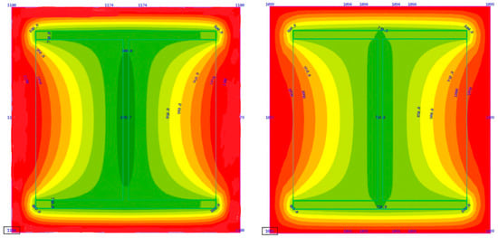
Figure 10.
Simulation outcomes for reaching the I-beam critical temperatures in various fire cases; (left): standard fire curve, 285 min (right): hydrocarbon fire curve, 290 min.
3. Results
Table 5 provides the study results for the steel column fire resistance in the two fire cases.
Table 5.
Results of an experimental study, steel column.
Figure 11 and Figure 12 indicate the temperature curves for heating and vertical deformation of the steel column prototypes clad with fireproof slabs, as well as values obtained through simulation for the two fire cases.
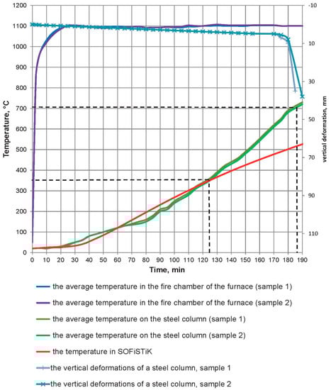
Figure 11.
Temperature curves for the furnace firebox, for the experimental prototypes heating, and SOFiSTiK simulation values for hydrocarbon fire.
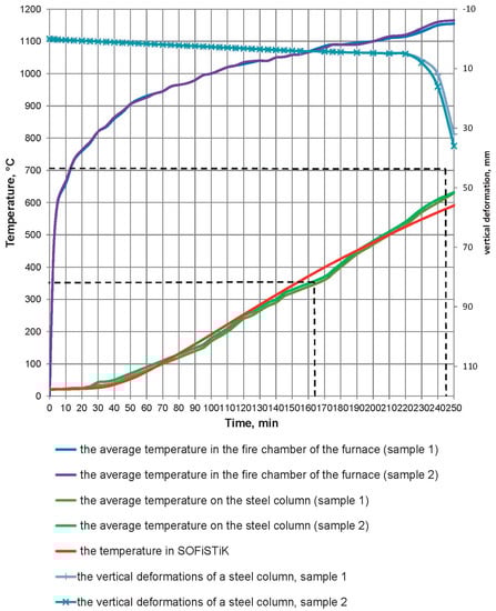
Figure 12.
Temperature curves for the furnace firebox, for the experimental prototypes heating, and simulation values for standard fire.
The difference in the heating temperature of the structures between the experimental and the calculated data for standard fire within any time period are not more than 20%. The middle point of the I-beam web was taken as the benchmark for analyzing the temperature. A critical temperature of 665 °C was reached in the 285th min of the simulation session; consequently, it may be stated that the design fire resistance limit of the structure is R240 for standard fire, and the simulation values are in line with those obtained through the fire tests.
Considering the hydrocarbon fire, design temperature values before the 125th min differ from the test values by not more than 20%. In line with the schedule, the curve slope angle, with regard to the simulation results, is in line with the experimental test curve angle. However, after the 125th min, a dramatic change occurs where the critical temperature of 713 °C is reached during the simulation only in the 290th min of fire impact. The reason for this stark difference is the deformation of fireproof slabs and cracking of the vertical cladding joints that started gradually on the 125th min of the test session (Figure 13 and Figure 14).
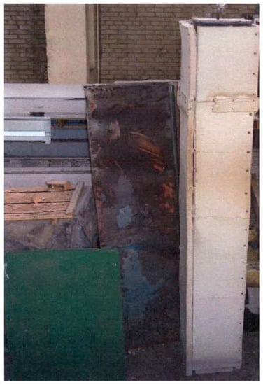
Figure 13.
Engineering prototype after the test, standard fire.
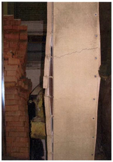
Figure 14.
Vertical deformation of the column engineering prototype, hydrocarbon fire.
The loss of fire protection structural integrity during the heating and the installation accuracy cannot be considered for the simulation purposes, which in the authors’ view accounts for the increased time of reaching the critical temperature using the software (Table 6). The fire resistance limit of this structure with a load of 30 tf can potentially be 290 min; however, to achieve this, the fireproof slab joints need to be additionally elaborated to prevent the opening of the cladding vertical joints.
Table 6.
Comparison between the results of experimental research and the steel column simulation.
4. Conclusions
Fire resistance experimental studies of the steel columns with Pyro-Safe Aestuver T slabs fire protection were performed with standard fire and hydrocarbon fire temperature cases. The critical temperature values were reached in the 240th min (standard fire) and the 180th min (hydrocarbon fire). In the latter case, a progressive deformation of fireproof slabs and cracking of the vertical cladding joints started gradually on the 125th min of the test session.
Not having a possibility to take into consideration the loss of fireproofing structural integrity during the heating or the installation accuracy may entail a discrepancy in the limit state indicators. The SOFiSTiK simulation shows that the fire resistance limit of the structure in hydrocarbon fire is 58% higher (the slabs cracking during the test) than the actual values taken from the fire tests; for a standard fire, the difference is 15%. The fire resistance limit of this structure with a 30 tf loading can potentially be 290 min; however, to achieve this, the fireproof slab joints need to be upgraded to ensure that the cladding vertical joints do not crack open. The thermophysical characteristics of fireproofing materials need to be determined within the temperature range depending on the assumed heating conditions while performing the simulation, in order to obtain the heating profiles that are as close as possible to the actual experimental studies data.
Simulation using the SOFiSTiK software can be used to assess the structural steel heating under different fire condition cases, which will allow for selecting the proper means of fire protection at the relevant design stage of buildings or of oil and gas facilities, including bridges and tunnels.
Author Contributions
Conceptualization, M.G.; Investigation, E.G. and B.K.; Software, I.D. All authors have read and agreed to the published version of the manuscript.
Funding
This research received no external funding.
Data Availability Statement
Testing laboratory of the Federal State Budgetary Institution “All-Russian Order” Badge of Honor “Research Institute of Fire Defense”.
Acknowledgments
The authors are grateful to Prozask LLC in general and personally to Antonov Sergei Porfirevich for both their invaluable contribution to the development of national science in the field of fire safety and the provision of test protocols and materials for experiment.
Conflicts of Interest
The authors declare no conflict of interest.
References
- Gravit, M.; Gumerova, E.; Bardin, A.; Lukinov, V. Increase of Fire Resistance Limits of Building Structures of Oil-and-Gas Complex under Hydrocarbon Fire. In Proceedings of the International Scientific Conference Energy Management of Municipal Transportation Facilities and Transport, EMMFT 2017, Khabarovsk, Russia, 10–13 April 2017; Advances in Intelligent Systems and Computing. Murgul, V., Popovic, Z., Eds.; Springer: Cham, Switzerland, 2018; Volume 692. [Google Scholar] [CrossRef]
- Imran, M.; Liew, M.S.; Nasif, M.S. Experimental Studies on Fire for Offshore Structures and Its Limitations: A Review. Chem. Eng. 2015, 45, 1951–1956. [Google Scholar]
- Awang, M.; Negash, B.M.; Akhir, N.A.; Lubis, L.A.; Rafek, A.G. (Eds.) ICIPEG 2016 (Proceedings of the International Conference on Integrated Petroleum Engineering and Geosciences); Springer Nature Singapore: Singapore, 2017; pp. 801–808. ISBN 978-981-10-3650-7. [Google Scholar]
- Wald, F.; Da Silva, L.S.; Moore, D.B.; Lennon, T.; Chladna, M.; Santiago, A.; Beneš, M.; Borges, L. Experimental Behaviour of a Steel Structure under Natural Fire. Fire Saf. J. 2016, 41, 509–522. [Google Scholar] [CrossRef]
- Eremina, T.; Korolchenko, D. Fire Protection of Building Constructions with the Use of Fire-Retardant Intumescent Compositions. Buildings 2020, 10, 185. [Google Scholar] [CrossRef]
- Zybina, O.; Gravit, M. Intumescent Coatings for Fire Protection of Building Structures and Materials; Springer Series on Polymer and Composite Materials; Springer International Publishing: Cham, Switzerland, 2020; p. 210. ISBN 978-3-030-59422-0. [Google Scholar] [CrossRef]
- EN 1363-2:1999 Fire Resistance Tests. Alternative and Additional Procedures. Available online: https://standards.iteh.ai/catalog/standards/cen/2c26aa21-abe7-4d96-96a2-eb8fbb4919e0/en-1363-2-1999 (accessed on 24 April 2021).
- ISO 834-1:1999, Fire-Resistance Tests—Elements of Building Construction—Part 1: General Requirements. Available online: https://www.iso.org/standard/2576.html (accessed on 24 April 2021).
- Code of Practice. SP122.13330.2012. Railways and Highway Tunnels. Available online: https://docs.cntd.ru/document/1200095544 (accessed on 24 April 2021).
- Gravit, M.; Golub, E.; Antonov, S. Fire protective dry plaster composition for structures in hydrocarbon fire. Mag. Civ. Eng. 2018, 3, 86–94. [Google Scholar] [CrossRef]
- Gravit, M.V.; Golub, E.V.; Grigoriev, D.M.; Ivanov, I.O. Fireproof suspended ceilings with high fire resistance limits. Mag. Civ. Eng. 2018, 84, 75–85. [Google Scholar] [CrossRef]
- Aravindhan, C.; Vasudevan, M.; Arun, M. Numerical modeling on behavior of concrete under elevated temperatures. Int. J. Eng. Adv. Technol. 2018, 8, 110–113. [Google Scholar]
- Kraus, P.; Mensinger, M.; Tabeling, F.; Schaumann, P. Experimental and Numerical Investigations of Steel Profiles with Intumescent Coating Adjacent to Space-Enclosing Elements in Fire. J. Struct. Fire Eng. 2015, 6, 237–246. [Google Scholar] [CrossRef]
- Schaumann, P.; Kirsch, T. Protected Steel and Composite Connections. J. Struct. Fire Eng. 2015, 6, 41–48. [Google Scholar] [CrossRef]
- Zhou, K.; Han, L.-H. Modelling the behaviour of concrete-encased concrete-filled steel tube (CFST) columns subjected to full-range fire. Eng. Struct. 2019, 183, 265–280. [Google Scholar] [CrossRef]
- Simões, Y.S.; Rocha, F.M.; Neto, J.M. Numerical analysis of steel columns subjected to fire. Multidiscip. Model. Mater. Struct. 2019, 15, 387–397. [Google Scholar] [CrossRef]
- Gravit, M.; Zimin, S.; Lazarev, Y.; Dmitriev, I.; Golub, E. Fire Simulation of Bearing Structures for Natural Gas Module Plant. In VIII International Scientific Siberian Transport Forum; Advances in Intelligent Systems and Computing; Popovic, Z., Manakov, A., Breskich, V., Eds.; Springer: Cham, Switzerland, 2020; Volume 1116. [Google Scholar]
- Russian Government Standard GOST R 30247.0-94. Elements of Building Constructions. Fire-Resistance Test Methods. General Requirements. Available online: https://www.russiangost.com/p-17524-gost-302470-94.aspx (accessed on 7 September 2020).
- Russian Government Standard GOST 27772-88 Rolled Products for Structural Steel Constructions. General Specifications. Available online: https://docs.cntd.ru/document/1200003192 (accessed on 24 April 2021).
- Russian Government Standard GOST R 30247.1-94. Elements of Building Constructions. Fire-Resistance Test Methods. Loadbearing and Separating Constructions. Available online: https://www.russiangost.com/p-16532-gost-302471-94.aspx (accessed on 7 September 2020).
- Gravit, M.; Dmitriev, I.; Lazarev, Y. Validation of the Temperature Gradient Simulation in Steel Structures in SOFiSTiK. In Proceedings of the International Scientific Conference Energy Management of Municipal Facilities and Sustainable Energy Technologies EMMFT 2018, Samara, Russia, 10–13 December 2018; Advances in Intelligent Systems and Computing. Murgul, V., Pasetti, M., Eds.; Springer: Cham, Switzerland, 2019; Volume 983. [Google Scholar] [CrossRef]
- Organization Standard ADSC 11251254.001-018-03 Design of Fire Protection of Load-Bearing Steel Structures Using Various Types of Linings; Association for the Development of Steel Construction; Axiom Graphics Union: Moscow, Russia, 2018; ISBN 9785604087855.
- Yakovlev, A.I. Calculation of Fire Resistance of Building Structures; Stroyizdat: Moscow, Russia, 1988; ISBN 5-274-00178-5. [Google Scholar]
Publisher’s Note: MDPI stays neutral with regard to jurisdictional claims in published maps and institutional affiliations. |
© 2021 by the authors. Licensee MDPI, Basel, Switzerland. This article is an open access article distributed under the terms and conditions of the Creative Commons Attribution (CC BY) license (https://creativecommons.org/licenses/by/4.0/).