
The Combined Use of SLAM Laser Scanning and TLS for the 3D Indoor Mapping

 , ,
, ,
Abstract
:1. Introduction
2. Related Studies
2.1. Measurement Methods for the Indoor Environment
2.2. Georeferencing Indoor TLS Point Clouds
2.3. SLAM Laser Scanning of the Indoor Environment
2.4. The Data Integration of TLS and SLAM LSs
3. Materials and Methods
3.1. TLS Registration with SLAM in Large Buildings
3.2. Case Study
3.2.1. Study Site
3.2.2. Reference Data
3.2.3. Test Data
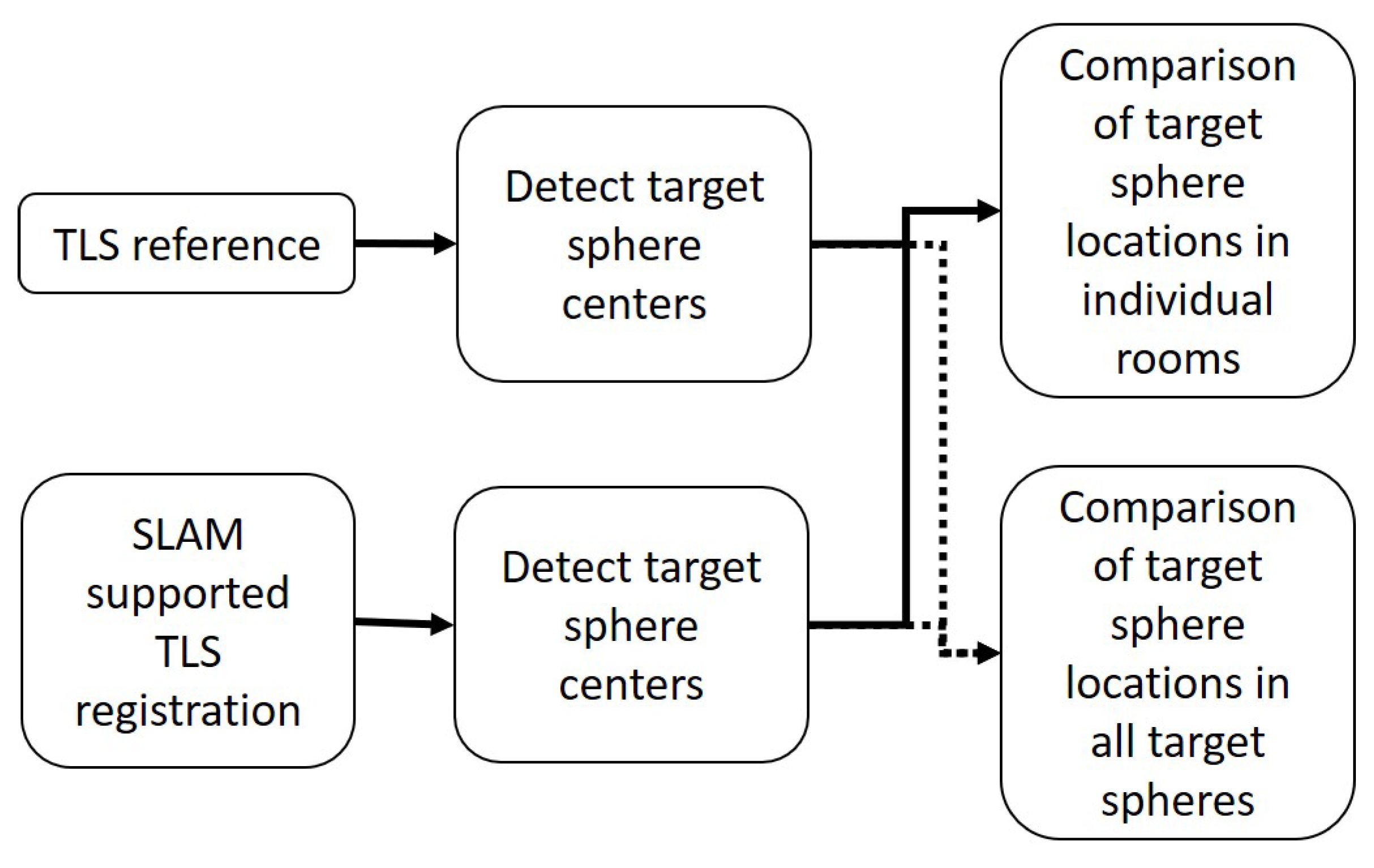
3.2.4. Evaluation Method
4. Results
4.1. Registration
4.2. The Accuracy Assessment of the Room Point Cloud Locations
5. Discussion
6. Conclusions
Author Contributions
Funding
Institutional Review Board Statement
Informed Consent Statement
Conflicts of Interest
References
- Georgopoulos, A.; Stathopoulou, E.K. Data Acquisition for 3D Geometric Recording: State of the Art and Recent Innovations. In Heritage and Archaeology in the Digital Age: Acquisition, Curation, and Dissemination of Spatial Cultural Heritage Data; Vincent, M.L., López-Menchero Bendicho, V.M., Ioannides, M., Levy, T.E., Eds.; Quantitative Methods in the Humanities and Social Sciences; Springer International Publishing: Cham, Switzerland, 2017; pp. 1–26. [Google Scholar] [CrossRef]
- Büyüksalih, G.; Kan, T.; Özkan, G.E.; Meriç, M.; Isın, L.; Kersten, T.P. Preserving the Knowledge of the Past Through Virtual Visits: From 3D Laser Scanning to Virtual Reality Visualisation at the Istanbul Çatalca İnceğiz Caves. PFG J. Photogramm. Remote Sens. Geoinf. Sci. 2020, 88, 133–146. [Google Scholar] [CrossRef]
- Nowak, R.; Orłowicz, R.; Rutkowski, R. Use of TLS (LiDAR) for Building Diagnostics with the Example of a Historic Building in Karlino. Buildings 2020, 10, 24. [Google Scholar] [CrossRef] [Green Version]
- Liu, J.; Xu, D.; Hyyppä, J.; Liang, Y. A Survey of Applications with Combined BIM and 3D Laser Scanning in the Life Cycle of Buildings. IEEE J. Sel. Top. Appl. Earth Obs. Remote Sens. 2021, 14, 5627–5637. [Google Scholar] [CrossRef]
- Hichri, N.; Stefani, C.; Luca, L.; Véron, P. Review Of The “As-built BIM” Approaches. ISPRS Int. Arch. Photogramm. Remote Sens. Spat. Inf. Sci. 2013, XL-5/W1, 107–112. [Google Scholar] [CrossRef] [Green Version]
- Sanhudo, L.; Ramos, N.M.M.; Martins, J.P.; Almeida, R.M.S.F.; Barreira, E.; Simões, M.L.; Cardoso, V. A framework for in-situ geometric data acquisition using laser scanning for BIM modelling. J. Build. Eng. 2020, 28, 101073. [Google Scholar] [CrossRef]
- Pica, D.; Abanda, F. Emerging BIM-3D-Laser Scanning Integration in Construction Practice. In Proceedings of the CITC Global—Construction in the 21st Century, London, UK, 9–11 September 2019. [Google Scholar]
- Díaz-Vilariño, L.; Khoshelham, K.; Martínez-Sánchez, J.; Arias, P. 3D Modeling of Building Indoor Spaces and Closed Doors from Imagery and Point Clouds. Sensors 2015, 15, 3491–3512. [Google Scholar] [CrossRef] [Green Version]
- Jia, F.; Lichti, D.D. A Model-Based Design System for Terrestrial Laser Scanning Networks in Complex Sites. Remote Sens. 2019, 11, 1749. [Google Scholar] [CrossRef] [Green Version]
- Pérez Ramos, A.; Robleda Prieto, G. 3D Virtualization by Close Range Photogrammetry Indoor Gothic Church Apses. The Case Study of Church of San Francisco in Betanzos (la CORUÑA, Spain). ISPRS Int. Arch. Photogramm. Remote Sens. Spat. Inf. Sci. 2015, XL-5/W4, 201–206. [Google Scholar] [CrossRef] [Green Version]
- Hartono, J.R.; Oei, F.J. A Proposal of image-based measurement instead of laser-based measurement for indoor application. IOP Conf. Ser. Mater. Sci. Eng. 2020, 1007, 012026. [Google Scholar] [CrossRef]
- Kalantari, M.; Nechifor, M. Accuracy and utility of the Structure Sensor for collecting 3D indoor information. Geo-Spat. Inf. Sci. 2016, 19, 202–209. [Google Scholar] [CrossRef]
- Pintore, G.; Mura, C.; Ganovelli, F.; Fuentes-Perez, L.; Pajarola, R.; Gobbetti, E. State-of-the-art in Automatic 3D Reconstruction of Structured Indoor Environments. Comput. Graph. Forum 2020, 39, 667–699. [Google Scholar] [CrossRef]
- Maboudi, M.; Bánhidi, D.; Gerke, M. Evaluation of Indoor Mobile Mapping Systems. In Proceedings of the GFaI Workshop 3D North East 2017 (20th Application-oriented Workshop on Measuring, Modeling, Processing and Analysis of 3D-Data), Berlin, Germany, 7–8 December 2017. [Google Scholar]
- Salgues, H.; Macher, H.; Landes, T. Evaluation of Mobile Mapping Systems For Indoor Surveys. Int. Arch. Photogramm. Remote Sens. Spat. Inf. Sci. 2020, 44, 119–125. [Google Scholar] [CrossRef]
- Bassier, M.; Yousefzadeh, M.; Van Genechten, B. Evaluation of Data Acquisition Techniques and Workflows for Scan to BIM; Geo Bussiness: London, UK, 2015. [Google Scholar]
- Kersten, T.P.; Mechelke, K.; Lindstaedt, M.; Sternberg, H. Methods for Geometric Accuracy Investigations of Terrestrial Laser Scanning Systems. Photogramm. Fernerkund. Geoinf. 2009, 2009, 301–315. [Google Scholar] [CrossRef]
- Ingman, M.; Virtanen, J.P.; Vaaja, M.T.; Hyyppä, H. A Comparison of Low-Cost Sensor Systems in Automatic Cloud-Based Indoor 3D Modeling. Remote Sens. 2020, 12, 2624. [Google Scholar] [CrossRef]
- Cantoni, S.; Vassena, G. Fast Indoor Mapping To Feed An Indoor Db For Building And Facility Management. In Proceedings of the 8th International Workshop 3D-ARCH “3D Virtual Reconstruction and Visualization of Complex Architectures” on International Archives of the Photogrammetry, Remote Sensing and Spatial Information Sciences, Bergamo, Italy, 6–8 February 2019; Volume XLII-2-W9, pp. 213–217. [Google Scholar] [CrossRef] [Green Version]
- Hullo, J.F.; Grussenmeyer, P.; Landes, T.; Thibault, G. Georeferencing Of Tls Data For Industrial Indoor Complex Scenes: Beyond Current Solutions. In Proceedings of the ISPRS Calgary 2011 Workshop on International Archives of the Photogrammetry, Remote Sensing and Spatial Information Sciences, Calgary, Canada, 29–31 August 2011; Volume XXXVIII-5-W12, pp. 185–190. [Google Scholar] [CrossRef] [Green Version]
- Soudarissanane, S.; Lindenbergh, R. Optimizing terrestrial laser scanning measurement set-up. ISPRS Int. Arch. Photogramm. Remote Sens. Spat. Inf. Sci. 2012, XXXVIII-5/W12. [Google Scholar] [CrossRef] [Green Version]
- Tucci, G.; Visintini, D.; Bonora, V.; Parisi, E.I. Examination of Indoor Mobile Mapping Systems in a Diversified Internal/External Test Field. Appl. Sci. 2018, 8, 401. [Google Scholar] [CrossRef] [Green Version]
- Tang, J.; Wen, J.; Qian, C. A Distributed Indoor Mapping Method Based on Control-Network-Aided SLAM: Scheme and Analysis. Appl. Sci. 2020, 10, 2420. [Google Scholar] [CrossRef] [Green Version]
- Sirmacek, B.; Shen, Y.; Lindenbergh, R.; Zlatanova, S.; Diakite, A. Comparison Of Zeb1 And Leica C10 Indoor Laser Scanning Point Clouds. ISPRS Ann. Photogramm. Remote Sens. Spatial Inf. Sci. 2016, III-1, 143–149. [Google Scholar] [CrossRef] [Green Version]
- Chiabrando, F.; Della Coletta, C.; Sammartano, G.; Spanò, A.; Spreafico, A. “Torino 1911” Project: A Contribution Of A SLAM-based Survey To Extensive 3D Heritage Modeling. Int. Arch. Photogramm. Remote Sens. Spat. Inf. Sci. 2018, XLII-2, 225–234. [Google Scholar] [CrossRef] [Green Version]
- Di Filippo, A.; Sánchez-Aparicio, L.J.; Barba, S.; Martín-Jiménez, J.A.; Mora, R.; González Aguilera, D. Use of a Wearable Mobile Laser System in Seamless Indoor 3D Mapping of a Complex Historical Site. Remote Sens. 2018, 10, 1897. [Google Scholar] [CrossRef] [Green Version]
- Chen, Y.; Tang, J.; Jiang, C.; Zhu, L.; Lehtomäki, M.; Kaartinen, H.; Kaijaluoto, R.; Wang, Y.; Hyyppä, J.; Hyyppä, H.; et al. The Accuracy Comparison of Three Simultaneous Localization and Mapping (SLAM)-Based Indoor Mapping Technologies. Sensors 2018, 18, 3228. [Google Scholar] [CrossRef] [Green Version]
- Lehtola, V.V.; Kaartinen, H.; Nüchter, A.; Kaijaluoto, R.; Kukko, A.; Litkey, P.; Honkavaara, E.; Rosnell, T.; Vaaja, M.T.; Virtanen, J.P.; et al. Comparison of the Selected State-Of-The-Art 3D Indoor Scanning and Point Cloud Generation Methods. Remote Sens. 2017, 9, 796. [Google Scholar] [CrossRef] [Green Version]
- Sepasgozar, S.M.E.; Davis, S. Construction Technology Adoption Cube: An Investigation on Process, Factors, Barriers, Drivers and Decision Makers Using NVivo and AHP Analysis. Buildings 2018, 8, 74. [Google Scholar] [CrossRef] [Green Version]
- Allmon, E.; Haas, C.T.; Borcherding, J.D.; Goodrum, P.M. U.S. Construction Labor Productivity Trends, 1970–1998. J. Constr. Eng. Manag. 2000, 126, 97–104. [Google Scholar] [CrossRef]
- Lu, C.X.; Rosa, S.; Zhao, P.; Wang, B.; Chen, C.; Stankovic, J.A.; Trigoni, N.; Markham, A. See Through Smoke: Robust Indoor Mapping with Low-cost mmWave Radar. arXiv 2020, arXiv:1911.00398. [Google Scholar]
- Chalhoub, J.; Ayer, S.K.; McCord, K.H. Augmented Reality to Enable Users to Identify Deviations for Model Reconciliation. Buildings 2021, 11, 77. [Google Scholar] [CrossRef]
- Mahami, H.; Nasirzadeh, F.; Hosseininaveh Ahmadabadian, A.; Nahavandi, S. Automated Progress Controlling and Monitoring Using Daily Site Images and Building Information Modelling. Buildings 2019, 9, 70. [Google Scholar] [CrossRef] [Green Version]
- Masiero, A.; Fissore, F.; Guarnieri, A.; Pirotti, F.; Visintini, D.; Vettore, A. Performance Evaluation of Two Indoor Mapping Systems: Low-Cost UWB-Aided Photogrammetry and Backpack Laser Scanning. Appl. Sci. 2018, 8, 416. [Google Scholar] [CrossRef] [Green Version]
- Wang, M.; Wang, C.C.; Sepasgozar, S.; Zlatanova, S. A Systematic Review of Digital Technology Adoption in Off-Site Construction: Current Status and Future Direction towards Industry 4.0. Buildings 2020, 10, 204. [Google Scholar] [CrossRef]
- Abdul Shukor, S.; Wong, R.; Rushforth, E.; Basah, S.; Zakaria, A. 3D terrestrial laser scanner for managing existing building. J. Teknol. 2015, 76. [Google Scholar] [CrossRef] [Green Version]
- Otero, R.; Lagüela, S.; Garrido, I.; Arias, P. Mobile indoor mapping technologies: A review. Autom. Constr. 2020, 120, 103399. [Google Scholar] [CrossRef]
- Schuhmacher, S.; Böhm, J. Georeferencing of Terrestrial Laserscanner Data for Applications in Architectural Modeling. 2005. Available online: https://elib.uni-stuttgart.de/bitstream/11682/3766/1/schuhmacher05_venedig.pdf (accessed on 27 August 2007).
- Nocerino, E.; Menna, F.; Remondino, F.; Toschi, I.; Rodríguez-Gonzálvez, P. Investigation of Indoor and Outdoor Performance of Two Portable Mobile Mapping Systems; 2017. Available online: https://www.spiedigitallibrary.org/conference-proceedings-of-spie/10332/103320I/Investigation-of-indoor-and-outdoor-performance-of-two-portable-mobile/10.1117/12.2270761.short?SSO=1 (accessed on 26 August 2021).
- Zlot, R.; Bosse, M.; Greenop, K.; Jarzab, Z.; Juckes, E.; Roberts, J. Efficiently capturing large, complex cultural heritage sites with a handheld mobile 3D laser mapping system. J. Cult. Herit. 2014, 15, 670–678. [Google Scholar] [CrossRef]
- Sepasgozar, S.M.E.; Lim, S.; Shirowzhan, S.; Kim, Y.M. Implementation of As-Built Information Modelling Using Mobile and Terrestrial Lidar Systems. In Proceedings of the International Symposium on Automation and Robotics in Construction; IAARC Publications: Waterloo, ON, Canada, 2014; Volume 31, pp. 1–8. [Google Scholar]
- Thomson, C.; Apostolopoulos, G.; Backes, D.; Boehm, J. Mobile Laser Scanning for Indoor Modelling. ISPRS Ann. Photogramm. Remote Sens. Spat. Inf. Sci. 2013, II-5-W2, 289–293. [Google Scholar] [CrossRef] [Green Version]
- Samad, A.; Omar, M.; Sahriman, N.; Johan, J.; Ahmat Ruslan, F.; Adnan, R. Implementation of Zebedee 3D Laser Scanner Sensor for Preparation of Strata Title Plan. In Proceedings of the 7th IEEE Control and System Graduate Research Colloquium (ICSGRC), Shah Alam, Malaysia, 8 August 2016; pp. 209–214. [Google Scholar] [CrossRef]
- Russhakim, N.a.S.; Ariff, M.F.M.; Majid, Z.; Idris, K.M.; Darwin, N.; Abbas, M.A.; Zainuddin, K.; Yusoff, A.R. The Suitability of Terrestrial Laser Scanning For Building Survey And Mapping Applications. Int. Arch. Photogramm. Remote Sens. Spat. Inf. Sci. 2019, XLII-2-W9, 663–670. [Google Scholar] [CrossRef] [Green Version]
- Nikoohemat, S.; Koeva, M.; Oude Elberink, S.J.; Lemmen, C.H.J. Change Detection From Point Clouds To Support Indoor 3d Cadastre. Int. Arch. Photogramm. Remote Sens. Spat. Inf. Sci. 2018, XLII-4, 451–457. [Google Scholar] [CrossRef] [Green Version]
- Micoli, L.; Barsanti, S.G.; Malik, U.; Guidi, G. 3D data integration for the digital reconstruction of cultural heritage monuments. IOP Conf. Ser. Mater. Sci. Eng. 2018, 364, 012043. [Google Scholar] [CrossRef]
- Altuntas, C.; Yildiz, F.; Scaioni, M. Laser Scanning and Data Integration for Three-Dimensional Digital Recording of Complex Historical Structures: The Case of Mevlana Museum. ISPRS Int. J. Geo-Inf. 2016, 5, 18. [Google Scholar] [CrossRef] [Green Version]
- Wen, C.; Sun, X.; Hou, S.; Tan, J.; Dai, Y.; Wang, C.; Li, J. Line Structure-Based Indoor and Outdoor Integration Using Backpacked and TLS Point Cloud Data. IEEE Geosci. Remote Sens. Lett. 2018, 15, 1790–1794. [Google Scholar] [CrossRef]
- Serrano, D.; Haag, M.; Dill, E.; Vilardaga, S.; Duan, P. Seamless Indoor-Outdoor Navigation for Unmanned Multi-Sensor Aerial Platforms. Int. Arch. Photogramm. Remote Sens. Spat. Inf. Sci. 2014, 40. [Google Scholar] [CrossRef] [Green Version]
- Ellul, C.; Boyes, G.; Thomson, C.; Backes, D. Towards Integrating BIM and GIS—An End-to-End Example from Point Cloud to Analysis. In Lecture Notes in Geoinformation and Cartography; 2017; pp. 495–512. Available online: https://link.springer.com/chapter/10.1007%2F978-3-319-25691-7_28 (accessed on 26 August 2021).
- Sammartano, G.; Spanò, A. Point clouds by SLAM-based mobile mapping systems: Accuracy and geometric content validation in multisensor survey and stand-alone acquisition. Appl. Geomat. 2018, 10, 317–339. [Google Scholar] [CrossRef]
- Chiabrando, F.; Sammartano, G.; Spanò, A.; Spreafico, A. Hybrid 3D Models: When Geomatics Innovations Meet Extensive Built Heritage Complexes. ISPRS Int. J. Geo-Inf. 2019, 8, 124. [Google Scholar] [CrossRef] [Green Version]
- Vanneschi, C.; Eyre, M.; Francioni, M.; Coggan, J. The Use of Remote Sensing Techniques for Monitoring and Characterization of Slope Instability. Procedia Eng. 2017, 191, 150. [Google Scholar] [CrossRef] [Green Version]
- Otakaari 4. Available online: Https://www.aalto.fi/en/locations/otakaari-4 (accessed on 23 June 2021).
- ZEB Horizon: SLAM LiDAR for 3D Mapping with Drones. Available online: Https://geoslam.com/solutions/zeb-horizon/ (accessed on 23 June 2021).
- Bosse, M.; Zlot, R.; Flick, P. Zebedee: Design of a Spring-Mounted 3-D Range Sensor with Application to Mobile Mapping. IEEE Trans. Robot. 2012, 28, 1104–1119. [Google Scholar] [CrossRef]
- Frangez, V.; Kramis, B.; Hübscher, F.; Baumann, A. Comparison of Three Innovative Technologies for 3D-Acquisition, Modelling, and Visualization of an Underground Mine. In Proceedings of the International Federation of Surveyors (FIG) Congress 2018, Istanbul, Turkey, 6–11 May 2018. [Google Scholar]
- Cabo, C.; Del Pozo, S.; Rodríguez-Gonzálvez, P.; Ordóñez, C.; González-Aguilera, D. Comparing Terrestrial Laser Scanning (TLS) and Wearable Laser Scanning (WLS) for Individual Tree Modeling at Plot Level. Remote Sens. 2018, 10, 540. [Google Scholar] [CrossRef] [Green Version]
- Hyyppä, E.; Hyyppä, J.; Hakala, T.; Kukko, A.; Wulder, M.A.; White, J.C.; Pyörälä, J.; Yu, X.; Wang, Y.; Virtanen, J.P.; et al. Under-canopy UAV laser scanning for accurate forest field measurements. ISPRS J. Photogramm. Remote Sens. 2020, 164, 41–60. [Google Scholar] [CrossRef]
- Zlot, R.; Bosse, M. Three-Dimensional Mobile Mapping of Caves. J. Cave Karst Stud. 2014, 76, 191–206. [Google Scholar] [CrossRef]
- Dewez, T.J.B.; Yart, S.; Thuon, Y.; Pannet, P.; Plat, E. Towards cavity-collapse hazard maps with Zeb-Revo handheld laser scanner point clouds. Photogramm. Rec. 2017, 32, 354–376. [Google Scholar] [CrossRef] [Green Version]


| Author | Sensors | Study Site |
|---|---|---|
| Maboudi et al. [14] | A Viametris iMS3D and a GeoSLAM Zeb-reve | Three rooms on the same floor of a modern building |
| Lehtola et al. [28] | A Matterport, NavVis M3, GeoSLAM Zeb1, Kaarta Stencil, Leica Pegasus, Aalto VILMA, FGI SLAMMER and a Würzburg backpack | A hall, a two-story garage, and a big open space/room |
| Sirmacek et al. [24] | A GeoSLAM Zeb1 | A fire station |
| Nocerino et al. [39] | A GeoSLAM Zeb-revo and a Leica Pegasus Backpack | A two-floor building and an open city square |
| Salgues et al. [15] | A GeoSLAM Zeb-revo RT and a GreenValley LiBackpack C50 | A tower, museum, and a huge laboratory |
| Chen et al. [27] | A Matterport 3D camera, FGI SLAMMER, and an FGI NAVIS | An L-shaped corridor and an open style library |
| Tucci et al. [22] | A Kaarta Stencil, Leica Pegasus Backpack, and a GeoSLAM Zeb-revo | An old fortress |
| Chiabrando et al. [25] | A GeoSLAM Zeb-revo RT | A cultural heritage castle and a village |
| Di Filippo et al. [26] | A GeoSLAM Zeb-revo | A gothic palace in ruins |
| Micoli et al. [46] | A GeoSLAM Zeb-revo | A late Roman circus in Milan |
| Zlot et al. [40] | A GeoSLAM Zeb1 | A large outdoor cultural heritage site, Peel Island |
| Sepasgozar et al. [41] | A GeoSLAM Zeb1 | A campus building |
| Thomson et al. [42] | A Viametris i-MMS and GeoSLAM Zeb1 | The ground floor of a campus building |
| Tang et al. [23] | A self-built SLAM LS system | A large indoor parking lot |
| Samad et al. [43] | A GeoSLAM Zeb1 | A hostel building |
| Russhakim et al. [44] | A GeoSLAM Zeb-revo | One floor of a campus building |
| Nikoohemat et al. [45] | A GeoSLAM Zeb-revo and a backpack system | One floor of a modern building |
| Room 1 | Room 2 | Room 3 | Room 4 | |
|---|---|---|---|---|
| The radius of the target sphere (mm) | 90 | 90 | 60 | 60 |
| The number of the scans in the room | 4 | 9 | 3 | 2 |
| The mean point error (mm) | 3 | 4 | 2 | 1 |
| The maximum point error (mm) | 15 | 15 | 15 | 15 |
| Overlap (%) | 76 | 62 | 74 | 81 |
| SLAMCover | SLAMBrief | SLAMCover | SLAMBrief | SLAMCover | SLAMBrief | |
|---|---|---|---|---|---|---|
| Time (s) | Trajectory Length (m) | Number of Points (pcs) | ||||
| Room 1 | 38 | 21 | 28.17 | 16.64 | 5717.508 | 2791.663 |
| Room 2 | 112 | 20 | 91.72 | 14.90 | 14,768.751 | 2950.110 |
| Room 3 | 27 | 10 | 16.04 | 6.07 | 3301.177 | 1369.951 |
| Room 4 | 21 | 7 | 13.36 | 5.19 | 3521.344 | 1570.171 |
| The Path Name | The Error | SLAM to TLS Reference |
|---|---|---|
| SLAMCover | The errors of individual Target Spheres outside the building (mm) | 11.91 |
| 15.76 | ||
| 13.99 | ||
| 17.69 | ||
| Combined RMSE of all outside Target Spheres (mm) | 14.84 | |
| SLAMBrief | The errors of individual Target Spheres outside the building (mm) | 16.45 |
| 7.52 | ||
| 10.37 | ||
| 11.83 | ||
| Combined RMSE of all outside Target Spheres (mm) | 11.99 |
| The Path Name | The Error | TLS Room 1 to SLAM | TLS Room 2 to SLAM | TLS Room 3 to SLAM | TLS Room 4 to SLAM |
|---|---|---|---|---|---|
| SLAMCover | The errors of individual Target Spheres in a room (mm) | 6.92 | 8.41 | 9.38 | 8.19 |
| 6.74 | 9.21 | 5.03 | 8.50 | ||
| 7.18 | 9.62 | 8.06 | 9.60 | ||
| 8.37 | |||||
| Combined RMSE of all room Target Spheres (mm) | 7.03 | 8.86 | 7.31 | 8.85 | |
| SLAMBrief | The errors of individual Target Spheres in a room (mm) | 6.69 | 11.67 | 22.82 | 16.06 |
| 2.79 | 13.62 | 13.07 | 18.69 | ||
| 5.00 | 23.00 | 28.49 | 9.75 | ||
| 8.45 | 18.82 | ||||
| Combined RMSE of all room Target Spheres (mm) | 5.08 | 16.84 | 19.84 | 16.07 |
| The Path Name | Space | Mean of the 3D Distance of Target Spheres (mm) |
|---|---|---|
| SLAMCover | Room 1 | 31.67 |
| Room 2 | 37.11 | |
| Room 3 | 49.87 | |
| Room 4 | 42.60 | |
| All rooms | 39.96 | |
| SLAMBrief | Room 1 | 41.54 |
| Room 2 | 51.20 | |
| Room 3 | 20.66 | |
| Room 4 | 18.25 | |
| All rooms | 34.94 |
Publisher’s Note: MDPI stays neutral with regard to jurisdictional claims in published maps and institutional affiliations. |
© 2021 by the authors. Licensee MDPI, Basel, Switzerland. This article is an open access article distributed under the terms and conditions of the Creative Commons Attribution (CC BY) license (https://creativecommons.org/licenses/by/4.0/).
Share and Cite
Keitaanniemi, A.; Virtanen, J.-P.; Rönnholm, P.; Kukko, A.; Rantanen, T.; Vaaja, M.T. The Combined Use of SLAM Laser Scanning and TLS for the 3D Indoor Mapping. Buildings 2021, 11, 386. https://doi.org/10.3390/buildings11090386
Keitaanniemi A, Virtanen J-P, Rönnholm P, Kukko A, Rantanen T, Vaaja MT. The Combined Use of SLAM Laser Scanning and TLS for the 3D Indoor Mapping. Buildings. 2021; 11(9):386. https://doi.org/10.3390/buildings11090386
Chicago/Turabian StyleKeitaanniemi, Aino, Juho-Pekka Virtanen, Petri Rönnholm, Antero Kukko, Toni Rantanen, and Matti T. Vaaja. 2021. "The Combined Use of SLAM Laser Scanning and TLS for the 3D Indoor Mapping" Buildings 11, no. 9: 386. https://doi.org/10.3390/buildings11090386
APA StyleKeitaanniemi, A., Virtanen, J.-P., Rönnholm, P., Kukko, A., Rantanen, T., & Vaaja, M. T. (2021). The Combined Use of SLAM Laser Scanning and TLS for the 3D Indoor Mapping. Buildings, 11(9), 386. https://doi.org/10.3390/buildings11090386