Article

Method for Designing Prequalified Connections Using Generative Design

by
Daniela Henríquez
,
Rodrigo F. Herrera
and
Juan Carlos Vielma
*
Civil Engineering School, Pontificia Universidad Católica de Valparaíso, Valparaíso 2340000, Chile
*
Author to whom correspondence should be addressed.
Buildings 2022, 12(10), 1579; https://doi.org/10.3390/buildings12101579
Submission received: 18 August 2022 / Revised: 23 September 2022 / Accepted: 26 September 2022 / Published: 30 September 2022
(This article belongs to the Special Issue Development of Connections in Steel Structures for Construction)

Abstract

:
Designing prequalified connections is a process of iterative calculation, in which certain dimensions are varied until the verifications and restrictions stipulated by the standard are met. This is a slow process that can be automated using various software and optimized using a new design method called generative design, which consists of establishing restrictions so that the script delivers multiple solutions that meet the objectives. This research was conducted based on the design science research (DSR) methodology and focused on developing a method to design moment-resisting steel connections, specifically end-plate connections, using generative design in a building information modeling (BIM) environment. From this, it was possible to obtain several end-plate connection design alternatives, and technical validation was carried out to verify the functionality of the program using a verification method proposed by a civil engineer.

1. Introduction

The earthquake in Northridge in the city of Los Angeles in 1994 resulted in many failures in the connections of steel structures designed as moment-resisting frames, specifically in beam–column connections [1,2,3]. For this reason, a new type of joint emerged to minimize the damage that an earthquake can cause, called a prequalified connection, which allows a failure that occurs in the connection to be displaced toward the beam that makes up the frame [4,5,6]. There are different types of prequalified connections, such as the reduced beam section, bolted end plate, bolted flange plate, welded flange without reinforcement, and welded web [7], which are explained in the “Prequalified Connections for Special and Intermediate Steel Moment Frames for Seismic Applications” (AISC358), where all the design specifications of each connection can also be found.
Designing prequalified connections is a process of iterative calculation and detailed analysis of each element [8], in which the parameters are varied until a design that complies with the regulations is obtained. This is a set of procedures that, when performed manually, becomes tedious and complex [9]: much time is invested, which can cause delays in delivering the results. Therefore, it is necessary to automate the process to facilitate the calculations and obtain solutions in less time, more simply, and without requiring more effort, allowing problems to be solved safely and yielding a design without errors [4,10]. In this way, the work is simplified; therefore, the time, cost, and human resources that were previously used to carry out manual design can be invested in other organization activities. In addition, this allows the generation of correct designs from an early stage of the project, thus preventing changes in projects that are in advanced development, which could generate higher costs [11,12,13].
The automation of the design of these connections is currently achieved based on traditional methods such as spreadsheets, which only allow verification of whether the proposed design complies with the regulations [14]. Although there is software that automates the design process with preconfigured parametric connections [15,16,17], allowing fast design and analysis, this software has expensive licenses, and the work it performs is individual. That is, such software allows only one design to be verified at a time.
To address these issues, a new form of design called generative design has arisen. This is a method that has made important advances in architecture [18,19], but not as many in structural engineering [20,21,22,23,24,25], since to date there is less experience with using generative design in this field. This process consists of creating models by entering parameters, constraints, and design objectives, from which a wide variety of solutions that meet the desired requirements are automatically obtained [26,27] and from which the most convenient one can be chosen, guaranteeing that the delivered design complies with regulatory requirements. Recently, generative design has been used for steel-structure connection design with different levels of success [28,29].
Another difficulty that arises when a new design is made is that new documentation must be generated that includes the new data and results, and then these updated records must be sent to the interested parties [11]. The information involved may not affect all project professionals, and the best solution for this problem is building information modeling (BIM), which is a project-management methodology that allows collaborative work in real time throughout the entire life cycle of the project [30,31]. This way of working is a new paradigm in projects for the architecture, engineering, and construction (AEC) industry, since all the project information is integrated into the same detailed virtual model [6], to which all the project stakeholders have access. This results in better communication between the parties, more efficient results, and transparent decision-making [32]. In addition, it allows the automation of programming processes, analysis, documentation, coordination of specialties and creation of parametric elements; that is, its geometry, cost, material, and characteristics can be combined [9]. Therefore, modifications, analyses and verifications of a new design do not have to be carried out from scratch, but when parameters are changed, the new documentation is generated automatically, and the different stakeholders of the project are informed accordingly. It should be noted that this methodology can be applied through various software that exists in the market, including different tools for making virtual models [33].
In summary, the prequalified connection designs that are made today are only based on complying with standards and do not ensure that the final design chosen is the optimal and most convenient one. Additionally, the solutions generated are not as attractive, active, or varied because they do not go beyond what a designer could create [26,27]. Given these problems, the aim is to develop a method of designing prequalified connections that is freely accessible and easy to use with software that allows the option of working with generative design to automate the process and thus obtain a wide variety of alternatives as well as design solutions that are innovative and creative.

2. Background

2.1. Prequalified Connections

Prequalified connections originated after the Northridge earthquake of 1994, when it became evident that most of the steel structures designed as frames had suffered damage to their connections, which meant economic losses associated with the repair of the structures [1]. After this event, different studies and investigations were carried out, and it was concluded that the failures in the buildings were mostly due to their design under the regulations in force at that time [34]. So that this type of failure and damage would not occur again in future seismic events, the American Institute of Steel Construction (AISC) and the American National Standards Institute (ANSI) developed a standard that required the use of prequalified connections in moment-resisting steel frame-type structures [34].
Prequalified connections are based on a union of elements with a particular geometric configuration, and they are designed so that when a seismic event occurs, the failure in the connection of the structural system occurs in the frame beam and never in the connection itself. This is known as a strong column–weak beam connection, since it is designed in such a way that the joints and the column are stronger than the beam, thus inducing failure in the weak element, also called a fusible element, and guaranteeing that the union of the elements is not damaged, nor is the integrity of the structure [2].
The design of this type of connection is based on the AISC358-20 standard Prequalified Connections for Special and Intermediate Steel Moment Frames for Seismic Applications, which serves as a practical guide in the application of these connections. The design methodology, parameters, requirements, and details of each member of the connection, field in which they are applied, manufacturing, characteristics of the welds and bolts, prequalification limits, material specifications, etc., are given. These prequalified connections comply with the provisions of the AISC standard Seismic Provisions for Structural Steel Buildings for use in special (SMF) or intermediate (IMF) capacity moment-resisting steel frames [7], which are distinguished according to the type and magnitude of seismic demand that is considered in the design [34].
Prequalified connections may vary in their joining elements, the presence of plates, their position, the type of welding, and the number and position of bolts, among other factors. There is no single design that works, and the results of effective connections that can be obtained to join a column and a beam are varied. They must only comply with what is stipulated in the standard, which is why the design process becomes important and different solutions are obtained at the same time.

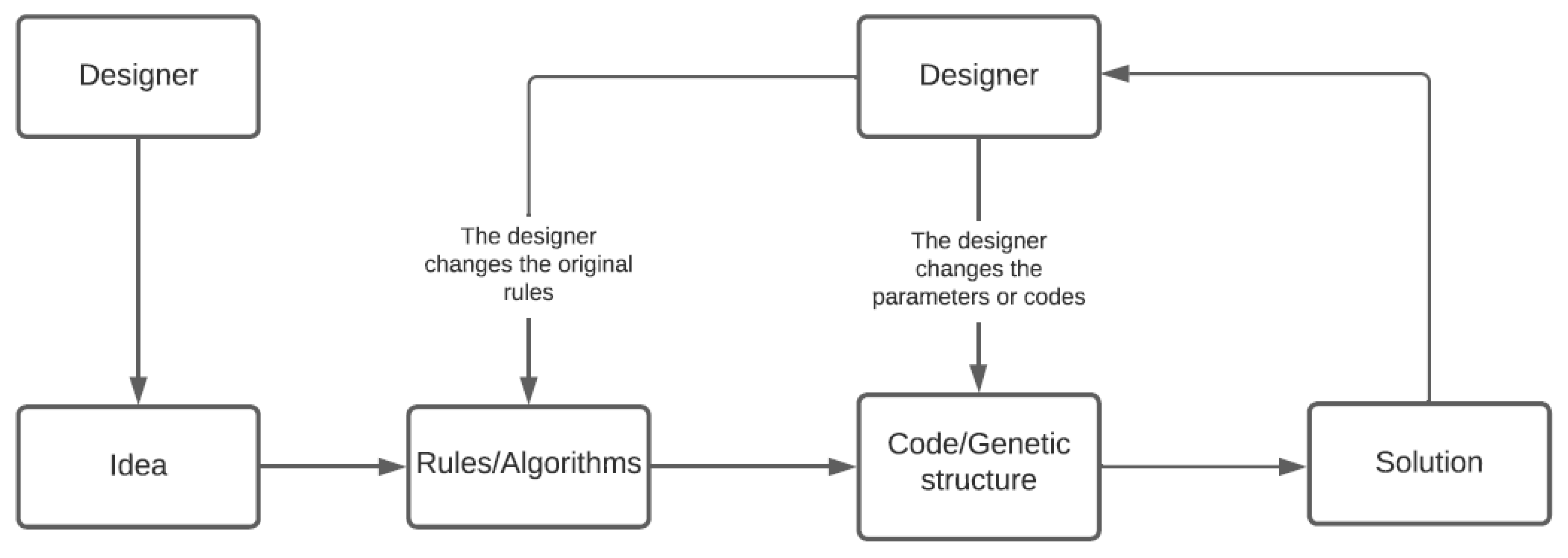
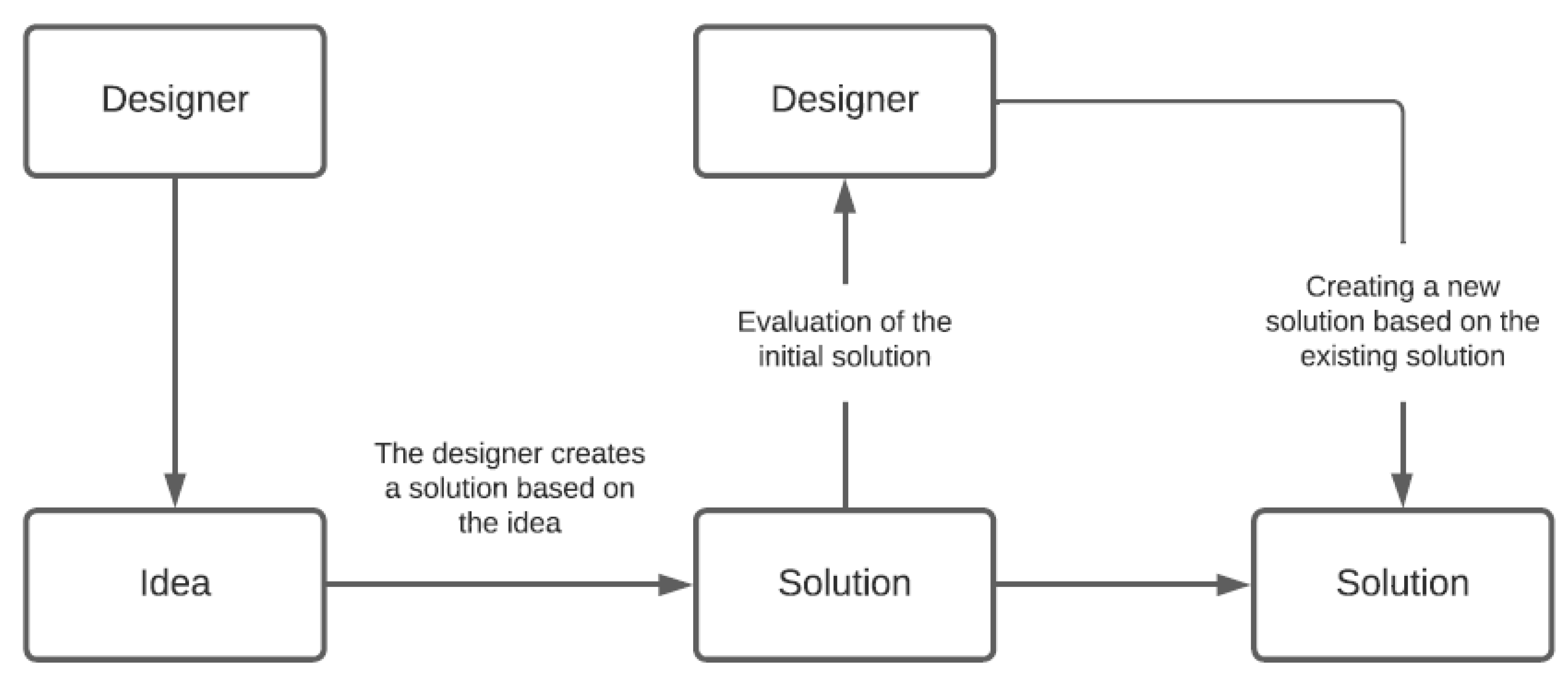
2.2. Comparison between Generative Design and Traditional Design

Generative design is a new form of design that is currently being used that unites parametric design and computational technology without neglecting the designer’s data and criteria. The term “parametric design” is applied in a generic way to the procedures used using BIM, where the different components of the connection are treated as parameters that can be modified in the different steps of the design process. Generative design consists of defining spatial restrictions, materials to be used, and geometric limitations, among other parameters [18], so that through systems structured by algorithms [35], multiple solutions and optimized design options can be obtained automatically that meet the objectives and rules defined at the beginning [18]. These parameters are easily modifiable, so that by altering any rule, there is an immediate change in the delivered design solutions without needing to return to the beginning. This process generates more attractive designs than a designer could have achieved using the traditional design form [36].
There are various definitions of generative design used by different designers and architects according to their points of view, but one designer who makes the objective of this concept clear is Lars Hesselgren, who says that generative design does not solely concern designing a building, but designing a system that conforms to the building [35]. The use of this type of design covers various areas, such as art, music, literature, fashion, generative logos, engineering, and architecture, which is the area in which the AEC industry has developed the most [35].
Generative design aims to create different models that meet the previously established design objectives and, at the same time, meet the restrictions and conditions defined by the user, automatically optimizing the multiple design options provided [36]. The goal is to represent the idea of the designer through rules or algorithms, from which a method or script will be created, resulting in a solution [35]. This obtained solution can be easily modified, either by changing the rules or algorithms or the script without going back to the beginning, as presented in Figure 1.
The classic or traditional form of design is based on creating different design options, where through parametric design, the different desired variables can be modified according to the established objectives and then evaluated. This design process begins with an idea, from which a solution is sought. The designer evaluates this solution and determines whether it meets the criteria. If it does not meet expectations, it is modified and a new solution is created, which is evaluated again until the result meets the expectations [35], as seen in Figure 2.
Both processes presented are iterative, so it is necessary to automate this process in addition to achieving solutions that are optimal, both in cost and quality. There are different tools and technologies to support designers.

2.3. BIM in Process Automation

One of the most complete tools for these cases is the BIM methodology, which allows not only the optimization of resources in projects and the automation of programming processes but also the integration of processes and information in the same detailed virtual model [11]. This new way of working in the AEC industry allows all the information that is handled in a project to be managed in such a way that all parties have access to it, which implies better communication, collaborative work and efficient results throughout the project life cycle [11].
Integrating BIM into metal structure projects allows designers to develop them in a coordinated manner and in less time because, as mentioned above, this methodology allows the parametric design of the elements, i.e., the structural model will include families of profiles [37], from which it will be possible to design the different connections that are necessary and suitable for the structure. Here, the term “families of profiles” refers to the group of profiles that possess common cross-sectional characteristics and that are grouped into catalogues based on this criterion. In addition, the analysis of the structure will be much faster due to the software that allows reliable calculation of the created designs and greater precision in the design. The interoperability between software programs allows the model to be synchronized between them and allows objects, data and connections to be transferred, as the programs are compatible with each other. Additionally, it saves time to have the documentation processes and automated details, generated reports and plans, among others, update automatically when the parameters are changed [37].
Although this methodology is convenient and ideal for the connection design process, it has not been fully implemented in the industry, and there are still many engineers who continue to use a more traditional method without including software that contributes to generating their designs [38].

2.4. Traditional Methods and Software That Allow the Design of Prequalified Connections

As already indicated, the design of prequalified connections requires an iterative process until all regulatory requirements (AISC 360, AISC 341, and AISC 358) are satisfied. This must be repeated if the assigned data do not comply with the rules (AISC 360, AISC 341, and AISC 358), i.e., in the end, the process is about analyzing a series of verifications and ensuring that they operate according to what is stipulated in the regulations [38]. Because this process is repetitive, various tools have been created to help make it less tedious and time-consuming, such as spreadsheets and script, which are programmed according to the standard and allow verification to be done more quickly [1].
On the other hand, there are several pieces of software on the market from different companies that incorporate the connection design process in an automated way. By means of previously configured connections, they allow data to be entered, and the program automatically delivers the analysis of the connection with the entered parameters, ensuring the functionality and quality of the design, but not ensuring that the best solution is obtained in terms of resource optimization [38]. In addition, a disadvantage of this type of software is that its license is expensive, which makes it difficult to obtain, and the time needed to learn how to use it is usually long.
Below, Table 1 presents various pieces of software that include tools to develop connection designs in steel. For each, the name is specified, as well as whether the generative design condition applies and whether it is developed in a BIM environment. A brief description of its operation is also given.
In this table, the different technological tools with which one can work in generative design or that provide a perspective on the BIM methodology are given.
There are several prequalified connections that are specified in the standard, not all of which are used, since several are difficult to implement or contain proprietary elements. According to the comparison between traditional design and generative design, it appears that the main difference between the two is in the connection data input entry and the method of iterating the process. Regarding the automation of the process, it is important to generate it within the BIM methodology and to understand the various tools that allow it to be included. This is because, as detailed above, such automation is a new way of working that is being implemented in the AEC industry, which will finally allow the creation of a method to design moment-resistant steel connections.
In summary, generative design is beginning to be applied in the AEC industry; however, its developments are for now isolated to architectural design and not to the development of structural solutions. Complementarily, the growth and beginning of industrialized construction, 3D printing, and other technologies framed in construction 4.0 open the door to the manufacture of more diverse structural elements in terms of geometry and materiality. Within structural engineering, steel design is a standardized sector in the creation of elements and at the same time flexible in the structuring of engineering works, making generative design a realistic alternative to apply. In particular, the design of bolted connections from prequalified connections is an interesting alternative to evaluate, since its normative framework of calculation presents clear rules that would allow application of the generative design in a simple way.

3. Methodology

This research was developed based on the design science research (DSR) methodology, which has five important stages: (1) identify and understand the problem; (2) gain a deep theoretical and practical understanding of the subject; (3) generate an idea to solve the problem; (4) evaluate the solution; and (5) reflect. Figure 3 shows a diagram with the activities that are carried out, the tools used, and the deliverables corresponding to each stage.
During the first and second stages, a search for information related to the design of prequalified connections was carried out, and information was collected from websites, scientific articles, degree theses, codes and conference proceedings on the subject, which were found in the Scopus and Google Scholar databases. Key concepts such as generative design, BIM, steel connections, prequalified connections, and optimization and automation of steel connections were searched in documents that were published between 2012 and 2020. The information collected allowed us to identify the existing problems or limitations in the design of prequalified connections and the various solutions that help the process, in addition to understanding in depth the concepts of traditional design and generative design and obtaining a list of the different software that can be used to incorporate generative design in the BIM environment.
In the third stage, after reviewing the literature and regulations, it was determined that the connection to be developed would be the prequalified end-plate connection because it is one of the most used joints in the union of metallic structures and is not subject to patents. We also decided to use Revit software to create the script, since it incorporates a complete interface for the digitization and documentation of steel connections, allows links with other software and development in a BIM environment, and is the most widely used for projects in the AEC industry. Additionally, it incorporates a visual programming plug-in called Dynamo [46], which allows the algorithm to be carried out using generative design. A package called Refinery [46] can also be included, which is responsible for combining data and delivering the information and the number of solutions that the user indicates. Using these tools and considerations, the method of designing moment-resistant steel connections from the generative design perspective was created, taking as reference the verification system proposed by Ambiado et al. [47], which consists of a spreadsheet in Excel based on the regulations.
Then, in the fourth stage, the solution was evaluated by verifying and analyzing the results using a previously configured Excel spreadsheet to verify that the design values obtained with the script complied with regulations, and technical validation was carried out using the verification method mentioned above, which will be detailed later.
Finally, in the last stage of reflection, conclusions were reached and the different practical contributions that this new design method provides were assessed, specifically regarding the AEC industry.

4. Results and Discussion

For the development of the method, the following points were considered:
  • The material of the connection (plate, stiffeners, double-reinforcement plates and continuity plates) was the same as the material used for the beam; since Revit does not include this parameter in the element, this information cannot be imported to Dynamo.
  • The information of some components of the connection cannot be transferred from Revit to Dynamo because they do not interact directly; that is, there is no node that allows the components of the connection to be brought into Dynamo, so it was decided to manually model the plates in Dynamo.
  • It was necessary to add mechanical parameters for the beams and columns that were not included within the families of these elements, such as the plastic modulus of the section (Z) for both the beam and the column and the distance from the end face of the member flange to the tip of the fillet in the web (K) of the column.
  • For purposes of generative design, the design of the plate reinforcements, such as continuity plates, stiffeners, and double-reinforcement plates, was not considered.

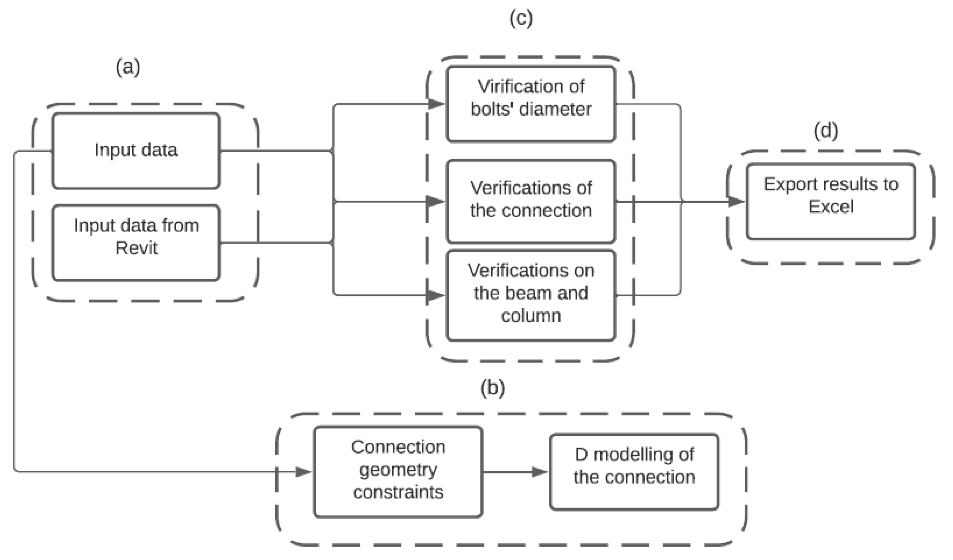
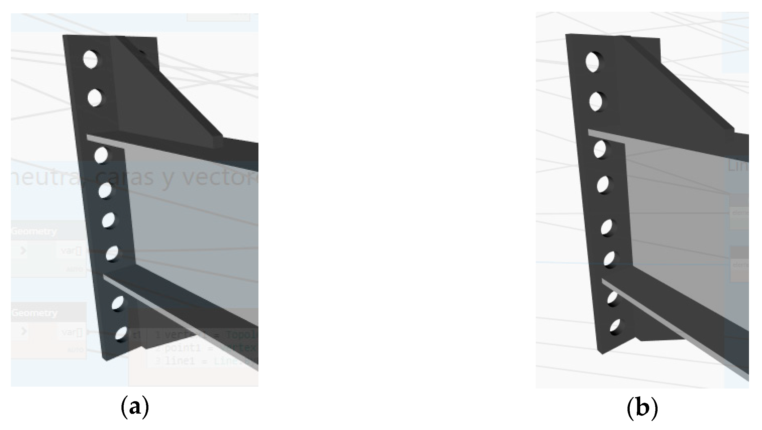
4.1. Design and Development of the Solution

The interaction between the software programs is presented in Figure 4. Revit allows the profiles used for the beam and column elements of the structure to be entered and allows the parametric information of these elements to be subsequently imported through Dynamo for use in the script programmed in it. The design, which has been imported from Dynamo, is then supplemented by Refinery, which provides solutions from the combined data generation. The data combinations are combinations of the connection data that are made through Refinery considering the existing restrictions in terms of geometry, diameter, number and spacing of bolts. Finally, after the iterative process, the results of the script are brought into an Excel spreadsheet that was previously configured to determine whether the delivered solution meets regulatory requirements.
Figure 5 shows a general description of the script programmed in Dynamo. It contains twenty verifications to calculate, which are classified into three groups for better understanding.
To begin the process, the input data must first be entered, as shown in Figure 5 in box (a), for modeling both the plate and the elements to be used from Revit. First, using Revit, the column and beam profiles that make up the structure must be selected, and then, through Dynamo, the parameters of these elements are imported, such as the material, width, length, and thickness of the flange and web. Then, a , b , c , d , e , f , d i a m and t p are assigned as the input data. Figure 6 shows the variables, which are listed below. These variables are then used as dimensions to generate the 3D model of the end-plate connection, for which nodes called sliders are used, which allow the variables to be restricted in terms of the minimum and maximum values that they can take. At the same time, they define the range of variation so that later, using Refinery, values can be selected within these intervals, providing combinations of data and possible solutions.
In Figure 6, a simplified model of the plate is shown to give a better visualization of the variables belonging to the input data used for its 3D modeling.
In this figure, we have the following:
  • a : vertical distance between the outer end bolts and the edge of the end plate
  • b : vertical distance between the inner and outer bolt rows
  • c : vertical distance from the outside of the tension flange to the nearest outside bolt row
  • d : vertical distance from the inside of the tension flange to the nearest inside bolt row
  • e : vertical distance between the rows of interior and exterior bolts, which for the purposes of the investigation will be equal to the variable b
  • f : horizontal distance between the outer bolts and the edge of the end plate
  • g : horizontal distance between bolts
  • d i a m : bolt diameter
  • t p : plate thickness
Table 2 below shows the restrictions represented by the standard for each variable.
For the d i a m variable, a range between 16 [mm] and 36 [mm] was used, and for the t p variable, a range between 2 [mm] and 25 [mm], which corresponds to the minimum and maximum commercial values of both the diameter and thickness of the plate, was used. However, for code optimization purposes, the values within the range can be random, with a minimum variation of one unit. For variables a and f, d e m i n and d e m a x are stipulated by the standard.
Using these dimensions, the geometry of the connection was generated, as shown in Figure 5b, with the respective restrictions indicated by the regulations, and 3D modeling of the connection was performed. To achieve this, we began by modeling a rectangular prism corresponding to the connection plate and base element from which the model was generated. Then, four coordinate points were defined within this prism on the same vertical line. The geometry of the circumference was assigned, and thickness was added later in such a way that these points acquired the geometry of cylinders passing through the entire rectangular prism. These cylinders were then configured so that they were no longer solid and cut through the plate, leaving holes at the initially indicated coordinates. These were the bolt holes. Finally, symmetry was applied both in the Z axis and in the Y axis, forming a plate with 16 holes. To give context to the connection, the column and beam element were transferred from Revit to Dynamo, and a vector was applied to translate the 3D model of the plate toward the union of both elements so that the connection could be clearly understood. A model of the complete structure was produced.
The nodes of the input variables mentioned above, which correspond to the dimensions of the connection, were defined with the option called “Is input,” which allows these data to no longer represent nodes with fixed values and to vary in such a way that they can comply with the proposed restrictions.
As an example, the verification of the bolt shear rupture strength in the compression flange is explained, calculated as shown in Equation (1).
R n u b o = n b o   F n v   A b o
where:
  • n b o : number of connection bolts in the compression flange, i.e., 8 for the purposes of this study;
  • F n v : nominal strength of the bolts;
  • A b o : gross bolt area in cm 2 , represented in Equation (2).
A b o = ( π   d i á m 2 4 100 )
These equations are incorporated into the script for each of the corresponding nodes. Finally, for the verification to be correct, Equation (3) must be fulfilled.
V u ø   R n u b o
where:
  • ø: resistance factor, i.e., 0.9 for the purposes of this study;
  • V u : shear force at the center of the plastic hinge.
Once the equations have been implemented, the node is generated that delivers the result of the verification, which is calculated by subtraction, as shown in Equation (4).
0 V u ø   R n u b o
This node is defined in Dynamo as “Is output,” and the variable referring to the diameter of the bolt found in Equation (2) is defined as “Is input.” This is done for each of the verifications, where the variables that belong to the input data (in the case of the example, the diameter of the bolt) are configured as “Is input” and the node that delivers the result of the verification calculated by subtraction is assigned as “Is output.”
By defining the variables mentioned above as “Is input” and “Is output,” generative design is implemented, since Dynamo can be complemented with Refinery to carry out the study. For this project, the Refinery option called “Randomize” was used, which consists of generating a specific number of design options, established by the user, by randomly assigning a value within the defined range to each of the input parameters. To generate the results, the “Number of solutions” and “Seed” boxes must be configured. The first refers to the number of options that the program will generate, and the second refers to a random seed or number to start randomization, where the more it increases, the more the solutions vary among themselves. After configuring the options, the “Generate” option is selected, and Refinery delivers as a result the number of random data combinations that the user established, which are imported one by one to Dynamo and calculated in the script.
Given that the delivered solutions were generated by combining the data at random, an Excel spreadsheet configured to indicate whether the values resulting from the subtraction of the verifications were greater than zero and thus determine whether the delivered solutions met the requirements had to be included. Restrictions were imposed at the beginning. For this purpose, a part of the program was implemented in Dynamo so that the results of the calculated verifications were automatically exported to the Excel spreadsheet, as shown in Figure 5 in box (d). The spreadsheet was previously configured so that each checkbox would turn green if the data combination of the solution complied with the requirement for all the results to be greater than zero and would turn red in cases of noncompliance. This must be done for each solution delivered to the study by Refinery: once the solution data have been imported into Dynamo, the number corresponding to the position of the column in which the verification results should arrive is changed in the script to the Excel spreadsheet. This is done manually, and then the program is run.
The input data, such as the profiles to be used in the structure, type of steel, grade of bolts and loads on the connection to be designed, were configured to generate a case study and test the operation of this method. An IPE-450 profile was used for the beam and an HEB-340 profile for the column; therefore, the ranges of the input variables were defined as shown in Table 3. The upper and lower bounds shown in Table 3 for the model variables were chosen considering the geometric limitations imposed by the dimensions of the beam and column of the connection, the limits imposed by the standards for the minimum separations between the bolts and of the bolts with respect to the edges of the end plate, and with respect to the parts of the beam. The only value that was assumed based on common sense was the maximum for distance a, which was established for an end plate that extends 150 mm beyond the last line of bolts, measured in both the horizontal and vertical directions.
The minimum value that the variables could take was calculated considering the diameter of the smallest bolt, i.e., 16 mm. For the maximum values, although they are delimited by standards, some considerations were used in this study to further limit the ranges and provide a greater chance of obtaining solutions that met the constraints. These considerations were that variables a and b should not be greater than 2/3 of the width of the column, while variables c , d and f should not be greater than half the width of the column.
A type of ASTM A36 steel was used for both the beam and the column. The bolt grade was ASTM A325M with a span of the beam member of 6 m, a permanent load (D1) of 13,149.24 kN, load of use (L1) 20,833.99 kN and seismic load (E1) 15,962.94 kN. The different types of loads, as well as their combinations, have been defined according to the work of Ambiado et al. [47], in which the reader will be able to find the details on how these loads have been determined. Once all the input data were entered in Dynamo, the study was generated in Refinery, where it was established that it would deliver a total of 50 solutions with a seed value of 1. When the generated results were obtained, the solutions were imported to Dynamo, the position of the column was changed, and script was run to import the results of the verifications into the Excel spreadsheet. This was repeated for all 50 solutions generated.
The 50 solutions obtained gave the result “Does not comply,” which may be due to the “Randomize” option used in Refinery, which, as mentioned above, takes the parameters and generates random data combinations; it does not look for optimized solutions according to the problem. Although Refinery has the “Optimize” option, it was not possible to use it. This may have been due to the recent incorporation of Refinery within Dynamo, as it may not have been fully operational. For this reason, the ranges of the input variables were progressively adjusted until the study generated solutions that met the constraints. The new ranges of variation are shown in Table 4, with which the final study was carried out.
The results obtained were 11 end-plate connection designs that were determined to comply with the constraints of the verifications. The input variables of the solutions can be seen below in Table 5.
The geometry of each of these can be represented within the same Dynamo script. As an example, the geometry of two of the 11 solutions that comply is shown in Figure 7.
From the solutions obtained that comply, the most appropriate option can be selected according to the requirements of the project.

4.2. Verification and Validation

To verify and validate this method, the verification system proposed by Ambiado was used, from [13] as mentioned above, in which the data of the 11 solutions obtained that complied were entered. For this purpose, in the Excel spreadsheet to which the results of Dynamo were exported, a filter was made according to the solutions that complied and those that did not, and the input data of the solutions that complied with the imposed restrictions were extracted.
The extracted data corresponded to the inputs a , b , c , d , b p , d i a m , t p , the section of the beam and the column, the material to be used, the weight of the member and the loads that would influence the connection, which were entered into the spreadsheet to be used for verification. The connection was then designed. Once the inputs were entered, a button was pressed, and the spreadsheet calculated whether the entered data complied with the verifications. This was indicated with a green checkmark if the proposed design was correct and with a red cross otherwise. This was done with each of the solutions that met the initial constraints.
The spreadsheet indicated two incorrect solutions marked with red crosses among the 11 solutions, corresponding to the fact that the structure must be reinforced by placing stiffeners, continuity plates, and double-reinforcement plates. These would need to be calculated later, since as mentioned above, for the purposes of this research, they were not considered within the generative design process.

5. Conclusions

From this research, it was possible to develop a design method for the prequalified end-plate connection that allowed us to automate the process and reduce the design time considerably. By programming the initial restrictions that must be fulfilled, the effort applied in estimating the initial values can be optimized, and the designs can be subsequently verified to achieve the final design. This is beneficial for the AEC industry, since the process was carried out in a BIM environment, making it possible to use tools such as Revit, which provide greater efficiency by integrating different processes and can be extended by tools such as Dynamo and Refinery, which make it possible to complement the process with generative design. This form of design is a new alternative that improves the design process, since the manual iterations and individual verifications are replaced by multiple solutions, from which the user can choose the connection design that best suits his or her needs, such as choosing the one that contains less material and thereby saving costs in joining the structure.
This method can be used by companies in the AEC industry as well as engineering professionals who need to dimension and provide solutions for the design of joints in metal structures. In its use, it must be considered that licenses for both Excel and Revit are necessary, as Revit allows access to Dynamo and Refinery, and the script file and the Excel spreadsheet that allow final verification of the solutions are also needed.
Among the difficulties that Refinery presented was the referencing of images, which may be because the script is very complex or because the new version of Refinery included in Dynamo does not work properly and causes some errors. These errors have also been commented on in online forums dedicated exclusively to addressing doubts and problems that users have in working with the software, but solutions for the problem have not been found. Therefore, Refinery is not currently friendly to carrying out projects with generative design: it requires modifications and improvements, as its interoperability with Dynamo and Revit makes it a potential tool for developing projects in the AEC area with this new design process.
For the purposes of this project, it can be concluded that the use of Revit software did not provide an adequate solution, considering that Dynamo does not allow the parameters of the connection components to be directly imported and that to provide solutions, the 3D geometry had to be modeled directly in Dynamo, a process that could be avoided with better interaction between the software. The software used is directly designed for analysis and can be combined with generative design without having to generate the analysis script with the modeling software, as was done in this research. Thus, because it entails a significant effort by not allowing simple application or a union between structural analysis and generative design, it raises the question of whether it is worth developing this type of program if the correct tools or software do not have total operability. Therefore, the software should be improved along these lines for future research to generate better interaction between software, not only for one platform but several other platforms. Regarding the results, most of the designs obtained did not comply with the verifications because, as mentioned, the options used did not indicate that optimized solutions should be sought; therefore, as they were random, some geometrically incompatible designs were obtained. On the other hand, among the solutions obtained that met the requirements, there was little geometric difference between them; therefore, in the final design chosen for the project, no great difference in cost would exist between the options. The geometry of the doubler plates, continuity plates and stiffeners of the end plate of the connection could be optimized through other procedures that are outside the scope of this work, for example, using the stress distribution through a more detailed connection-components analysis.
A limitation of this work was not to evaluate quantitative variables to compare the proposed generative design method with the traditional design method. Therefore, it is proposed as a future line to identify quantitative variables of interest and perform a simulation of a team designing in a traditional way and another based on the proposed generative design. Some metrics of interest that could be evaluated would be design time, documentation time, number of negative iterations, and degree of satisfaction with the solution, among others.
As future lines of research, it is recommended that a new geometry for the end-plate prequalified connection be implemented, both for the plate and for its reinforcements. A completely different design from the known one could be used, without the usual rectangular shape, with a nonsymmetrical bolt position, with reinforcement plates, or involving more creative shapes, among other options. This is possible because there are no studies that prove that the operation of this connection can fail if it does not have the commonly designed geometry and Dynamo could solve this problem, considering that any type of connection can be modeled on the platform, including the geometry and associated parameters within it. Additionally, even more efficient options could be generated. It would be innovative for the AEC industry to create asymmetrical options in their designs, and beneficial discoveries could be made if favorable results were obtained. Starting from the current steel connections, the proposed methodology could be tested in other types of prequalified connections and then expanded to other applications.

Author Contributions

Conceptualization, R.F.H. and J.C.V.; methodology, R.F.H.; software, D.H.; validation, D.H., R.F.H. and J.C.V.; formal analysis, D.H., R.F.H. and J.C.V.; investigation, D.H., R.F.H. and J.C.V.; resources, D.H.; data curation, D.H.; writing—original draft preparation, D.H.; writing—review and editing, R.F.H. and J.C.V.; supervision, R.F.H. and J.C.V. All authors have read and agreed to the published version of the manuscript.

Funding

This research received no external funding.

Data Availability Statement

Data are available from the authors.

Acknowledgments

The authors wish to thank the Pontificia Universidad Católica de Valparaíso for financing the publication of this paper.

Conflicts of Interest

The authors declare no conflict of interest.

References

  1. Guerrero, S.; Angarita, C. Creación de una Herramienta de Chequeo de Conexiones Precalificadas con Verificación de la Norma Vigente. Bachlor’s Thesis, Franciso Jose de Caldas University, Bogotá, Colombia, 2019. [Google Scholar]
  2. Pannillo, G.; Vielma, E.; Ocanto, W.; Vielma, J.C. Development and programming of end-plate 4E and 8ES connections in accordance with the ANSI/AISC 358-16 regulations. Rev. Int. Ing. Estruct. 2020, 25, 39–60. [Google Scholar] [CrossRef]
  3. Pannillo, G.; Gutiérrez, O.; Vielma, J.C. Development and programming of double-tee earthquake-resistant connections (double-tee moment connections) in accordance with the ANSI/AISC 358-16 code. Rev. Int. Ing. Estruct. 2018, 23, 189–207. [Google Scholar] [CrossRef]
  4. Pannillo, G. Development and programming of seismic-resistant connections type BFP and RBS in accordance with the Ansi/Aisc 358-16 code. Gac. Técnica 2018, 19, 51–68. [Google Scholar] [CrossRef]
  5. Gallegos, M.; Nuñez, E.; Herrera, R. Numerical study on cyclic response of end-plate biaxial moment connection in box columns. Metals 2020, 10, 523. [Google Scholar] [CrossRef]
  6. Díaz, C.; Victoria, M.; Martí, P.; Querin, O.M. FE model of beam-to-column extended endplate joints. J. Constr. Steel Res. 2011, 67, 1578–1590. [Google Scholar] [CrossRef]
  7. American Institute of Steel Construction. Prequalified Connections for Special and Intermediate Steel Moment Frames for Seismic Applications; No. 1; American Institute of Steel Construction: Chicago, IL, USA, 2020. [Google Scholar]
  8. Delgado, C.; Garza, L.; Cruz, R. Conexiones Precalificadas en COLOMBIA. Master’s Thesis, Universidad Industrial De Santander, Bucaramanga, Colombia, 2017. [Google Scholar]
  9. Zhou, F. Model-Based Simulation of Steel Frames with Endplate Connections. Ph.D. Thesis, University of Cincinnati, Cincinnati, OH, USA, 2005. [Google Scholar]
  10. Shi, G.; Shi, Y.; Wang, Y.; Bradford, M.A. Numerical simulation of steel pretensioned bolted end-plate connections of different types and details. Eng. Struct. 2008, 30, 2677–2686. [Google Scholar] [CrossRef]
  11. Muñoz-La Rivera, F.; Vielma, J.C.; Herrera, R.F.; Carvallo, J. Methodology for Building Information Modeling (BIM) Implementation in Structural Engineering Companies (SECs). Adv. Civ. Eng. 2019, 8452461. [Google Scholar] [CrossRef]
  12. Morrison, M.; Quayyum, S.; Hassan, T. Performance enhancement of eight bolt extended end-plate moment connections under simulated seismic loading. Eng. Struct. 2017, 151, 444–458. [Google Scholar] [CrossRef]
  13. Hong, J.K.; Park, Y.C.; Sim, H.B. Cyclic Perfrmance of Easy Quality (EQ) Moment Connections as an Intermediate Steel Moment Frame. Int. J. Steel Struct. 2019, 19, 1272–1282. [Google Scholar] [CrossRef]
  14. Incelli, F.; Cardellicchio, L. Designing a steel connection with a high degree of disassembly: A practice-based experience. J. Technol. Archit. Environ. 2021, 104–113. [Google Scholar] [CrossRef]
  15. Maini, D. Up and Running with Autodesk Advance Steel 2021: Volume 1; CreateSpace Independent Publishing Platform: Scotts Valley, CA, USA, 2020. [Google Scholar]
  16. Ismail, R.E.S.; Fahmy, A.S.; Khalifa, A.M.; Mohamed, Y.M. Numerical study on ultimate behavior of bolted end-plate steel connections. Lat. Am. J. Solids Struct. 2016, 13, 1–22. [Google Scholar] [CrossRef]
  17. Ghassemieh, M.; Jalalpour, M.; Gholampour, A.A. Numerical evaluation of the extended endplate moment connection subjected to cyclic loading. Curr. Adv. Civil. Eng. 2014, 2, 35–43. [Google Scholar]
  18. Díaz, G. Aplicaciones del Diseño Generativo en la Ingeniería Estructural. Bachelor’s Thesis, Pontificia Universidad Católica de Valparapiso, Valparaíso, Chile, 2020. [Google Scholar]
  19. Buonamici, F.; Carfagni, M.; Furferi, R.; Volpe, Y.; Governi, L. Generative Design: An Explorative Study. Comput. Aided Des. Appl. 2020, 18, 144–155. [Google Scholar] [CrossRef]
  20. Cascone, F.; Faiella, D.; Tomei, V.; Mele, E. A Structural Grammar Approach for the Generative Design of Diagrid-Like Structures. Buildings 2021, 11, 90. [Google Scholar] [CrossRef]
  21. Dzwierzynska, J. Rationalized Algorithmic-Aided Shaping a Responsive Curvilinear Steel Bar Structure. Buildings 2019, 9, 61. [Google Scholar] [CrossRef]
  22. Li, B.; Tang, W.; Ding, S.; Hong, J. A generative design method for structural topology optimization via transformable triangular mesh (TTM) algorithm. Struct. Multidisc.Optim. 2020, 62, 1159–1183. [Google Scholar] [CrossRef]
  23. Liao, W.; Lu, X.; Huang, Y.; Zheng, Z.; Lin, Y. Automated structural design of shear wall residential buildings using generative adversarial networks. Autom. Constr. 2021, 132, 103931. [Google Scholar] [CrossRef]
  24. Shen, Q.; Vahdatikhaki, F.; Voordijk, H.; van der Gucht, J.; van der Meer, L. Metamodel-based generative design of wind turbine foundations. Autom. Constr. 2022, 138, 104233. [Google Scholar] [CrossRef]
  25. Silveira, M.V.G.; Paini, B.; Bitencourt, L.A.G., Jr.; Das, S. Design and experimental investigation of deep beams based on the Generative Tie Method. Eng. Struct. 2022, 255, 113913. [Google Scholar] [CrossRef]
  26. Korus, K.; Salamak, M.; Jasiński, M. Optimization of geometric parameters of arch bridges using visual programming FEM components and genetic algorithm. Eng. Struct. 2021, 241, 112465. [Google Scholar] [CrossRef]
  27. Herath, S.; Haputhanthri, U. Topologically optimal design and failure prediction using conditional generative adversarial networks. Numer. Meth Eng. 2021, 122, 6867–6887. [Google Scholar] [CrossRef]
  28. Ma, X.; Wang, F.; Aage, N.; Tian, K.; Hao, P.; Wang, B. Generative design of stiffened plates based on homogenization method. Struct. Multidisc. Optim. 2021, 64, 3951–3969. [Google Scholar] [CrossRef]
  29. Wang, H.; Du, W.; Zhao, Y.; Wang, Y.; Hao, R.; Yang, M. Joints for treelike column structures based on generative design and additive manufacturing. J. Constr. Steel Res. 2021, 184, 106794. [Google Scholar] [CrossRef]
  30. Liu, H.; Zhang, Y.; Lei, Z.; Li, H.X.; Han, S. Design for Manufacturing and Assembly: A BIM-Enabled Generative Framework for Building Panelization Design. Adv. Civ. Eng. 2021, 13, 5554551. [Google Scholar] [CrossRef]
  31. Tafraout, S.; Bourahla, N.; Bourahla, Y.; Mebarki, A. Automatic structural design of RC wall-slab buildings using a genetic algorithm with application in BIM environment. Autom. Constr. 2019, 106, 102901. [Google Scholar] [CrossRef]
  32. Angulo, C.; Díaz, K.; Gutiérrez, J.M.; Prado, A.; Casadey, R.; Pannillo, G.; Muñoz-La Rivera, F.; Herrera, R.; Vielma, J.C. Using BIM for the assessment of the seismic performance of educational buildings. Int. J. Saf. Secur. Eng. 2020, 10, 77–82. [Google Scholar] [CrossRef]
  33. Muñoz-La Rivera, F.; Vielma, J.C.; Herrera, R.F.; Gallardo, E. Waste Identification in the Operation of Structural Engineering Companies (SEC) According to Lean Management. Sustainability 2021, 13, 4249. [Google Scholar] [CrossRef]
  34. Ambiado, E. Automatización y Optimización de Diseño de Conexión de Placa Extrema Extendida 8ES a Través de los Análisis Lineal y no Lineal. Bachelor’s Thesis, Pontificia Universidad Católica de Valparaíso, Valparaíso, Chile, 2020. [Google Scholar]
  35. Velasco, R. Estudio de la Aplicación del Diseño Generativo al Diseño Conceptual Arquitectónico. Bachelor’s Thesis, Universitat Politècnica de València, Valencia, Spain, 2015. [Google Scholar]
  36. Bohnacker, H.; Gross, B.; Laub, J. Generative Design: Visualize, Program, and Create with Processing; Princeton Architectural Press: New York, NY, USA, 2012. [Google Scholar]
  37. ASCENT. Autodesk Advance Steel 2021 Fundamentals: Autodesk Authorized Publisher; ASCENT Center for Technical Knowledge: Carlottesville, VA, USA, 2020. [Google Scholar]
  38. Acuña, J.; Sotelo, H. Software libre para el diseño de conexiones metálicas de acuerdo con la NSR-10. J. Chem. Inf. Model 2014, 138. [Google Scholar]
  39. Bentley. RAM Connection. Available online: https://www.bentley.com/en/products/product-line/structural-analysis-software/ram-connection (accessed on 20 December 2021).
  40. IDEA Statica. Available online: https://www.ideastatica.com/ (accessed on 20 December 2021).
  41. Autodesk. Revit. Available online: https://www.autodesk.com/products/revit/ (accessed on 20 December 2021).
  42. Autodesk. Fusion 360. 2015. Available online: http://www.autodesk.com/products/3ds-max/overview (accessed on 20 December 2021).
  43. Grasshopper. Available online: https://grasshopper.app/es_419/ (accessed on 20 December 2021).
  44. Autodesk. Robot Structural Analysis Professional. 2015. Available online: http://www.autodesk.com/products/3ds-max/overview (accessed on 20 December 2021).
  45. Trimble. Tekla Structures. Available online: https://www.tekla.com/la/productos/tekla-structures (accessed on 20 December 2021).
  46. Dynamobim. Dynamo. Available online: https://primer.dynamobim.org/es/ (accessed on 20 December 2021).
  47. Ambiado, E.; López, A.; Vielma, J.C. Numerical evaluation of prequalified end-plate connections used in a framed steel industrial structure. Metals 2021, 11, 243. [Google Scholar] [CrossRef]
Figure 1. Generative design process. Source: adapted from [35].
Buildings 12 01579 g001
Figure 2. Traditional design process. Source: adapted from [35].
Buildings 12 01579 g002
Figure 3. Research methodology. Source: the authors.
Buildings 12 01579 g003
Figure 4. Scheme of interaction between the software. Source: the authors.
Buildings 12 01579 g004
Figure 5. Script outline. Source: the authors.
Buildings 12 01579 g005
Figure 6. Geometric variables of the connection plate. Source: the authors.
Buildings 12 01579 g006
Figure 7. Geometry solutions for the end-plate connection: (a) geometry solution 1; (b) geometry solution 5. Source: the authors.
Buildings 12 01579 g007
Table 1. Useful software for steel connection design. Source: the authors.
SoftwareGenerative DesignBIMDescription
Advance SteelNoYesAutomates the process of designing structural steel connections based on preconfigured parametric connections. Allows interaction with other software [15].
RAM ConnectionNoNoAnalyzes, designs and optimizes any type of connection for structural steel joints [39].
IDEA Statica ConnectionNoYesPerforms analysis and structural design of metallic connections and calculation of connections based on finite elements. Allows interaction with other software [40].
RevitYesYesProduces 3D modeling; architectural, structural and MEP design; documentation; and coordination. Allows interaction with other software [41].
Fusion 360YesYesCreates mechanical and technical 3D models to meet the needs of industrial designers. Offers parametric, direct, and free-form modeling [42].
GrasshopperYesNoDifferent types of design and 3D modeling can be generated, as well as programming and performing highly complex algorithms. Allows parametric and generative design [43].
Robot Structural AnalysisYesYesCreates strong, buildable designs, enables structural load analysis, and verifies regulatory compliance. Can design steel connections [44].
TeklaNoYesAllows collaborative work between different disciplines in construction projects, with all the information included in a 3D model. It is used in the design, detailing and information management of projects [45].
Table 2. Variable constraints of the connection plate geometry. Source: the authors.
VariableRestrictions
a d e m i n   a   d e m a x
b d i a m 8 3   b b m i n ( 24   t p , 300 )
d i a m 8 3   b b m i n ( 14   t p ,   180 )
c d i a m 25 d i a m + 13 c
d i a m 25 d i a m + 19 c
d d i a m 25 d i a m + 13 d
d i a m 25 d i a m + 19 d
f d e m i n   f   d e m a x
g d i a m 8 3   g b f
Table 3. Input data variation ranges. Source: the authors.
VariableRange [mm]
a ,   f [22, 150]
b ,   e [42.67, 300]
c [29, 150]
d [29, 150]
g [42.67, 190]
Table 4. Input data variation ranges. Source: the authors.
VariableRange [mm]
a ,   f [30, 50]
b ,   e [50, 70]
c [30, 60]
d [30, 60]
g [70, 80]
Table 5. Solution input variables in mm. Source: the authors.
Variable1234567891011
a 4040404540304535404040
b 6570606560557070555555
c 6050554040405055404040
d 3545455530455035356055
e 6570606560557070555555
f 42.54037.532.54535354042.542.542.5
g 7580758070808075707575
t p 1818182018202020201820
d i a m 1616161616162020202020
Publisher’s Note: MDPI stays neutral with regard to jurisdictional claims in published maps and institutional affiliations.

