2. The Geometrical Design Methods
To obtain the precise geometry of the lamellae, the research was carried out using graphical and numerical methods. The main criterion is that the uniformity of the elements needs to be preserved since this is one of the main advantages of lamella structures.
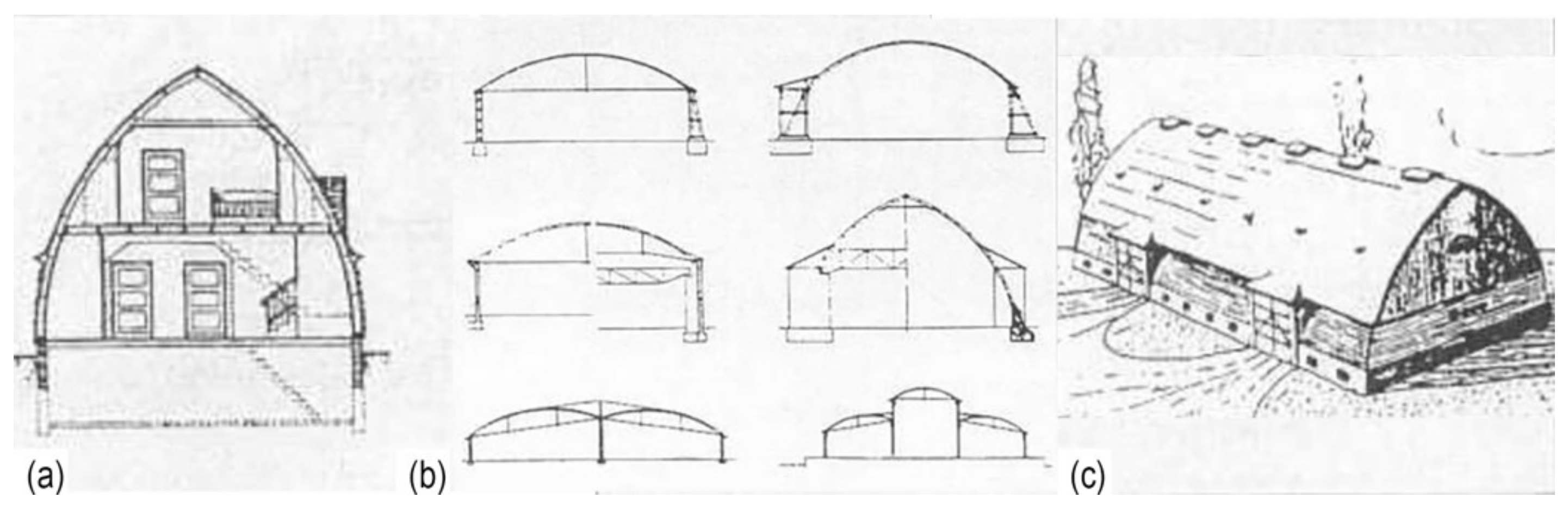
The chosen geometry for the lamella vault is a cylinder surface. The cylinder type is a right circular cylinder, consisting of two of the same parallel bases the shape of a circle. The envelope of a cylinder is a perpendicular surface with all the same and parallel lines equal to the height of the cylinder, which is the vertical distance between the two bases.
The original lamella structure, the Zollinger roof, was designed as two circular cylinder surface segments of the same radius that meet along the ridge. Cylinder surface segments were also used for other types of buildings, such as halls and barns [
5,
7,
9,
11].
2.1. The Graphical Method
2.1.1. Connecting of the Arched Lamellae
The first iteration for the geometrical design of the lamella structure using the graphical method was based on the analysis of the lamella joint. The observed joint is a modification of the original joint for a Zollinger roof. In this joint, the axes of the lamellae intersect at the node, reducing the eccentricity. The three lamellae at the node are connected using steel plates bolted to the lamellae [
20]. The research conducted by engineers Scheer and Purnomo at TU Berlin has shown a layout of the lamella structure, with a span of 21.5 m, a length of 21 m, an arch rise of 6.2 m and arch segments for the angle 120° [
21]. The presented layout was used to design one lamella as a starting point for the geometry of the structure. Lamellae were connected one to another, forming an arch in one direction. The other direction of the lamellae was obtained by the rotation of the arch for 120°. The idea was for all lamellae to be vertical to the floor plane, that is, for the arches to move translationally and to form the vaulted structure.
This design process turned out to be wrong because the lamellae cannot be placed vertically and intersect at the node at the same time. When all the arches made from lamellae are in place, it can be observed that the node of the lamellae is not where it should be placed—each lamella should be connected to the middle of the lamella from the other direction.
Figure 5 shows the details A, B and C with respect to the structure. Detail A shows the only position where it is possible to place a lamella vertically to the floor plane and that is the ridge of the vault. Detail B shows the slight distance of the lamella from the middle of the other one, at 1/4 of the arch, while detail C shows the greatest deviation of one lamella to the middle of the other, observed at the point of support of the structure.
The conclusion is that lamella structures cannot be designed starting from an individual element to the whole assembly because the ends of connecting lamellae do not meet at the middle of the central lamella. It is necessary to start with the whole to obtain a more accurate geometry of the lamellae. Vertical sections through the circular cylinder give an ellipse in the section, which cannot give uniform lamellae.
2.1.2. Projection of the Pattern to the Cylinder Surface
The second iteration was led by the idea that the fastest and simplest way of obtaining the diamond pattern structure on a cylinder surface is to project the pattern to the cylinder surface in software for 3D design, such as Rhino [
22]. The half-radius of the base circle for the cylinder was r = 12.4 m and the length of the cylinder was
l = 21 m. The arch segment had a span of a = 21.5 m and a rise of
f = 6.2 m, giving the length of the arch a
1 = 26 m. The network was made with angles of 60° and 120°, the length of the cylinder surface
l = 21 m and the width equal to the length of the arch segment of the cylinder a
1 = 26 m. The proportions of the cylinder were obtained from the layout by Scheer and Purnomo [
21]. When the network is projected onto the cylinder the disposition of lamellae is obtained. This process is shown in
Figure 6, which shows the detail of the structure with different lengths of lamellae from support to the ridge.
This process of geometrical design has many advantages. It is easily understandable, so it is easy to replicate and apply to any surface. It is not time-consuming, nor it is necessary to always apply the same diamond pattern with angles of 60° and 120°, allowing more design freedom. The lamellae are vertical to the floor plane and intersect at the node, creating a continuous surface for placement of any roof tiling. The only problem is the different lengths of the lamellae, which is why this design does not fulfil the main criteria of the uniform elements. On the other hand, each horizontal segment of the vault has the same lamellae with the same joints, thus making sets of uniform elements. From the ridge to the supports, the length of the lamellae decreases and the angle of the bevelling increases. This structure could be easily prefabricated using a CNC machine for the shaping of the lamellae, in order to decrease the time for their production. If steel plates are used for the joints, a large number of different sets would not be economical to make. However, there are lamella structures constructed like this, such as the ice rink structure in Toronto from 2019 with T-section joints [
23].
2.1.3. Division of Cylinder Surface to Equal Parts
The third iteration for the geometric design was also led starting from the whole to the elements with the aim for the lamellae of the same geometric characteristics to have uniform elements and to fulfil the main criteria. Based on the layout presented by Scheer and Purnomo [
21], a segment of the cylinder surface was divided into equal parts, radially into 20 segments and longitudinally at every 0.75 m to obtain all the nodes of the lamellae. Lamellae rest on supports every 1.5 m and the nodes are placed interchangeably as each lamella connects to the middle of the one from the other direction (
Figure 7a). The nodes were connected with lines passing two lengths of the diamond to obtain the desired length of the lamellae. Two types of lamellae were obtained, the ones 3 m in length and the ones on the perimeter with a length of 1.5 m. These lamellae axes do not intersect at the nodes, so the connection was simulated by a short line, which presented the joint (
Figure 7b). Straight axis lamellae create a structure similar to a folded plate, which was not the idea behind the design. The lamellae needed to have the arched axis that lies on the cylinder surface in order to have all the same lamellae and a uniform surface of the structure.
The arched axis of the lamellae was designed using the two lines, which defined the plane for each lamella in the structure. The ends of the line connecting the nodes and the top of the line presenting the connection define the arch span and rise (
Figure 7d). The most precise geometry is derived this way and the geometrical model fulfils the main criteria. All lamellae have the same geometry and uniform joints, making the production of the elements easy for mass prefabrication.
2.2. The Numerical Method
The geometrical shape that connects all the nodes and divides the cylindrical surface into uniform segments is a helix.
Starting with the parametric equation of a circle [
13]
from which the parametric equation for a circular cylinder is obtained
the parametric equation of the helix can be derived
with pitch
The angle formed by the lamellae is constant and can be derived from the parameters, i.e., the length of the roof—L, the length of the arch—B, the number of cylinder divisions in the X-direction—
m and the number of cylinder divisions in the Y-direction—
n, as shown in
Figure 8a, with its equation given as follows:
The radius of curvature of the helix is
and its arch length is
deriving the abstract angle of the opening of the helix
Based on the elements of the lamella roof structures, as presented in
Figure 8b, the authors of this paper derive the following parametric equations for the two helixes that form the basic geometry of the lamella roof:
-h is the length of the helix for one lamella,
-
α is the angle of the helix needed for one lamella,
-
φ is a variable that defines the segment of the helix (the length of the lamella axis is the angle of 24°);
-k1 is a coefficient that is an even number;
-k2 is a coefficient that is an odd number.
Coefficients k1 and k2 define the movement of the helixes relative to one another for half of the length of a lamella to get the right geometry for each lamella to connect to the middle of the one from the other direction.
In comparison to the parametric equation of the helix by Tutsch [
13], the parametric equations provided by the authors define each lamella axis, taking into account the mutual relation of lamellae. The helix equation by Tutsch defines the helix that follows the segment of the cylinder envelope, not taking into account that the helix from the other direction has to be translated for half of the length of the lamella. The authors define the length of a lamella as a segment of the helix with the variable φ, while the coefficients k
1 and k
2 enable the connection of the lamellae in the middle of the central lamellae. The graphic output of the equations by the authors was developed in Wolfram Mathematica and is presented in
Figure 9.
When applying the numerical method for the geometrical design, the conclusion is that even the infinitely small segment of a helix is a spatial curve. This results in lamellae torqued around their longitudinal axes, which complicates the manufacture, see
Figure 10a. For lamellae to be manufactured, an idealisation is needed. Each segment of a helix needs to be converted to an arch, as it was shown in the graphical method, in order to define a planar curve for the lamellae manufacture. This leads to a slight rotation of the connecting lamellae in the node, as presented in
Figure 10b.
3. The Physical Model of a Lamella Vault
In architecture, physical models help to solve problems during the design process, working in parallel with drawings, 3D models and construction with materials corresponding to the designed structure [
24]. During this process, different aspects of the design can be modified or changed due to the design process on various scales and with a variety of tools. Design problems can be resolved from the level of the node to the structure as a whole. This practice was common in historical constructions when knowledge was acquired by model design and construction and their analysis. This process of constant iterations and relations between designing on a computer and designing a physical model is called complex modelling in contemporary architecture [
25]. The hypothesis is that it helps with better observation and learning about the design.
Following the conclusions of the geometry analysis, the prototype was designed from the lamellae with axes as planar arches to be easily manufactured. The axes of the lamellae intersect at the node, eliminating the eccentricity that appeared at the original joint, making this prototype an improvement of the historical lamella structure.
3.1. The Design of the 3D Model
The first step towards the design of a physical model of a timber lamella vault was the design of a 3D model with all the necessary details of the lamellae and their joints. The model was based on the arched lamellae axes obtained by the graphical method presented in
Figure 7, since the geometry of the axes provided by the numerical method results in torqued lamellae, see
Figure 10a,b. The cross-section was first assigned to the lamella placed vertically to the floor plane and their connecting lamellae in the middle. The ends of the lamellae were bevelled following the vertical axis planes of the lamellae so that the whole cross-section of the connecting lamellae was pressed onto the middle of the central one. The lamellae were then rotated around the axis of the cylinder in order to obtain the whole structure. Thus, all lamellae are the same and all lamellae axes lie in the envelope of the cylinder. Arches along the gables were designed as three-hinged arches. Lamellae pressed onto the gable were cut obliquely by following the vertical plane of the three-hinged arch.
The joints for the lamellae were designed with steel plates bolted to the lamellae. The inspiration was a T-section joint presented in the Timber Construction Manual [
26]. This joint is designed using two steel plates welded to each other to form a T-section. The difference between this joint and the applied one is that, in this design, two steel plates were placed on the outside edges of the lamellae and welded to the central steel plate. The T-section joint is placed inside the lamellae and requires additional shaping, as opposed to the applied joint. The supports were designed as point supports following the same design logic as the joints.
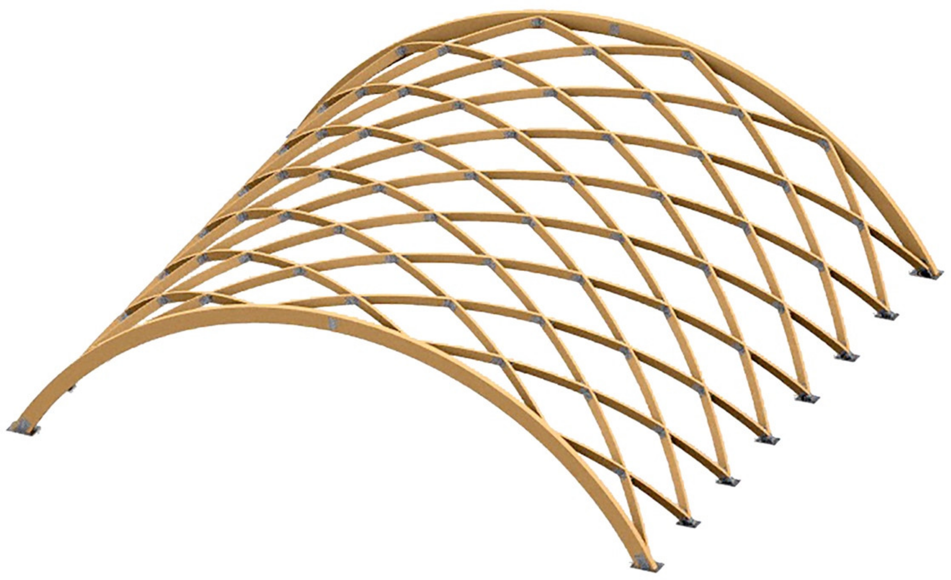
The final design is presented in
Figure 11 and
Figure 12. The 3D model of the structure can be observed in
Figure 11, while
Figure 12 presents floor plans and sections of the structure, providing information about its dimensions.
3.2. Elements for the Physical Model
The designed structure has a span of 10.75 m, it is 3.1 m high and requires 81 lamellae. Based on the position of the lamellae in the structure, six types can be distinguished. All lamellae have the same radius of curvature because they all lie on the cylinder surface. The length of most lamellae is approximately 3 m, except the ones along the perimeter, which are 1.5 m long (
Table 1). Type 1 has a span of 289 cm and it is the most used type in the structure. Type 3 shows the lamellae next to the supports, and type 4 are the lamellae lying on the gable arch. Two special types are types 5 and 6, which lie on the arch and the supports at the same time. The differences between the lamella types are created by the length and the different angles of the bevelling of the ends. The disposition of the lamellae in the diamond pattern with angles 60° and 120° requires this number of types, and it cannot be reduced. The cross-section of the lamellae is width/height = b/h = 6/16 cm.
The structure has six types of joints based on their position inside the structure: two types of lamellae joints, the arch and the lamellae joints, the support joints and two types of arch and lamella support joints. The dimensions of the steel plates depended on the position of the node and its geometry, as well as the position of the bolts according to technical regulations (
Table 2). The width of the steel plates was 3 mm for all of the joints, except for the supports made from 5 mm thick steel plates. The used bolts were M12, class 5.6.
The majority of the lamellae belong to types 1 and 2 (
Table 1) where the bevelling of the lamellae shows that they are mirrored one in reference to the other. Other types of lamellae are derived from types 1 and 2. The same goes for the joints.
3.3. Construction of the Physical Model
The prefabrication of the elements preceded the construction of the designed timber lamella vault. The base for lamellae was made from an arched glued laminated timber beam, with an arch radius of 844 cm and outer edge length of 630 cm. In order to have 81 lamellae, 35 base arches needed to be made. The gable three-hinged arches were made from four equal arched glued laminated timber beams, with an arch radius of 635 cm and an outer edge length of 680 cm. Steel plate joints were prefabricated in a workshop according to the design, out of 3 mm and 5 mm steel plates with mechanically predrilled holes for bolts. The anchor plates were made from 10 mm thick steel plates.
The construction of the lamella vault started with the placement and levelling of the anchor plates, anchored to the ground with M16 anchor bolts. Support joints were welded to anchor plates at the designed positions to provide a good starting point for mounting timber elements. The shaping and placement of three-hinged arches was the next step. The gable arches were measured and shaped on the ground, connected with steel plates at the hinge, and then lifted and placed into the supports. The positions of the joints for the lamella and the arch were measured and marked. The joints were then mounted to the three-hinged arch. To achieve the stability of the gable arch, the first lamellae needed to be placed near the arch supports, as presented in
Figure 13. The construction layout dictated the sequence of the lamellae assembly, starting from one gable to the next, forming one bay at a time in order to check the dimensions and the positions of the lamellae and the joints. The described process of bay-by-bay construction was presented as the best manner of construction for a lamella vault [
10].
The base arches for the lamellae were delivered to the building site where they were measured and bevelled according to the specifications. During the construction, it was concluded that the base arches tended to elongate because of high temperatures, so the position of the joints had to be measured according to the triangle between the edge joints and the middle one. The joints were mounted onto the middle of each lamella on the ground. The lamellae would be then placed at the designed position in the structure and controlled by the position of the stings marking the height of the nodes. The lamellae would be temporarily secured with screws until the whole bay was positioned, after which the holes for the bolts would be drilled and the bolts mounted.
At the beginning of the construction, there was a need for additional supports, since the structure was very unstable. With the increase of the bays, the structure began to adapt to the cylinder shape. The larger number of lamellae showed that every other lamella reinforced the previous one and set its position in the structure. This was observed as a successive relief in the construction process right after the construction of the first bay, and it was confirmed after half of the structure was constructed.
The construction experience contributed to a better understanding of the timber lamella vault. Conclusions were drawn regarding the method of assembly and the preparation of the structural elements. This experience also opened questions related to the modification of the structure.
The construction process and the physical model are shown in
Figure 14.
4. Discussion
Lamella structures are a specific type of spatial structure primarily because of their diamond pattern. They have the advantage of the uniformity of elements, leading to an economical structure that is easily assembled. This pattern creates an unstable system if no additional structural elements are applied. One of the ways to solve this problem is to form moment connections between lamellae. In order to design a lamella structure, the geometry must be precisely defined.
The original joint has a large moment of eccentricity compared to the other types of joints and the load capacity of the bolts connecting the three lamellae at the node is much smaller [
12,
26]. Throughout the years, engineers have suggested a modification of the original joint and have designed a joint with all three lamellae axes intersecting at the node, thus eliminating the eccentricity [
20,
21,
26]. The proposed joints are usually designed with steel plates, having a greater loading capacity than the original one. The geometrical design and the prototype presented in this paper are for the lamella structure where all lamellae axes intersect at the node, and the eccentricity is eliminated.
The chosen geometry of the lamella structure in this paper is a lamella vault. The diamond pattern is applied to the envelope of the right circular cylinder. The material of the lamellae is timber, and the joints are formed out of steel plates bolted to the lamellae.
The discussion in this paper is led by the following criteria:
The geometry of the structure must provide uniformity of all structural elements.
The lamellae must intersect at the nodes to reduce the eccentricity of the joints.
The construction must be simple and performed in a short period.
The designed structure must be economical.
The criteria are derived from the advantages of historical lamella structures, which must not be damaged by the modification of the structure.
The geometrical design of the lamella vault was approached using the graphical method and the numerical method. The numerical method for geometrical design opens the possibility of easy modification of set parameters. The diamond pattern of the lamellae can be applied to any type of surface by following the methodology shown in
Section 2.2. The authors’ numerical method presents a further observation of the specific pattern of lamellae and gives the possibility of adaptation, which would include the interchangeability of the original connection—one lamella connects to the middle of the next one from the other direction. The presented parametric equations can also be used for 3D modelling in different software plug-ins, such as Grasshopper for Rhino. This enables the fast and precise design of the geometrical model [
15,
16,
19]. For the physical model, the axis curves of the lamellae would have to be optimised. The parametric definition of the helix, even for an infinitesimal segment, gives a spatial curve, so it is necessary to modify it into a planar curve—an arch that will define the axis of the lamella for the construction. One of the graphical methods has shown this modification. The presented graphical methods have shown two possible approaches to geometric design: (1) from lamella to the whole structure and (2) from the whole to the lamella. The analysis has shown that the right process of design is the second one and both graphical methods that followed this process have proven successful.
The method of pattern projection to the cylinder surface creates a reasonable structure with all vertical lamellae that intersect at the nodes. This geometry does not fulfil the first criteria since there are numerous sets of uniform lamellae, depending on the density of the structural pattern. This could be overcome by the production of lamellae on a CNC machine, thus reducing the prefabrication time. The number of joint sets would be the same as the number of lamellae sets, so a simple joint must be designed to be easily modified for different angles in the structure. If the elements were to be mass-produced, this structure would have complied with all the criteria except the first one.
The method of division of the cylinder surface into equal parts was applied to the design of the physical model of the lamella vault. This method gives a uniform structure with six types of lamellae and the corresponding joints, no matter the density of the pattern since the types of the elements depend on their position in the structure. The differences among lamellae are created because of different angles for bevelling, which also influences the angles in the joints. Types 1 and 2 are mirrored elements, which are the consequence of the diamond pattern and the angles of 60° and 120°. The number of types could be reduced for one if the pattern was created with 90° angles. This proves that the structure fulfils the first two criteria. The only problem with this structure is the rotation of lamellae at the nodes because the axes of the lamellae intersect at the nodes.
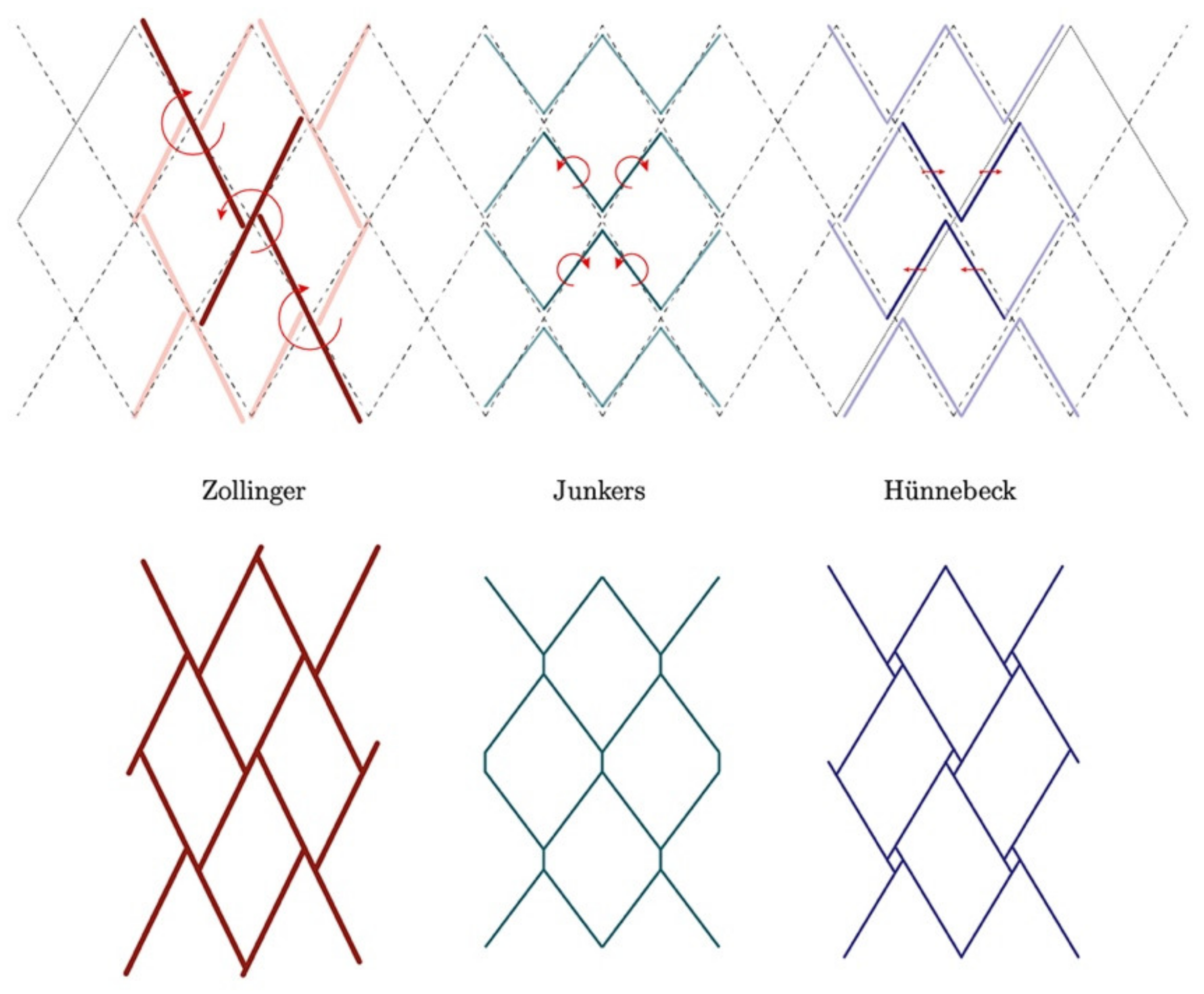
In historical lamella structures, the rotation/translation of the lamellae was applied in the horizontal plane to have all lamellae vertical to the floor [
13]. This resulted in a variety of joints that had large moments of eccentricity, since the lamellae do not intersect at the nodes, but the criteria for uniform elements was fulfilled. The advantage of Junkers’ structure, over the ones of Zollinger and Hünnebeck, was that all the joint elements were the same. In comparison to these structures, the designed joint for the presented physical model has reduced the eccentricity in the node, leaving the axes of lamellae to intersect. On the other hand, the rotation of the lamellae appears in the vertical plane, making a torsional movement around the axis, so they are not vertical in relation to the floor. The rotation of the lamellae at the node is the consequence of the approximation of the arched axis of the lamella corresponding to the helix curve, as presented in
Section 2.1.3 and
Section 2.2. This rotation of the lamellae demands further shaping after the construction is finished, to provide a continuous surface, as it would be for the vertically placed lamellae.
The construction of the physical model for the timber lamella vault with a 10.75 m span and a length of 10.5 m lasted seven days with only three workers. The hypothesis is that five workers would finish the construction in a smaller amount of time, thus also fulfilling the third criterion. The number of workers and the period of construction affect the economy of the structure [
27], i.e., the cost of construction is reduced for a small number of workers and the short construction time. In comparison to standardised timber vaults, this structure is not economical because all the elements are specially designed only for this structure, while standardised vaults use mass-produced elements.
The discussion and analysis of the presented geometry of timber lamella vaults still leave an open question for choosing the best way to design a lamella structure, thus giving the designer the possibility to adapt the structure to its needs.


