Article

The Behaviour of Load-Carrying Members from Cordwood

by
Arvis Brics
1,
Dmitrijs Serdjuks
1,
Marina Gravit
2,
Karina Buka-Vaivade
1,*,
Vadims Goremikins
1,
Nikolai Ivanovich Vatin
2 and
Andrejs Podkoritovs
1
1
Institute of Structural Engineering, Riga Technical University, LV-1048 Riga, Latvia
2
Civil Engineering Institute, Peter the Great St. Petersburg Polytechnic University, 195251 St. Petersburg, Russia
*
Author to whom correspondence should be addressed.
Buildings 2022, 12(10), 1702; https://doi.org/10.3390/buildings12101702
Submission received: 8 September 2022 / Revised: 29 September 2022 / Accepted: 13 October 2022 / Published: 16 October 2022
(This article belongs to the Collection Buildings and Fire Safety)

Abstract

:
With the growing importance of sustainable construction in the world, cordwood is gaining additional interest as a building material for load-bearing structures. The number of studies on cordwood is limited; there is a lack of information on cordwood design methods, including in the case of fire exposure. The design methods for axially compressed load-carrying cordwood members, including in the case of fire action, are described and supplied by the numerical examples. Numerical and laboratory experiments are carried out to clarify the behaviour of cordwood under pressure with different types of binder. For the analysis of cordwood’s load-bearing capacity, the equivalent composite material (rubble masonry) calculation method is proposed. The analytical method for designing cordwood in the case of fire action is based on a combination of the reduced cross-section method and the 500 isotherm method. It is stated that the use of low- or medium-high-strength mortar (up to 10 MPa) for cordwood is the most rational and economical. Additionally, it is shown that 40 cm thick cordwood could be used as a material for load-carrying walls for two-storey buildings and provide very high fire resistance—R180, in the case of a double-sided fire action.

1. Introduction

Green building has become one of the main trends in construction [1,2]. Sustainable construction refers to the use of traditionally adopted and innovative materials and technologically innovative and sustainable solutions, creating a balanced, optimal and friendly living space for people and the environment, thereby promoting more environmentally friendly, economical and social solutions, meeting the comfort and quality requirements of modern living, while, at the same time, looking to the future [3,4,5,6,7,8].
One of the most specific branches of sustainable construction is permaculture, which means sustainable/smart farming. This concept is not limited to farming a garden or a home but also the environment and human activity [9,10]. Among the materials used in construction, permaculture recommends environmentally friendly materials: wood, clay, straw, peat and litter [11,12]. When clearing forests, trees are often cut down in large quantities, which are not used to produce building materials due to their small diameter or other faults. Such materials are disposed of or used as fuel. The green approach reveals the use of wood logs in construction. For example, they can be used as a deck and enclosing structures for small pedestrian bridges (see Figure 1a) or for making cordwood structures. Cordwood attracts significant interest as a structural material in this case.
Cordwood structures are not widely used in practice. Some examples of cordwood use as a structural material can be found in North America and Europe [13,14]. The reduced environmental impact characterises the cordwood structures due to low embodied energy and the possibility of storing CO2. Cordwood is used in structural members subjected to compression, such as walls and columns. Its compressive behaviour was investigated in some studies [15]. The methods for laboratory tests enable the determination of cordwood compressive strength, so the obtained results are also presented [16]. However, the design methods for compressed cordwood wall structures are not shown in detail.
Fire occupies a leading position in disasters [17]. The essential aspect of efficient building protection is the fire behaviour of the construction materials used [18]. Therefore, the behaviour of cordwood walls in the case of fire is also of interest. The cordwood structures are characterised by massiveness and a large cross-section. Usually, cordwood walls are 30–60 cm thick [14], which points towards an increased service life and value of the residual resource of the structure [19]. At the same time, such a stiff structure with diverse geometry creates challenges for structural health monitoring [20,21]. Therefore, the detection of changes in the structure’s material and/or geometric properties over time may be problematic. Massiveness is also one of the reasons for using cordwood mostly only for building single houses.
The lack of design methods for cordwood load-carrying structural members, especially in the case of fire action, is a problem, which can be stated at the current moment. The existing sources [15,16] do not contain a clear description of the design methods used for cordwood load-carrying structural members. The current investigation should present clear information regarding the methods as numerical examples of its application to fix the specified problem.
Therefore, the aim of the current investigation is to investigate the behaviour of axially compressed cordwood specimens. The method for cordwood structural members’ design, considering fire action, should be generalised to achieve the above-mentioned goal of the current investigation. The laboratory experiment and numerical modelling will determine the cordwood specimens’ behaviour depending on the components’ mechanical properties—wood billets and mortar. An in-depth analysis is conducted on the interworking of the elements of cordwood and the development of a calculation methodology based on experimentally obtained specimen test results (see Figure 1b), the finite element (FE) model basis and the conclusions drawn by researchers from the equivalent (alternative) composite material (rubble masonry) from the experimental performance analysis. The possibility of cordwood use for load-carrying structural members should be checked.

2. Materials and Methods

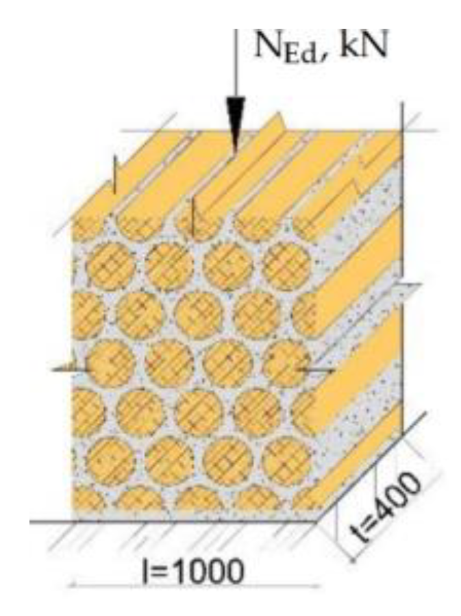
2.1. Analytical Method for the Design of Cordwood

The analysis of the behaviour of cordwood elements and the methods for assessing compressive strength was based on the experimental results of specimen testing, the FEM model and the analysis of an equivalent composite material (rubble masonry). The construction, mechanical properties and structural performance of cordwood wall load-bearing members are similar to rubble masonry, which has long been used in the construction industry. Both structural solutions are formed by aggregates interacting with a binder. Unlike rubble, wood works as the aggregate, while mortar or clay acts as the binder. Consequently, one of the methodologies for cordwood calculation is the analysis of the performance of rubble masonry and the study of the methods for the calculation of structures. This particular strand provides an insight into the behaviour of an analogous structural solution under load and the numerical calculation of such structures, pointing out the components and material properties that should be considered in the calculation.
The main load-bearing material in this composite is the mortar or binder. Consequently, the formula for calculating the compressive strength of cordwood will be developed starting from the maximum compressive strength of the mortar. The characteristic compressive strengths of cordwood can be evaluated by the following formula [15,22]:
σ c , m = f ( σ c , j , max ) = 0.5816 × ln ( σ c , j , max ) + 0.0572 ,
where σ c , m is the characteristic compressive strength of cordwood; σ c , j , max is the maximum compressive strength of the mortar.
The suggested design method for axially compressed cordwood walls is based on the condition formulated in the EN 1996-1-1:2008 for nonreinforced masonry walls:
N Ed N Rd ,  
where N Rd   is design value of the load-carrying capacity of axially loaded cordwood wall, which is determined by Equation (3):
N Rd ϕ × t × f d ,  
where ϕ is a factor, which considers the decrease in cordwood wall design resistance due to the probable eccentricities and the wall’s slenderness; t is the thickness of the cordwood wall; f d is design value of the compressive strength of cordwood.
The design value of the compressive strength of cordwood fd is determined as a relation of the characteristic compressive strength σ c , m and the safety factor ΥM, which is equal to 2.7 [23].
The design value of the load-carrying capacity of axially loaded cordwood wall depends on the wall thickness t and factor ϕ . Factor ϕ shall be determined according to EN 1996-1-1, Section 6, clause 6.1.2.2., and is within the limit of 0.2 to 0.9. The dependence of the design strength of the axially loaded cordwood wall on the wall thickness t and factor ϕ can be described as the second-order polynomial Equation (4), in a case where the thickness of the wall is within the limits of 0.3–0.7 m.
N Rd = f ( t , ϕ ) = 0.00125283 0.00311224 × ϕ + 0.0315476 × t + 814.821 × ϕ × t + 0.0272109 × ϕ 2 0.0416667 × t 2 ,  
The design strength of axially loaded cordwood walls changes from 48.89 to 513.33 MPa if the design value of the compressive strength of cordwood is equal to 2.20 MPa [23]. Therefore, the suggested Equation (4) can predict the design value of the load-carrying capacity of an axially loaded cordwood wall. Equation (4) should also be used to determine the load-carrying capacity of axially compressed cordwood walls in the case of fire action.

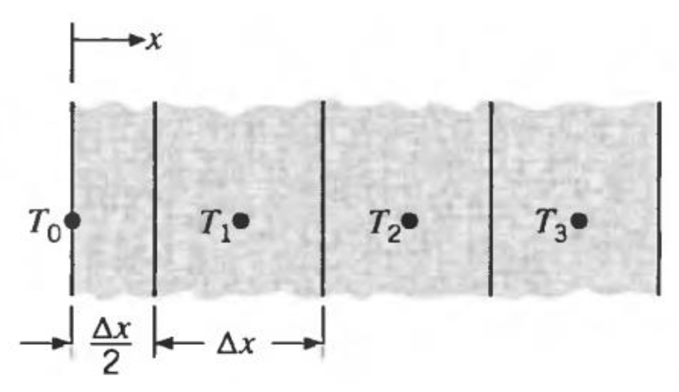
2.2. Analytical Method for the Design of Cordwood in Case of Fire Action

The proposed analytical method for designing cordwood in case of fire action is based on a combination of the reduced cross-section method described in Ref [24] and the 500 isotherm method described in Ref [25].
The simplified calculation method generally reduces the cross-section size to a heat-damaged zone. The damaged mortar’s thickness is equal to the average depth of the 500 °C isotherms in the compression zone of the cross-section.
On the one hand, the remaining cross-section of the timber is defined by the charring depth. The position of the char line should be taken as the position of the 300-degree isotherm.
Since 500 °C isotherms define the strength of the mortar, but 300 °C isotherms define the strength of timber, the worst scenario of 300 °C isotherms should be used to determine the damage by temperature cross-section parameters of the timber–mortar cross-section.
The temperature of the mortar could be determined by the following equations [26].
Heat transfer between external layer and gas
θ 0 p + 1 = 2 α c × Δ t ρ × c × Δ x × ( θ g θ 0 p ) + 2 ε m × σ × Δ t ρ × c × Δ x × ( ( θ g + 273 ) 4 ( θ 0 p + 273 ) 4 ) + 2 λ × Δ t ρ × c × Δ x 2 × ( θ 1 p θ 0 p ) + θ 0 p ,
Heat transfer between internal layers
θ m p + 1 = λ × Δ t ρ × c × ( Δ x ) 2 × ( θ m + 1 p + θ m 1 p ) + ( 1 2 λ × Δ t ρ × c × ( Δ x ) 2 ) × θ m p ,  
where λ is the thermal conductivity; ρ is the density; c is the specific heat; Δt is the time interval; Δx is the layer thickness; ϴ is the temperature; ϴg is the gas temperature; αc is the heat transfer coefficient by convection; εm is the surface emissivity; σ is the Stefan–Boltzmann constant.
Charring depth is defined by the following equation:
d char , 0 = β 0 × t , where β 0 = 0.65 mm/min is the charring rate of softwood timber, and t is time in minutes.
The final reduction in wall thickness, considering the pyrolysis layer after more than 20 min of fire exposure, is defined by the following equation [7]:
d ef = d char , 0 + 7   mm
The strength of the reduced cross-section is determined for normal temperature by applying material safety factors for the fire load case, equal to 1. The scheme of the cordwood layers is shown in Figure 2.
The reduction in the wall cross-section is shown in Table 1 and Figure 3. The cross-section reduction in the case of one-sided fire is not dependent on the wall thickness for walls thicker than 200 mm.
In the case of double-sided fire, the depth of 300 °C isotherms will be dependent on the wall thickness. The reduction in the cross-sections for different wall thicknesses is shown in Table 2. The depth of 300 °C isotherms is not affected by wall thickness for walls thicker than 400 mm.

2.3. Developing Comparison Criteria for Cordwood

As cordwood wall is a composite material in structure, it is possible to assess the influence of each constituent material on the mechanical properties of the newly developed structural solution properties. The filler material is wood, and the binder material is the mortar. To evaluate each of the mechanical properties of the materials in combination and to judge their rational use in the overall structure, it is possible to introduce performance criteria. One such criterion is considered in the study as the strength increase/decrease factor k1(k,j). The factor can be determined by Equation (8). Its essence is to find factor k1(k,j) as the ratio of the total strength of the masonry to the strength of the wood used or the strength of the mortar concerned. This factor establishes the proportion of the materials used for the maximum compressive strength in the constructed parapet wall.
k 1 , ( k , j ) = f c , m f c ( k , j ) ,  
where fc,m is the compressive strength of cordwood; fc,k is the characteristic compressive strength of timber perpendicular to the grain (fc,90,k); fc,j is the characteristic compressive strength of the mortar.
The second performance criterion is the specific strength factor k2, which can be determined by Equation (9).
k 2 = f c , m V m ( f c , j V j + f c , 90 , k V k ) ,  
where Vm, Vj and Vk are volumes of cordwood, mortar and wood, correspondingly.
The introduction of such factors allows an evaluation of the cordwood components’ mechanical properties’ influence on the cordwood compressive strength. It assesses the reserves of each material’s mechanical properties and how much of the strength is used in the overall strength of cordwood. These results provide a rational choice of cordwood components, enabling the maximum compressive strength of cordwood.

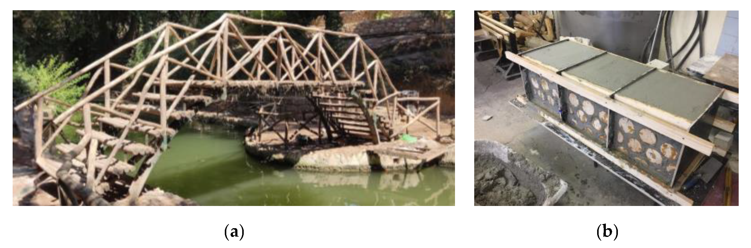
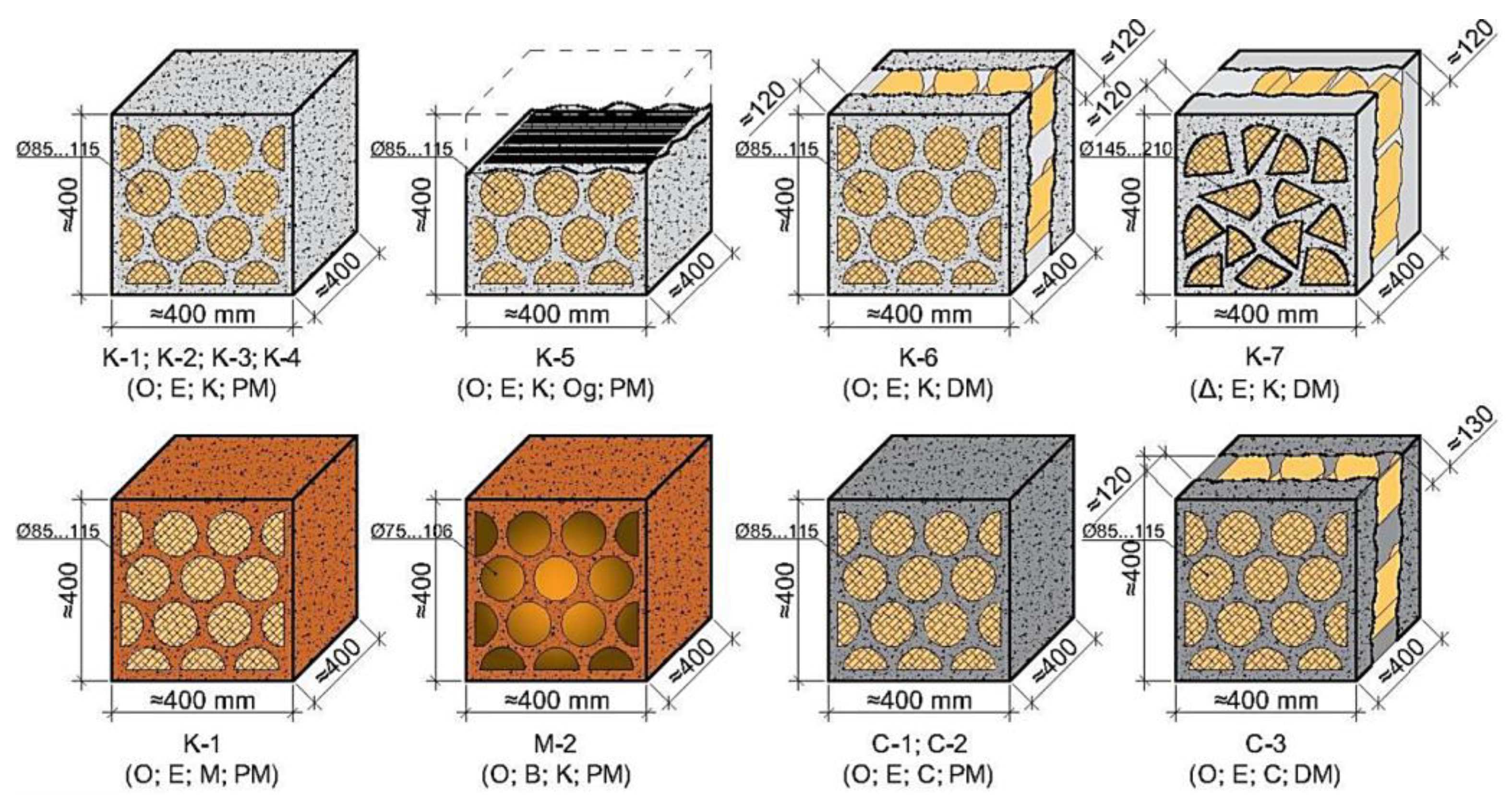
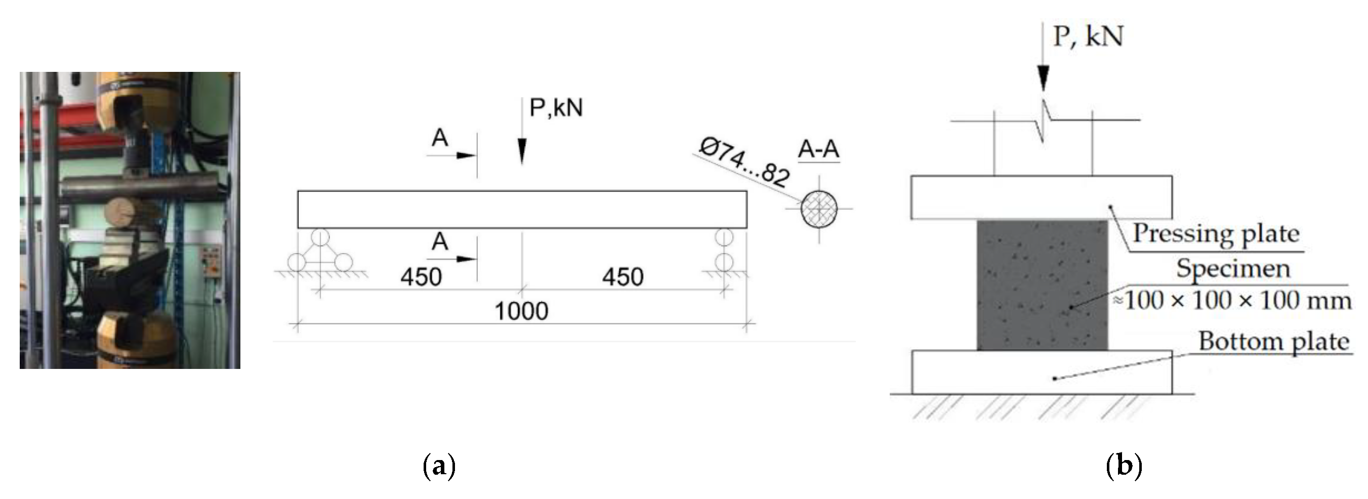
2.4. Description of Laboratory Experiment

The laboratory experiment compared the effects of several types of binders’ and wood billets’ placement on the compressive strength of cordwood. A total of twelve cordwood samples were produced with dimensions of approximately 400 × 400 × 400 mm using birch and spruce wood billets with round and triangular sections bound with lime or cement mortars or clay. Mortars and clay samples (cubes) with dimensions 100 × 100 × 100 mm were prepared separately to determine their mechanical properties. In parallel with the cordwood sample work, the wood’s strength class and the corresponding physicomechanical properties were determined. When the cordwood samples were cured, they were taken to the laboratory for testing. The cordwood and bonding agent specimens were tested using a compression test to determine the maximum compressive force for each specimen. The results obtained were then processed to determine the experimental compressive strength of the cordwood specimens.
Spruce and birch billets with round sections and cross-sectional diameters from 85 to 115 mm and from 70 to 106 mm, respectively, were used. The maximum dimensions of the billets with triangular sections were within the limits of 145 to 210 mm. As the wood was embedded in the binder up to the testing time, it was not treated with special wood preservatives, antiseptics and fire retardants, etc. It should be noted that the billets were selected with a cross-section diameter, so that the cordwood specimen produced would resemble as closely as possible its actual shape when constructing such cordwood houses in real life. Lime and cement mortars and clay were used as masonry binders (Figure 4).
Each of these mortars has its theoretical rationale for the purpose for which they were chosen. It is important that the mortar applied is breathable. The lime mortar chosen (with a composition of Cement:Lime:Sand of 1:3:9) is breathable, highly hydrophobic and water vapour permeable. The samples were also bricked with cement mortar (Cement:Lime:Sand—1:0.5:1) to achieve a high compressive strength of cordwood. Cordwood house construction is considered a ‘green’ construction solution, so the clay (Clay:Sand—1:2) samples of cordwood were prepared. It is important to note that the originally used clay was selected for specimen preparation.
The parameters and designations of all twelve specimens are shown in Figure 5. Three groups of specimens are shown according to the type of binder. Lime was chosen as the binder material for the first group of specimens (from K-1 to K-7). Clay was chosen as the binder material for the second group of specimens (M-1 and M-2).
The designations in brackets of all twelve specimens contain four or five positions. The first one defines the type of wooden billets. The letter O means a round cross-section, but the letter Δ means a triangular one. The second letter defines the spice of the wood. Letters E and B mean spruce and birch, correspondingly. The third letter defines the type of binder material used. Letters K, M and C are used in the cases where lime, clay and cement are used as the binder materials, correspondingly. The fourth combination of letters, PM and DM, is used in the cases where the specimens are completely and incompletely filled with the wood billets, correspondingly. One specimen (K-5) was strengthened with the carbon fibre fabric.

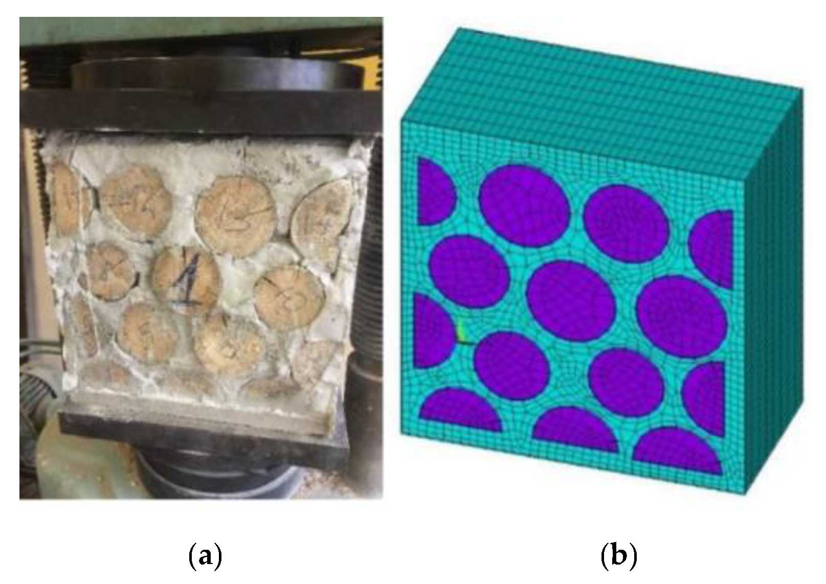
2.5. FEM Modelling of Cordwood Specimens

Specimen C-1 was simulated virtually using FEM realised by the software ANSYS 2019 R1 to verify the experimental results. The specimen’s geometry, the dimensions and position of wood billets, and the physicomechanical properties of the composite elements were obtained experimentally.
Before the destruction of the sample, the cordwood specimens’ dimensions were measured in the laboratory, i.e., the approximate coordinates of the wooden elements’ centre in the frontal plane and the wood billet’s cross-sectional diameter. The modelling starts with creating the geometry, where the outline of the sample is drawn in the software using lines and the arrangement of the wooden elements within it. The model is half shorter in the z-axis direction, and symmetry conditions are imposed. The use of symmetry conditions reduces the number of elements in the model and speeds up the calculation execution. As cordwood is a composite material, it is necessary to define its elements and types. Both elements are rigid and spatial solids. It is necessary to use SOLID-type elements. Mortar (concrete) is chosen as material 1 in the model, so it is assigned the SOLID65 type for calculating concrete structural elements. Wood, on the other hand, is assumed as material 2. Both element types are eight-node elements with three degrees of freedom displacement at each node in the x, y and z directions. The SOLID185 finite element type has ductility, hyperelasticity, tensile stiffness, creep, large displacement and deformation capabilities.
All the necessary parameters were identified for the complete and accurate development of this calculation model, including the numerical values and coefficients relating to mortar cracking, the mechanical properties and the contact surface of the materials. The developed FEM model was loaded with uniform forced displacements until the collapse occurred, and the maximum applied load was read. The obtained results were within the normal limits of the experimentally obtained breaking force. The follow-up FEM in the model was carried out on the specimens’ simulations, determining cordwood’s strength as a function of mortar composition and the choice of timber material—specifically, by keeping the specified mechanical properties of the mortar and varying the strength of the wood used, correspondingly, cordwood. The effect of the materials on the compressive strength of cordwood and its variation was assessed. In this way, various models of cordwood specimens and the failure loads in each case were determined, allowing the simulation of experimental activity in the laboratory where the cordwood specimens were developed and tested.
After defining the materials, the computational model mesh is generated, or the sample is split into finite elements. In short, the areas are subdivided into smaller, proportionally similar parts, and the computer program divides the model into finite elements (Figure 6b).
Once the mesh is generated, setting the appropriate boundary conditions is necessary. A sample of cordwood is loaded in a compression machine where the load was applied uniformly from above. Consequently, the GEM model needs to specify that the bottom plane of the specimen cannot be moved, as no rotation in any axial direction is possible. The lower plane of the specimen is, therefore, clamped; all displacements are forbidden for the nodes belonging to it. Conversely, the upper plane must have the possibility for linear displacements in the Y-axis direction. Since this problem is solved with contact surface conditions, which ensure that the wood billets and concrete work together only in the x and y directions, it is necessary to ensure that the headers have no possibility for linear displacements in the Z-axis direction (see Figure 7a,b). This condition is ensured by the given symmetry boundary conditions.
Before loading the specimen, it is necessary to define the properties of the contact surface between the wood and the concrete to characterise the interaction between the two materials and more accurately represent the deformation processes occurring in the specimen under load. Before defining the contact surface properties, it is necessary to find the corresponding pairs of element contour surfaces between which these properties will then be assigned. The main characteristic of these properties is the coefficient of friction between these two elements, which in this case is μ = 0.62 [27]. Once all the above steps have been carried out, the loads can be applied. In the FEM model, the specimen will be loaded as in the experiment, with forced vertical displacements applied to the upper plane. As the displacements were not applied during the controlled experiment, the maximum value of the displacements is assumed to be 1 mm, up to which the program then performs the calculation in case no collapse of the sample occurs. After the loading conditions have been established, the analysis criteria of the program are defined. Since the calculation is carried out taking into account the cracking and collapse of the concrete, it is difficult to obtain the convergence of the forces. In this case, the convergence of the calculation is checked by the displacement conditions. When the specimen collapses, the calculation of the program is terminated, and the results can be read. The collapsing load is determined; the total normal stresses in the specimen and in the individual elements are considered; displacements and cracks in the concrete structure and other results of interest are obtained. After the design model has been developed and analysed, simulations are carried out to create new specimens with different mechanical properties of the materials or using other strength classes of concrete and wood. Thus, virtual numerical experiments are not needed for new masonry specimens to investigate their performance with material changes in properties. This experimental activity will allow the overall compressive strength of the masonry to be evaluated as a function of the material properties used.

3. Results

3.1. The Numerical Realisation of the Developed Analytical Method for the Design of Cordwood

The analytical calculation checks the possibility of cordwood use in the axially compressed structural members. The fragment of load-carrying cordwood wall with a length of 1000 mm and thickness of 400 mm was considered under the action of axially applied compression force for the purpose. The fragment of the load-carrying cordwood wall was placed on the maximally loaded bottom zone of the first floor of a two-storey residential building with load-carrying cordwood walls (Figure 8). The value of the axially applied compression force was determined by taking into account the following characteristic values of loads: permanent load on the two floors and roof 0.5 kPa, snow load on the roof 1.25 kPa and imposed load on the floor 2.0 kPa [22].
The span of the roof and floor structures is equal to 6 m, and the corresponding design value of the axial compression force, acting on the considered wall fragment Ned, is equal to 226.10 kN.
The design value of the load-carrying capacity of axially loaded cordwood wall NR,d was determined by Equation (3) for the case where the designed compressive strength of cordwood is equal to 0.815 MPa, and factor ɸ is equal to 0.75. The designed load-carrying capacity of axially loaded cordwood wall NR,d was 244.50 kN. The relation of Ned to NR,d is equal to 0.93 and means that the cordwood wall fragment’s load-carrying capacity is provided.
Therefore, it can be concluded that cordwood can be used as a material for load-carrying walls for two-storey buildings.

3.2. The Numerical Realisation of Developed Analytical Method for the Design of Cordwood in Case of Fire Action

The same data from the case study described in Section 3.1 are used. In the case of fire, the load effects could be reduced by ηfi = 0.6 for timber structures and ηfi = 0.65 for masonry structures [24,28,29]. For the case study, a more conservative value of ηfi = 0.65 will be used.
The design value of the axial compression force in the case of fire, acting on the considered wall fragment Nfi,d, is equal to 147.0 kN. The safety factor in fire: γM,fi = 1 (according to Ref [29]); the design strength in case of fire: fd = 2.2 MPa.
In the case of one-sided fire (external wall), for fire resistance R240, the cross-section reduction is 0.163 m (see Table 1). The obtained resistance in the case of fire is NR,Fi,d = 391.1 kN. R240 is ensured.
In the case of double-sided fire (internal wall), for fire resistance R180, the reduction in the cross-section is 0.248 m (see Table 2). The obtained resistance in the case of fire is NR,Fi,d = 250.8 kN. R180 is ensured.

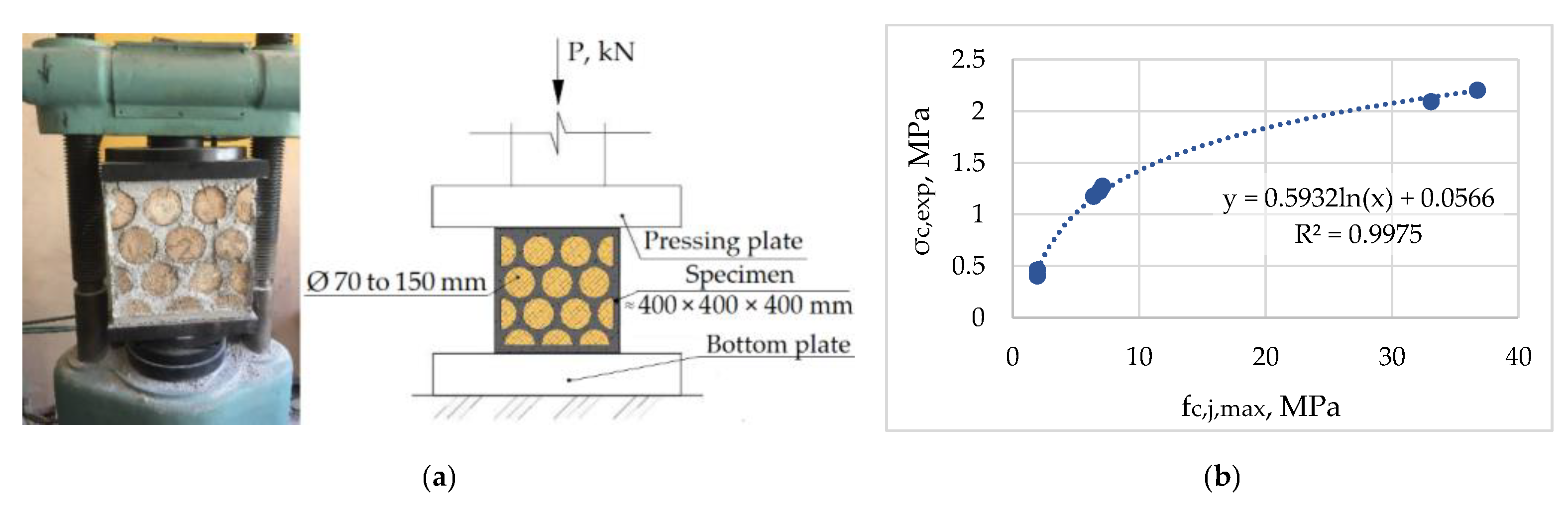
3.3. Results of the Laboratory Experiment

The behaviour of cordwood specimens according to the type of mortar used for joining wood billets was compared by a laboratory experiment. The compressive strength for the prepared cordwood specimens was determined. A comparison of the cordwood specimens’ effectiveness was carried out by the criteria developed and described in Section 2.2. The laboratory experiments determined the bending strength of timber billets and the compressive strength of the considered types of mortars and clay. Three wood billets with a length of 1000 mm and a diameter changing within the limits of 74 to 82 mm were loaded until the collapse by the concentrated force applied in the middle of the span (Figure 9a). The moisture and temperature conditions corresponded to service class 1. The span of the wood billets was equal to 900 mm. Cubes with dimensions of 100 × 100 × 100 mm were prepared and tested (Figure 9b). Each group of cubes (cement mortar, lime mortar and clay) included three specimens.
The characteristic strength in bending wood billets was evaluated within the limits of 21.72 to 26.95 MPa. This enabled the definition of the strength class of the wood used for billets as C24 [30]. The maximum mean compressive strength of 7.12 MPa was obtained for the lime mortar. The maximum compressive strengths for the cement mortar and clay were equal to 36.76 and 1.94 MPa, respectively.
The mean compressive strengths of cordwood specimens obtained during the laboratory experiment (Figure 10a) were equal to 0.43, 1.51 and 2.48 MPa. Therefore, an increase in the mortar’s strength from 7.12 to 36.76 MPa (5.16 times) caused an increase in the mean compressive strength of the corresponding cordwood specimens from 1.51 to 2.48 MPa (1.64 times).
It can be concluded that using the mortar with increased strength is not rational for cordwood, as it did not cause a proportional increase in the compressive strength of the specimens. The previous investigations obtained the same results and conclusions [15].
The mean compressive strength of cordwood as a function of the maximum compressive strength of the used mortar is shown in Figure 10b. The obtained function can be precisely described by Equation (10).
σ c , m = 0.5932 × ln ( σ c , j , max ) + 0.0566 ,  
where designations are the same as for Equation (1).
The obtained dependence indicates that the maximum increase in the compressive strength of cordwood occurs when the mortar strength is low (from 2.5 to 10 MPa). Therefore, using mortar with relatively low compression strength and high deformation properties is preferable for cordwood structures working at the axial compression.
Criteria k1(k,j) and k2 were determined based on the laboratory experiment results to compare the effectiveness of the considered cordwood specimens. A comparison of the overall strength of cordwood against the compressive strength of wood billets shows that woods with the most effective mechanical properties are used for cement mortar cordwood specimens k1(k) = 0.902, lime mortar k1(k) = 0.517 and k1(k) = 0.170 for clay cordwood samples, respectively. Looking at the k1(k) values obtained, which determine the overall strength of the masonry in relation to the compressive strength of the mortar, it can be concluded that the most effective mechanical properties of the mortar are used for the clay and lime mortar cordwood specimens, respectively (0.220 and 0.192). The high strength of cement mortar is practically not used k1(j) = 0.063. The results obtained with the highest specific strength were found for lime mortar k2 = 0.069, followed by clay samples 0.046, and the lowest specific strength is expected from cement cordwood samples—0.030. It can be concluded that a more efficient use of material properties occurs for the cordwood specimens produced with the lime mortar. The results show that the high strength of the mortar used does not significantly affect the overall strength of cordwood.

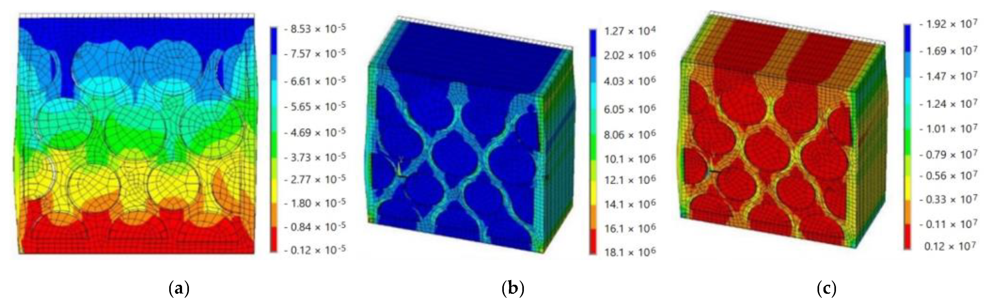
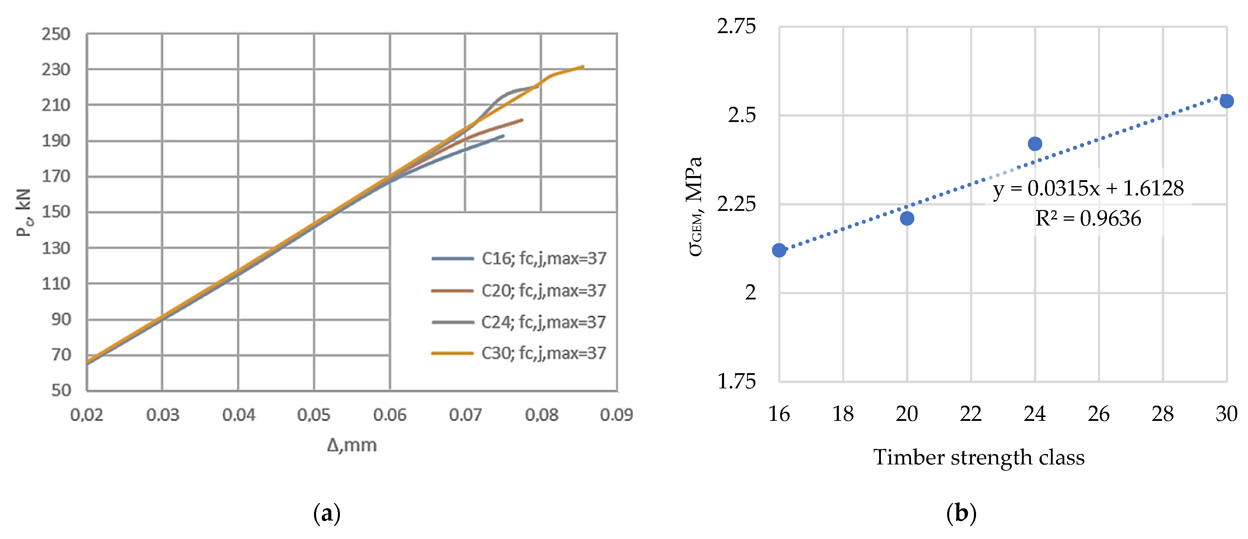
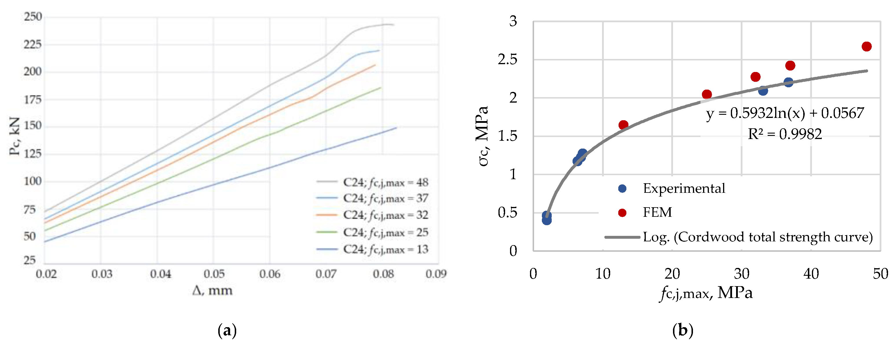
3.4. Results of FEM Modelling

The main objective of the developed calculation model was to verify the behaviour of the laboratory model C-1 under load. The compressive test was carried out with the following loads. The disruptive load acting on the upper plane of the specimen until collapse was found to be 196.13 kN. On the other hand, in the FEM calculation model, the failure of the specimen was found to be 220.22 kN, which is 12.3% more than the experimental load. Therefore, it can be concluded that the model developed is relatively accurate, and its performance is analogous to the processes observed experimentally. The resulting inaccuracy is due to the FEM model being given ideal conditions, e.g., all contact surfaces with the same properties, the head restraints are given as regular cylinders, the mortar structure is ideal, etc.
One of the main reasons for the collapse of the samples is the initial shrinkage cracks in the mortar structure and the early appearance of permeation cracks during the specimen loading. By comparing the crack orientation and frequency between the specimen tested in the laboratory and the loaded numerical FEM model, the computer program shows similarities, revealing the areas where most of the cracks are concentrated. The distribution of cracks in the sample and their comparison are shown in Figure 11a. As shown in the figure, the cracks with a maximum opening are concentrated along the edges of the samples, where loading also results in the first loss of the load-bearing capacity as the lateral planes separate. The next deformations that occur when the specimens are loaded bulge outwards the round wood billets of the concrete structure, so that only the centre of the specimen serves as the main load-bearing part.
During specimen loading, deformation processes and displacements between them are continuously developing. As the specimens are loaded in the upper plane, it is expected that this is where the greatest displacements are. The total displacements developed and the specimens’ deformed shapes are shown in Figure 11b and Figure 12a. Examining the cumulative distribution of the resulting displacements in the specimens, it can be concluded that the larger displacements, up to 0.101 mm, are observed along the lateral. The main direction where large displacements develop is in the Y-axis direction, which directly coincides with the load application direction. In this direction, the maximum displacements in the sample are 0.085 mm.
Normal voltages develop and change continuously as the sample is loaded. As the load increases, the stresses increase until failure occurs. The design model developed can demonstrate the distribution of the total normal stresses in the specimen (see Figure 12b). According to the FEM calculations in the sample, one local area, the concentrator, develops 18.1 MPa under the collapse of compressive stresses. As seen in the figure, the highest stresses are concentrated along the edges of the specimen and in the middle of the mortar and grout contact zones. If we consider the stress distribution under load along the Y-axis, it can be observed that the specimen is mainly working under compression, with only the edges developing small tensile stresses. The maximum compressive stresses in the Y-axis direction are 19.2 MPa and tensile—1.2 MPa. See Figure 12c for a detailed breakdown.
The specimen tested in the laboratory achieved the average compressive stress of 2.20 MPa. By examining the distribution of the total stresses in the specimen (Figure 12b), it can be seen that the middle of the specimen develops compressive stresses ranging from 0.0127 to 4.03 MPa. If one looks visually at the proportion of stresses in the middle, the average value could be around 2.0 MPa.
The analysis of the results obtained from the FEM model shows that the numerical calculation model behaves practically analogously to the laboratory cordwood model. For this reason, it is possible to create virtual cordwood samples in a computer program ANSYS, where the physicomechanical properties of the materials will be modified to determine the effect of the materials on the overall compressive strength of cordwood. The results of these operations are the determination of the undermining behaviour of the altered specimens’ load values at a given displacement, which are then compared with the values of the originally modelled maximum applied force of the modelled specimen to determine the variation of the compressive stresses of cordwood with the material properties. Initially, the mechanical properties of the wood are modified while maintaining the specified mortar properties. This experiment allows the wood’s influence on cordwood’s overall properties to be determined. The initial mechanical properties of the wood properties were taken from EN338 for the strength classes from C16 to C30. The FEM-produced experimental cordwood specimens are loaded under the same conditions as the original model. Virtual testing of the fabricated samples showed that as the wood strength class increases, the breaking force at which the specimen collapses increases. The displacements occurring in the specimen as a function of the applied load also increase. This relationship is illustrated in Figure 13a. As seen from the diagram, the force/deformation curves of all the tested samples overlap, which indicates that, depending on the wood material used, the deformation processes in the sample do not change significantly. Only their maximum values increase accordingly.
Variations of the compressive strength of cordwood with the wood material used can be seen in Figure 13b. As can be seen, this relationship is linear and increasing.
The influence of the mortar’s compressive strength on the behaviour of cordwood is shown in Figure 14. Cordwood specimens with compressive strengths of the mortar equal to 13, 25, 32, 37 and 48 MPa were modelled by the FEM. The influence of the mortar compressive strength on the behaviour of cordwood is shown in Figure 14.
After determining the breaking force of the modelled cordwood specimens, the average compressive stress values were determined. As seen from the data processing, keeping the wood material properties constant and modifying the mortar used resulted in compressive strengths from 13 MPa to 48 MPa—an overall increase in cordwood strength from 1.64 MPa to 2.67 MPa, which is an increase of 62.8%. On the other hand, when comparing the compressive strength of the used mortar’s strength ratio of 13 MPa and 48 MPa, a 3.7-fold increase was observed. As can be seen, the overall masonry compressive strength does not increase by a factor of 3.7 but by a factor of 1.7, which is a direct indication that the use of higher mortar compressive strength does not result in a corresponding increase in the specimen overall strength.
If we compare the experimental results with the FEM results (Figure 14b), we can see that increasing the mortar strength does not increase the overall strength of the specimen. Originally, it was predicted that the higher compressive strength mortar would significantly exceed the compressive strength of the specimens. However, the development of the FEM calculation model showed that there was no rapid increase in cordwood’s compressive strength, increasing the mortar’s mechanical properties.

4. Conclusions

The possibility of using cordwood as a structural material for the axially compressed load-carrying members in the case of fire action was stated and checked analytically. The analytical design methods for axially compressed cordwood members, including the case of fire action, were generalised, and numerical examples of its application were presented. The behaviour of the cordwood specimens depends on the mechanical properties of the such components as wood billets and mortar were used in laboratory experiments using the finite element method. The following main results were obtained:
  • The most rational and economical cordwood solution involves using a low- or medium-high-strength mortar (up to 10 MPa). The use of higher strength mortar does not significantly increase the strength of cordwood. It was proven experimentally that the use of mortars with compressive strengths of 36.76, 7.12 and 1.94 MPa for producing cordwood specimens enables obtaining a compression strength of cordwood of 2.14, 1.22 and 0.43 MPa, respectively. The increase in the wood billets’ strength class did not significantly influence the compressive strength of cordwood. Therefore, increasing the strength class of wood billets from C16 to C30 increased the compressive strength of cordwood to 21% only when the lime mortar with a compressive strength of 7.12 MPa was used. By using a cordwood wall with a thickness of 40 cm, which corresponds to the most commonly used cordwood wall thickness, it is possible to obtain load-bearing walls for two-storey buildings that provide very high fire resistance—R180, in the case of double-sided fire resistance.

Author Contributions

Conceptualization, A.B., D.S., M.G., K.B.-V. and N.I.V.; methodology, A.B. and D.S.; software, A.B.; validation, A.B.; formal analysis, A.B., M.G. and N.I.V.; investigation, A.B. and V.G.; resources, M.G.; data curation, D.S., M.G., K.B.-V., V.G. and A.P.; writing—original draft preparation, D.S., K.B.-V. and V.G.; writing—review and editing, D.S., M.G., K.B.-V., V.G., N.I.V. and A.P.; visualization, A.B., K.B.-V., V.G. and A.P.; supervision, D.S., M.G. and N.I.V.; project administration, D.S..; funding acquisition, D.S. All authors have read and agreed to the published version of the manuscript.

Funding

This research was supported by the Latvian Council of Science funded project ‘Method of correlation of coaxial accelerations in 6-D space for quality assessment of structural joints (COACCEL)’ (Nr. lzp-2020/1-0240).

Data Availability Statement

Not applicable.

Conflicts of Interest

The authors declare no conflict of interest.

References

  1. Švajlenka, J.; Kozlovská, M. Factors Influencing the Sustainability of Wood-Based Constructions’ Use from the Perspective of Users. Sustainability 2021, 13, 12950. [Google Scholar] [CrossRef]
  2. Roy, R. Cordwood Building: A Comprehensive Guide to the State of the Art—Fully Revised Second Edition; Fully Revised 2nd Edition; New Society Publishers: La Vergne, TN, USA, 2016; ISBN 9780865718289. [Google Scholar]
  3. Morin, B.; Ahmadi, M.; Rector, L.; Allen, G. Development of an Integrated Duty Cycle Test Method to Assess Cordwood Stove Performance. J. Air Waste Manag. Assoc. 2022, 72, 629–646. [Google Scholar] [CrossRef] [PubMed]
  4. Buka-Vaivade, K.; Serdjuks, D.; Pakrastins, L. Cost Factor Analysis for Timber–Concrete Composite with a Lightweight Plywood Rib Floor Panel. Buildings 2022, 12, 761. [Google Scholar] [CrossRef]
  5. Sultana, R.; Rashedi, A.; Khanam, T.; Jeong, B.; Hosseinzadeh-Bandbafha, H.; Hussain, M. Life Cycle Environmental Sustainability and Energy Assessment of Timber Wall Construction: A Comprehensive Overview. Sustainability 2022, 14, 4161. [Google Scholar] [CrossRef]
  6. Poranek, N.; Łaźniewska-Piekarczyk, B.; Czajkowski, A.; Pikoń, K. MSWIBA Formation and Geopolymerisation to Meet the United Nations Sustainable Development Goals (SDGs) and Climate Mitigation. Buildings 2022, 12, 1083. [Google Scholar] [CrossRef]
  7. Gravit, M.; Serdjuks, D.; Bardin, A.; Prusakov, V.; Buka-Vaivade, K. Fire Design Methods for Structures with Timber Framework. Mag. Civ. Eng. 2019, 85, 92–106. [Google Scholar] [CrossRef]
  8. Nicholls, D.; Miles, T. Cordwood Energy Systems for Community Heating in Alaska—An Overview; General Technical Report PNW-GTR-783; U.S. Department of Agriculture, Forest Service, Pacific Northwest Research Station: Portland, OR, USA, 2009; Volume 783, 17p. [CrossRef]
  9. Nanni, A.; Venturi, M.; Paiter, L. Permaculture MESMIS—A Methodology to Evaluate Ecological Well-Being on Permaculture Farms. Int. Res. J. Biol. Sci. 2021, 10, 47–57. [Google Scholar]
  10. Morel, K.; Léger, F.; Ferguson, R. Permaculture. Encycl. Ecol. 2018, 4, 559–567. [Google Scholar]
  11. Szewczyk, J. Cordwood Heritage; Bialystok Technical University: Bialystok, Poland, 2007; p. 128. ISBN 978995528. [Google Scholar]
  12. McCann, R.; Thomas, B. Permaculture; Utah State University: Logan, UT, USA, 2013. [Google Scholar]
  13. Flatau, R.; Flatau, B. Cordwood and Community. Back Home Magazine, Jan/Feb 2010. 41–43.
  14. Hagman, O. A Technology in Permanent Transition: 200 Years of Cordwood Building with Consumers as Producers. ICON 2012, 18, 142–156. [Google Scholar]
  15. Mouterde, R.; Morel, J.-C.; Martinet, V.; Sallet, F. The Mechanical Performance of Cordwood. Biosyst. Eng. 2011, 108, 237–243. [Google Scholar] [CrossRef]
  16. Yanfeng, T.; Ping, W.-J. The Research of Development Framework for Workflow Based on Cordwood Structure. In Proceedings of the 2013 6th International Conference on Intelligent Networks and Intelligent Systems (ICINIS), Shenyang, China, 1–3 November 2013; pp. 17–20. [Google Scholar] [CrossRef]
  17. Gravit, M.; Shabunina, D.; Antonov, S.; Danilov, A. Thermal Characteristics of Fireproof Plaster Compositions in Exposure to Various Regimes of Fire. Buildings 2022, 12, 630. [Google Scholar] [CrossRef]
  18. Gravit, M.; Simonenko, Y.; Larionov, A. Method Single Burning Item (SBI) for Fire Hazard of Wood Constructions. E3S Web Conf. 2019, 91, 02049. [Google Scholar] [CrossRef]
  19. Korolkov, D.; Gravit, M.; Aleksandrovskiy, M. Estimation of the Residual Resource of Wooden Structures by Changing Geometric Parameters of the Cross-Section. E3S Web Conf. 2021, 244, 04010. [Google Scholar] [CrossRef]
  20. Gaile, L.; Pakrastins, L.; Ratnika, L. Structural Health Monitoring by Merging Dynamic Response Data. Mag. Civ. Eng. 2022, 111, 11111. [Google Scholar] [CrossRef]
  21. Gaile, L.; Ratnika, L.; Pakrastins, L. RC Medium-Rise Building Damage Sensitivity with SSI Effect. Materials 2022, 15, 1653. [Google Scholar] [CrossRef] [PubMed]
  22. Brics, A. Behaviours Analysis of Load-Carrying Members of Cordwood Houses; Riga Technical University: Riga, Latvia, 2019. [Google Scholar]
  23. EN 1996-1-1:2005+A1:2012; Eurocode 6—Design of Masonry Structures—Part 1-1: General Rules for Reinforced and Unreinforced Masonry Structures. iTeh Inc.: Newark, DE, USA, 2005. Available online: https://standards.iteh.ai/catalog/standards/cen/502c057e-25f1-4228-a10a-635c4aa9efd4/en-1996-1-1-2005a1-2012 (accessed on 25 August 2022).
  24. EN 1995-1-2:2004; Eurocode 5: Design of Timber Structures—Part 1-2: General— Structural Fire Design. iTeh Inc.: Newark, DE, USA, 2004. Available online: https://standards.iteh.ai/catalog/standards/cen/7c5128eb-3949-494d-abe5-f1832864cb15/en-1995-1-2-2004 (accessed on 2 September 2022).
  25. EN 1992-1-2:2004/A1:2019; Eurocode 2: Design of Concrete Structures—Part 1-2: General Rules—Structural Fire Design. iTeh Inc.: Newark, DE, USA, 2019. Available online: https://standards.iteh.ai/catalog/standards/cen/651bc53c-16d5-4983-bc4f-be403472ee95/en-1992-1-2-2004-a1-2019 (accessed on 2 September 2022).
  26. Incropera, F.P.; Incropera, F.P. (Eds.) Fundamentals of Heat and Mass Transfer, 6th ed.; John Wiley: Hoboken, NJ, USA, 2007; ISBN 9780471457282. [Google Scholar]
  27. Harrington, J.; Jacobson, M.; Short, C. Handbook on Structural Timber Design to Eurocode 5 (IS EN 1995-1-1) Rules Including Strength Capacity Tables for Structural Elements; COFORD: Dublin, Ireland, 2006; ISBN 9781902696522. [Google Scholar]
  28. EN 1991-1-2:2002/AC:2013; Eurocode 1: Actions on Structures—Part 1-2: General Actions—Actions on Structures Exposed to Fire. iTeh Inc.: Newark, DE, USA, 2002. Available online: https://standards.iteh.ai/catalog/standards/cen/6499fb76-e1b3-4837-98a9-ff338860a4f9/en-1991-1-2-2002-ac-2013 (accessed on 2 September 2022).
  29. EN 1996-1-2:2005; Eurocode 6—Design of Masonry Structures—Part 1-2: General Rules—Structural Fire Design. iTeh Inc.: Newark, DE, USA, 2005. Available online: https://standards.iteh.ai/catalog/standards/cen/ab1c6dc8-e5f0-4c77-ae93-521b41d4b81a/en-1996-1-2-2005 (accessed on 2 September 2022).
  30. EN 338:2016; Structural Timber—Strength Classes. iTeh Inc.: Newark, DE, USA, 2016. Available online: https://standards.iteh.ai/catalog/standards/cen/492c108d-268a-4cbd-9b59-3f31792887c5/en-338-2016 (accessed on 25 August 2022).
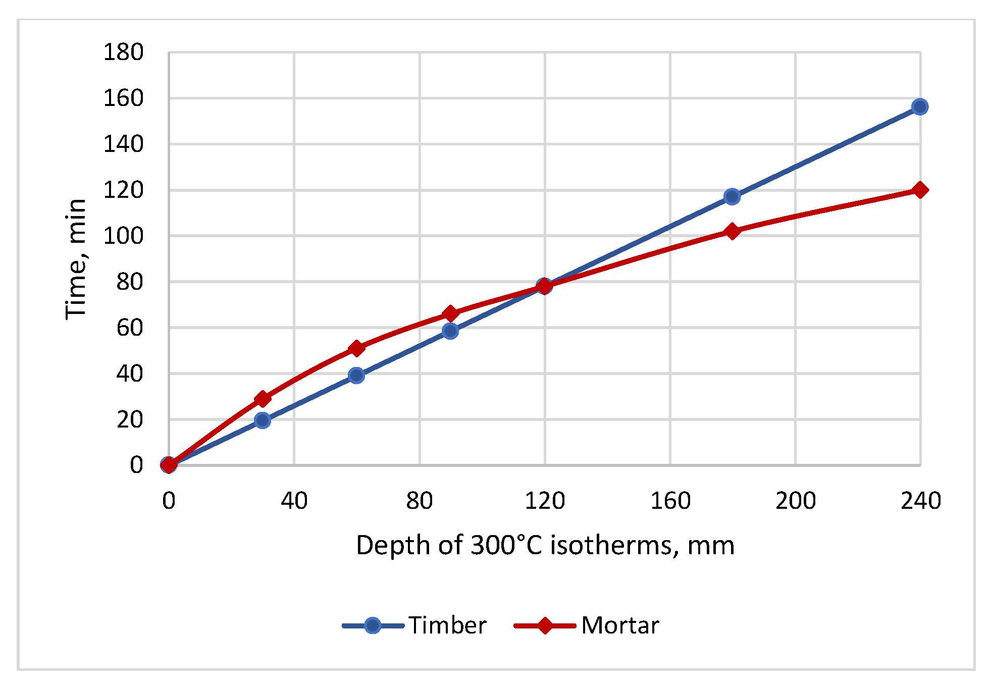
Figure 1. (a) Pedestrian bridge with wood logs in Rodini Park, Rhodes; (b) cordwood specimens considered in the current study.
Buildings 12 01702 g001
Figure 2. Scheme of the cordwood layers.
Buildings 12 01702 g002
Figure 3. Depth of 300 °C isotherms for timber and concrete wall.
Buildings 12 01702 g003
Figure 4. Laboratory specimens with the different types of mortars: (a,b) lime mortar; (c) clay; (d) cement mortar.
Buildings 12 01702 g004
Figure 5. Designations of laboratory specimens.
Buildings 12 01702 g005
Figure 6. Specimen C-1 (a) and its FEM model (b).
Buildings 12 01702 g006
Figure 7. Applied boundary conditions (a) and development of contact surfaces between the wood and mortar (b).
Buildings 12 01702 g007
Figure 8. The design scheme of the considered fragment of the cordwood wall.
Buildings 12 01702 g008
Figure 9. Laboratory tests for cordwood components: (a) testing of wood billets; (b) testing of clay and mortar cubes.
Buildings 12 01702 g009
Figure 10. Result of cordwood specimens testing: (a) placement of the cordwood specimen in the testing machine; (b) mean compressive strength of cordwood as a function of the maximum compressive strength of the used mortar.
Buildings 12 01702 g010
Figure 11. The behaviour of the cordwood specimen C-1, obtained by the FEM model: (a) development of the crack in the course of loading; (b) total displacements of cordwood specimen under the action of maximum compression force.
Buildings 12 01702 g011
Figure 12. The behaviour of the cordwood specimen C-1, obtained by the FEM model: (a) displacements of cordwood specimen under the action of maximum compression force in the direction of the Y-axis; (b) distribution of resulting normal stresses in the cordwood specimen under the applied maximum axial force; (c) distribution of resulting normal stresses in the cordwood specimen in the direction of Y-axis under the applied maximum axial force.
Buildings 12 01702 g012
Figure 13. Influence of the wood strength classes on the behaviour of cordwood: (a) force/deformation curves for the cordwood specimen differed with the wood strength classes; (b) compressive strength of cordwood as a function of the strength classes of the wood.
Buildings 12 01702 g013
Figure 14. Influence of the mortar compressive strength on the behaviour of cordwood: (a) force/deformation curves for the cordwood specimen differed with the mortar compressive strength; (b) compressive strength of cordwood as a function of the compressive strength of mortar.
Buildings 12 01702 g014
Table 1. Depth of 300 °C isotherms for timber and mortar wall in case of one-sided fire.
Time t, minCharring Depth dchar,0, mmDepth of 300 °C Isotherms in Mortar, mmReduction in Wall Cross-Section, mm
3019.52936
6039.05157
9058.56673
120787885
180117102124
240156120163
Table 2. Depth of 300 °C isotherms for timber and mortar wall in case of double-sided fire for walls with thicknesses b equal to 200 mm, 300 mm and 400 mm and more.
Time t, minCharring Depth dchar,0Depth of 300 °C Isotherms in Mortar, mm/Reduction in Wall Cross-Section, mm
b = 200 mm b = 300 mm b ≥ 400 mm wall
3019.529/7229/7229/72
6039.051/11651/11651/116
9058.569/15266/14666/146
12078-/-81/17678/170
180117-/-116/248105/248
240156-/--/-123/326
Publisher’s Note: MDPI stays neutral with regard to jurisdictional claims in published maps and institutional affiliations.

