Article

Seismic Performance and Design of the Fully Assembled Precast Concrete Frame with Buckling-Restrained Braces

1
College of Civil Engineering, Hunan University, Changsha 410082, China
2
Hunan Provincial Key Laboratory on Damage Diagnosis for Engineering Structures, College of Civil Engineering, Hunan University, Changsha 410082, China
*
Author to whom correspondence should be addressed.
Buildings 2022, 12(11), 1818; https://doi.org/10.3390/buildings12111818
Submission received: 9 September 2022 / Revised: 7 October 2022 / Accepted: 14 October 2022 / Published: 31 October 2022
(This article belongs to the Special Issue Reinforced Concrete Buildings)

Abstract

:
Although precast concrete structures have been widely used in building engineering, their application in moderate- and high-seismic zones is restricted because of poor lateral performance. This study proposed a fully assembled precast concrete frame with buckling-restrained braces (PCF-BRB) to simplify construction and enhance seismic performance. A nonlinear finite element model of the PCF-BRB was established using ETABS to investigate the feasibility of its use in seismic regions. The accuracy and rationality of the analysis model were verified by existing experimental data. Furthermore, the seismic performance, including plastic hinge development, internal force distribution, maximum inter-story drift, and energy dissipation, of the PCF-BRB was evaluated through static pushover analysis and dynamic time history analysis. The analysis results showed that the PCF-BRB has good seismic performance. Finally, this study provided a recommended seismic performance factor for design, namely the stiffness ratio of buckling-restrained braces (BRBs) to the frame (k, defined later) for the PCF-BRB structure. It is recommended that the stiffness ratio range of low-rise PCF-BRB structures should be 1.5 ≤ k ≤ 3.0, and that of high-rise PCF-BRB structures should be 3.0 ≤ k ≤ 4.0.

1. Introduction and Background

During the past few decades, precast concrete structures have been widely used in building engineering because they have the advantage of labor-saving, construction efficiency, and energy conservation. However, the poor lateral performance of precast concrete structures limits its application in moderate- and high-seismic zones. In traditional frame structures, steel braces are installed to improve the structure’s seismic performance. The braces have a relatively high axial stiffness and are used to bear the lateral forces on the braced frame, which can not only strengthen and reinforce the building but also dissipate the seismic energy. Thus, the precast concrete frame with steel braces (PCF-B) structure gives full play to the advantages of rapid construction and meets the seismic requirements. The system divides the structure into two parts: gravity frame and braced frame. It reduces rigid beam-column joints, improving construction efficiency and seismic performance.
The traditional steel braces have an obvious disadvantage, that is, the compressive performance is inferior to the tensile performance, which leads to quick buckling when the structure bears a seismic or wind load, making the hysteresis curve pinching and the seismic performance unstable [1]. The buckling problem can be effectively solved if they are transformed into BRBs by providing constraints on the outside or inside of the braces, resulting in stable hysteretic performance and higher energy dissipation capacity under a cyclic load [2]. Figure 1 shows the constitution of typical BRBs. BRBs consist of three parts: core steel plate, buckling restraint tube, and unbonded layer, among which the core steel plate is divided into yield, transition, and junction sections. Due to the constraint of the buckling restraint tube, BRBs do not produce buckling. The hysteretic performance of BRBs under cyclic loading is stable, which has obvious advantages over ordinary steel braces. Studies have shown that BRBs can effectively enhance the structure’s stiffness, strength, and seismic performance [3,4,5]. On this basis, a fully assembled precast concrete frame with buckling-restrained braces (PCF-BRB) was proposed in this study to simplify construction and enhance seismic performance.
There are many differences between prefabricated and traditional buildings, such as connections, structural integrity, robustness, etc. Many researchers have paid more attention to the details of prefabricated structures. Aksoylu et al. [6] found that snow loads may cause catastrophic damage to prefabricated industrial buildings. They investigated the reasons for these damages in detail. Gemi et al. [7] found that the thinned regions of the purlins are responsible for the structure’s failure since shear cracks usually initiate at these regions. Özkılıç et al. [8] improved the shear capacity of the purlins by using steel fiber-reinforced concrete without changing the cross-section geometry and reinforcement and undertook experimental and numerical studies.
Using BRBs in frames for lateral force resistance can solve many practical and economic problems and offer significant advantages over conventional braced and moment-resisting frames [9]. Yakhchalian et al. [10] demonstrated that a properly constructed steel BRB frame could withstand severe seismic energy and maintain full bearing capacity and provided an advanced intensity measure for residual drift assessment of steel BRB frames. Zhou et al. [11] and Macrae et al. [12] improved the application and design methods of BRBS in steel frames. Özkılıç [13] investigated the interaction of flange and web slenderness ratio and overstrength factor to improve the behavior of long links, then utilized rupture index values to verify proposed stiffener configurations further. Özkılıç et al. [14] proposed a novel detachable, replaceable link that employed a splice connection at the mid-length of the link for eccentrically braced frames.
In reinforced concrete frames, the application of BRBs not only enhances the structural strength, stiffness, and energy dissipation capacity but also reduces the size of the reinforced concrete members, thereby reducing the building weight and the maximum drift during severe earthquakes [15]. Bai et al. [16] proved, through simulation, that BRBs improved the strength and ductility of concrete frames, while synergistic interaction could not be ignored in the design. Guerrero et al. [17] showed, through a case study example, that BRBs were a great alternative to prevent damage or even collapse. Oviedo-Amezquita et al. [18] introduced and developed acceptance criteria and damage index for BRBs. Guerrero et al. [19] conducted experiments to study the effects of BRB application on concrete structures. Ruiz et al. [20] proved that the rehabilitation system based on the inclusion of BRBs in the first soft story presented a structural fragility very similar to that corresponding to a traditional rehabilitation system based on concrete jacketing of columns in the first story. Ghazal et al. [21] concluded that retrofitting the bridge with BRBs is an effective mitigation measure to increase lateral strength. Cao et al. [22] experimentally analyzed the assembled bolt-connected BRBs with a pair of thin-walled concrete-infilled steel shells. Bashiri et al. [23] conducted a numerical and experimental investigation on a BRB confined with partially carbon fiber-reinforced polymer. Al-Sadoon et al. [24] experimentally tested and modeled a replaceable fuse BRB.
Özkılıç [25] conducted numerical analyses using ABAQUS to investigate the effects of the initial imperfection of the steel core, gap size (1–5 mm), and friction coefficient (0.01–0.5) between the encasing and steel core on the behavior of BRBs. Steel eccentric braces have high ductility, a stable and reliable yielding mechanism, and architectural versatility as well [26]. Özkılıç et al. [27] undertook a numerical study to evaluate seismic response factors for steel buckling-restrained braced frames using the FEMA P695 methodology.
Currently, the existing research is mainly focused on the traditional concrete frame with BRBs and the steel frame with BRBs and lacks research on the seismic performance of the fully precast concrete frame with BRBs. At the same time, due to the lateral force, they are mainly resisted by braces in PCF-BRB structures. The recommended range of the stiffness ratio is different from the prior research, which causes inconvenience for engineering designers to use the lateral stiffness ratio-based seismic structure design method (defined later). Thus, in this study, the nonlinear finite element software ETABS was used to establish 4- and 12-story PCF-BRB structure analysis models, verified by existing experimental data to ensure the reliability of subsequent analysis results. A recommended seismic performance factor (k), namely the lateral stiffness ratio of the BRBs to the frame, was introduced to reflect their matching and is expressed as Equation (1) [28]. Different stiffness ratio k values were selected. The influence of k values on the structure’s seismic performance, including plastic hinge development, base shear-vertex displacement curve, maximum inter-story drift, and brace energy dissipation ratio, were explored through static pushover analysis and dynamic time history analysis. Based on the analysis results, the suggested range of k was determined.
k = K B R B K F
where KBRB is the lateral stiffness of BRBs and KF is the lateral stiffness of the frame. The lateral stiffness of frame columns can be simply calculated by the modified contraflexure point method (expressed as Equation (2) [29]) and then added up to get KF. Once KF and k are confirmed, KBRB can be calculated and used to design BRBs.
D = α 12 i h 2
where D is the lateral stiffness of the frame column; α is the stiffness-modified factor relating to the line stiffness of frame columns and beams; i is the line stiffness of the frame column, and h is the height of the frame column. This is a shear force distribution method considering joint rotation.

2. Modeling and Verification

2.1. Modeling

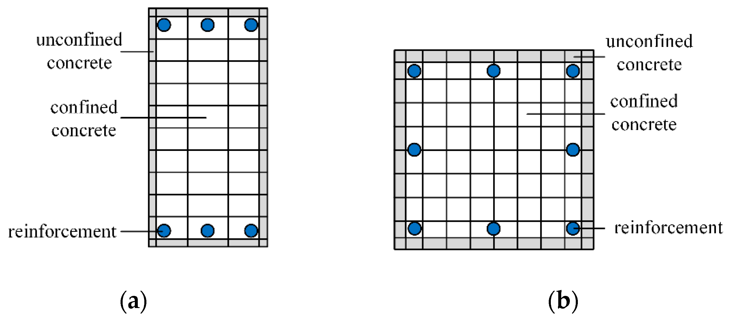
The beam and column components were simulated by the fiber-beam elements. To accurately consider the influence of axial force variation on the bending capacity of frame beams and columns, it was necessary to divide the component section, as shown in Figure 2. Except for the rigid zone, we set fiber hinges in fiber-beam elements, and the type was Fiber P-M2-M3 [30]. The corresponding material-constitutive relation could be set for each fiber, and the deformation and force of the cross-section could be obtained by integrating each fiber [30]. The bilinear model was used for the reinforcement stress-strain relationship, as shown in Figure 3a, in which εy is the yield strain, fy is the yield stress, εu is the ultimate strain, fu is the ultimate stress, E0 is the initial stiffness, and E’ is the hardening stiffness. The kinematic hardening hysteresis rule was used to consider the Bauschinger effect [31]. Since the constraint effect of the stirrups on concrete cannot be directly considered in ETABS, the compressive stress-strain relationship in the core area of concrete should be determined by the Mander model [32] according to the form of the stirrups, as shown in Figure 3b. The Takeda hysteresis rule was used [31]. εco is the peak compressive strain of unconfined concrete, f c o ' is the peak compressive strength of unconfined concrete, εcc is the peak compressive strain of confined concrete, f c c ' is the peak compressive strength of confined concrete, εucu and εcu are the ultimate compressive strain of unconfined and confined concrete. The compressive parameter calculation is shown in Equations (3)–(8). The bilinear model was used for the tensile concrete stress-strain relationship, as shown in Figure 3c, in which εcr is the cracking strain, fct is the axial tensile strength, and εmax is the maximum tensile strain. The tensile parameter calculation is shown as Equation (9) [33].
σ c = f c c ' x r r 1 + x r
x = ε c ε c c
r = E c E c E s e c
f c c ' = f c o ' ( 2.254 1 + 7.94 p f c o ' 1.254 2 p f c o ' )
ε c c = ε c o [ 1 + 5 ( f c c ' f c o ' 1 ) ]
ε c u = 0.004 + 1.4 ε s u ρ f y f c c
where f c c ' is the peak compressive strength of confined concrete; εcc is the peak compressive strain of confined concrete; f c o ' is the peak compressive strength of unconfined concrete; εco is the peak compressive strain of unconfined concrete; Ec is the tangent modulus of unconfined concrete; Esec is the secant modulus at f c c ' ; p is the lateral effective restraint stress; εcu is the ultimate compressive strain of confined concrete; εsu is tensile failure strain of the stirrup; ρ’ is the volume reinforcement ratio of the stirrup, and fy is the yield strength of the stirrup.
f c t = 0.395 f c u 0.55
where fct is the axial tensile strength of concrete and fcu is the cube compressive strength of concrete.
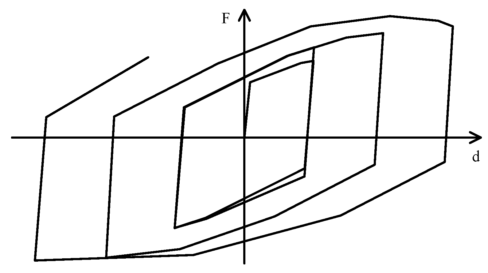
BRBs were simulated using the multilinear plastic link elements with the BRB hardening rule [31] to simultaneously consider the kinematic and isotropic hardening effects. The effect of the friction coefficient has been included in the definition of the load-displacement relationship of the link [34]. Because the BRBs only yield and do not buckle, they will not fail until close to tensile rupture, according to available test information [35,36,37,38]. The force-displacement skeleton curve was bilinear, as shown in Figure 4. The definition of the BRB hardening hysteresis rule includes four parameters: hardening factor, maximum plastic deformation at full hardening, accumulated plastic deformation at full hardening, and proportion of accumulated plastic deformation. The hardening factor is the strain hardening coefficient of the inner core steel plate, whose value is the ratio of maximum stress to yield stress. The maximum plastic deformation and accumulated plastic deformation at full hardening is the test’s maximum and accumulated plastic deformation. The proportion of accumulated plastic deformation was set to zero [31]. When establishing the finite element model of the braced frame, the gusset plate area was set as the rigid zone, and the thick blue line part is represented as the rigid zone in Figure 5.

2.2. Verification

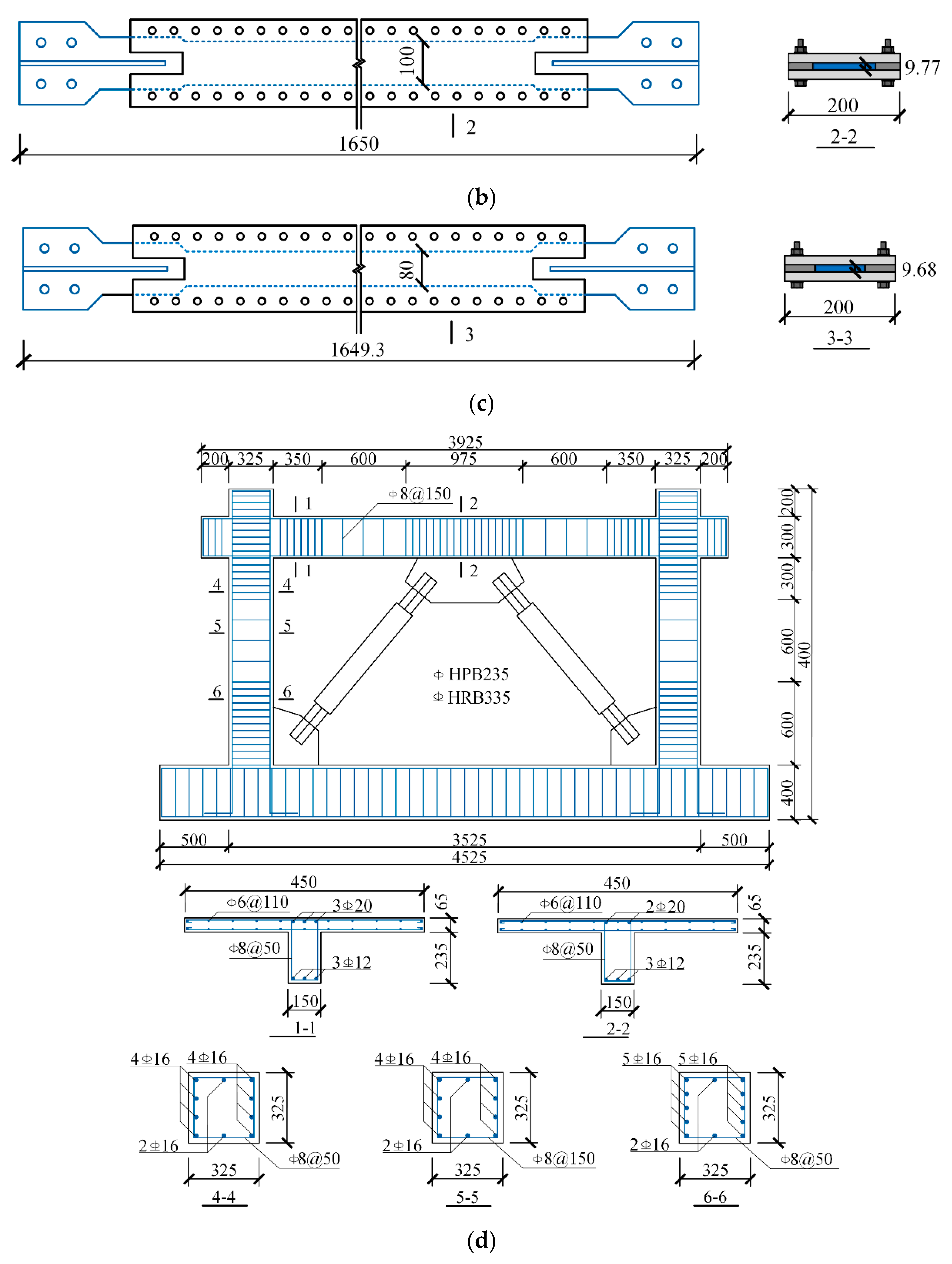
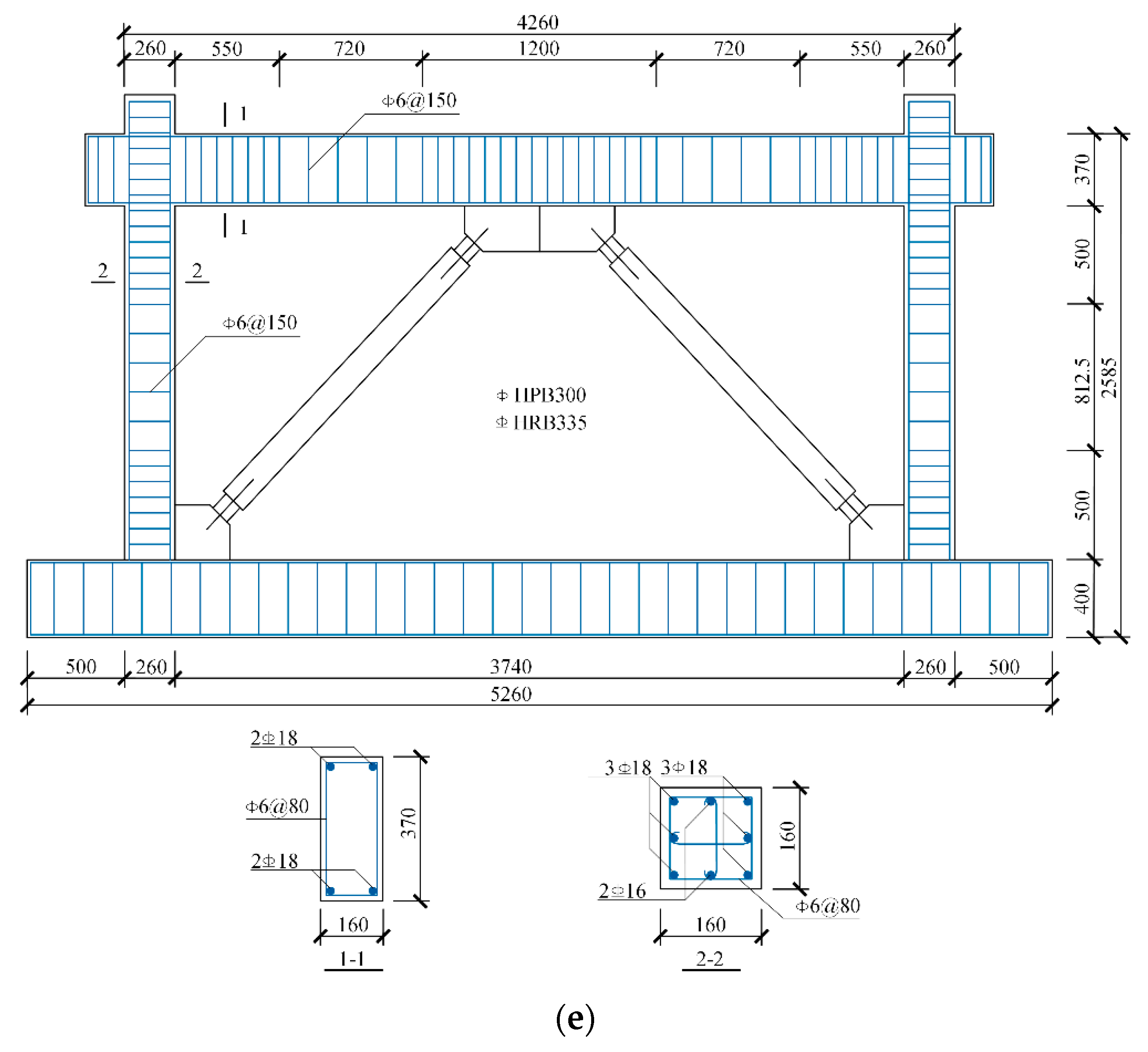
Existing experimental specimens, including BLY225-1 [35], V1 [36], V2 [36], BRBCF3 [37], BRBF3 [38], and BRBF5 [38], were selected to verify the rationality of the finite element model, as shown in Figure 6. The section of specimen BLY225-1 was a 55 × 296 mm cruciform steel plate using BLY225 low-yield steel. Specimens BRBCF3, BRBF3, and BRBF5 were 1-story buckling-restrained braced concrete frame substructures. The BRB specimen test information is shown in Table 1. The input multilinear force-displacement relation parameters, shown in Table 2, were used to define yield points and ultimate points of bilinear relation. The input BRB hardening parameters are listed in Table 3. The substructure specimen test information is shown in Table 4. The input multilinear force-displacement relation parameters of BRBs are shown in Table 5, and the input BRB hardening parameters are listed in Table 6. During specimen verification, the restraint of joints was hinged (UX, UY, UZ restrained), and displacement loading was applied on one joint. In substructure verification, fixed supports (UX, UY, UZ, RX, RY, RZ restrained) were arranged at the bottom. The substructures were modeled in the X-Z plane. All the nodes of the substructure were set as rigid connections, including the connections of frame beams, columns, and BRBs. One of the top beam-column joints was arranged as just UX restrained and applied the displacement loading in the X direction. The other beam-column and beam-brace joints were free.
In BRBCF3, the size of the beam elements was 0.17 m, and that of the column elements was 0.15 m, except for the rigid zone. In the rigid zones, the size of the elements was that of the zones. In BRBF3 and BRBF5, the size of the beam elements was 0.18 m, and that of the column elements was 0.125 or 0.135 m, except for the rigid zone. The element size selected as the height of frame beams and columns ensured the stability of the results [30]. In this study, the element size was approximately half the height of the frame beams and columns. ETABS automatically divided fibers according to the cross-section characteristics of the elements with specified fiber hinges. When using the Mander model, ETABS automatically distinguished between onstrained and unconstrained areas and assigned different concrete models according to the location of stirrups. Thus, in the substructure verification section, the fiber was auto-divided.
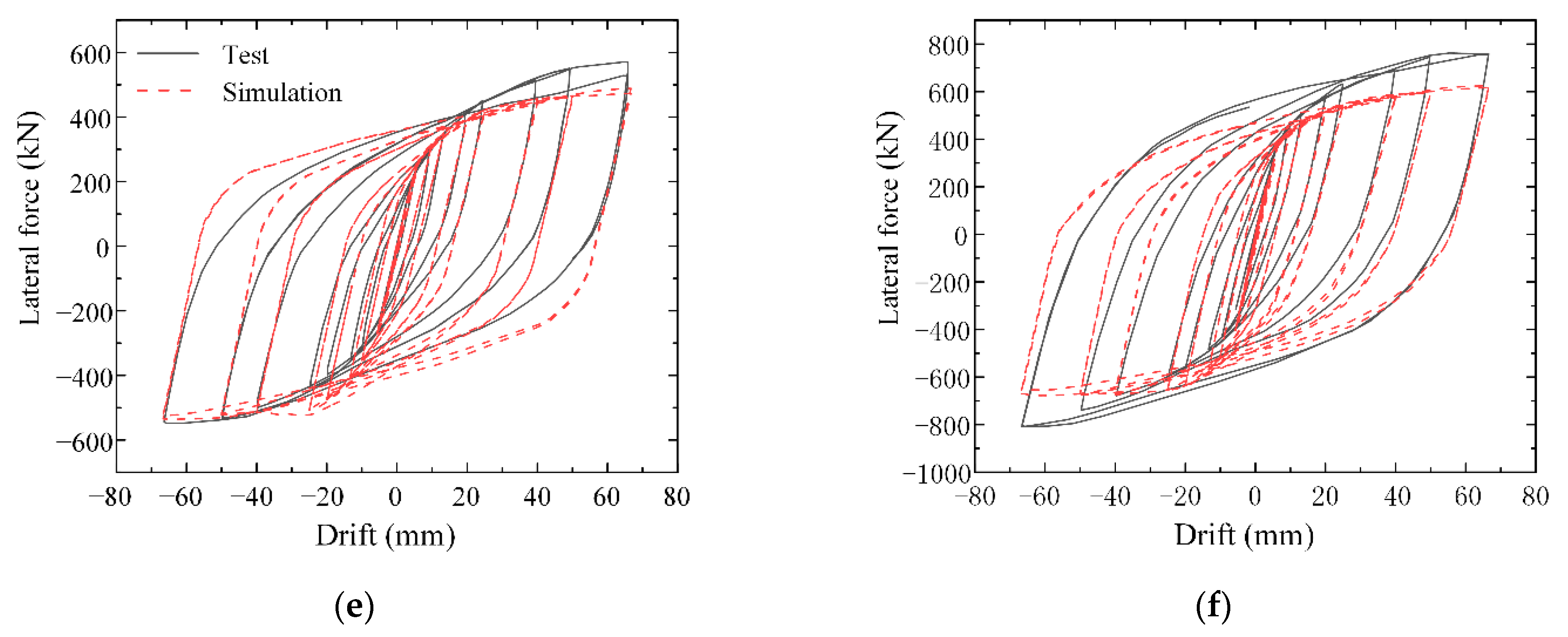
Specimens V1 and V2 were similar to the braces used in further analysis. The brace type (herringbone) of the substructures was the same as that used in further analysis. The hysteresis curve comparison between the simulation and test is shown in Figure 7. The bearing capacity and stiffness of the finite element model were well consistent with the test value in cyclic loading. The multilinear plastic connection unit and the BRB hardening hysteresis rule could effectively reflect the isotropic hysteresis effect of the BRB [39].

3. PCF-BRB Structure Design

3.1. BRB Design

The sketch diagram of BRB is shown in Figure 8, where Lj, Lt, Ly, and Lw refer to the length of the junction section, transition section, yield section, and working segment, respectively; and Aj, At, and Ay refer to the area of the junction, transition, and yield sections, respectively. Among them, the junction section area was 2.2 times the yield section area, and the transition section area was 1.6 times the yield section area. The junction section, transition section, and yield section lengths were 0.24, 0.06, and 0.7 times the BRB length, respectively [40].
BRBs were made of Q235 steel, assuming all the deformation occurred in the yield section. According to Equation (10), the inter-story drift at BRB yield could be calculated as 1/623, meeting the requirement of BRB to maintain elasticity under small seism.
θ y , B R B = ε y , B R B × 0.7 cos φ sin φ
where θy,BRB is the inter-story drift at the BRB yield; εy,BRB is the yield strain of the BRB; φ is the angle between the BRB and horizontal plane.
According to the parameters mentioned above, the BRB yield section area could be calculated by Equation (11) [40].
A c = k e f f ( L j A y A j + L t A y A j + L y ) E cos 2 φ
where keff is the effective stiffness for brace resisting lateral loading.

3.2. Structure Design

The precautionary seismic intensity of the structure example designed in this paper was 8 degrees (0.20g, g is the acceleration of gravity). The seismic design group was the first group, and the site classification was II. The structure layout is shown in Figure 9. The plane was 5 × 5 spans, each span was 6 m, and each story height was 3.3 m. The braces were arranged in the peripheral frame around the structure, forming the braced frame, and mainly bore a lateral load. The internal frame was the gravity frame and mainly bore a gravity load. The constant load of the floor and roof was 5 kN/m2, the floor’s live load was 2 kN/m2, the load of the internal beam was 4.5 kN/m, and the load of the peripheral beam was 9 kN/m. In all load cases, the P-delta effects were considered by turning on the geometric nonlinearity option. Then the equilibrium equations considered the deformed configuration of the structure. The arrangement of BRBs was selected as cross-layer X type [41] because pressure and tension could be mutually balanced in midspan, which not only ensured the seismic performance of the structure but also reduced the capacity requirement of frame beams.
To reduce the influence of the brace tension on the adjacent columns, all the joints of the peripheral frame were set as rigid connections. As for the gravity frame, the beam-column joints and the bottom of the first-floor frame columns were hinged. The articulated beam-column joints were connected by bracket bolt pins, and the rigid beam-column joints were connected by bolts, as shown in Figure 10. The failure mode of bolted beam-column joints was the same as that of cast-in-place beam-column joints [42]; thus, the PCF-BRB structure modeling method was the same as that of the cast-in-place structure. This study did not pay attention to the influence of the size of gusset plates, which were designed as unified rectangular steel plates 600 mm in length and 300 mm in width. Frame beams and columns were auto-meshed at intermediate joints and intersections with other frames and area edges. Generally, there was a beam element in each span, but if the BRB gusset plate was in the midspan, there were two beam elements. The hinges’ distance from ends was set as half the height of frame beams and columns. The relative length of the frame element at the hinges was 0.02, which was auto-set in ETABS. In frame beam sections, the core concrete fiber size was 100 mm in width and 40 mm in height. In frame column sections, the core concrete fiber size was 80–120 mm in width and height, according to the column size. Longitudinal reinforcement was simulated as single fibers [30]. We considered mesh optimization and chose appropriate simulation methods from existing research and literature [30,31,34,39,43,44,45,46].
The lateral stiffness ratio design method [28] was adopted in this paper, divided into the following steps: (1) Preliminarily design concrete frame members; (2) calculate the stiffness of each layer; (3) select the stiffness ratio k and design the BRBs; (4) design concrete frame members and reinforcement according to the code; (5) check the elastoplastic calculation result of the structure. The modified contraflexure point method [28] was used to calculate the concrete frame stiffness. Using the PKPM software to complete the structure design, all the beam dimensions of the 4 and 12 stories were 300 mm × 600 mm.
In the four-story structure, the concrete strength was C30 [33]. Its axial characteristic compressive strength was 20.1 MPa. The modulus of elasticity and Poisson’s ratio were 30,000 MPa and 0.2. The peak and ultimate compressive strain were 0.002 and 0.0072, respectively. The peak tensile strength and strain were 2.79 MPa and 0.000093, and the ultimate tensile strain capacity was 0.001024. In the 12-story structure, the concrete strength was C40 [33]. Its axial characteristic compressive strength was 26.8 MPa. The modulus of elasticity and Poisson’s ratio were 32,500 MPa and 0.2, respectively. The peak and ultimate compressive strain were 0.002 and 0.006, respectively. The peak tensile strength and strain were 3.22 MPa and 0.000099, and the ultimate tensile strain was 0.001091. The longitudinal reinforcement was HRB400 with a minimum yield strength and minimum tensile strength of 400 MPa and 540 MPa, respectively [33]. Its elastic modulus was 200,000 MPa. The stirrups were HPB300 with a minimum yield strength and minimum tensile strength of 300 MPa and 420 MPa, respectively [33]. Its elastic modulus was 210,000 MPa. The dimensions of the frame columns are shown in Table 7.
Since the overall structure is symmetric and the horizontal load could be evenly distributed on the two braced frames, a 2D model was adopted to analyze the structure in this paper. The 2D model is shown in Figure 11, and the arrangement of the braced frame was consistent with that in Figure 9b. The two gravity columns represented the two kinds of gravity frame columns in Figure 9a, respectively. And the stiffness and cross-section area of each gravity column were proportionally enlarged according to the number of each gravity column [44]. According to the load range of each gravity frame column in Figure 9a, a constant load and a live load were applied to each gravity column. Rigid diaphragms were established on each floor to simulate the horizontal constraints of floor slabs [44]. The structures were modeled in the X-Z plane. The braced frame arranged fixed supports (UX, UY, UZ, RX, RY, RZ restrained) at the bottom. The beam-column joints restrained UY, RX, RZ to avoid out-of-plane displacement. And the beam-brace joints were free. Hinged supports (UX, UY, UZ restrained) were arranged at the bottom in the gravity columns. The column joints were arranged UY, RX, RZ restrained to avoid out-of-plane displacement.
According to the Code for Seismic Design of Buildings in China (GB 50011-2010) [47], the lower limit of the 4-story and 12-story PCF-BRB structure stiffness ratio should be 1.5 and 3, respectively. It is specified that the seismic overturning moment (distributed by the stiffness) of the bottom braced frame should be greater than 50% of the total seismic overturning moment of the structure. Therefore, the k values of 4-story PCF-BRB were selected as 1.5, 2, 3, 4, 5, 6, and 7, and those of 12-story PCF-BRB were 3, 4, 5, 6, and 7.
The yield section area of BRBs with each stiffness ratio is listed in Table 8, and the overall information of the PCF-BRB structure is listed in Table 9. The yield and ultimate displacement of BRBs were 3.94 and 94 mm, respectively. The input yield and ultimate forces of BRBs are shown in Table 10 to define the bilinear relation. The hardening factor was 1.2, the maximum plastic and accumulated plastic deformations at full hardening as a ratio of yield were both 18.8 [40], and the proportion of accumulated plastic deformation was 0 [31]. Each structure model is named after modal A-B, among which A represents the number of stories, and B represents the stiffness ratio value. For example, modal4-1.5 represents the 4-story PCF-BRB structure with the k value of 1.5. The elastic inter-story drift means the inter-story drift under a frequently occurring earthquake, which is possible to occur with a 63% probability of exceedance (with a return period of 50 years), and the structure is in an elastic condition. The proportion of seismic overturning moment carried by braces corresponded to the clause in GB 50011-2010 mentioned above.
When BRBs reached yield and the maximum displacement, they were considered yielded and failed [31]. The yield and failure of frame beams and columns were considered by setting fiber hinges. When the longitudinal reinforcement of members yielded, the hinges were considered yielded [30]. When the longitudinal reinforcement reached ultimate stress, or the concrete fiber reached the ultimate compressive strain, the hinges were considered failed [30].

4. Static Pushover Analysis

The static pushover analysis of the PCF-BRB structure was performed to investigate the structure’s pushover behavior and plastic hinge development. The calculation stopped when the maximum inter-story drift reached 2.00%. The results of the static pushover analysis are as follows.

4.1. Base Shear-Vertex Displacement Curve

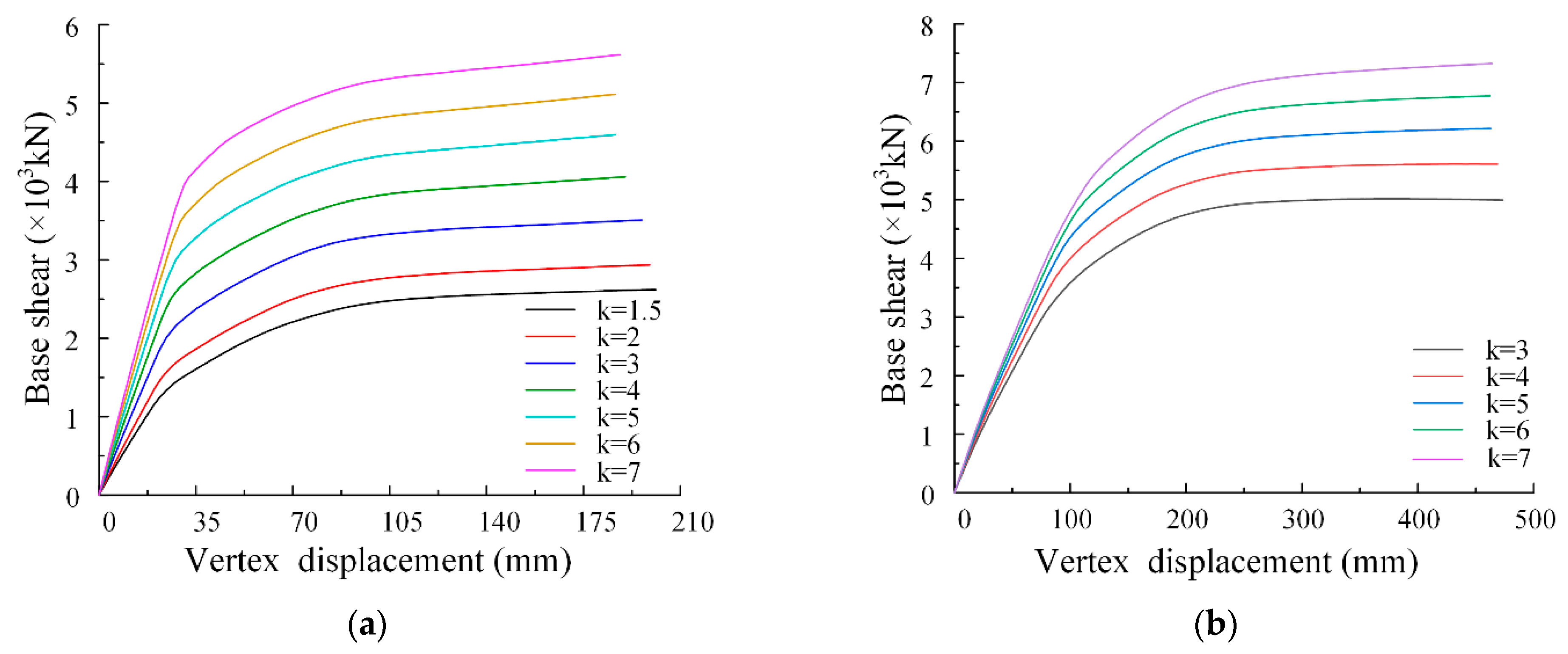
The base shear-vertex displacement curve of the structure under each stiffness ratio is shown in Figure 12. The braces could significantly enhance the seismic performance of the structure. The stiffness and capacity of the PCF-BRB structure increased with the stiffness ratio. For the four-story structures, the stiffness and capacity increased by 240% and 124%, respectively, when the stiffness ratio increased from 1.5 to 7. For the 12-story structures, the stiffness and capacity increased by 33% and 53%, respectively, when the stiffness ratio increased from three to seven.

4.2. Plastic Hinge Development

The braces could improve the lateral stiffness of the structure, but they also exerted a large axial force on the adjacent columns [48]. Excessive axial pressure reduced the ductility of the column, while excessive axial tension placed the column in a pulled state [49], resulting in severe concrete cracking [48,50]. More importantly, unlike cast-in-place concrete frame-steel brace structures, braces need to provide greater lateral stiffness in PCF-BRB structure, resulting in a larger axial force transmitted to adjacent columns, which made the columns prone to premature failure. Therefore, attention should be paid to the damage mechanism of the structure.
The damage mechanism of a frame structure is usually divided into three kinds: beam hinge, column hinge, and beam-column hinge mixing mechanisms. The principle of this classification is the time, position, and level of plastic hinge appearance. In the beam hinge mechanism, the plastic hinge appears at the beam end first, and the plastic hinge is only located at the beam ends and the column bottom. The column hinge mechanism is the story-damage mechanism. The plastic hinge first appears at the column end and is mainly distributed at the column end, while the frame beam end has no plastic hinge. When the column forms plastic hinges on both ends, the floor yields and forms a weak floor. The beam-column hinge mixing mechanism allows the plastic hinges to develop at the beam and column ends.
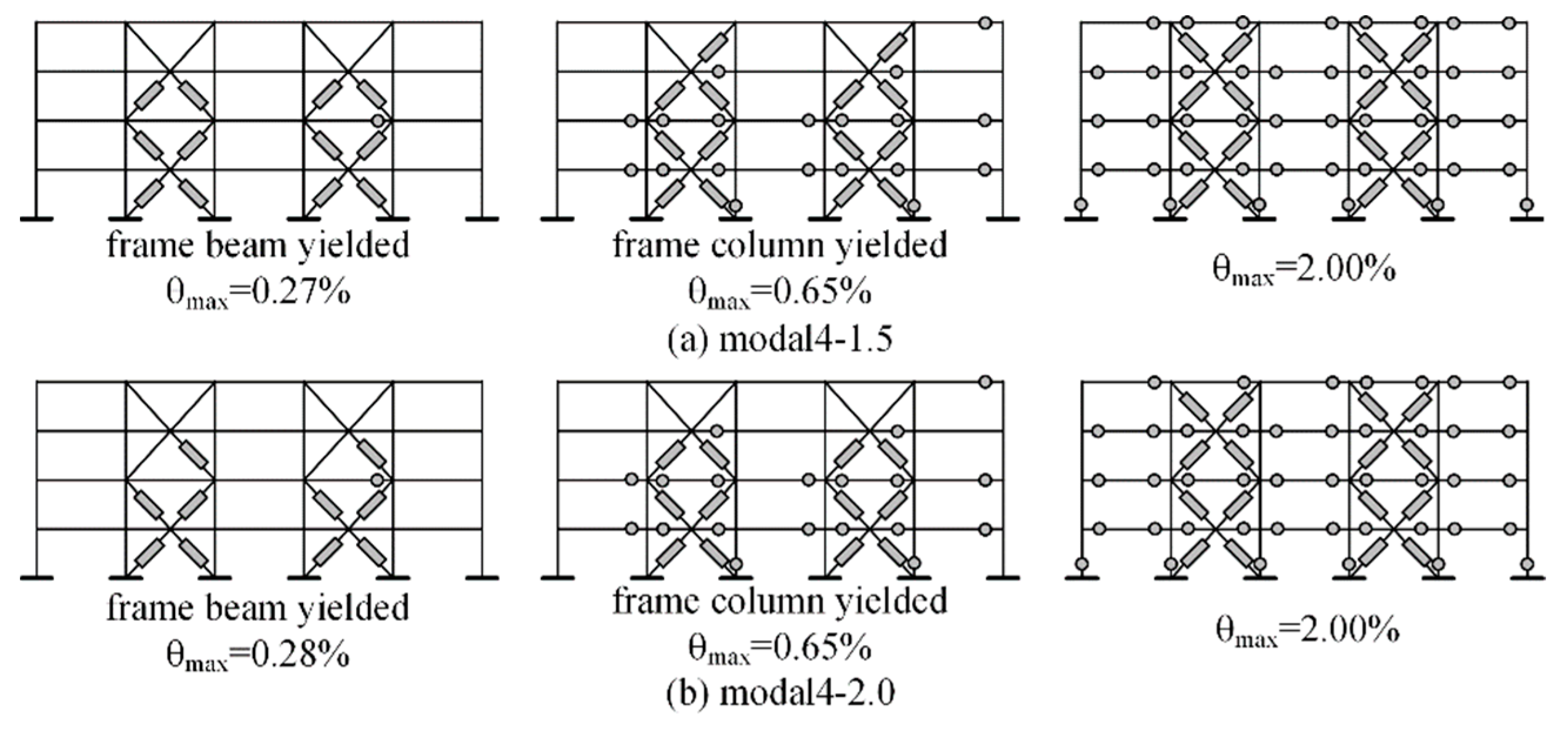
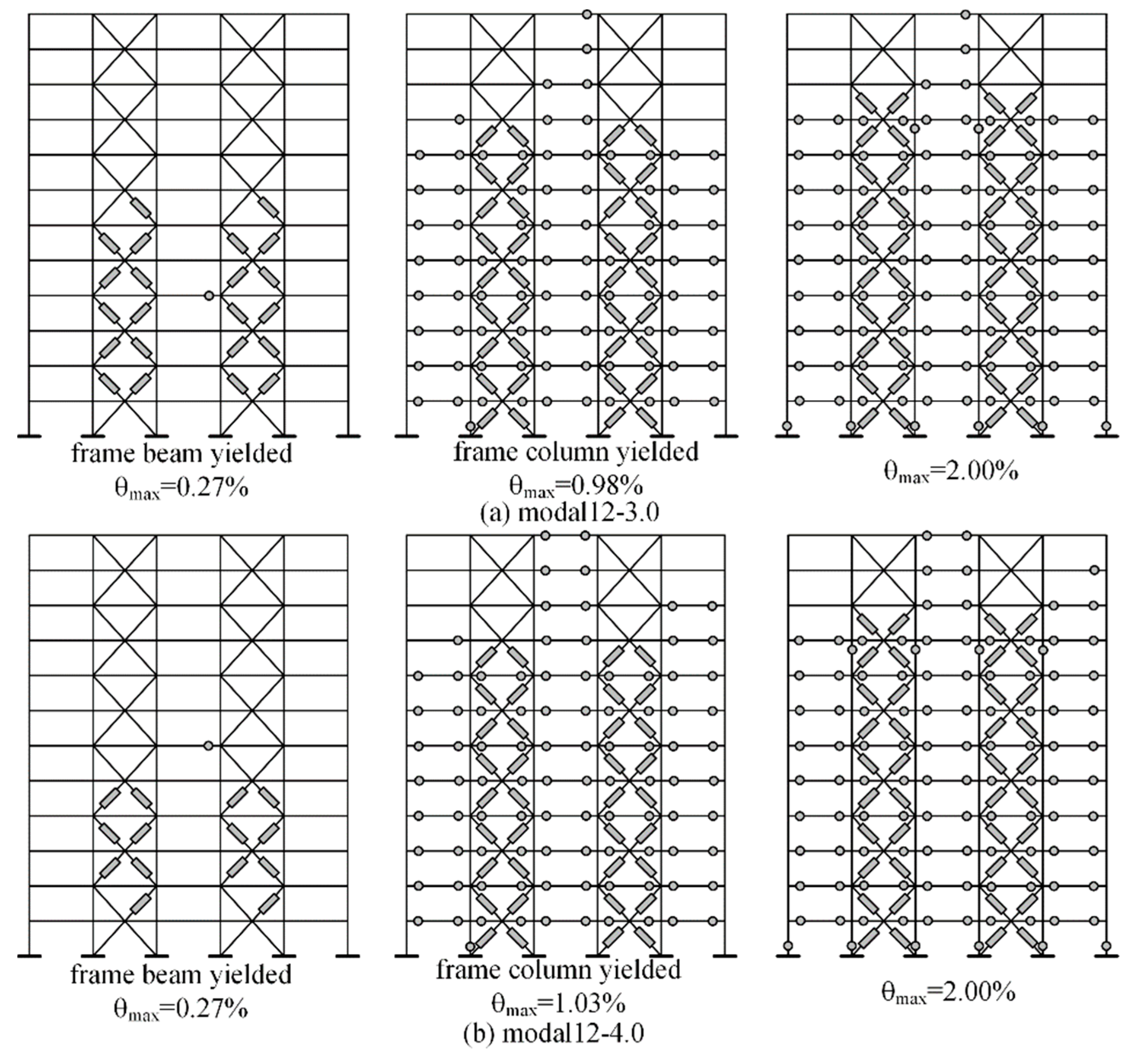
The beam-column yield sequence of the 4- and 12-story PCF-BRB structures under static pushover analysis are shown in Figure 13 and Figure 14, respectively. To discuss the influence of the stiffness ratio on the structure damage mechanism, we studied the following three moments: (1) the frame beam begins to yield; (2) the frame column begins to yield; (3) the maximum inter-story drift reaches 2.0%.
In modal4-1.5, the frame beam yielded before the frame column, and the corresponding maximum inter-story drifts were 0.27% and 0.65%, respectively. When the maximum inter-story drift reached 2.00%, the plastic hinge was concentrated at the beam ends and the column bottom, which is a beam hinge damage mechanism. In modal4-4.0, the frame beam yielded before the frame column. When the maximum inter-story drift reached 2.00%, plastic hinges appeared at the two- and three-floor columns. The damage mechanism follows the beam-column hinge mixing mechanism.
In modal12-3.0, the frame beam yielded before the frame column, and the corresponding maximum inter-story drift was 0.27% and 0.98%, respectively. When the maximum inter-story drift reached 2.00%, the plastic hinge was concentrated at the beam end, the column bottom, and the top of the 9-story, roughly the beam hinge damage mechanism. In modal12-5.0, the two-floor columns connected with the braces yielded tension before the bottom column when the maximum inter-story drift reached 0.73%. Plastic hinges appeared at most beam ends when the maximum inter-story drift reached 2.00%. In addition, the column on the one-three-floor and nine-floor formed plastic hinges, resulting in a beam-column hinge mixing mechanism. In modal12-7.0, plastic hinges formed at the top of the bottom column when the maximum inter-story drift reached 2.00%, indicating a story-damage mechanism in the first story.

5. Dynamic Time History Analysis

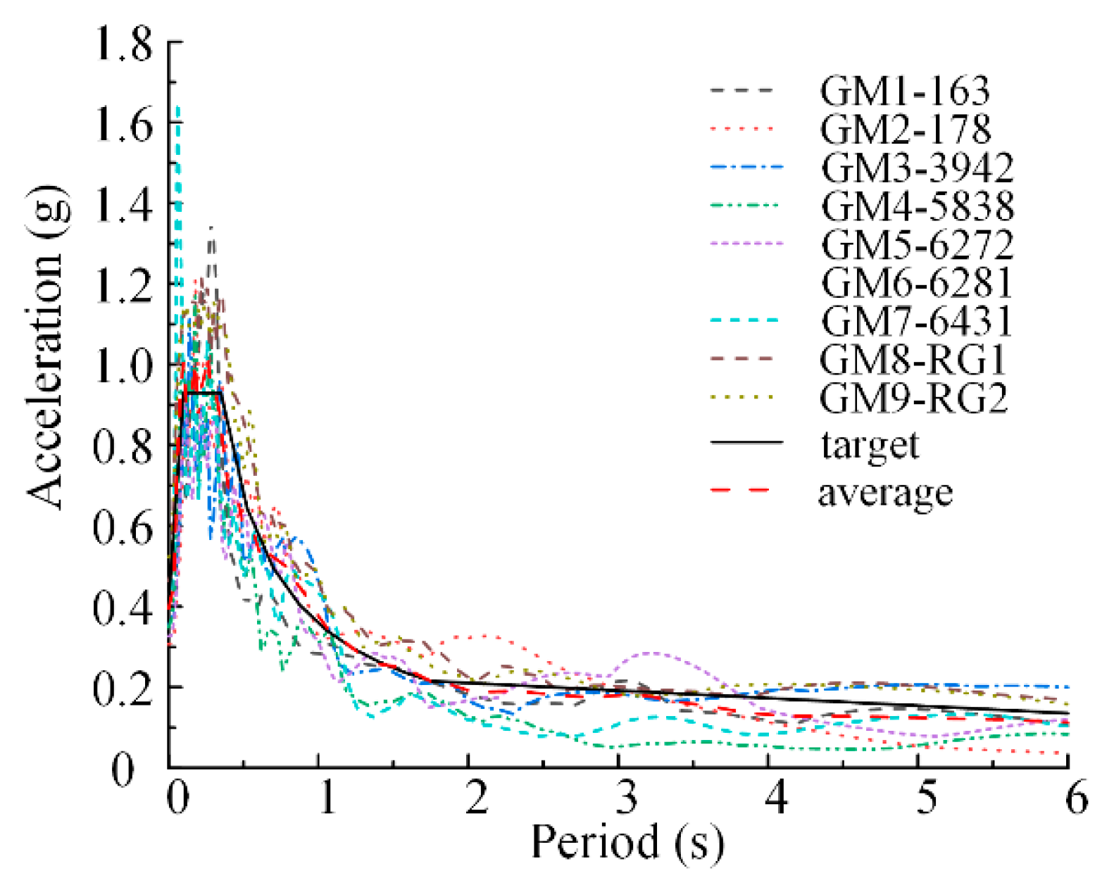
A total of nine seismic waves were selected [47], including seven natural waves from the Pacific Earthquake Engineering Research Center and two artificial waves. The maximum peak acceleration of the nine selected seismic waves was scaled to 4 m/s2 for time history analysis under rare earthquakes. The comparison between the response spectrum of seismic waves and the standard response spectrum is shown in Figure 15. The average of the nine seismic waves was in good agreement with the target.
In the PCF-BRB structure, the BRBs have two main functions: (1) improving the stiffness and reducing the inter-story deformation of the structure; (2) dissipating the input seismic energy, making the structure damage mainly focused on the BRBs, reducing the damage of the frame and protect the frame. Thus, the subsequent section analyzes the maximum inter-story drift and energy dissipation ratio of BRBs.

5.1. Maximum Inter-Story Drift

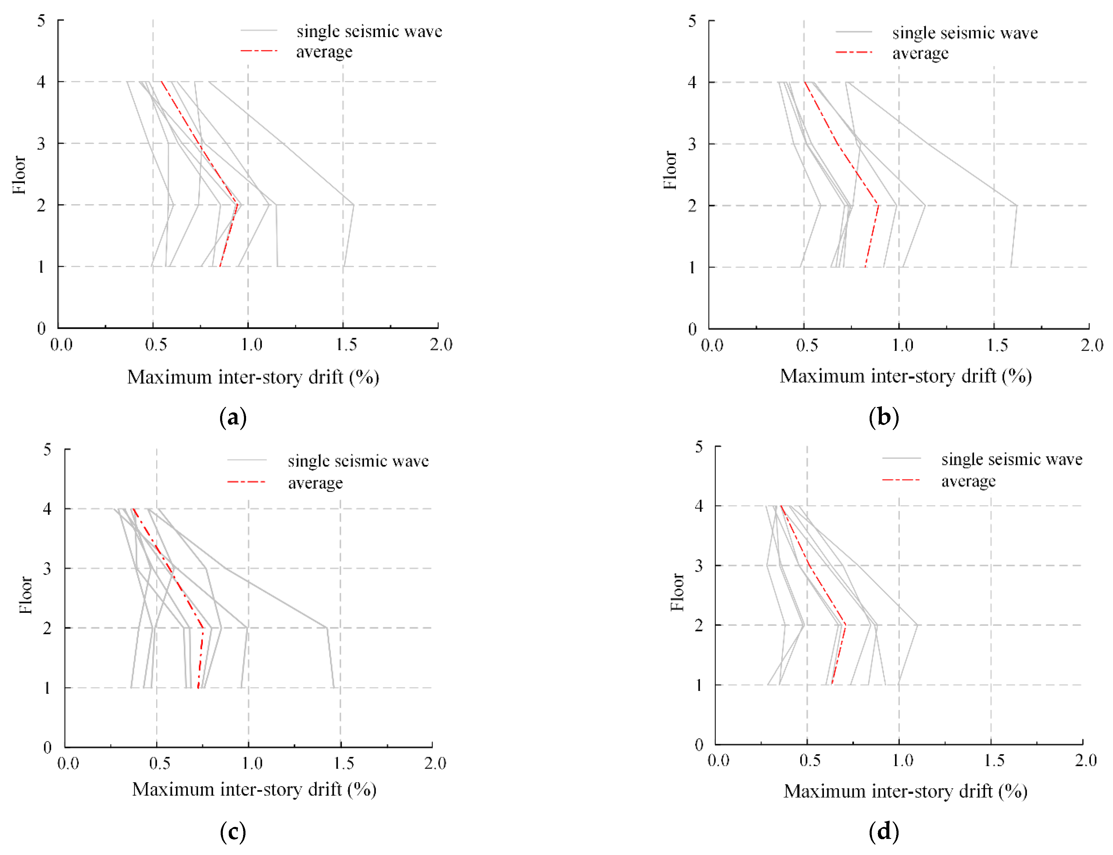
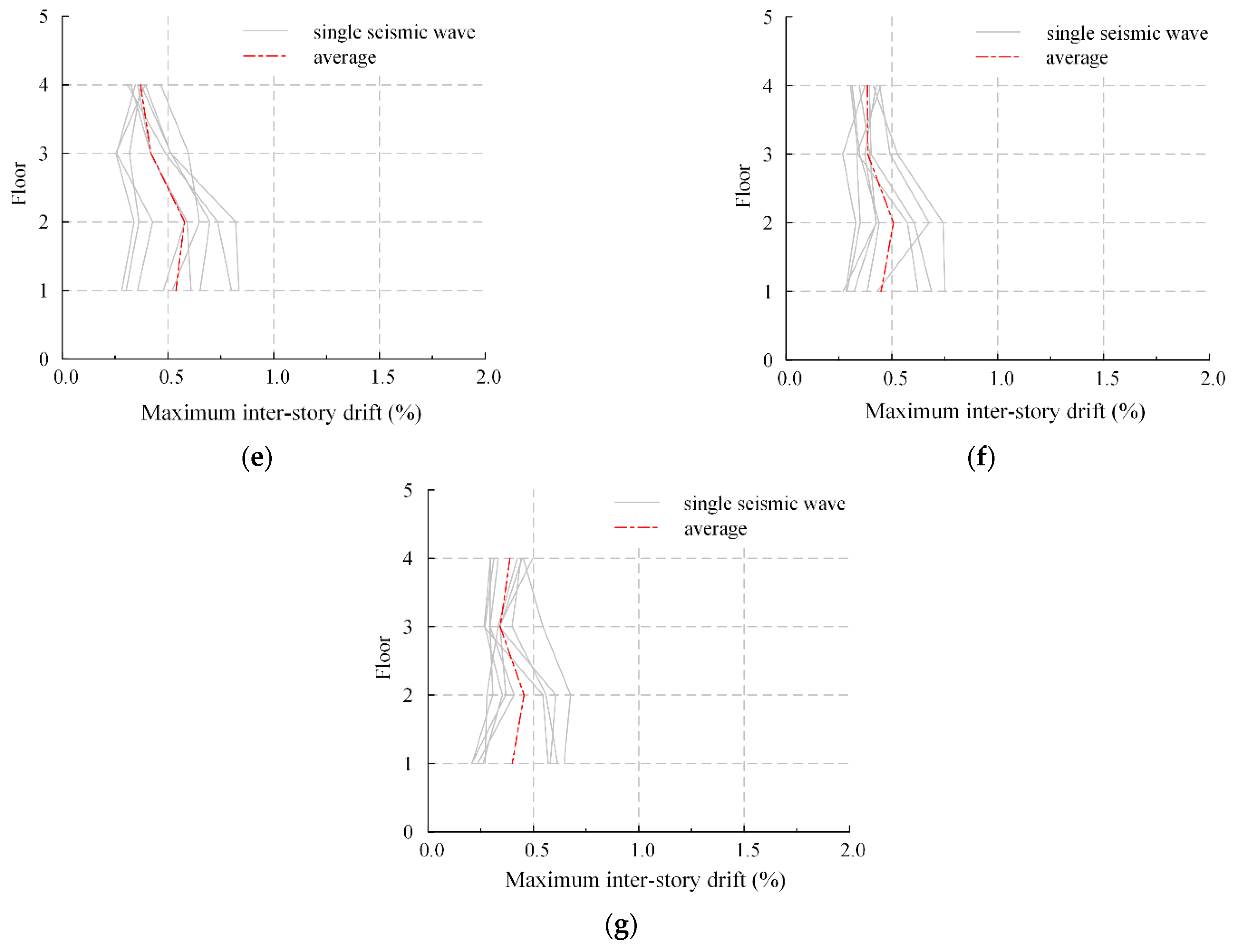
The maximum inter-story drift responses of the four-story PCF-BRB structures are shown in Figure 16. The maximum inter-story drifts were all less than 2.00% and occurred on the second floor. As the stiffness ratio increased, the maximum inter-story drift continuously decreased.
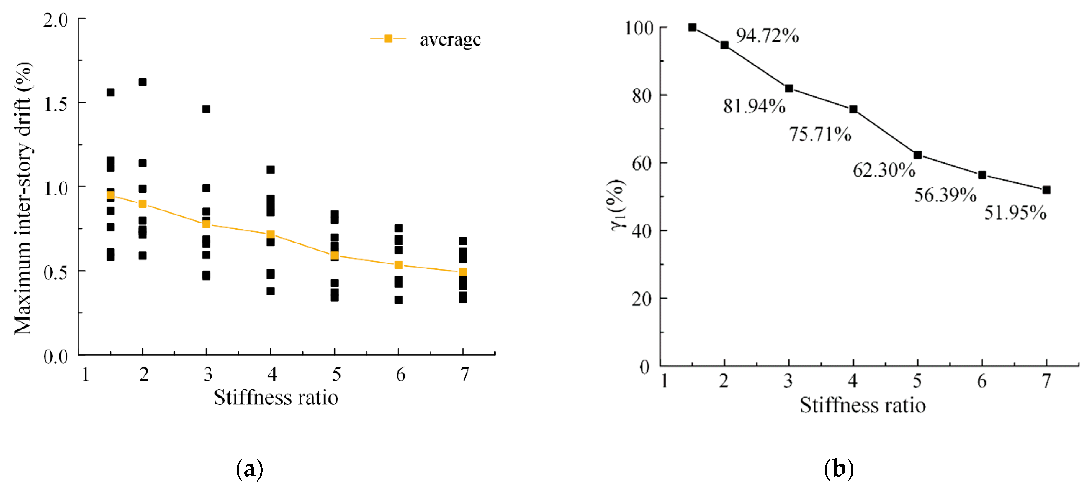
Figure 17a shows that the average maximum inter-story drift changed with the increase in the stiffness ratio. The larger the stiffness ratio, the smaller the average maximum inter-story drift decreases. The definition of γ1 in Figure 17b is expressed as Equation (12), which shows the average variation of maximum inter-story drift. When the stiffness ratio was 6.0, the average maximum inter-story drift decreased to 56.39%. When the stiffness ratio was 7.0, the average maximum inter-story drift decreased to 51.95%. The reduction was less than 5%.
γ 1 = θ A V G m a x , u θ A V G m a x , 1.5
where θAVGmax,u is the average maximum inter-story drift when the stiffness ratio is u; θAVGmax,1.5 is the average maximum inter-story drift when the stiffness ratio is 1.5.
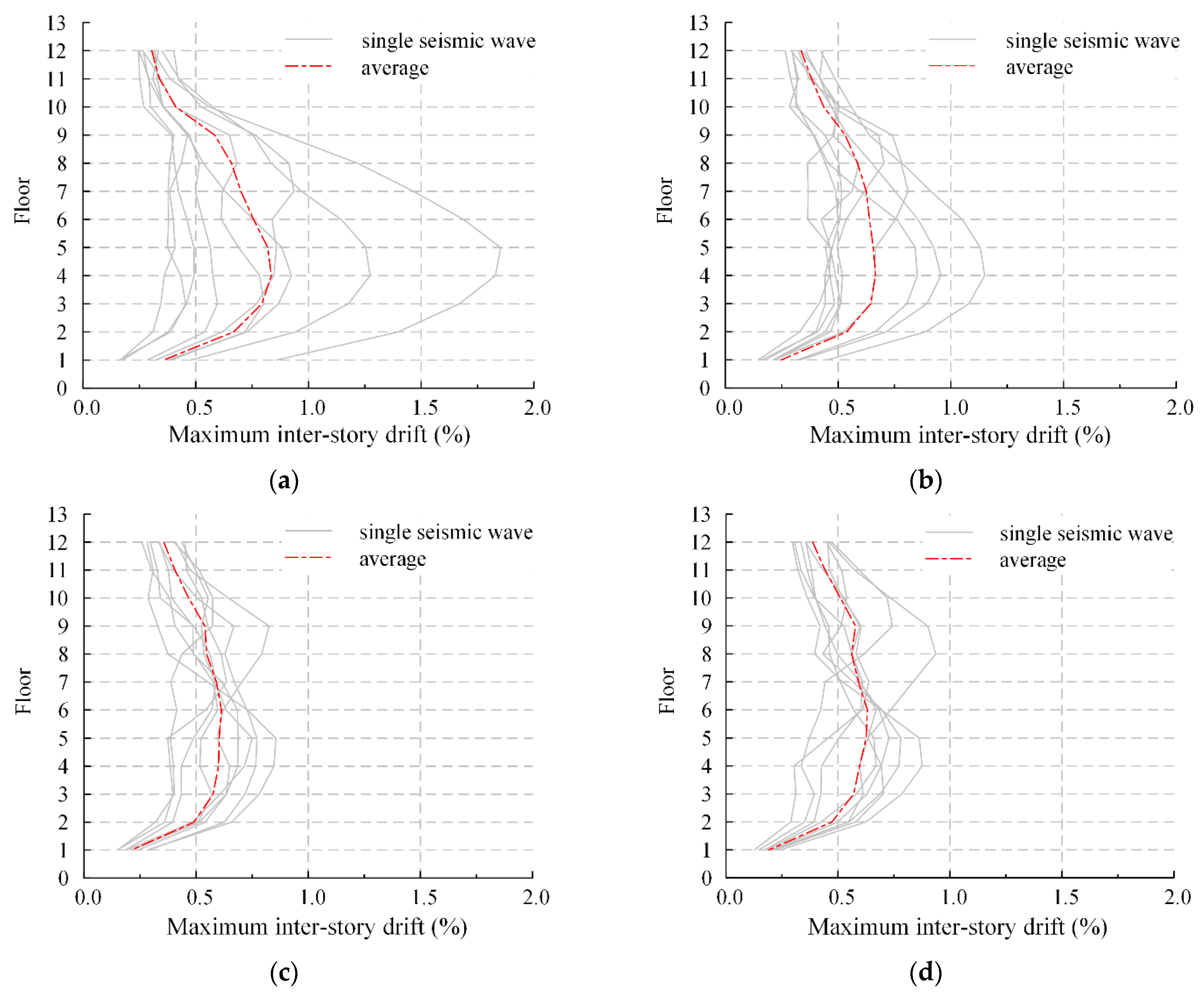
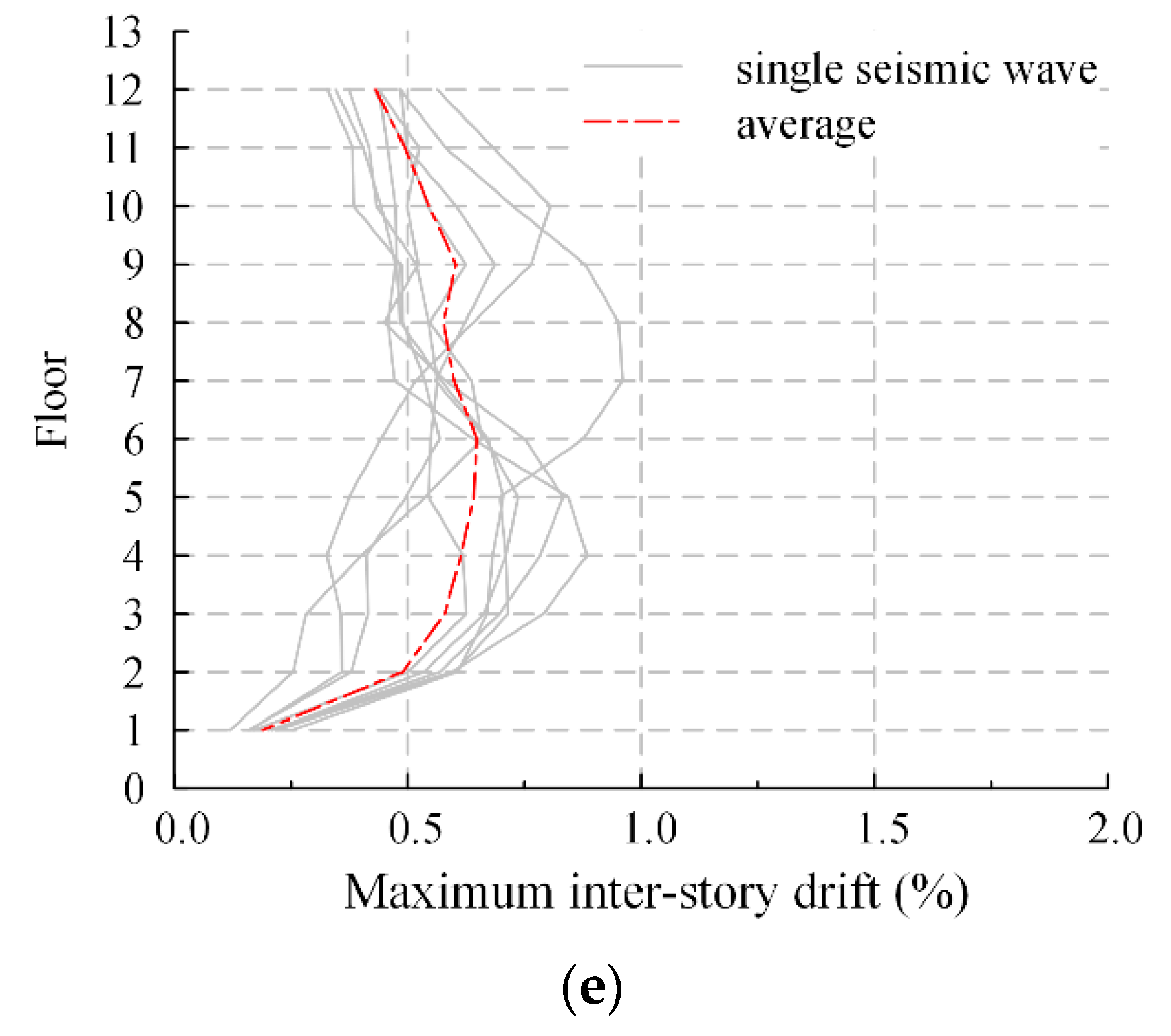
The maximum inter-story drift responses of the 12-story structures are shown in Figure 18. The maximum inter-story drifts were all less than 2.00% and occurred in the middle story of the structure.
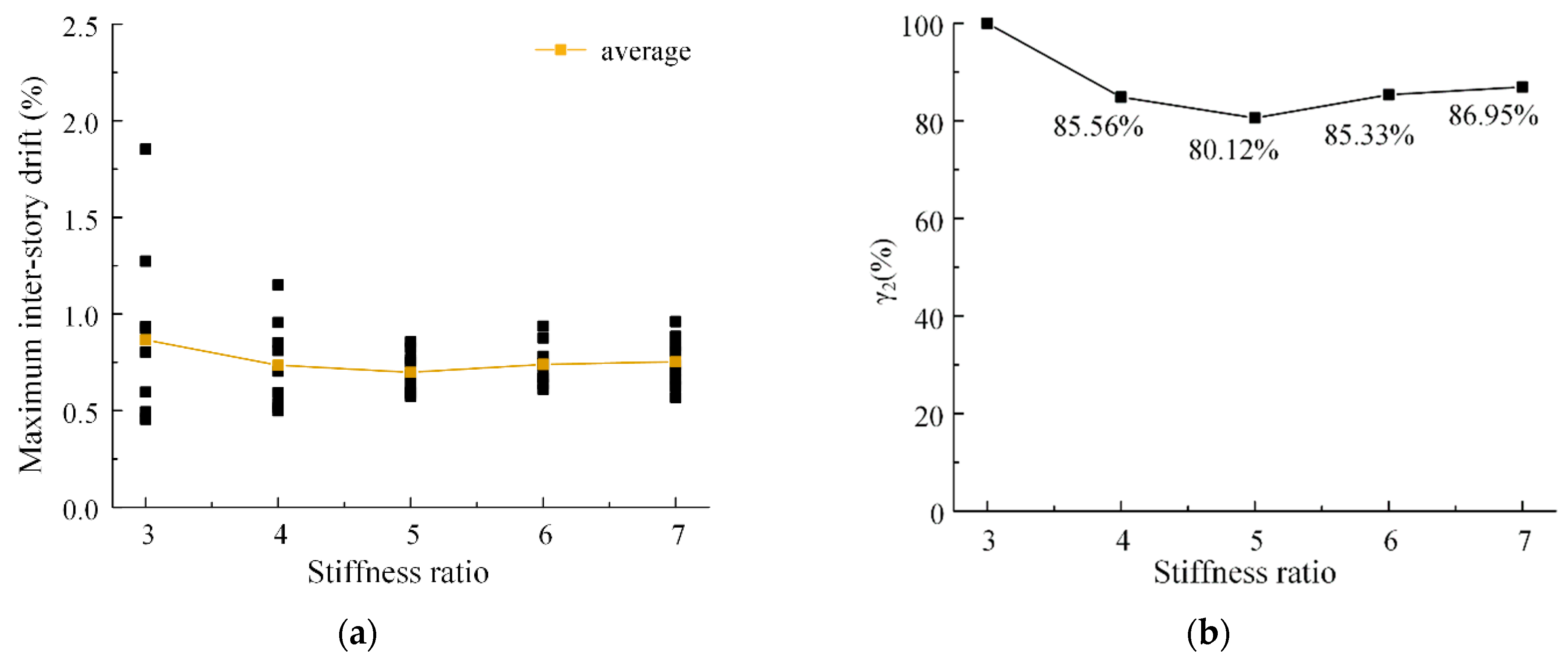
Figure 19a shows that the average of the maximum inter-story drift changed with the stiffness ratio. The definition of γ2 in Figure 19b is expressed as Equation (13), which shows the average variation of maximum inter-story drift. When the stiffness ratio was 5.0, the average maximum inter-story drift decreased to 80.12%, and when the stiffness ratio was greater than 5.0, the average maximum inter-story drift increased instead. The reason is that at this time, the strength of BRBs had seriously affected the seismic performance of frame columns. In addition to the bottom frame columns, frame columns of multiple floors yielded, which led to the decline of the seismic capacity of the overall structure.
γ 2 = θ A V G m a x , v θ A V G m a x , 3.0
where θAVGmax,v is the average maximum inter-story drift of the structure when the stiffness ratio is v; θAVGmax,3.0 is the average maximum inter-story drift of the structure when the stiffness ratio is 3.0.

5.2. Energy Dissipation Ratio of BRBs

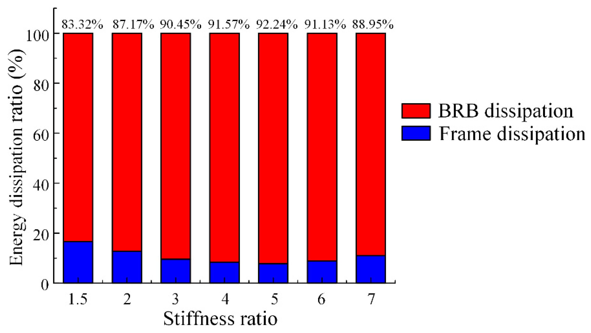
In the 4-story PCF-BRB structure, the change of the energy dissipation ratio of BRBs with the stiffness ratio is shown in Figure 20. When the stiffness ratio was 1.5, the energy dissipation ratio reached 83.32%. Then, with the stiffness ratio increased, the energy dissipation ratio further increased. When the stiffness ratio reached 5.0, the energy dissipation ratio reached 92.24%. When the stiffness ratio was greater than 5.0, the energy dissipation ratio began to decline. The reason is that the higher stiffness of the BRBs caused the delay of BRBs yielding, reducing the cumulative plastic energy.
In the 12-story PCF-BRB structure, the change in the energy dissipation ratio of BRBs with the stiffness ratio is shown in Figure 21. When the stiffness ratio was 3.0, the energy dissipation ratio of BRBs was 73.61%. Then the energy dissipation ratio increased with the stiffness ratio. When the stiffness ratio was 5.0, the energy dissipation ratio reached the maximum of 79.11%. When the stiffness ratio was greater than 5.0, the energy dissipation ratio decreased due to the delay of BRBs entering the plastic state.

6. Recommended Range of the Stiffness Ratio

Based on the above analyses, increasing the stiffness ratio could improve the structure’s stiffness and reduce the structure’s inter-story drift. However, with the increase of the stiffness ratio, the enhancement effect of BRB gradually decreased. With the rise of the stiffness ratio, the column suffered early yielding and failure, leading to the unfavorable beam-column hinge mixing damage mechanism and even the story-damage mechanism. Also, the energy dissipation ratio of BRBs began to decrease when the stiffness ratio was over a specific value due to the delay of BRBs yielding. Therefore, the recommended range of stiffness ratio should consider these factors comprehensively.
The four-story PCF-BRB structure models represent the low-rise PCF-BRB structures. The stiffness ratio should be no more than 5.0 to dissipate the maximum energy proportion by BRBs. Also, the stiffness ratio should be less than 3.0 to avoid the beam-column hinge mixing damage mechanism. Considering the lower limit of stiffness ratio is 1.5, specified in GB 50011-2010 [47], we suggest that the recommended range of the stiffness ratio is 1.5 ≤ k ≤ 3.0 for the low-rise PCF-BRB structures.
The 12-story PCF-BRB structure models represent the high-rise PCF-BRB structures. The stiffness ratio should be no more than 5.0 to dissipate the maximum energy proportion by BRBs. Also, the stiffness ratio should be less than 4.0 to avoid the beam-column hinge mixing damage mechanism. Considering the lower limit of stiffness ratio 3.0 specified in GB 50011-2010 [47], we suggest that the recommended range of the stiffness ratio is 3.0 ≤ k ≤ 4.0 for the high-rise PCF-BRB structures.

7. Conclusions

This study established the analysis model of 4- and 12-story PCF-BRB structures with different stiffness ratios. Through static pushover analysis and dynamic time history analysis, the influence of stiffness ratios on the structure’s seismic performance was studied to determine the recommended range of the stiffness ratio for seismic design. The conclusions are as follows:
(1)
The simulative results have shown that with an increase in the stiffness ratio, the stiffness and strength of the PCF-BRB structure were constantly increasing. However, for the four-story PCF-BRB structure, the greater the stiffness ratio, the smaller the reduction of the average maximum inter-story drift. For the 12-story PCF-BRB structure, when the stiffness ratio was 5.0, the maximum inter-story drift reduction reached the maximum.
(2)
For both the 4- and 12-story PCF-BRB structures, when the stiffness ratio was over 4.0 and 5.0, respectively, the damage mechanism of the structures changed from the beam hinge damage mechanism to the beam-column hinge mixing damage mechanism. Further increasing the stiffness ratio resulted in the story-damage mechanism of the PCF-BRB structures, which significantly impacted the structural seismic performance.
(3)
For the 4-story PCF-BRB structure and the 12-story PCF-BRB structure, the energy dissipation ratio of BRBs reached the maximum when the stiffness ratio increased to 5.0. When the stiffness ratio continued to increase, the consumption ratio decreased instead due to the delay of BRB entering the plastic state, which led to less cost-efficiency.
(4)
For low-rise, PCF-BRB structures, the recommended range of stiffness ratio should be 1.5 ≤ k ≤ 3.0; for high-rise PCF-BRB structures, the recommended range of the stiffness ratio should be 3.0 ≤ k ≤ 4.0. In the lateral stiffness ratio design method, the stiffness ratio can be used for the detailed design of BRBs.

Author Contributions

Conceptualization, Y.H.; methodology, Y.H.; software, T.T.; validation, T.T.; data curation, T.T.; writing—original draft preparation, Q.W.; writing—review and editing, Q.W.; visualization, T.T.; supervision, Y.H. All authors have read and agreed to the published version of the manuscript.

Funding

This research was funded by the Natural Science Foundation of Hunan Province with Grant No. 2020JJ2003 and No. 2020RC5005.

Institutional Review Board Statement

Not applicable.

Informed Consent Statement

Not applicable.

Data Availability Statement

The data presented in this study are available upon reasonable request from the corresponding author.

Acknowledgments

Support from the Natural Science Foundation of Hunan Province are gratefully acknowledged.

Conflicts of Interest

The authors declare no conflict of interest.

References

  1. Black, R.G.; Wenger, W.; Popov, E.P. Inelastic Buckling of Steel Struts under Cyclic Load Reversals. In Report No. UCB/EERC-80/40; Earthquake Engineering Research Center, University of California: Berkeley, CA, USA, 1980. [Google Scholar]
  2. Kimura, K.; Yoshioka, K.; Takeda, T. Tests on braces encased by mortar in-filled steel tubes. In Summaries of Technical Papers of Annual Meeting; Architectural Institute of Japan: Tokyo, Japan, 1976. [Google Scholar]
  3. Ozcelik, R.; Dikiciasik, Y.; Erdil, E.F. The development of the buckling restrained braces with new end restrains. J. Constr. Steel Res. 2017, 138, 208–220. [Google Scholar] [CrossRef]
  4. Zhou, Y.; Shao, H.; Cao, Y.; Lui, E.M. Application of buckling-restrained braces to earthquake-resistant design of buildings: A review. Eng. Struct. 2021, 246, 112991. [Google Scholar] [CrossRef]
  5. Ghamari, A.; Haeri, H.; Johari Naeimi, A.; Najmi, Z.; Sarfarazi, V. Behavior of double K-BRB braces under lateral loading. J. Cent. South Univ. 2021, 28, 2394–2406. [Google Scholar] [CrossRef]
  6. Aksoylu, C.; Özkılıç, Y.O.; Arslan, M.H. Damages on prefabricated concrete dapped-end purlins due to snow loads and a novel reinforcement detail. Eng. Struct. 2020, 225, 111225. [Google Scholar] [CrossRef]
  7. Gemi, L.; Aksoylu, C.; Yazman, Ş.; Özkılıç, Y.O.; Arslan, M.H. Experimental investigation of shear capacity and damage analysis of thinned end prefabricated concrete purlins strengthened by CFRP composite. Compos. Struct. 2019, 229, 111399. [Google Scholar] [CrossRef]
  8. Özkılıç, Y.O.; Aksoylu, C.; Arslan, M.H. Experimental and numerical investigations of steel fiber reinforced concrete dapped-end purlins. J. Build. Eng. 2021, 36, 102119. [Google Scholar] [CrossRef]
  9. Chaturvedi, R.; Sharma, A.; Islam, A. Design analysis of BRB energy dissipated devices in commercial building structures. Mater. Today 2021, 45, 2949–2952. [Google Scholar] [CrossRef]
  10. Yakhchalian, M.; Yakhchalian, M.; Asgarkhani, N. An advanced intensity measure for residual drift assessment of steel BRB frames. Bull. Earthq. Eng. 2021, 19, 1931–1955. [Google Scholar] [CrossRef]
  11. Zhou, X.; Sun, T.; Sun, B.; Ma, N.; Ou, J. Vibration-Reduction Strategy for High-Rise Braced Frame Using Viscoelastic-Yielding Compounded BRB. Buildings 2022, 12, 1159. [Google Scholar] [CrossRef]
  12. Macrae, G.; Lee, C.L.; Vazquez-Colunga, S.; Cui, J.; Alizadeh, S.; Jia, L.J. BRB system stability considering frame out-of-plane loading and deformation zone. Bull. N. Z. Soc. Earthq. Eng. 2021, 54, 31–39. [Google Scholar] [CrossRef]
  13. Özkılıç, Y.O. Interaction of flange and web slenderness, overstrength factor and proposed stiffener arrangements for long links. J. Constr. Steel Res. 2022, 190, 107150. [Google Scholar] [CrossRef]
  14. Özkılıç, Y.O.; Bozkurt, M.B.; Topkaya, C. Mid-spliced end-plated replaceable links for eccentrically braced frames. Eng. Struct. 2021, 237, 112225. [Google Scholar] [CrossRef]
  15. Tsai, C.Y.; Tsai, K.C.; Chen, L.W.; Wu, A.C. Seismic performance analysis of BRBs and gussets in a full-scale 2-story BRB-RCF specimen. Earthq. Eng. Struct. Dyn. 2018, 47, 2366–2389. [Google Scholar] [CrossRef]
  16. Bai, J.; Chen, H.; Jin, S. Investigation on the interaction between BRBs and the RC frame in BRB-RCF systems. Eng. Struct. 2021, 243, 112685. [Google Scholar] [CrossRef]
  17. Guerrero, H.; Teran-Gilmore, A.; Zamora, E.; Escobar, J.A.; Gómez, R. Hybrid Simulation Tests of a Soft Storey Frame Building Upgraded with a Buckling-Restrained Brace (BRB). Exp. Technol. 2020, 44, 553–572. [Google Scholar] [CrossRef]
  18. Oviedo-Amezquita, J.A.; Jaramillo-Santana, N.; Blandon-Uribe, C.A.; Bernal-Zuluaga, A.M. Development and validation of an acceptance criteria and damage index for buckling-restrained braces (BRB). J. Build. Eng. 2021, 43, 102534. [Google Scholar] [CrossRef]
  19. Guerrero, H.; Ji, T.; Escobar, J.A.; Teran-Gilmore, A. Effects of Buckling-Restrained Braces on reinforced concrete precast models subjected to shaking table excitation. Eng. Struct. 2018, 163, 294–310. [Google Scholar] [CrossRef]
  20. Ruiz, S.E.; Santos-Santiago, M.A.; Bojórquez, E.; Orellana, M.A.; Valenzuela-Beltrán, F.; Bojórquez, J.; Barraza, M. BRB retrofit of mid-rise soft-first-story RC moment-frame buildings with masonry infill in upper stories. J. Build. Eng. 2021, 38, 101783. [Google Scholar] [CrossRef]
  21. Ghazal, H.; Mwafy, A. Seismic Fragility Assessment of an Existing Multi-Span RC Bridge Equipped with Risk Mitigation Systems. Buildings 2022, 12, 982. [Google Scholar] [CrossRef]
  22. Cao, X.Y.; Feng, D.C.; Wu, G.; Zeng, Y.H. Reusing & replacing performances of the AB-BRB with thin-walled concrete-infilled steel shells. Thin-Walled Struct. 2020, 157, 107069. [Google Scholar] [CrossRef]
  23. Bashiri, M.; Toufigh, V. Numerical and experimental investigation on a BRB confined with partially carbon fiber reinforced polymer (CFRP). Eng. Struct. 2020, 223, 111150. [Google Scholar] [CrossRef]
  24. Al-Sadoon, Z.A.; Saboor Karzad, A.; Sagheer, A.; AlHamaydeh, M. Replaceable fuse buckling-restrained brace (BRB): Experimental cyclic qualification testing and NLFEA modeling. Structures 2022, 39, 997–1015. [Google Scholar] [CrossRef]
  25. ÖZkiliÇ, Y.O. The Effects of Steel Core Imperfection, Gap Size and Friction Coefficienton the Behavior of All-Steel Buckling Restrained Braces. Düzce Univ. J. Sci. Technol. 2021, 9, 1342–1357. [Google Scholar] [CrossRef]
  26. Miao, F.; Nejati, F.; Zubair, S.A.M.; Yassin, M.E. Seismic Performance of Eccentrical Braced Frame Retrofitted by Box Damper in Vertical Links. Buildings 2022, 12, 1506. [Google Scholar] [CrossRef]
  27. Özkılıç, Y.O.; Bozkurt, M.B.; Topkaya, C. Evaluation of seismic response factors for BRBFs using FEMA P695 methodology. J. Constr. Steel Res. 2018, 151, 41–57. [Google Scholar] [CrossRef]
  28. Zhao, Y.; Guo, Y.L. Research on design method of buckling-restrained braced frame. Build. Struct. 2010, 40, 38–43. [Google Scholar] [CrossRef]
  29. Shen, P.S. High-Rise Building Structure Design; China Building Industry Press: Beijing, China, 2017. [Google Scholar]
  30. Hong, L.L. Continuous Collapse Resistance Analysis and Overall Stability Evaluation of RC Frame Considering Floor Effect. Master’s Thesis, Hunan University, Changsha, China, 2020. [Google Scholar]
  31. Beijing Zhuxinda Engineering Consulting Co., Ltd. Sap2000 Technical Guide and Engineering Applications; People’s Communications Press Co., Ltd.: Beijing, China, 2018; Volume 1, pp. 283–287. [Google Scholar]
  32. Mander, J.B.; Priestley, M.; Park, R. Theoretical Stress-Strain Model for Confined Concrete. J. Struct. Eng. 1988, 114, 1804–1826. [Google Scholar] [CrossRef] [Green Version]
  33. GB 50010-2010; Code for Design of Concrete Structures (2015 Version). Ministry of Housing and Urban-Rural Development of the People’s Republic of China: Beijing, 2015.
  34. Mao, C.J. Design and Seismic Performance Analysis of New BRB Energy Dissipation Shear Wall Structure. Master’s Thesis, Zhengzhou University, Zhengzhou, China, 2017. [Google Scholar]
  35. Li, G.Q.; Sun, F.F.; Chen, S.W. Development and experiential study of large-tonnage domestic TJ II buckling restrained brace. Prog. Steel Build. Struct. 2009, 11, 22–26. [Google Scholar]
  36. Chen, Q.; Wang, C.L.; Meng, S.; Zeng, B. Effect of the unbonding materials on the mechanic behavior of all-steel buckling-restrained braces. Eng. Struct. 2016, 111, 478–493. [Google Scholar] [CrossRef]
  37. Gu, L.Z.; Gao, X.Y.; Xu, J.W. Experimental research on seismic performance of BRB concrete frames. J. Archit. Archit. 2011, 32, 101–111. [Google Scholar] [CrossRef]
  38. Wu, K.; Tao, Z.; Pan, W.; Bai, Y.; Yu, W. Experimental study on seismic performance of buckling restrained braced-RC frames with different stiffness ratios. J. Build. Struct. 2021, 42, 43–54. [Google Scholar] [CrossRef]
  39. Yang, X. Study on Seismic Behavior of RC Frame Structures with Few Steel Braces. Master’s Thesis, Tsinghua University, Beijing, China, 2015. [Google Scholar]
  40. Sahoo, D.R.; Chao, S.-H. Stiffness-Based Design for Mitigation of Residual Displacements of Buckling-Restrained Braced Frames. J. Struct. Eng. 2015, 141, 04014229. [Google Scholar] [CrossRef]
  41. Xu, L.; Fan, X.; Li, Z. Seismic Assessment of Buildings with Prepressed Spring Self-Centering Energy Dissipation Braces. J. Struct. Eng. 2020, 146, 04019190. [Google Scholar] [CrossRef]
  42. Huang, L.; Feng, P.; Zhang, J. Prefabricated Concrete Structure; China Building Industry Press: Beijing, China, 2020. [Google Scholar]
  43. Yu, Z.W. Study and Optimization of Seismic Performance of Planar Irregular Frame Structures. Master’s Thesis, Xi’an University of Architecture and Technology, Xi’an, China, 2010. [Google Scholar]
  44. Erochko, J.A. Improvements to the Design and Use of Post-Tensioned Self-Centering Energy-Dissipative (SCED) Braces. Ph.D. Thesis, University of Toronto, Toronto, Canada, 2013. [Google Scholar]
  45. Zhou, W.W. Influence of Frame Overturning Moment Proportion on Seismic Performance of RC Frame Shear Wall Structures. Ph.D. Thesis, Hunan University, Changsha, China, 2017. [Google Scholar]
  46. Antony, A.; Neeraja, N. Seismic Performance of Modular Steel Braced Building Equipped with BRB Braces. In Proceedings of the SECON’21, International Conference on Structural Engineering and Construction Management; Lecture Notes in Civil Engineering; Springer International Publishing: Berlin/Heidelberg, Germany, 2022; pp. 529–538. [Google Scholar]
  47. GB 50011-2010; Code for Seismic Design of Buildings (2016 Version). Ministry of Housing and Urban-Rural Development of the People’s Republic of China: Beijing, China, 2016.
  48. Jia, D.D. Research of Pseudo Static Test on Variable Axial Force and Rotation of Reinforced Concrete Column. Master’s Thesis, Harbin Institute of Technology, Harbin, China, 2016. [Google Scholar]
  49. Rahimi, A.; Maheri, M.R. The effects of retrofitting RC frames by X-bracing on the seismic performance of columns. Eng. Struct. 2018, 183, 813–830. [Google Scholar] [CrossRef]
  50. Saatcioglu, M.; Ozcebe, G. Response of Reinforced Concrete Columns to Simulated Seismic Loading. Aci Struct. J. 1989, 86, 3–12. [Google Scholar]
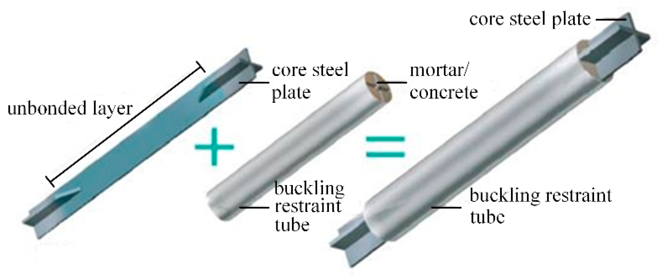
Figure 1. Buckling-restrained brace.
Buildings 12 01818 g001
Figure 2. Fiber division of beam and column section: (a) beam and (b) column.
Buildings 12 01818 g002
Figure 3. Material stress-strain relationship curve: (a) reinforcement, (b) concrete compression, and (c) concrete tension.
Buildings 12 01818 g003
Figure 4. Buckling-restrained brace hysteresis curve.
Buildings 12 01818 g004
Figure 5. Rigid zone of the braced frame substructure.
Buildings 12 01818 g005
Figure 6. Sketch diagram: (a) BLY225-1, (b) V1, (c) V2, (d) BRBCF3, and (e) BRBF3 and BRBF5.
Buildings 12 01818 g006aBuildings 12 01818 g006bBuildings 12 01818 g006c
Figure 7. Comparison of simulation and test hysteresis curve: (a) BLY225−1, (b) V1, (c) V2, (d) BRBCF3; (e) BRBF3; (f) BRBF5.
Buildings 12 01818 g007aBuildings 12 01818 g007b
Figure 8. Sketch diagram of buckling-restrained brace.
Buildings 12 01818 g008
Figure 9. Structure layout: (a) structural plane arrangement and (b) vertical structural arrangement.
Buildings 12 01818 g009
Figure 10. Sketch of PCF-BRB connections.
Buildings 12 01818 g010
Figure 11. 2D model: (a) 4-story structure and (b) 12-story structure.
Buildings 12 01818 g011
Figure 12. Base shear-vertex displacement curve: (a) 4-story PCF-BRB structure and (b) 12-story PCF-BRB structure.
Buildings 12 01818 g012
Figure 13. Beam-column yield sequence of the four-story PCF-BRB structure.
Buildings 12 01818 g013aBuildings 12 01818 g013b
Figure 14. Beam-column yield sequence of the 12-story PCF-BRB structure.
Buildings 12 01818 g014aBuildings 12 01818 g014b
Figure 15. Seismic wave response spectrum.
Buildings 12 01818 g015
Figure 16. Maximum inter-story drift response of the 4-story PCF-BRB structure: (a) modal4-1.5; (b) modal4-2.0; (c) modal4-3.0; (d) modal4-4.0; (e) modal4-5.0; (f) modal4-6.0; and (g) modal4-7.0.
Buildings 12 01818 g016aBuildings 12 01818 g016b
Figure 17. Average maximum inter-story drift of the four-story PCF-BRB structure: (a) changes and (b) average ratio.
Buildings 12 01818 g017
Figure 18. Maximum inter-story drift response of the 12-story PCF-BRB structure: (a) modal12-3.0; (b) modal12-4.0; (c) modal12-5.0; (d) modal12-6.0; and (e) modal12-7.0.
Buildings 12 01818 g018aBuildings 12 01818 g018b
Figure 19. Average maximum inter-story drift of the 12-story PCF-BRB structure: (a) changes and (b) average ratio.
Buildings 12 01818 g019
Figure 20. Change of the energy dissipation ratio of BRBs in the four-story PCF-BRB structure.
Buildings 12 01818 g020
Figure 21. Change of the energy dissipation ratio of BRBs in the 12-story PCF-BRB structure.
Buildings 12 01818 g021
Table 1. Test information of BRBs.
Specimen
Name
Yield Tensile Strength of the Core Plate (MPa)Ultimate Tensile Strength of the Core Plate (MPa)Ultimate Strain of the Core Plate (%)
BLY225-122031447.7
V1253.1435.936.8
V2285.1426.630.8
Table 2. Input multilinear force-displacement relation parameters.
PointBLY225-1V1V2
Displacement
(mm)
Force
(kN)
Displacement
(mm)
Force
(kN)
Displacement
(mm)
Force
(kN)
1−100−8217−50−276−50−339
2−8.8−7445−2.2−249−3.58−300
3000000
48.874452.22493.58300
510082175027650339
Table 3. Input BRB hardening parameters.
Specimen
Name
Hardening FactorMaximum Plastic Deformation at Full HardeningAccumulated Plastic Deformation at Full HardeningProportion of Accumulated Plastic Deformation
BLY225-11.210.410.40
V11.3622220
V21.2913130
Table 4. Test information of BRB frame substructures.
Specimen
Name
Yield Capacity of Braces (kN)Yield Strength of Longitudinal Reinforcement (MPa)Yield Strength of
Stirrup (MPa)
Axial Compressive Strength of Concrete (MPa)
BRBCF336034534530.5
BRBF315136943629.88
BRBF5266.436943629.88
Table 5. Input multilinear force-displacement relation parameters of BRBs.
PointBRBCF3BRBF3BRBF5
Displacement
(mm)
Force
(kN)
Displacement
(mm)
Force
(kN)
Displacement
(mm)
Force
(kN)
1−100−588.8−100−254.25−100−453.2
2−3.05−360−2.84−151−2.77−266.4
3000000
43.053602.841512.77266.4
5100588.8100254.25100453.2
Table 6. Input BRB hardening parameters.
Specimen
Name
Hardening FactorMaximum Plastic Deformation at Full HardeningAccumulated Plastic Deformation at Full HardeningProportion of Accumulated Plastic Deformation
BRBCF31.187.37.30
BRBF31.2213130
BRBF51.2213130
Table 7. Column and brace dimensions.
StructureNumber of FloorsColumn (mm)
C1, C2, C3C4
4-story1400 × 400400 × 400
2400 × 400400 × 400
3–4400 × 400400 × 400
12-story1–3700 × 700550 × 550
4700 × 700550 × 550
5–6600 × 600450 × 450
7–8600 × 600450 × 450
9500 × 500400 × 400
10–12500 × 500400 × 400
Table 8. Yield section area of BRBs with each stiffness ratio.
StructureNumber of FloorsFrame Stiffness (kN/mm)Yield Section Area (mm2)
k = 1.5k = 2.0k = 3.0k = 4.0k = 5.0k = 6.0k = 7.0
4-story
structure
1173,5031301173526033471433852066073
2–4145,8551094145921882918364743765106
12-story structure1450,831\6763901711,27213,52715,781
2–4166,83425023337417150065840
5–8149,52322432990373844865234
9–12120,67318102413301736214224
Table 9. Overall information of PCF-BRB structure.
ModelFundamental Period (s)Elastic Inter-Story DriftProportion of Seismic Overturning
Moment Carried by Braces (%)
modal4-1.50.8721/58654
modal4-2.00.8051/64060.7
modal4-3.00.7171/72668.6
modal4-4.00.6541/80073.7
modal4-5.00.6091/86477.0
modal4-6.00.5771/91779.3
modal4-7.00.5501/95981.1
modal12-3.01.7471/74450.5
modal12-4.01.6521/79955.6
modal12-5.01.5821/84759.2
modal12-6.01.5271/88161.9
modal12-7.01.4811/90464.1
Table 10. Input yield force and the ultimate force of BRBs.
Structure4-Story Structure12-Story Structure
Stiffness RatioNumber of Floors12–412–45–89–12
k= 1.5yield force (kN)279.81235.23/
ultimate force (kN)343.76288.98
k= 2.0yield force (kN)373.09313.63/
ultimate force (kN)458.35385.31
k= 3.0yield force (kN)559.63470.451454.14538.12482.28389.23
ultimate force (kN)687.52577.961786.46661.10592.50478.18
k= 4.0yield force (kN)746.17627.271938.85717.49643.04518.97
ultimate force (kN)916.69770.622381.95881.46790.00637.57
k= 5.0yield force (kN)932.72784.082423.57896.86803.81648.71
ultimate force (kN)1145.87963.272977.431101.83987.50796.96
k= 6.0yield force (kN)1119.26940.902908.281076.24964.57778.45
ultimate force (kN)1375.051155.933572.921322.191185.00956.36
k= 7.0yield force (kN)1305.801097.723393.001255.611125.33908.2
ultimate force (kN)1604.221348.584168.411546.561382.501115.75
Publisher’s Note: MDPI stays neutral with regard to jurisdictional claims in published maps and institutional affiliations.