Article

Effect of Constructing a New Tunnel on the Adjacent Existed Tunnel in Weak Rock Mass: A Case Study

1
School of Civil Engineering, Southeast University, Nanjing 211189, China
2
State Key Laboratory for GeoMechanics and Deep Underground Engineering, China University of Mining & Technology, Xuzhou 221116, China
3
Department of Civil and Environmental Engineering, The Hong Kong University of Science and Technology, Hong Kong 999077, China
4
Shanghai Tongyan Civil Engineering Technology Company Limited, Shanghai 200092, China
*
Author to whom correspondence should be addressed.
Buildings 2022, 12(11), 1845; https://doi.org/10.3390/buildings12111845
Submission received: 27 September 2022 / Revised: 27 October 2022 / Accepted: 31 October 2022 / Published: 1 November 2022
(This article belongs to the Section Architectural Design, Urban Science, and Real Estate)

Abstract

:
This study takes a new Shidao tunnel where the left line constructing in weak rock mass as a case study, and the effect of the new constructing tunnel on the existed tunnel are studied by the numerical analysis. High-precision field investigations are conducted to provide accurate parameters for the numerical model. The modified generalized Zhang-Zhu (GZZ) constitutive model is applied, and the numerical analysis results containing horizontal convergence displacement of side walls of the new constructing tunnel and a longitudinal crack in existed tunnel are validated by real-time monitoring. The vertical displacement of the vault, the horizontal displacement of the adjacent side wall, the plastic zone of the new constructing tunnel are studied. The effect of the new constructing tunnel on the existed tunnel is studied by analyzing the vertical displacement of the vault and the horizontal displacement of the adjacent side wall of the existed tunnel. During the constructing process of new tunnel, the maximum width variation of longitudinal crack is less than 0.3 mm. The maximum vertical displacement of the vault is less than 1 mm, and the maximum horizontal displacement of the adjacent side wall is less than 0.5 mm for the existed tunnel. Finally, the effects of tunnel spacing between new constructing and existed tunnels and geological condition represented by geological strength index (GSI) are investigated. The result shows that the maximum vertical displacements of the vault and the maximum horizontal displacement of adjacent side wall can reach −10.4 mm and −4.9 mm respectively when tunnel spacing is 0.5 d (d is actual spacing). When GSI is increased from 15 to 30, the maximum vertical displacement of the vault is reduced obviously.

1. Introduction

Along with the rapid development of urbanization and mass migration of population in recent years, the requirement of the infrastructure facilities for traffic is increasing urgently in China. The existed infrastructure facilities such as expressway, high speed railway, urban rail transit, and so on, cannot meet the explosive volume of traffic. More than 400 billion dollars per year in the past three years were invested on the construction of the traffic facilities according to the data from the Development Statistics Bulletin issued by the Ministry of Transport of the People’s Republic of China [1]. Tunnel as one of the important engineering types is a controlled link of the traffic line through the mountain. In most cases, due to limitation of topography and route line or consideration on economic costs, tunnel reconstructing with changing line is not allowed. Usually, constructing a new tunnel following with the original line is a common method to be used in expanding the traffic volume of existed tunnels. The effect of constructing behaviors adjacent on existed tunnels has been studied [2,3,4,5,6,7,8,9,10,11]. Charles et al. [9] investigated the effect of skew angle of a new tunnel on existed tunnel by centrifuge model test and numerical analysis. Fu et al. [10] studied the impact of the construction joins of existed tunnel on new undercrossing constructing twin-tunnel and the optimum location for the new tunnel is determined by numerical analysis. Gan et al. [11] developed a semi-analytical approach in which the existed tunnel is considered as a Timoshenko beam in order to understand the influence of asymmetric ground settlements induced by the excavation of a new undercrossing tunnel to the existed tunnel. However, the above studies on the impact of new tunnels on existing tunnels have focused on perpendicularly crossing tunnels, i.e., located at different levels, while the influence of side-by-side tunnels is still poorly investigated. Therefore, it is necessary to study the response of the existed tunnels with regard to the construction of new adjacent tunnel at the same levels.
Under the construction of tunnels, it is inevitable that tunnel crosses the poor and weak geology, which has a critical impact on the stability of excavation surface of rock mass tunnel [12,13,14,15,16,17]. Tunnel excavation in weak rock mass could encounter many complex engineering problems such as large deformation, exceeding clearance limit, and even collapse, and these engineering problems may affect the speed and safety of construction [18,19,20]. Due to weak rock mass having low material strength, construction of new tunnel leads to more significant influence on the adjacent existing tunnels in weak rock mass. In order to analyze the behavior of weak rock mass surrounding tunnel, the accurate geological condition of surrounding rock needs to be obtained using high-precision acquisitions method in field. Zhu et al. [21] implemented the binocular photogrammetry devices combining with an image reconstruction technique to obtain the geometric information from the tunnel excavation surfaces. Chen et al. [22] and Li et al. [23] proposed automatic methods to extract discontinuity and map trace based on the 3D point cloud data of tunnel surfaces obtained by laser scanning or binocular photogrammetry. Li et al. [24] modified the automatic extraction method that enables to acquire multiple parameters of discontinuities simultaneously, and calculates the rock mass rating (RMR) value and geological strength index (GSI).
When the high-precise acquisitions are conducted, an appropriate constitutive model used in the numerical simulation can achieve a refined transition from field data to numerical calculation. Zhang and Zhu [25] first proposed a 3D strength criterion based on the original empirical Hoek-Brown (H-B) criterion [26,27,28], and the parameters mi of H-B criterion and GSI obtained from field investigation can be used directly. Zhang [29] improved the generalized version, which was named GZZ strength criterion by Priest [30]. Due to the non-smoothness and non-convexity of the failure surface, Zhang et al. [31] modified the GZZ strength criterion by utilizing three different Lode dependences. Then a new constitutive model based on the modified GZZ strength criterion was constructed by Zhu et al. [32] and the constitutive model was embedded into the numerical analysis software GeoFBA3D. A 3D continuous multi-segment plastic flow rule that can account for the influence of confining stress on the plastic flow is used in the constitutive model. Furthermore, the constitutive model can prevent the usage of uncertain factors such as dilatancy angle [32].
Field investigations can not only provide accurate parameters of the geological conditions for the numerical modeling but also the investigation results are also an important reference for the validation of the numerical model. The majority of existed study employs only one of them; however, the comparably infrequent field investigation data may be effectively exploited by integrating field investigations with numerical models. Moreover, further study is needed to determine the consequences of constructing new tunnels on existed tunnels in weak rock mass.
A new constructing tunnel in Anhui Province where the left line crosses weak rock mass is taken as a studied case, the geological condition of the new constructing and existed tunnels is acquired by field investigation. The effect of a new constructing tunnel adjacent to the existed tunnel is studied by the numerical analysis. A numerical model based on the modified GZZ constitutive model is established, and the horizontal convergence displacement of side walls is verified by comparing with real-time monitoring results. The displacement of the vault and the adjacent side wall, the plastic zone of cross section of new constructing tunnel are obtained by numerical model. The width of a longitudinal crack in existed tunnel is also verified by real-time monitoring. The vertical displacement of the vault, and the horizontal displacement of the adjacent side wall of existed tunnel are studied, so the effect of the new constructing tunnel on the existed tunnel is discussed. Finally, the constructing influence of tunnel spacing between the new constructing and the existed tunnels, and the geological condition of surrounding rock mass represented by GSI on existed tunnel are studied.

2. Project Overviews

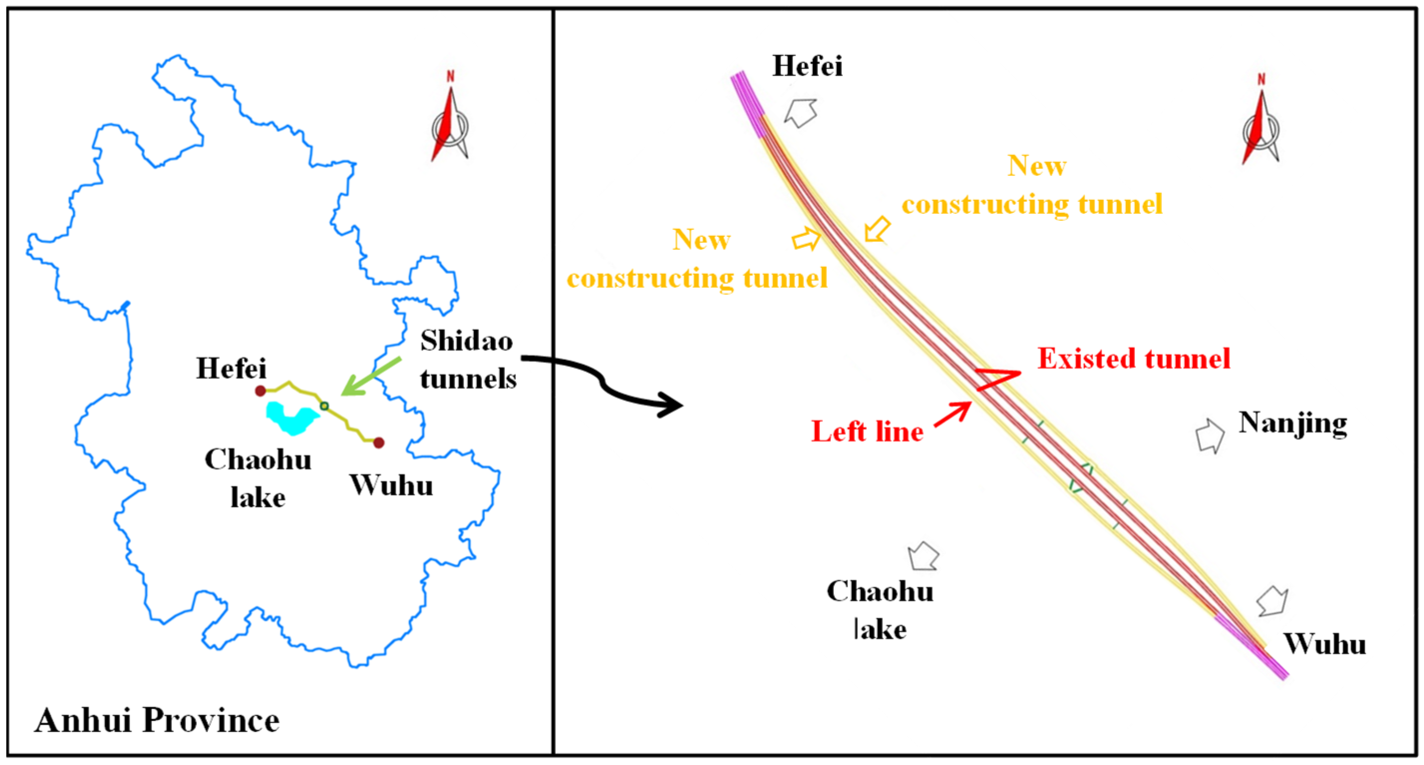
2.1. Expansion Project Site for Shidao Tunnels

Shidao tunnels are twin tunnels and located at the east of Chaohu lake, Anhui province in eastern China. The tunnels are the critical nodes of the expressway connecting two cities of Hefei and Wuhu, as shown in Figure 1. The existed tunnels were constructed and put into operation since 1996. The two-lane expressway could not meet the requirement of the rapid increasing traffic, so an expansion project of Shidao tunnels was planned. Two new tunnels marked by yellow lines were decided to be built outside of the existed twin tunnels, which are presented in red lines in Figure 1. The lengths of the left line and right line of the new constructing tunnel are 1220 m and 1230 m respectively. Horizontal spacing between the new constructing tunnel and the existed one is 38.2 m approximately. Due to the symmetry of these two lines, the left line is selected to be studied in the study.

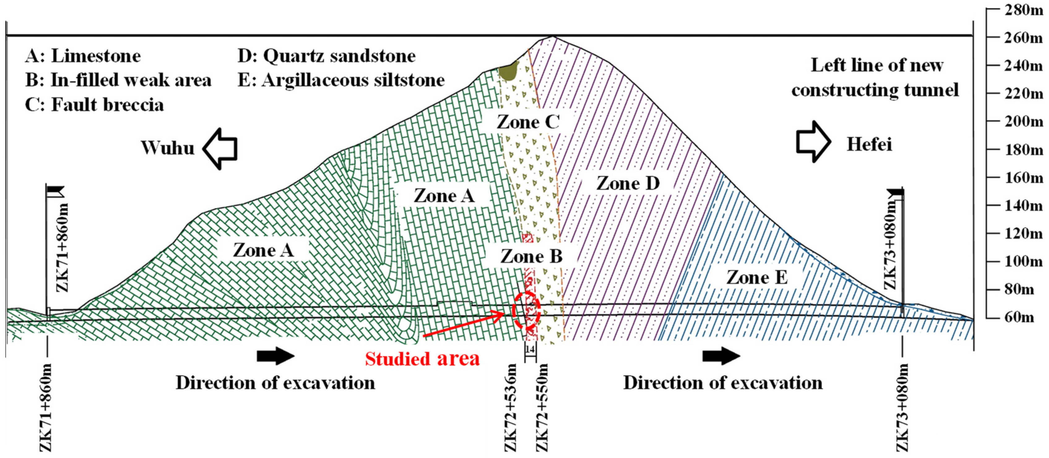
2.2. Geological Profile of Expansion Project for Shidao Tunnels

The main geological profile of the left line of the new constructing tunnel, as shown in Figure 2, is mainly composed of five main rock strata, of which the weak area is zone B. The filling of the weak area is perfectly round limestone block mixed up with silt and its total length is about 14 m, from ZK 72 + 536 m to ZK 72 + 550 m. Therefore, it is necessary to focus on this area during the excavation. For other four zones, zone A is between ZK 71 + 860 m and ZK 72 + 536 m, zone C is between ZK 72 + 550 m and ZK 72 + 591 m, zone D is between ZK 72 + 591 m and ZK 72 + 744 m, and zone E is between ZK 72 + 744 m and ZK 73 + 080 m.

2.3. Excavation and Constructing Procedures

Zone A is composed of relatively complete and high-quality limestone, so the tunnel is excavated by drilling and blasting method and bench cut method. When close to zone B (ZK 72 + 530 m), altering with center diaphragm (CD) method, the new tunnel is excavated, which can reduce the rock disturbance caused by excavation and is suitable for large-span tunnels in weak surrounding rocks [33]. The excavation surface is divided into four parts. Each part is excavated by small mechanical or hand in sequence and supported with primary lining, bolts, and temporary middle wall. After a proper excavating interval of 4~5 m, the temporary middle wall is removed and then the second lining and inverted arch are installed. Zones C, D, and E are also excavated by drilling and blasting method and bench cut method because of the relatively good properties of rock strata in the three zones.

3. Field Investigations on New Constructing and Existed Tunnels

In order to obtain the geological conditions of surrounding rock, the quick and high-precision acquisitions on the excavation surfaces of the new constructing tunnel are applied and the geological parameters of the surrounding rock are obtained. Meanwhile, the displacement of the vault and the side wall of the new constructing and existed tunnels in the studied area between ZK 72 + 530 m and ZK 72 + 550 m are measured in real-time during the constructing process, as shown in Figure 3. Four represented cross sections at ZK 72 + 536 m, ZK 72 + 540 m, ZK 72 + 544 m, and ZK 72 + 548 m marked by cross sections I, II, III, and IV are selected to study the influence of constructing a new tunnel on an existed tunnel. Meanwhile, real-time monitoring on the development of a longitudinal crack identified from the existed tunnel is conducted, which is representative of and adjacent to the studied area.

3.1. High-Precision Acquisitions on Excavation Surfaces of New Constructing Tunnel

After emerging of the excavation surfaces, the geological information of the rock mass such as integrity condition is measured by the high-precision acquisitions, which are binocular photogrammetry and 3D laser scanning [21,22,23]. The discontinuities are extracted by the automatic methods to determine the volumetric joint counts of excavation surfaces based on the 3D point cloud data. The surface condition of discontinuities including roughness, weathering, and infilling are obtained by field observation and geological sketch. Since the studied area contains zone A and zone B, the geological conditions of rock mass in both two zones are investigated separately. According to Sonmez and Ulusay [34,35], GSI of zone A and zone B can be determined based on the structure rating (SR) for integrity condition and surface condition rating (SCR) for surface condition of discontinuities. The values of each parameter and GSI of zone A and zone B are listed in Table 1.
The new constructing tunnel is excavated using CD method in the studied area, so each time the excavation surface is small. Moreover, small mechanical excavation, sometimes with hand excavation, is used to bring minimal disturbance to the surrounding rock mass during excavation. According to the method proposed by Hoek et al. [36], the disturbance parameter D is 0. Based on the disturbance parameter D and GSI, the modulus Em can be calculated using the empirical formula proposed by Hoek et al. [36], which can be expressed as
For rock mass, when σci ≤ 100 MPa,
E m = ( 1 D / 2 ) σ c i / 100 10 ( GSI 10 ) / 40
when σci > 100 MPa,
E m = ( 1 D / 2 ) 10 ( GSI 10 ) / 40
On-site load test is conducted and the uniaxial compressive strength (UCS) of rock can be obtained. For zone A, from ZK 72 + 530 m to ZK 72 + 536 m, UCS is 44.5 MPa, and for zone B, from ZK 72 + 536 m to ZK 72 + 550 m, UCS is 20.4 MPa. UCS of surrounding rocks in zone A and zone B are both less than 100 MPa, so Em of these two types surrounding rocks can be determined from Equation (1) and are 2.1095 GPa and 0.6023 GPa respectively. The surrounding rock in zone A contains medium weathered limestone, marl, and partly calcareous shale, which is fractured and medium-hard, while zone B is perfectly round limestone block mixed up with silt, and the content of the block stone is about 80%. According to Hoek and Brown [28], Marinos and Hoek [37], the H-B parameter mi of zone A is 7, and that of zone B is 6. The parameters of the surrounding rock such as gravity density ρ, Poisson’s ratio v, UCS, and so on are listed in Table 2.

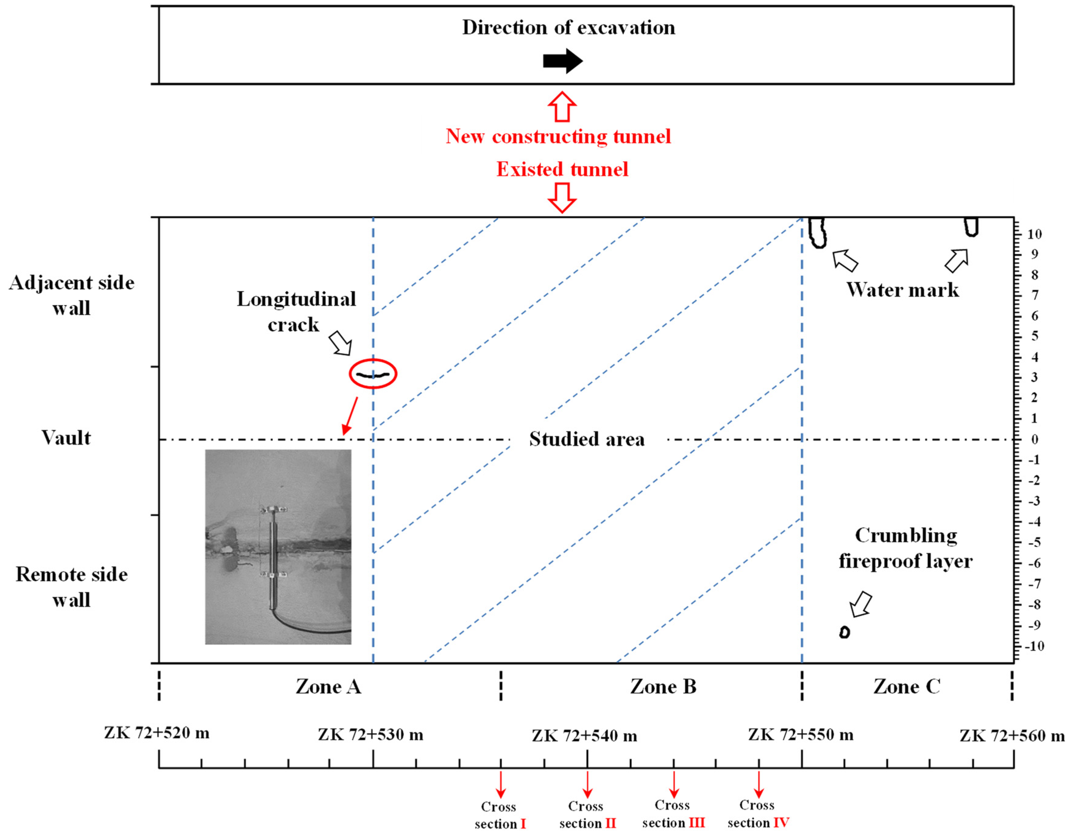
3.2. Real-Time Monitoring Development of Crack in Existed Tunnel

The existed tunnels had been completed for almost 20 years when the new tunnel was constructed. The apparent image and outline characteristics of the existed tunnel lining are collected through the automatic detection equipment. By identifying the apparent defect information, it is found that there are water marks, a crumbling fireproof layer, and a longitudinal crack in the existed tunnel between ZK 72 + 520 m and ZK 72 + 560 m, as shown in Figure 3. It is worth noting that the longitudinal crack is located at ZK 72 + 530 m, which is close to the in-filing weak area zone B and may be greatly affected by the excavation of zone B. Therefore, the variations of this crack width are measured by deformation strain gauge during the excavation of the new constructing tunnel, especially when zone B is excavated.

4. Numerical Study on New Constructing and Existed Tunnels

Numerical model is developed and used to simulate the excavating process of the new constructing tunnel. The results of the numerical simulation are compared with the real-time monitoring data. The performance of new constructing tunnel and the effect of a new constructing tunnel on existed tunnel are then studied using the numerical model.

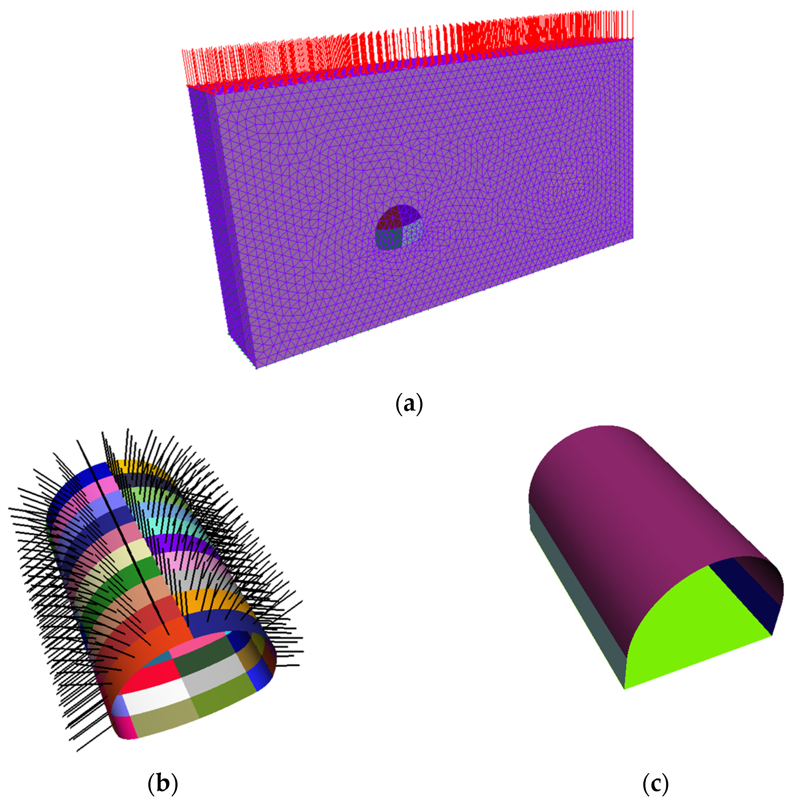
4.1. Numerical Model of Surrounding Rock and Tunnels

The parameters of the surrounding rock have been obtained by field investigations in Section 3.1. The sizes of numerical model and material properties of support structures are determined with reference to the project profile. Then, a numerical model is developed and the constructing process of new tunnel is simulated.

4.1.1. Overview of Numerical Model

Since the symmetry of the Shidao tunnels, the new constructing and existed tunnels of lift line are selected for numerical analysis. The longitudinal length of the numerical model is 20 m of the studied area. In order to simplify modeling and calculation process, the plane sizes of tunnels model and rock mass model are determined, as shown in Figure 4. New constructing tunnel has the vertical size of and horizontal size of 10.24 m and 12.62 m, while that of the existed tunnel is 9.48 m and 12.74 m respectively. The distance between these two tunnels is 38.22 m. The dimension of the rock mass on the right side of existed tunnel is 19 m, half of the distance between the two existed tunnels, and on the left side and the upper side of new constructing tunnel are both 30 m.
The modified GZZ constitutive model is applied in surrounding rock and parameters of the surrounding rock are shown in Table 2. It is worth mentioning that the buried depth of new constructing tunnel is approximately 175 m and there are only 30 m high rock mass considered in the numerical model. As a consequence, the weights of remaining 145 m high rock mass in two zones need to be applied to the upper surface of zone A and zone B uniformly, which are 3930.80 kN/m2 and 3930.62 kN/m2 respectively. The numerical model is established using GeoFBA3D, a 3D finite element code, with triangular mesh. All four sides are applied normal displacement constraints, and bottom surface is applied three-direction displacement and rotation constraints.
Moreover, the support structures of both new constructing and existed tunnels are considered in numerical model. The supporting structures of the existed tunnel include primary lining, secondary lining, and inverted arch, while that of the new constructing tunnel include primary lining, secondary lining, inverted arch, and bolts. For bolts, the length is 3.5 m, and the diameter is 25 mm. The vertical and longitudinal spacing is 2 m. The material properties of support structures are presented in Table 3.

4.1.2. Numerical Simulation of Excavating Process

The new tunnel is constructed using CD method and the total length of excavation simulated is 20 m, with two meters per excavation. During the excavating process, the longitudinal distances between part I and part II is 2 m, between part II and part III is 6 m, and that between part III and part IV is 2 m. The excavating process of the existed tunnel is not considered, which means that the 20 m long excavation existed and primary lining, secondary lining, and inverted arch of existed tunnel are installed initially in the numerical model. After that, from the first construction step, the excavation of new constructing tunnel starts. For new constructing tunnel, inverted arch is applied in step 52, 66, and 74, and secondary lining is applied in step 74. The relationship between the excavation distance, mileage of part IV, and construction step is shown in Table 4. Figure 5 and Figure 6 present the primary support of each part under the excavating process of the new tunnel, the meshed numerical model, and the support structures of the new constructing and existed tunnels.

4.2. Numerical Analysis on Performance of New Constructing Tunnel

The horizontal convergence displacement of the side walls by real-time monitoring are compared with the numerical analysis results to validate the numerical study. Then the performance of the new constructing tunnel, which is vertical displacement of the vault and horizontal displacement of the adjacent side wall selected from four represented cross sections, is analyzed in the entire excavating process. Plastic zone of cross section at ZK 72 + 550 m is studied with regard to the constructing influence of the four divided parts on the excavation surface.

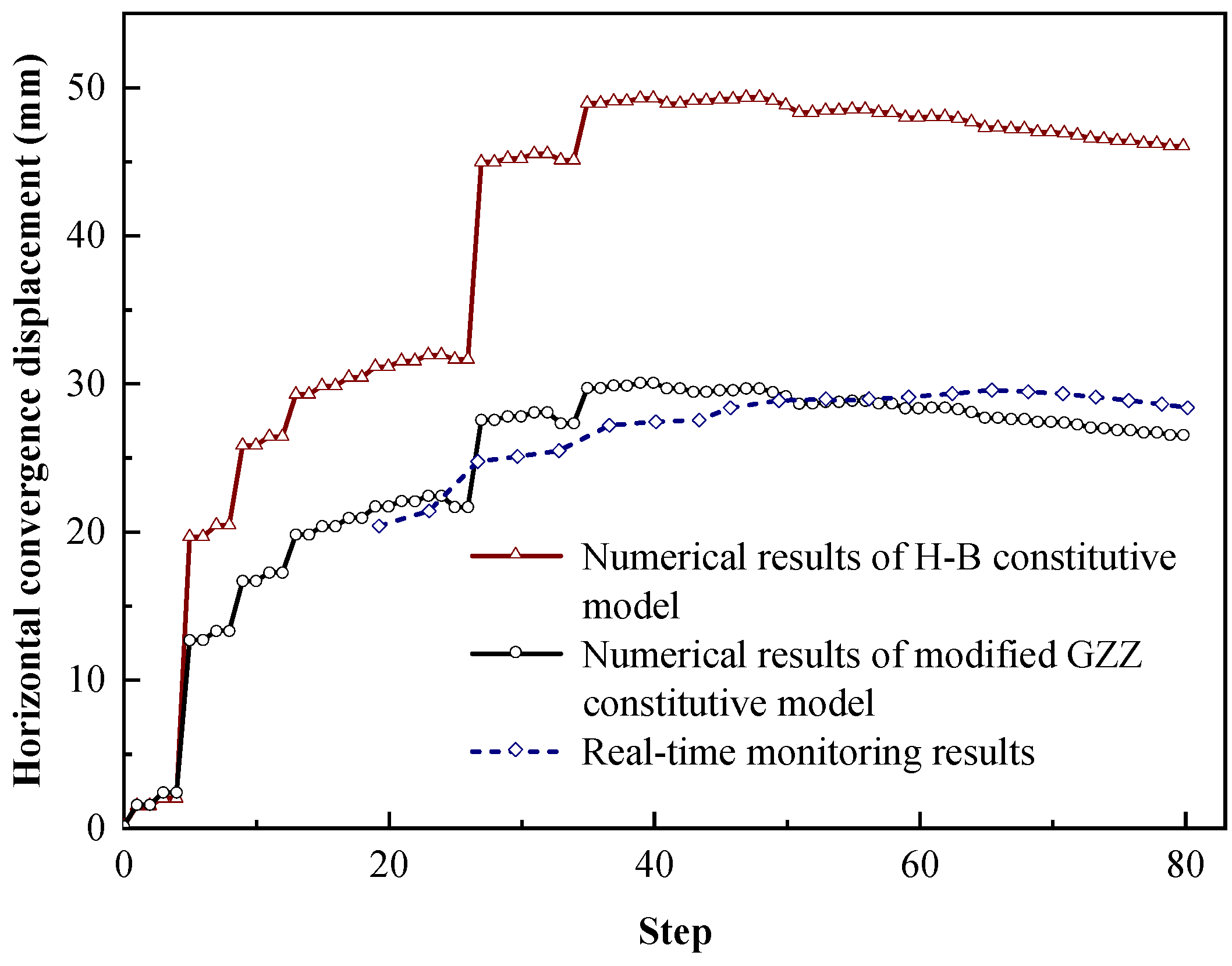
4.2.1. Validation of Horizontal Convergence Displacement of Side Walls by Real-Time Monitoring at ZK 72 + 530 m

The horizontal convergence displacement of the side walls of new constructing tunnel at ZK 72 + 530 m is selected as the index to validate the numerical study. After the excavation and initial support of part III, real-time monitoring is conducted using a displacement gauge (JSS30A). The real-time monitoring displacements are compared with the numerical results using modified GZZ constitutive model and H-B constitutive model, as shown in Figure 7. It is obvious that the numerical analysis result of modified GZZ constitutive model is closer to real-time monitoring results. The numerical analysis result of H-B constitutive model is approximately twice as large as that of modified GZZ constitutive model. The main reason for this difference is that the H-B strength criterion does not account for the effect of intermediate principal stress, which might affect the strength of the rock mass and, as a result, the accuracy of H-B constitutive model [29,31,32]. In detail, the final horizontal convergence displacement obtained by numerical analysis based on H-B constitutive model is 46.0 mm, and that based on modified GZZ constitutive model is 26.5 mm.

4.2.2. Vertical Displacement of Vault and Horizontal Displacement of Adjacent Side Wall

Vertical displacement of the vault and horizontal displacement of the adjacent side wall of cross section I, II, III, and IV are obtained by numerical analysis, as shown in Figure 8. The variations of displacement during the entire constructing process are investigated. In the early period of excavation, while the surrounding rock has just begun to be weakened, the contour of new constructing tunnel is squeezed inwards under the surrounding rock stress. Then the existed tunnel begins to deform approaching the weakened surrounding rock of zone B, which leads to both vertical displacement of the vault and horizontal displacement of the adjacent side wall of new constructing tunnel to be negative. Continuous excavation results in a substantial weakening of the surrounding rock in zone B with poor geological condition, which makes vertical displacement of the vault of new constructing tunnel increase rapidly at this stage in Figure 8a. The surrounding rock of adjacent side of the new constructing tunnel is squeezed outwards due to the settlement of the surrounding rock at the vault. This resulted in the horizontal displacement of the adjacent side wall of new constructing tunnel has a slight rebound at last stage, as illustrated in Figure 8b, which is because of the redistribution of stress field of surrounding rock.

4.2.3. Plastic Zone of Cross Section at ZK 72 + 550 m

The developments of plastic zone of cross section at ZK 72 + 550 m before being excavated to being completely excavated are illustrated in Figure 9, and the right side of new constructing tunnel is the adjacent side close to existed tunnel. In step 43, the plastic zone does not appear, and the previous excavation does not cause plastic failure to the surrounding rock. When the excavation surface gradually approaches the cross section, the plastic zone appears in part I and II and mainly concentrated in part I in Figure 9b. Then, part I of the cross section is excavated in step 54, the plastic zone is further expanded, overlying part II of rock mass in Figure 9c. In step 60, part II of the cross section is excavated, then the plastic zone on both sides is enlarged, overlying part III and IV of rock mass in Figure 9d. In step 76, Part III of the cross section is excavated, then the plastic zone on the left and top decreases slightly, and the plastic zone extends to the right side close to the existed tunnel in Figure 9e. After the last part IV of the cross section excavated, the symmetrical plastic zone is found on the periphery of tunnel contour except for the vault, and the plastic zone of the adjacent side is slightly larger, as shown in Figure 9f. The eventual range of plastic zone is less than 20% horizontal size of the new constructing tunnel, which indicates the divided excavation method can obviously reduce the constructing influence in weak rock mass.

4.3. Numerical Analysis on Effect of New Constructing Tunnel on Existed Tunnel

During the excavating process, the longitudinal crack of existed tunnel located at ZK 72 + 530 m is conducted by real-time monitoring. Based on the numerical analysis, the width variation of longitudinal crack is validated by the real-time monitoring results. Then vertical displacement of vault, and horizontal displacement of the adjacent side wall of existed tunnel are extracted at four represented cross sections to study the effect of new constructing tunnel on existed tunnel numerically.

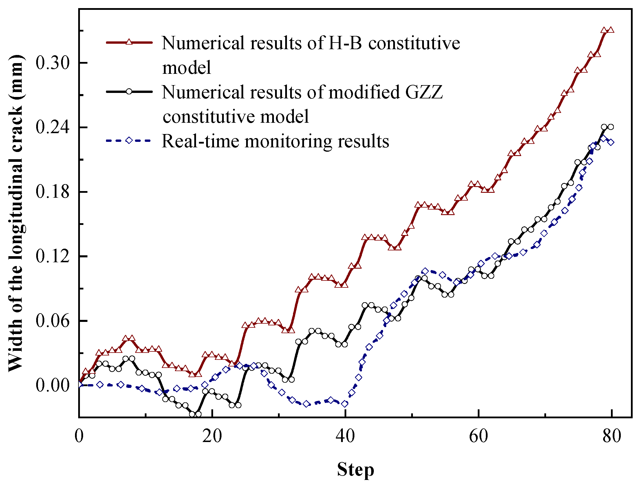
4.3.1. Validation of Width Variation of Longitudinal Crack in Existed Tunnel

The numerical analysis was carried out using modified GZZ constitutive model and H-B constitutive model respectively. The vertical deformation differential between two nodes adjacent to the crack is defined as the width variation of this longitudinal crack. The width of the longitudinal crack is measured in real-time as introduced in Section 3.2. The results of both numerical analysis and real-time monitoring are illustrated in Figure 10. Since further expansion of the existed crack requires overcoming the tensile strength of the lining, it can be seen that there is a buffer stage at the beginning of excavation during which the crack width remains almost constant. In addition, in contrast to numerical analysis result, the real-time monitoring result has a certain lag effect in the early period of excavation. This is because the deformation of the surrounding rock and the change of the stress field caused by excavation of new tunnel will take some time, rather than be affected immediately as numerical simulation. In the later period of excavation, the modified GZZ constitutive model well reflected the width development of the longitudinal crack compared with that of H-B constitutive model.

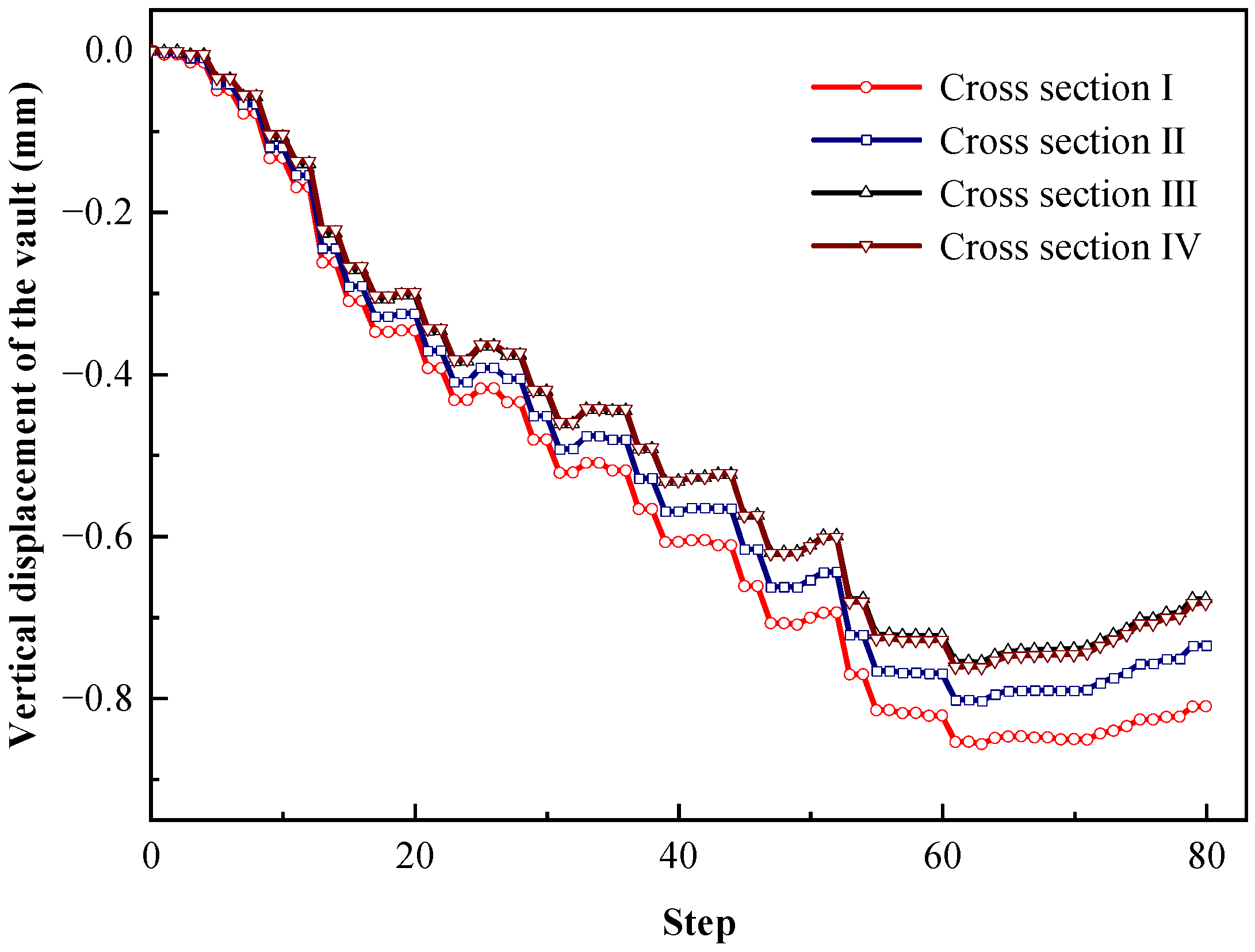
4.3.2. Vertical Displacement of Vault of Existed Tunnel

The vertical displacement of the vault at cross section I, II, III, and IV of existed tunnel is presented in Figure 11. The developed trends of the four cross sections are remarkably similar, and their values are also not much different. The maximum difference of is 0.15 mm. Due to the excavation of different parts of new constructing tunnel, it is shown that the displacement has a certain degree of fluctuation during the constructing process, but has no influence on the overall trend. In detail, vertical displacements of the vault of four cross sections increase in the early period of construction, and then reach the maximum near the same construction step 60. Among them, the value of cross section I is the largest, which is approximately −0.88 mm. At the end of construction, the vertical displacement of the vault slightly rebounded. Taking the cross section IV as an example, the final rebound of the vertical displacement of the vault is about 0.08 mm. This is related to the horizontal displacement of the adjacent side wall of new constructing tunnel, which also has an induced rebound as shown in Figure 8b.

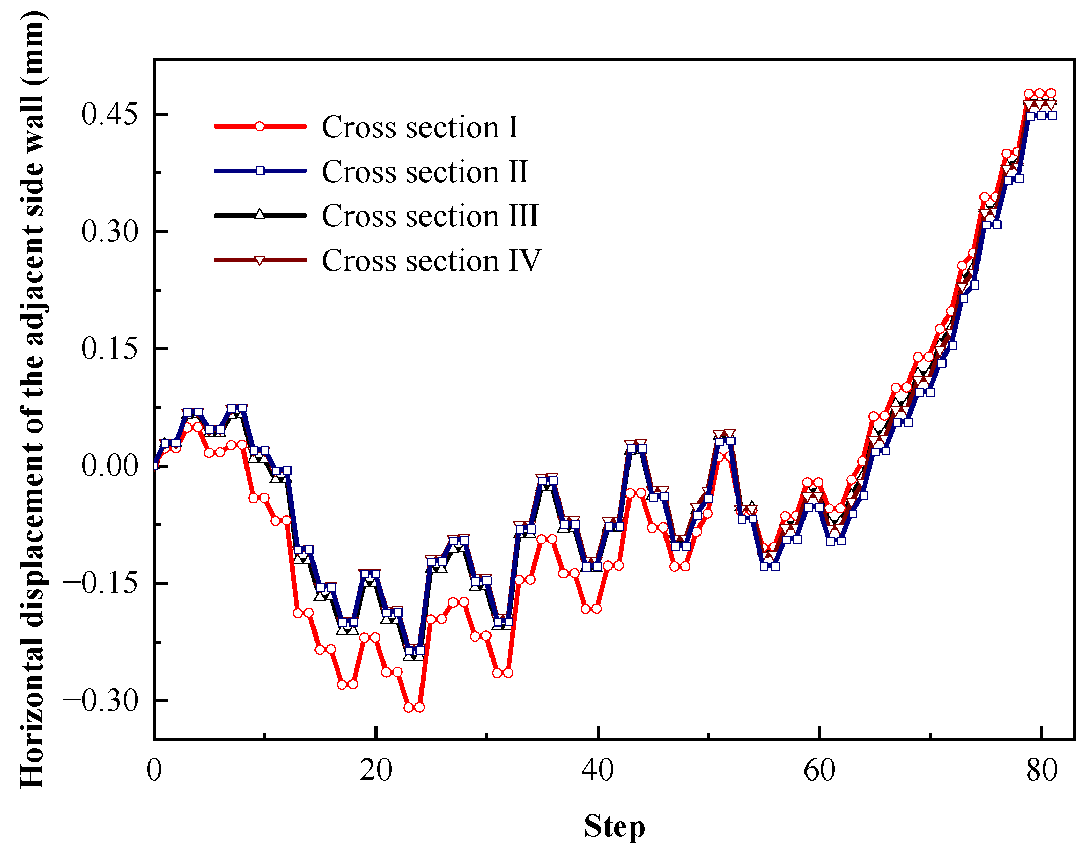
4.3.3. Horizontal Displacement of Adjacent Side Wall of Existed Tunnel

Figure 12 shows the horizontal displacement of the adjacent side wall of existed tunnel at cross section I, II, III, and IV. The horizontal displacements for these four cross sections are also not much different and the maximum difference is 0.08 mm. A slight reverse displacement occurs at step 60, this is because of the influence of the redistribution of the stress field caused by the new tunnel excavation. It is found that the displacements all decrease in early stage and then rebound to a positive increasing. Take cross section I as an example, the maximum negative and positive horizontal displacements of the adjacent side wall are about −0.3 mm and 0.48 mm respectively. The main reason is that the changes in the surrounding rock of the new tunnel affected the surrounding rock of existed tunnel during the constructing process. The surrounding rock of adjacent side wall of existed tunnel deforms in the direction of the new constructing tunnel first, and then rebounds due to the extrusion of the surrounding rock in the vault of new constructing tunnel.

5. Numerical Analysis on Constructing Influence of Tunnel Spacing and Geological Condition

A further parametric study is conducted based on the numerical model using modified GZZ constitutive model. The effects of tunnel spacing and geological condition of surrounding rock mass, which is represented by GSI, are analyzed.

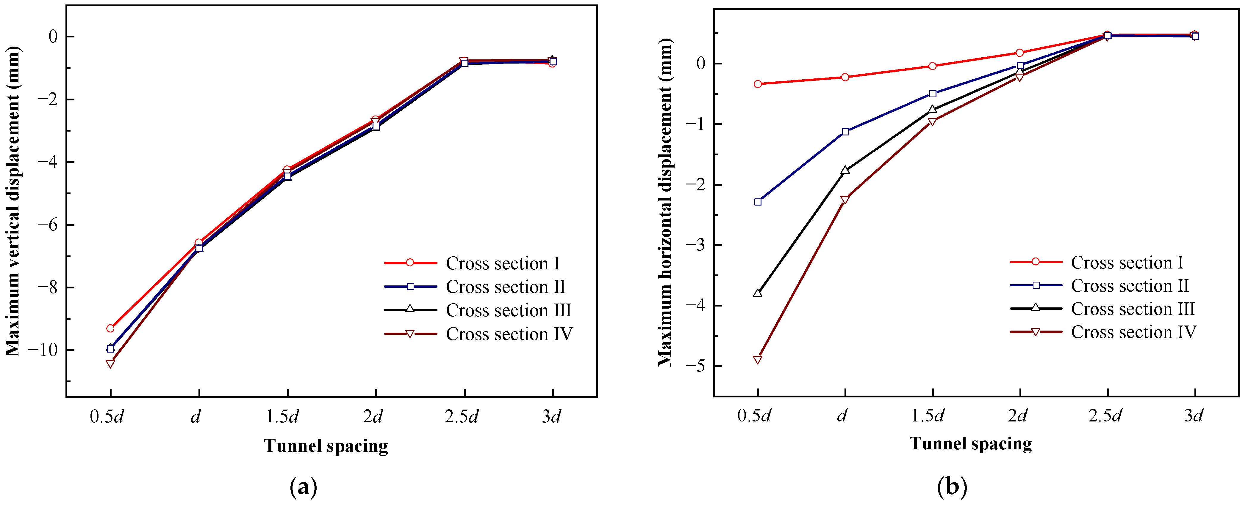
5.1. Spacing between New Constructing Tunnel and Existed Tunnel

The effect of the spacing between the new constructing tunnel and existed tunnel is discussed. Six kinds of tunnel spacing are considered, which are 0.5 d, 1 d, 1.5 d, 2 d, 2.5 d, and 3 d ( d is the actual spacing between the new constructing tunnel and the existed tunnel). During the excavating process, the maximum vertical displacements of the vault and the maximum horizontal displacement of the adjacent side wall at cross section I, II, III, and IV of the existed tunnel under various tunnel spacing are shown in Figure 13.
Figure 13a presents the relationship between tunnel spacing and maximum vertical displacement of the vault. It is obvious that the developed trends of maximum vertical displacements of the vault at four cross sections are very similar, and their values are also not much different. When tunnel spacing is less than 2.5 d, the maximum vertical displacements of the vault increase rapidly with decreasing of tunnel spacing. However, maximum vertical displacement of the vault is almost the same when tunnel spacing is 2.5 d and 3 d. Maximum vertical displacement reaches a peak at a tunnel spacing of 0.5 d, the value at cross section IV is the largest and the value is −10.4 mm, which is 1.2 mm larger than that at cross section I.
The development of maximum horizontal displacement of the adjacent side wall as the tunnel spacing changes is illustrated in Figure 13b. When tunnel spacing is less than 2.5 d, the maximum horizontal displacements of the adjacent side wall of four cross sections are close. Similarly, the maximum horizontal displacement of the adjacent side wall is almost constant when the tunnel spacing is not less than 2.5 d. When tunnel spacing is 0.5 d, the horizontal displacement of the adjacent side wall reaches a peak. The value at cross section IV is the largest, that is −4.9 mm, while that at cross section I is just −0.4 mm. In general, it can be conducted that as the tunnel spacing decreases, the impact of the excavation of new constructing tunnel on existed tunnel becomes more significant. As for the large differences observed in maximum horizontal displacement of the adjacent side wall at four cross sections, it is due to the different locations of the cross sections. For the existed tunnel, the final horizontal displacements of the adjacent side wall at four cross sections follow the same trend as the new constructing tunnel. The cross section with the largest displacement has the least rebound, which ultimately leads to the large difference in the maximum horizontal displacement of the adjacent side wall at different cross sections.

5.2. Geological Strength Index of Surrounding Rock Mass

Geological conditions can be evaluated quantitatively using GSI. In order to investigate the influence of different geological conditions, four GSI of zone B are discussed in this section which are 15, 20, 25, and 30, respectively and the geological parameters of zone A remain unchanged. The maximum vertical displacement of the vault and the maximum horizontal displacement of the adjacent side wall for the existed tunnel are shown in Figure 14.
There is no obvious difference between these four cross sections of both maximum vertical displacement of the vault and maximum horizontal displacement of the adjacent side wall. The maximum difference is less than 0.1 mm. Compared to small GSI values, the maximum vertical displacement of the vault in large GSI is decreased, which implies less vertical displacement of the vault occurs in the existed tunnel when the new tunnel is constructed in well geological conditions. However, the maximum horizontal displacement of the adjacent side wall has a slight increase when the geological conditions get better. In the cross section IV, when GSI is changed from 15 to 30, the maximum vertical displacement of the vault is reduced by about 0.15 mm, but the maximum horizontal displacement of the adjacent side wall is increased about 0.1 mm. The reason for that is the weakening in rebound of the adjacent side wall of the new constructing tunnel in the later period of excavation. Under well surrounding rock, the excavation will not cause obvious weakening of the surrounding rock. Therefore, the rebound of horizontal displacement of the adjacent side wall of the new constructing tunnel decreases and that of existed tunnel decreases correspondingly. This leads to the fact that though geological condition is better, the maximum horizontal displacement of the adjacent side wall of the existed tunnel increases slightly.

6. Summary and Conclusions

In this study, the geological conditions of the new constructing tunnel are obtained by high-precision observations and the width of a horizontal crack in the existed tunnel is real-time monitored. The monitored results are applied to verify the numerical analysis based on the modified GZZ constitutive model. The performance of new constructing tunnel and the effect of constructing a new tunnel on existed tunnel are analyzed by numerical model. The effects of the tunnel spacing and the geological condition of GSI are investigated.
  • The numerical analysis results based on modified GZZ constitutive model are in good agreement with real-time monitoring results. In new constructing tunnel, the vertical displacement of the vault keeps increasing in the constructing process. The horizontal displacement of the adjacent side wall has a slight rebound at last stage. This is due to the settlement of the surrounding rock at the vault, which squeezes outward the surrounding rock on the adjacent side of the new constructing tunnel. The development of the plastic zone of cross section at ZK 72 + 550 m of the new constructing tunnel indicates the divided excavation method can obviously reduce the constructing influence in weak rock mass.
  • The monitoring results show that the maximum width variation of the longitudinal crack in the existed tunnel is less than 0.3 mm during the constructing process of the new tunnel. Numerical analysis shows that the maximum vertical displacement of vault is less than 1 mm, and the maximum horizontal displacement of the adjacent side wall is less than 0.5 mm. The numerical analysis indicates that the vertical displacement of the vault and the horizontal displacement of the side wall of existed tunnel show varying degrees of rebound in the later period of excavation. The main reason is that in the constructing process the redistribution of stress field causes the rock at its adjacent side wall to be squeezed and deformed toward the existed tunnel.
  • Tunnel spacing between the new constructing and existed tunnels has an obvious influence on the maximum vertical displacements of the vault and the maximum horizontal displacement of the adjacent side wall of the existed tunnel. When the distance is larger than 2.5 d, the influence on existed tunnel because of excavation is not remarkable, while the effect increases rapidly with its decrease when it is less than 2 d. Therefore, it is suggested that new constructing tunnels should be kept at least 2 d away from the existed tunnel, so that the influence of excavation can be minimized. In general, poor geological conditions lead to an increase in the constructing effect of the new constructing tunnel on the existed tunnel. Therefore, it is suggested to strengthen the support of the surrounding rock when constructing a new tunnel in the weak rock mass.
This study can provide a practical experience and reference for the construction of new constructing side-by-side tunnels. The tunnel spacing between the new constructing and existed tunnels and the geological conditions have been demonstrated to have significant influence on the existed tunnel in this study. This impact might be mitigated by improving the support structure of the surrounding rock, which requires further investigations.

Author Contributions

Conceptualization, Q.Z.; methodology, T.Y. and X.G.; software, X.L.; validation, X.G.; formal analysis, T.Y.; investigation, X.G.; resources, X.L.; data curation, Y.S.; writing—original draft preparation, T.Y. and X.G.; writing—review and editing, Q.Z.; visualization, Y.S.; supervision, Q.Z.; project administration, Q.Z.; funding acquisition, Q.Z. and X.L. All authors have read and agreed to the published version of the manuscript.

Funding

This study was funded by the National Natural Science Foundation of China, grant number 41972277 and 41602300; the State Key Laboratory for GeoMechanics and Deep Underground Engineering, China University of Mining and Technology, grant number SKLGDUEK2006.

Data Availability Statement

Not applicable.

Conflicts of Interest

The authors declare no conflict of interest.

References

  1. Index No. 000019713O04/2022-00119; Statistical Bulletin on the Development of the Transport Industry in 2021. Ministry of Transport of the People’s Republic of China: Beijing, China, 2022.
  2. Li, X.G.; Yuan, D.J. Response of a double-decked metro tunnel to shield driving of twin closely under-crossing tunnels. Tunn. Undergr. Space Technol. 2012, 28, 18–30. [Google Scholar] [CrossRef]
  3. Do, N.A.; Dias, D.; Oreste, P. 3D numerical investigation of mechanized twin tunnels in soft ground—Influence of lagging distance between two tunnel faces. Eng. Struct. 2016, 109, 117–125. [Google Scholar] [CrossRef]
  4. Trinh, N.Q.; Holmøy, K.H.; Wiig, H.E. Challenging infrastructure project assisted by monitoring and numerical modelling as the follo line tunnels were excavated below existing tunnels. Rock Mech. Rock Eng. 2021, 54, 1671–1685. [Google Scholar] [CrossRef]
  5. Bauduin, C.; Kirstein, A.A. Design, construction and monitoring of an underwater retaining wall close to an existing immersed tunnel. Tunn. Undergr. Space Technol. 2022, 120, 104311. [Google Scholar] [CrossRef]
  6. Lv, J.; Lin, D.; Wu, W.; Huang, J.; Li, Z.; Fu, H.; Li, H. Mechanical responses of slurry shield underpassing existing bridge piles in upper-soft and lower-hard composite strata. Buildings 2022, 12, 1000. [Google Scholar] [CrossRef]
  7. Li, J.; Fang, Q.; Liu, X.; Du, J.; Wang, G.; Wang, J. Mechanical behaviors of existing large-diameter tunnel induced by horseshoe-shaped undercrossing twin tunnels in Gravel. Appl. Sci. 2022, 12, 7344. [Google Scholar] [CrossRef]
  8. Jin, D.; Yuan, D.; Ng, Y.C.H.; Pan, Y. Effect of an undercrossing tunnel excavation on an existing tunnel considering nonlinear soil-tunnel interaction. Tunn. Undergr. Space Technol. 2022, 130, 104571. [Google Scholar] [CrossRef]
  9. Charles, W.W.; Wong, Y.Y.A.; Shakeel, M. Effects of the skew angle of new tunneling on an existing tunnel: Three-dimensional centrifuge and numerical modeling. Can. Geotech. J. 2022, 59, 1728–1742. [Google Scholar]
  10. Fu, J.; Zhao, N.; Qu, Y.; Yang, J.; Wang, S. Effects of twin tunnel undercrossing excavation on the operational high speed railway tunnel with ballastless track. Tunn. Undergr. Space Technol. 2022, 124, 104470. [Google Scholar] [CrossRef]
  11. Gan, X.; Yu, J.; Gong, X.; Liu, N.; Zheng, D. Behaviours of existing shield tunnels due to tunnelling underneath considering asymmetric ground settlements. Undergr. Space 2022, 7, 882–897. [Google Scholar] [CrossRef]
  12. Sharifzadeh, M.; Tarifard, A.; Moridi, M.A. Time-dependent behavior of tunnel lining in weak rock mass based on displacement back analysis method. Tunn. Undergr. Space Technol. 2013, 38, 348–356. [Google Scholar] [CrossRef]
  13. Paltrinieri, E.; Sandrone, F.; Dudt, J.P.; Zhao, J. Probabilistic simulations of TBM tunnelling in highly fractured and faulted rocks. Tunn. Undergr. Space Technol. 2016, 57, 183–194. [Google Scholar] [CrossRef]
  14. Abdollahi, M.S.; Najafi, M.; Bafghi, A.Y.; Marji, M.F. A 3D numerical model to determine suitable reinforcement strategies for passing TBM through a fault zone, a case study: Safaroud water transmission tunnel, Iran. Tunn. Undergr. Space Technol. 2019, 88, 186–199. [Google Scholar] [CrossRef]
  15. Sharafat, A.; Tanoli, W.A.; Raptis, G.; Seo, J.W. Controlled blasting in underground construction: A case study of a tunnel plug demolition in the Neelum Jhelum hydroelectric project. Tunn. Undergr. Space Technol. 2019, 93, 103098. [Google Scholar] [CrossRef]
  16. Wang, F.; Zhou, M.; Zhang, D.; Huang, H.; Chapman, D. Random evolution of multiple cracks and associated mechanical behaviors of segmental tunnel linings using a multiscale modeling method. Tunn. Undergr. Space Technol. 2019, 90, 220–230. [Google Scholar] [CrossRef]
  17. Iasiello, C.; Guerra, T.; Juan, C.; Torrero Fernández, C. Large deformations in deep tunnels excavated in weak rocks: Study on Y-Basque high-speed railway tunnels in northern Spain. Undergr. Space 2021, 6, 636–649. [Google Scholar] [CrossRef]
  18. Luo, Y.; Chen, J.; Chen, Y.; Diao, P.; Qiao, X. Longitudinal deformation profile of a tunnel in weak rock mass by using the back analysis method. Tunn. Undergr. Space Technol. 2018, 71, 478–493. [Google Scholar] [CrossRef]
  19. Sakcali, A.; Yavuz, H. Estimation of radial deformations around circular tunnels in weak rock masses through numerical modelling. Int. J. Rock Mech. Min. Sci. 2019, 123, 104092. [Google Scholar] [CrossRef]
  20. Deng, H.; Fu, H.; Shi, Y.; Zhao, Y.; Hou, W. Countermeasures against large deformation of deep-buried soft rock tunnels in areas with high geostress: A case study. Tunn. Undergr. Space Technol. 2022, 119, 104238. [Google Scholar] [CrossRef]
  21. Zhu, H.H.; Wu, W.; Chen, J.; Ma, G.; Liu, X.; Zhuang, X. Integration of three dimensional discontinuous deformation analysis (DDA) with binocular photogrammetry for stability analysis of tunnels in blocky rockmass. Tunn. Undergr. Space Technol. 2016, 51, 30–40. [Google Scholar] [CrossRef]
  22. Chen, J.Q.; Zhu, H.H.; Li, X.J. Automatic extraction of discontinuity orientation from rock mass surface 3D point cloud. Comput. Geotech. 2016, 95, 18–31. [Google Scholar] [CrossRef]
  23. Li, X.; Chen, J.; Zhu, H. A new method for automated discontinuity trace mapping on rock mass 3D surface model. Comput. Geotech. 2016, 89, 118–131. [Google Scholar] [CrossRef]
  24. Li, X.; Chen, Z.; Chen, J.; Zhu, H.H. Automatic characterization of rock mass discontinuities using 3D point clouds. Eng. Struct. 2019, 259, 105131. [Google Scholar] [CrossRef]
  25. Zhang, L.Y.; Zhu, H.H. Three-dimensional Hoek-Brown strength criterion for rocks. J. Geotech. Geoenviron. Eng. 2007, 133, 1128–1135. [Google Scholar] [CrossRef]
  26. Hoek, E.; Brown, E.T. Empirical strength criterion for rock masses. J. Geotech. Engrg. Div. 1980, 106, 1013–1035. [Google Scholar] [CrossRef]
  27. Hoek, E.; Brown, E.T. The Hoek-Brown failure criterion: A 1988 update. In Proceedings of the 15th Canadian Rock Mechanics Symposium, University of Toronto, Toronto, ON, Canada, 3–4 October 1988; pp. 31–38. [Google Scholar]
  28. Hoek, E.; Brown, E.T. Practical estimates of rock mass strength. Int. J. Rock Mech. Min. Sci. Geomech. Abstr. 1997, 34, 1165–1186. [Google Scholar] [CrossRef]
  29. Zhang, L.Y. A generalized three-dimensional Hoek–Brown strength criterion. Rock Mech. Rock Eng. 2008, 41, 893–915. [Google Scholar] [CrossRef]
  30. Priest, S. Three-dimensional failure criteria based on the Hoek–Brown criterion. Rock Mech. Rock Eng. 2012, 45, 989–993. [Google Scholar] [CrossRef] [Green Version]
  31. Zhang, Q.; Zhu, H.H.; Zhang, L.Y. Modification of a generalized three-dimensional Hoek–Brown strength criterion. Int. J. Rock Mech. Min. Sci. 2013, 59, 80–96. [Google Scholar] [CrossRef]
  32. Zhu, H.H.; Zhang, Q.; Huang, B.Q.; Zhang, L.Y. A constitutive model based on the modified generalized three-dimensional Hoek–Brown strength criterion. Int. J. Rock Mech. Min. Sci. 2017, 98, 78–87. [Google Scholar] [CrossRef]
  33. Sharifzadeh, M.; Kolivand, F.; Ghorbani, M.; Yasrobi, S. Design of sequential excavation method for large span urban tunnels in soft ground–Niayesh tunnel. Tunn. Undergr. Space Technol. 2013, 35, 178–188. [Google Scholar] [CrossRef]
  34. Sonmez, H.; Ulusay, R. Modifications to the geological strength index (GSI) and their applicability to stability of slopes. Int. J. Rock Mech. Min. Sci. 1999, 36, 743–760. [Google Scholar] [CrossRef]
  35. Sonmez, H.; Ulusay, R. A discussion on the Hoek-Brown failure criterion and suggested modifications to the criterion verified by slope stability case studies. Yerbilimleri 2002, 26, 77–99. [Google Scholar]
  36. Hoek, E.; Carranza-Torres, C.; Corkum, B. Hoek-Brown failure criterion-2002 edition. In Proceedings of the Mining and Tunnelling Innovation and Opportunity: The 5th North American Rock Mechanics Symposium and 17th Tunnelling Association of Canada Conference, University of Toronto, Toronto, ON, Canada, 7–10 July 2002; pp. 267–273. [Google Scholar]
  37. Marinos, P.; Hoek, E. Estimating the geotechnical properties of heterogeneous rock masses such as flysch. Bull. Eng. Geol. Environ. 2001, 60, 85–92. [Google Scholar] [CrossRef]
Figure 1. Location of Shidao tunnels.
Buildings 12 01845 g001
Figure 2. Longitudinal section schematic of Shidao tunnels.
Buildings 12 01845 g002
Figure 3. Studied area of new constructing and existed tunnels.
Buildings 12 01845 g003
Figure 4. Cross-sectional diagram of rock mass model.
Buildings 12 01845 g004
Figure 5. Primary support under the excavating process. (a) part I (step 2); (b) part II (step 6); (c) part III (step 20); (d) part IV (step 28).
Buildings 12 01845 g005
Figure 6. Numerical model. (a) meshed tunnel model; (b) supporting structures of new constructing tunnel; (c) supporting structures of existed tunnel.
Buildings 12 01845 g006
Figure 7. Horizontal convergence displacement of side wall of new constructing tunnel at ZK 72 + 530 m.
Buildings 12 01845 g007
Figure 8. Displacement of new constructing tunnel. (a) Vertical displacement of the vault; (b) horizontal displacement of the adjacent side wall.
Buildings 12 01845 g008
Figure 9. Development of the plastic zone. (a) step 43; (b) step 46; (c) step 54; (d) step 60; (e) step 76; (f) step 80.
Buildings 12 01845 g009
Figure 10. Numerical analysis and real-time monitoring results of width of the longitudinal crack.
Buildings 12 01845 g010
Figure 11. Vertical displacements of the vault of existed tunnel.
Buildings 12 01845 g011
Figure 12. Horizontal displacement of the adjacent side wall of existed tunnel.
Buildings 12 01845 g012
Figure 13. Relationship between tunnel spacing and displacements. (a) Maximum vertical displacement of vault; (b) maximum horizontal displacement of adjacent side wall.
Buildings 12 01845 g013
Figure 14. Relationship between GSI and: (a) Maximum vertical displacement of vault, and (b) maximum horizontal displacement of the adjacent side wall.
Buildings 12 01845 g014
Table 1. Determination of GSI.
Surrounding
Rock
Structure Rating
(SR)
Roughness
(Rr)
Weathering
(Rw)
Infilling
(Rf)
Surface Condition Rating
(SCR = Rr + Rw + Rf)
GSI
Zone ABlocky
/Disturbed
Slightly roughModerate~Highly weatheredSoft
<5 mm
730
24322
Zone BDisintegratedSlickensidedHighly weatheredSoft
<5 mm
315
10012
Table 2. Parameters of surrounding rock.
Surrounding Rockρ (kg/m3)Em (GPa)vUCS (MPa)GSIDmi
Zone A 27002.10950.444.53007
Zone B 26600.60230.420.41506
Table 3. Material properties of support structures.
TunnelStructuresMaterialDensity (kg/m3)E (GPa)Poisson
Ratio v
Thickness
(cm)
Existed tunnelPrimary liningPlain concrete220025.50.2530
Secondary liningReinforced concrete250031.50.2550
Floor backfillingPlain concrete2400280.2570
New constructing tunnelPrimary liningPlain concrete220025.50.2526
Secondary liningReinforced concrete250031.50.2560
Floor backfillingPlain concrete2400280.2560
BoltsSteel78002100.25
Table 4. Excavating distance and mileage of part IV corresponding to each construction step.
Construction Step1~2627~3435~4243~5051~5859~6465~6869~7273~7677~7879~80
Excavation distance (m)02468101214161820
Mileage of part IV
[ZK (m)]
72 + 53072 + 53272 + 53472 + 53672 + 53872 + 54072 + 54272 + 54472 + 54672 + 54872 + 550
Publisher’s Note: MDPI stays neutral with regard to jurisdictional claims in published maps and institutional affiliations.

