Abstract
The thin-wall high-strength (HS) steel tube can provide strong confinement ability for core concrete due to its high yield strength, so it can achieve the purpose of confining concrete lateral deformation. In order to make full use of the mechanical properties of HS steel tube and concrete, it is necessary to study the axial compressive properties of the concrete-filled HS steel tube (CFHST) with a large diameter-to-thickness ratio (D/t). In this study, the axial compressive capacity of 15 CFHST columns with a large diameter-to-thickness ratio was tested. Then, a series of finite element (FE) models were developed to study the interaction mechanism between steel tube and concrete, the load–strain curves of typical specimens, and the effect of the key parameters. Finally, a new design proposal for CFHST compressive capacity is proposed and compared with EC4, GB50936-2014, and AIJ-97 prediction results. The results showed that the CFHST has good compressive capacity and can effectively confine the lateral deformation of core concrete; the contact pressure appears a stable stage because with a steel tube is difficult to effectively restrain the lateral deformation after steel tube yielding and partial failure of concrete; the existing design code is conservative in predicting the axial compression capacity of the CFHST with large D/t ratio.
1. Introduction
Concrete-filled steel tube (CFST) is one of the most widely used structural forms in Asian high-rise buildings, such as the Zhoushan power transmission tower in China (Figure 1), which makes full use of the properties of steel and concrete materials [1,2]. Under the action of external force, CFST can work together with mutual compensation. The filling of core concrete avoids premature partial yield of the steel tube, while the external steel tube brings effective confinement effect for the core concrete to improve its compressive capacity.
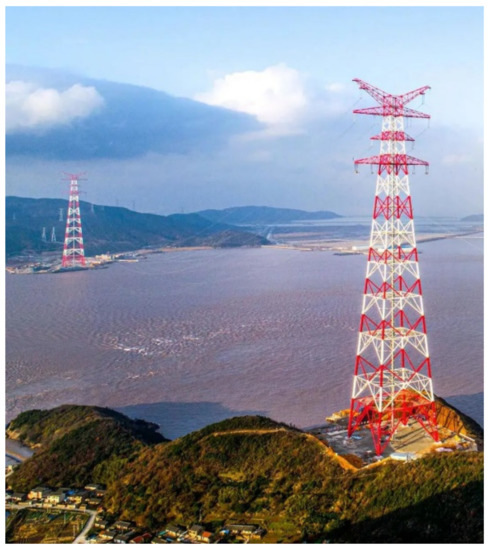
Figure 1.
Engineering application of CFHST.
With the improvement of the development level of high-strength (HS) steel, it has been gradually promoted and applied in CFST structures to enhance their compressive capacity [3,4]. Moreover, for concrete-filled high-strength steel tube (CFHST) structure, HS steel tube can provide a stronger confinement effect for core concrete than ordinary strength steel tube due to its high yield strength. The appearance of CFHSTs is beneficial to reducing the wall thickness of steel tubes and the cross-section size of components, thus improving the use efficiency and aesthetics of buildings.
In recent years, CFST structure forms have aroused the interest of scholars, and a series of studies have been carried out. Chen et al. [5] proposed two kinds of novel section forms of CFST without welding and established a design method by considering the stability of axial compressive capacity. Azevedo et al. [6] evaluated the circular recycled aggregate CFST stub columns under compression and concluded that the diameter-to-thickness (D/t) and the confinement effect coefficient directly influence the composite section response. Yu et al. [7] reported the global buckling behavior of concrete-filled wide rectangular steel tubular columns. Qiao et al. [8] tested the key parameters of concrete-filled stainless-carbon steel tube stub column, such as column section type, strength and wall thickness of carbon steel tube, and concrete strength.
For the mechanical behavior of CFHST under axial compression, Khan et al. [9] investigated the mechanical properties of a series of CFST stub columns made of high-strength materials with D/t ratios ranging from 15 to 40. Yan et al. [10] studied the axial compressive capacity of CFST using Q460 and Q620 HS steel tubes and showed that good ductility was observed in all specimens with confinement effect coefficients ranging from 1.41 to 5.27. Uy et al. [11] reported six CFHSTs to consider the influence of strength and ability. Sakino et al. [12] conducted 16 CFHST columns with HS steel tubes between 507 MPa and 853 MPa to study the mechanical behavior of centrally loaded columns. Aslani et al. [13] investigated the compressive behavior of CFHSTs, including concrete strength (21~55 MPa), depth-to-thickness ratio (16~40), and length-to-thickness ratio (2.60~2.85), and compared their results with relevant standards to calculate the compressive capacity. Liao et al. [14] poured different proportions of self-compacting concrete into an elliptical HS steel tube, from which the influence of key parameters on the compressive capacity of CFHST can be concluded. Wang et al. [15] reviewed the compressive behavior of circular CFHST stub columns and found that all specifications made conservative predictions about the strength capacity of circular CFST. Tu et al. [16] designed eight CFHST columns made of Q460 steel to investigate the axial compression performance by using experiment and FE modeling.
In the above studies, the axial compressive properties of concrete columns made from HS steel tubes with yield strength below 690 MPa were relatively comprehensive. However, there are few studies on CFST made of grade Q690, and the influence of the larger D/t ratio on the compressive behavior of CFHSTs has not been considered. The D/t ratio of CFST is strictly restricted in existing specifications, and the D/t ratios are not allowed to be greater than 28.5, 56.13, and 84 according to the limitation of EC4, GB 50936-2014, and AISC 360-16 [17,18,19,20]. But the thinness of the HS steel tube can satisfy the confinement of lateral deformation of core concrete due to its large yield strength. In addition, the axial compression capacity of CFHST predicted by existing design methods is conservative, which is not conducive to the rational use of this structure. Therefore, it is necessary to conduct an in-depth study on the axial compression performance of CFHST with a large D/t ratio and put forward a new design proposal for predicting the peak capacity of CFHST.
In this study, to investigate the effect of the D/t ratio on their axial compressive performance, 15 CFHST short columns were investigated by an axial compression test. Then, many different FE models were developed and verified by test results to study the failure mechanism of CFHST and the variation rule of N-ε curves with key parameters (concrete compressive strength, steel yield strength, D/t ratio, and confinement effect). Finally, a new CFHST design method is established and compared with the results of existing specifications.
2. Experimental Program and Results
2.1. Specimen Designs
In order to prevent the weakening of the confinement effect and support effect on the core concrete due to premature local buckling of the steel tube, the EC4, GB50936-2014, and AISC 360-16 codes limit the D/t ratio of CFST. However, this restriction in several codes may not apply to HS steel. Since Q690 HS steel has a higher yield strength compared to ordinary carbon steel, it can provide a stronger confinement effect to the core concrete. Hence, it is necessary to investigate the compressive behavior of CFHSTs with a large D/t ratio. The thin-walled HS steel was used, and the design of the D/t ratio far exceeded the limits of existing specifications to test the mechanical properties of CFHST in this structural form [17]. In this work, a total of 15 CFHST stub columns were subjected to uniaxial compression tests, and the D/t ratio varied from 60 to 130. In order to study the compressive performance of CFHST stub columns, it is necessary to control the length-to-diameter ratio of the columns so as not to exceed 4, and therefore, the length-to-diameter ratio of specimens was uniformly designed as 3.75. The designed parameters of CFHST stub columns are listed in Table 1, in which D, t, and L are respectively the diameter of the exterior steel tube, the thickness of the steel tube, and the length of CFHST stub columns.

Table 1.
Designed parameters of CFHST stub columns.
2.2. Test Materials
The CFHST columns were designed with a combination of HS steel Q690 and core concrete C50. To investigate the mechanical properties of materials, a series of mechanical tests were carried out. There were six coupons of different thickness steel in each group. The Q690 HS steel coupons were tested by a tensile testing machine with a displacement-controlled loading method. The failure modes of steel coupon are illustrated in Figure 2, and the typical stress-displacement curves are given in Figure 3. The yield strength, ultimate strength, elasticity modulus, and Poisson’s ratio are listed in Table 2. The elongation of Q690 HS steel is 16%, which meets the requirements of construction steel [21].
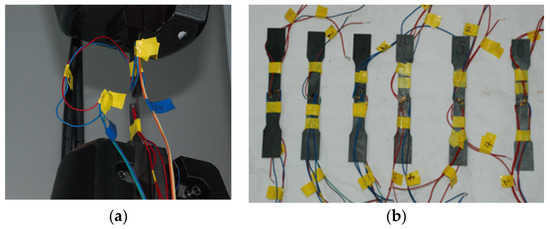
Figure 2.
Details of material properties test. (a) Loading process. (b) Tensile fracture of steel coupons.
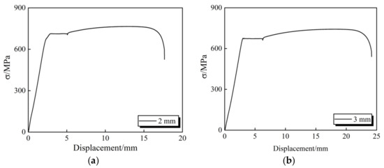
Figure 3.
The stress-displacement curve of steel coupons. (a) At 2 mm thickness. (b) At 3 mm thickness.
Table 2.
Test results of steel coupon.
The mechanical properties of core concrete were measured by a pressure testing machine, and the average cube compressive strength (fcu) was 50.4 MPa (size: 150 × 150 × 150 mm). The elastic modulus of the concrete prism (size: 150 × 150 × 300 mm) was 31,833 MPa, which is tested by multiple loading stages. The mix proportion of concrete is listed in Table 3. The maximum aggregate size of concrete was not more than 20 mm.
Table 3.
Mix proportion of concrete.
2.3. Test Setup and Loading Program
The compressive test loading device and measuring apparatus of the CFHST column were shown in Figure 4. To investigate the strain distribution along the steel tube, strain gauges were bonded to the surface of the steel tube. In addition, in order to measure lateral displacement, four displacement gauges were set in the middle of the specimen. The loading process was divided into two stages. The loading was controlled by vertical load in the initial stage, which increased 10% of the peak load (Pmax) at each step until 0.6 Pmax. After that, the loading was controlled by vertical displacement with an increment of 0.2 mm/min.
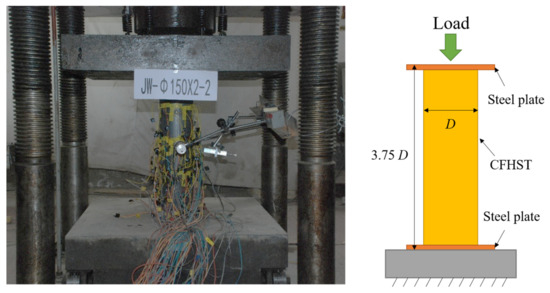
Figure 4.
Loading devices.
2.4. Axial Compression Test and Results
2.4.1. Failure Modes
Figure 5 describes the typical failure modes of different specimens under uniaxial compression. The failure mode of the CFHST stub column is mainly shear failure, which is because the local buckling of the steel tube weakens the confinement effect of the steel tube on concrete, resulting in brittle failure of concrete. The specimen with a different D/t ratio has a similar failure process until the steel tube yields; after that, a significant slip between the steel tube and the core concrete and a number of shear plane failures occurred. Finally, the specimen failed completely due to a local fracture of the steel.
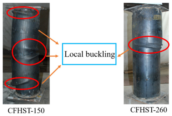
Figure 5.
Loading methods and boundary conditions of FEM.
2.4.2. Load–Displacement Curve
Figure 6 illustrates the load–displacement curves of different groups, and the D/t ratio is the key factor affecting the curve variation of each group. The compressive capacity of CFHST-140, CFHST-150, CFHST-180, CFHST-220, and CFHST-260 are 1564 kN, 2057 kN, 2330 kN, 3096 kN, and 4207 kN, respectively. With the decrease in steel tube wall thickness, the confinement effect of the steel tube on internal concrete is gradually weakened, so the compressive capacity begins to decline slowly after reaching the peak load.
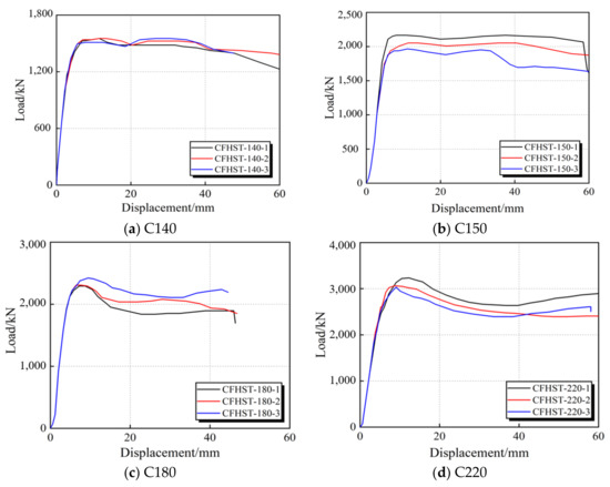
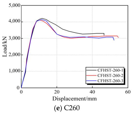
Figure 6.
Axial load–displacement response of tested specimens.
2.4.3. Load–Strain Curves
In Figure 7, the variation rule of external steel tube strain of each specimen with vertical load is drawn, where T and L respectively represent transverse strain and longitudinal strain. In the initial loading stage, the strain of the HS steel tube appears a good linear relationship with the vertical load. When the steel tube reaches yield strength, the vertical load of the CFHST rises slowly, but the strain value increases significantly. From the load–strain curves of each specimen in Figure 7 it can be concluded that the smallest diameter specimen has the best confinement effect on the core concrete.
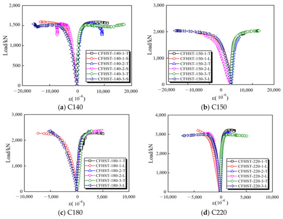
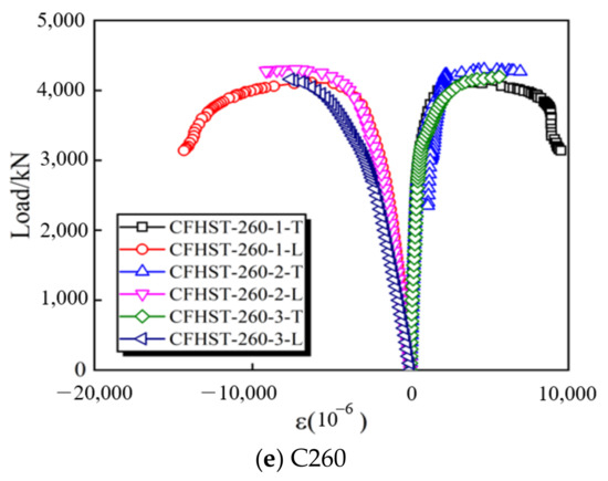
Figure 7.
Load–strain curves of CFHST specimens.
3. Finite Element Modelling and Verification
3.1. Finite Element Modelling
3.1.1. Simulation Method
To study the axial behavior of the CFHST stub column, a series of finite element (FE) models were explored and verified by experimental results. The three-dimensional solid continuum elements were applied in core concrete, which is a mesh type of eight-node isotropic 3D element with reduced integration (C3D8R). On the other hand, the mesh type of four-node isoperimetric shell elements with reduced integration (S4R) was used for the steel tube. In order to ensure the calculation accuracy and reduce the operation time, the mesh size was set as 20 mm.
To accurately model the interaction behavior, the Coulomb friction model and hard contact were applied in the tangential direction and the normal direction, respectively, in which the friction coefficient was taken as 0.6 by Han [22]. By using buckle mode analysis, the initial bending is applied to the FE model to better fit the actual conditions. In this study, the steel tubes were all fabricated by welding, and the effect of initial defects on the compressive capacity of CFHST columns was considered in the FE model.
3.1.2. Material Properties
- (1)
- Q690 high-strength steel
The constitutive materials of steel in the plastic area were described by three procedures, including isotropic, kinematic, and combined models in ABAQUS software. A trilinear isotropic model was adopted by defining the stress–strain data in yield point and peak point, where the slope of the post-yield stage was to be 0.01 Es. The yield strength and compressive strength are defined in Table 2. The elastic modulus and Poisson’s ratio were respectively defined as 210 GPa and 0.3.
- (2)
- Core concrete
The density, elastic modulus, and Poisson’s ratio of core concrete were assumed to be 2500 kg/m3, 31 GPa, and 0.2, respectively. To accurately simulate the damage expansion process of core concrete, the constitutive concrete damage plasticity (CDP) model is adopted in FE models. The compressive behavior of concrete was based on the relationship proposed by Han et al. [22]. The relationship models are as follows:
where fc represents the cylinder strength of concrete; Ac and As respectively indicate the cross-sectional areas of core concrete and steel tube; ζ is the confinement coefficient, and fck is the concrete prism compressive strength.
3.1.3. Loading Methods and Boundary Conditions
Figure 8 shows that a vertical displacement of 60 mm along the Z-axis applies the axial load, and the degrees of freedom of Ux, Uy, URx, URy, and URz were restricted at the top reference point RP-2. Meanwhile, to simulate the rigid support of specimens at the bottom plates, the bottom of FEM is fully fixed at the reference point RP-1.
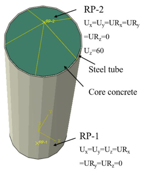
Figure 8.
Loading methods and boundary conditions of FEM.
3.2. Validation of FE Modelling
3.2.1. Failure Modes
Figure 9 gives the failure mode of FEM under plastic strain magnitude (PEMAG). The local buckling of C140 and C150 steel tubes is obvious, and the plastic deformation of the middle steel tube is also large. The samples C180, C220, and C260 have obvious lateral deformation and plastic deformation in the middle position. Compared with the failure mode of the experimental results, the local buckling deformation of the high-strength steel tube is clearly captured for FEM stub columns, and the number of waves and shape of failure are relatively close.
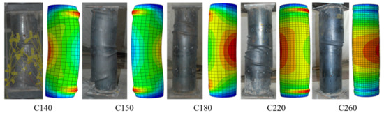
Figure 9.
Failure modes of CFHST stub columns.
3.2.2. Load–Displacement Curves and Axial Capacity
Figure 10 illustrates the results of the FE model validated by the experimental results of the CFHST stub column, and three replicates were carried out for each nominally identical model. Comparisons indicate very good consistency of the results in linear elastic as well as plastic regions, and the axial capacities of different FE models are similar to the experimental results. The linear region of the load–displacement curve is followed by a relatively gentle transition to the initial peak load, and then followed by plastic deformation with a slow drop in compressive capacity. Although the compressive capacity is significantly degraded after the first peak load, a large proportion of the load can be sustained. Table 4 gives a mean value of 0.99 with a COV of 0.001 by comparing with the results of the experiment and FE. To sum up, the comparisons of the load–displacement curves and the failure modes show a very good agreement with the results, ensuring a reliable FE model.
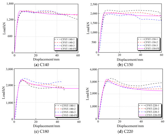
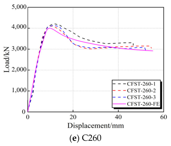
Figure 10.
The comparison between the results of FEMs and tested specimens.
Table 4.
Comparison between test results and FE results.
4. Analysis and Discussion
4.1. Compressive Behavior
In order to research the full range of axial compressive behavior of CFHSTs made with HS steel, the model CFHST-220-FE was taken as a typical analysis object to study the load–deformation relationship, and the interaction between steel tube and core concrete, including steel yield strength, concrete compressive strength, D/t ratio, and confinement effect. The column length is 3.75 times as long as the width. In addition, material modeling, interaction modeling, elements, and loading methods are consistent with Section 3.
Figure 11 gives the whole stress–strain history of model CFHST-220-FE, and the contribution of steel tube and core concrete to compressive capacity. The stress–strain curve can be divided into four stages by the stress state of steel tube and core concrete, which are the elastic stage (Points O–A), elastic-plastic stage (Points A–B), plastic stage (Points B–C), and softening stage (Points C–D). Point A is the yield point of the model CFHST-220-FE determined by Feng’s method [23]; Point B is the position where the steel reaches the yield load; Point C is the maximum stress point of the model CFHST-220-FE; Point D is selected when the axial strain is 40,000 με and the core concrete is considered to have completely failed. The Von Mises of steel tube and core concrete at different feature points are illustrated in Figure 12, and the relationship of contact pressure and vertical strain is given in Figure 13.
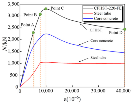
Figure 11.
N-ε curve.
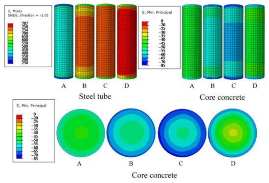
Figure 12.
The Von Mises stress of steel tube and core concrete.
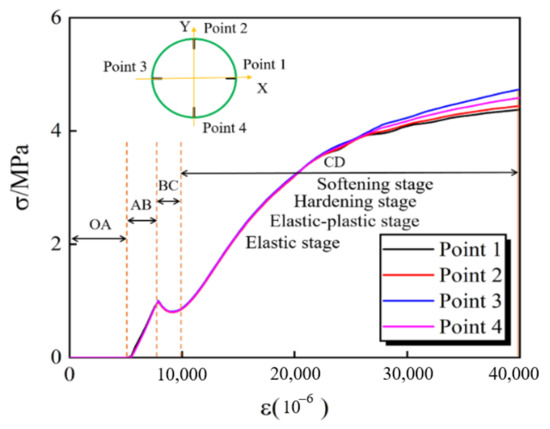
Figure 13.
The relationship between contact pressure and vertical strain.
Stage 1 (Points O–A): Elastic stage. At point A, the axial strain of the CFHST stub column is 7886 με. In this stage, the steel tube and core concrete mainly show elastic performance, and the stress–strain curve of the two materials approaches a straight line. It can be seen from Figure 13 that the contact pressure at the four positions is zero, indicating that the steel tube and core concrete bear the vertical load independently. At the end of this stage, the Von Mises stress of steel tube and core concrete are respectively in the ranges of 300~600 MPa and 35~50 MPa. Additionally, the steel tube and core concrete contribute 26% and 74% of the compressive capacity of the whole CFHST stub column. Meanwhile, the compressive capacity of core concrete is 121% of its uniaxial compressive capacity, and the compressive capacity of steel tube is 50% of its uniaxial compressive capacity.
Stage 2 (Points A–B): Elastic-plastic stage. At point B, the axial strain of the CFHST stub column reaches 7886 με. In the middle section along the length of the model, the local stress of the steel tube reaches the yield strength, and the core concrete shows obvious lateral deformation. In this stage, the contact pressure between the steel tube and concrete begins to appear and increases significantly by 0.92 MPa with the increase in strain value, indicating that the steel tube and concrete begin to bear the vertical load together. The Von Mises stress of steel tube and core concrete increases to the ranges of 500~750 MPa and 45~60 MPa at Point B; meanwhile, due to the accumulation of core concrete damage, the concrete load enhances slowly with the increase in strain value. At this time, the contribution of steel tubes and concrete to the compressive capacity is 33% and 67%, respectively. With the gradual yield of steel tubes, the contribution proportion of concrete to the compressive capacity begins to increase significantly.
Stage 3 (Points B–C): Hardening stage. The compressive capacity of the CFHST column reaches its peak at point C, at which point the concrete reaches its maximum compressive capacity and the steel tube completely enters the yield stage. The maximum compressive strength of core concrete can reach 73.25 MPa, which can be increased by 83.13% compared with the compressive strength of the uniaxial cylinder. At this stage, the contact pressure keeps a stable stage, which is caused by the fact that it is difficult to effectively confine the lateral deformation after steel tube yielding and partial failure of concrete. When the steel tube reaches the yield strength, a large lateral deformation of the steel tube occurs to the outside, although the lateral deformation of the core concrete develops slowly. It makes a small gap between the steel tube and the core concrete, and the contact pressure appears to drop during the hardening stage. Figure 12 illustrates that the Von Mises stress of steel tube and core concrete are respectively in the ranges of 600~787 MPa and 55~85 MPa. At the end of this stage, the contribution of steel tube and concrete to the compressive capacity is 32% and 68%, respectively.
Stage 4 (Points C–D): Softening stage. At this stage, since the plastic deformation of the steel tube increases significantly and the expansion of core concrete cracks, the compressive capacity of the CFHST column performs a stable decrease until it completely fails. Due to the uniform confinement of the external steel tube on core concrete, the stress of the concrete section increases gradually with the increase in radius. The steel tube and core concrete contribute 36% and 64% of the compressive capacity to the whole CFHST stub column at Point D due to the crushing failure of core concrete. Meanwhile, the Von Mises stress of steel tube and concrete increases to the ranges of 600~787 MPa and 50~65 MPa.
4.2. Numerical Parametric Studies
A series of comprehensive parametric studies were performed to investigate the influence of the D/t ratio, steel yield strength, compressive strength of concrete, and confinement effect coefficient on the strength of CFHST stub columns.
4.2.1. Effect of D/t Ratio
The effect of the D/t ratio on the axial compression performance of circular CFHST members was numerically studied. The D/t ratio of the outer tube is increased by changing the thickness of the tube, and the D/t ratio is considered to be in the range of 50~200. The N-ε curves of circular CFHST stub columns filled with C60 concrete and having various D/t ratios have been plotted in Figure 14a. As the D/t ratio increases, the peak load of the CFHST stub column is observed to be decreased and the post-peak compressive capacity degrades rapidly. Compared with model C1, the axial compressive capacity of models C2, C3, and C4 can be increased by 6.82%, 20.25%, and 62.06%, respectively. Although the reduction in the D/t ratio affects the degradation of peak capacity, the limit of the D/t ratio of CFHST still needs further discussion and determination.
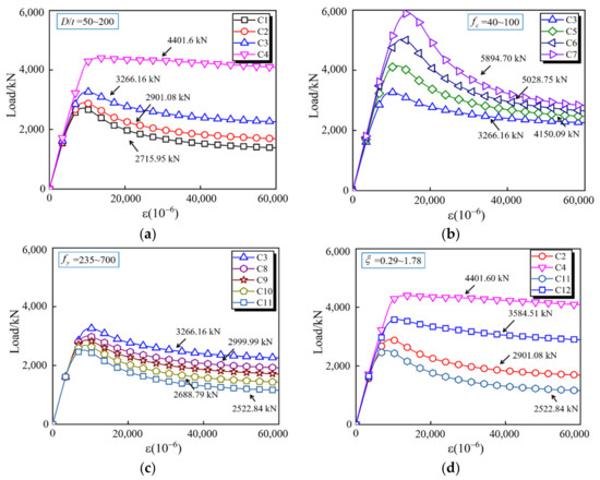
Figure 14.
N-ε curves of FE models. (a) Effects of D/t ratio. (b) Effects of compressive strength of concrete. (c) Effects of steel yield strength. (d) Effects of confinement effect coefficient.
4.2.2. Effect of Concrete Compressive Strength
Figure 14b gives the N-ε curves of different CFHST columns under axial compression by the effect of core concrete compressive strength. The FE models C3, C5, C6, and C7 listed in Table 5 are used to investigate the cylindrical compressive strength of core concrete, which varies from 40 MPa to 100 MPa. As the compressive strength of the concrete cylinder increases, the peak load increases by 27.06%, 53.97%, and 80.48%, respectively, compared with model C3. Moreover, the higher the compressive strength of the concrete cylinder, the more obvious the degradation of the post-peak load. Due to the high compressive strength of the core concrete, it is difficult for the HS steel tube to effectively confine the lateral deformation of the concrete.
Table 5.
Parameters of numerical models.
4.2.3. Effect of Steel Yield Strength
The effect of steel yield strength on the N-ε relationship of CFHST short columns is studied by numerical analysis in Figure 14c. The FE models C3, C8, C9, C10, and C11 listed in Table 5 are used to conduct numerical studies on the effect of steel yield strength, and the yield strength ranges from 235 MPa to 700 MPa. Compared with the C11 specimen with a yield strength of 235 MPa, the compressive capacity of short column specimens is increased by 6.58%, 13.43%, 18.91%, and 33.43%, respectively. Meanwhile, with the decrease in the yield strength of steel, the degradation trend of post-peak compressive capacity is gradually obvious.
4.2.4. Effect of Confinement Effect Coefficient
The constraint effect coefficient can reflect the confinement effect of external steel tubes on core concrete. It is mainly affected by four factors, namely steel yield strength, concrete compressive strength, steel tube sectional area, and core concrete sectional area, and its expression is shown in Equation (3). In order to study the influence of confinement effect coefficients on the axial compression performance of CFHST short columns, four models with different constraint effect coefficients are analyzed in Table 5, and their confinement effect coefficients are 0.29, 0.57, 1.12, and 1.78, respectively. As can be seen from Figure 14d, with the reduction in the constraint effect, the post-peak load of the N-ε curve gradually changes from rising to declining.
5. Evaluation of Existing Design Methods and Development of New Design Approaches
For the CFST made of low-strength carbon steel, the existing codes and design methods, such as those proposed by EC 4, GB 50936-2014, and AIJ-97, can predict the axial compression capacity roughly reasonably. However, the study and prediction of CFHST axial compressive capacity may not be accurate enough. Therefore, a new design method was developed based on the FE results and compared with the results of existing specifications and design methods to verify its accuracy.
5.1. Existing Design Methods
5.1.1. Eurocode 4 (EC4)
The European code EC4 proposed a design method for the axial compressive capacity of the CFST stub column. However, the strength of CFST specimens is limited, given that the yield strength of steel is less than 425 MPa, and the compressive strength of concrete is less than 50 MPa. The equations are as follows:
where fy, fc, and λ are the yield strength of steel tube, compressive strength of core concrete prism, and slenderness ratio.
5.1.2. GB 50936-2014
GB 50936-2014 specification is suitable for steel strength less than 420 MPa and concrete cube strength less than 60 MPa. The design equations are as follows:
where Asc is the cross-sectional area of concrete.
5.1.3. AIJ-97
The design method proposed by Japanese standard AIJ-97 to calculate the axial compressive capacity of the CFST column is as follows:
5.2. New Design Proposal
The yield strength of steel has a significant influence on the contact stress between steel tubes and core concrete. Therefore, the effective confining stress proposed by Liu et al. [24] is adopted. Because the effective confining stress overestimates the effective confinement effect of HS steel, this design method is only applicable to the CFST members. It needs to introduce the change coefficient of steel strength to modify the effective confining stress. Then, the result can be substituted into Mander’s model [25] of Equation (15) to obtain a more accurate axial compressive capacity of the confined concrete. The equations are described as follows:
where fr, fu, and fcc are respectively the effective confining stress, peak strength of steel tube, and the compressive strength of the confined concrete.
5.3. Comparison with the Existing Design Methods
The axial compressive capacity predicted by GB 50936-2014, EC4, and AIJ-97 standards or specifications is compared with the FE results, as shown in Table 6 and Figure 15. The red line in the middle represents the position where the average value is 1.00, and the black line on either side represents the boundary where the two results differ by 15%. It can be seen that the existing design methods have some deviations in predicting the compressive capacity of CFHST stub columns, and the prediction results obtained are relatively conservative. The predicted results of EC4, GB 50936-2014, and AIJ-97 are 10%, 3%, and 16% different from those of FE and experimental results, respectively. The average value of the new design proposal is 1.00 and the COV is 0.0049, thus proving the accuracy of the new design proposal.
Table 6.
Comparison with design method results.
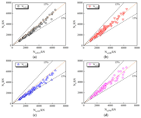
Figure 15.
Compared with the results of the experiment and FE. (a) Comparison of test and FE results with predicted results of EC4. (b) Comparison of test and FE results with predicted results of GB 50936-2014. (c) Comparison of test and FE results with predicted results of AIJ-97. (d) Comparison of test and FE results with predicted results of the new design proposal.
6. Conclusions
The axial compressive behavior of CFHST stub columns with a large D/t ratio was studied by means of experiment, FE model, and theoretical analysis, and the following conclusions are obtained:
- The failure mode of the CFHST stub column is mainly shear failure, which is because the local buckling of the steel tube weakens the confinement effect of the steel tube on concrete, resulting in brittle failure of concrete.
- The contact pressure shows an obvious stable stage at the BC stage of the CFHST column, which is because in the HS steel tube it is difficult to effectively confine the lateral deformation of concrete after yielding and local failure. At the end of this stage, the contributions of steel tube and concrete to the compressive capacity are 32% and 68%, respectively.
- The influence of key parameters on the axial compressive capacity of CFHST short columns is studied by numerical analysis, and the compressive strength of core concrete has the most obvious effect on the post-peak degradation of the N-ε curve. As the compressive strength of the concrete cylinder increases from 40 MPa to 100 MPa, the peak load increases by 80.48%.
- The accuracy of the new design proposal in predicting the peak load of CFHST short columns is verified by using 88 FE results and 15 test results, and it is proved that the peak load of CFHST columns predicted by the new design proposal, EC4, GB50936-2014, and AIJ-97 codes is conservative, with an average value of 1.00, 0.90, 0.97, and 0.84, respectively.
Author Contributions
Conceptualization, Z.Z. and P.T.; datacuration, J.W. (Jiantao Wang); formal analysis, J.W. (Jiaqi Wang) and Y.L.; funding acquisition, Z.Z. and Q.S.; investigation, J.W. (Jiaqi Wang); methodology, Y.W. and Y.L.; resources, Q.S.; software, Y.W.; validation, J.W. (Jiaqi Wang); supervision, Q.S.; writing-original draft preparation, Z.Z.; writing-review and editing, Z.Z. All authors have read and agreed to the published version of the manuscript.
Funding
This research was funded by the National Natural Science Foundation of China (Grant No. 51978570 and 52008228), basic scientific research operating expenses of Xi’an Jiaotong University (No. xzy022022040), Study on New Seismic Resistance System of High-rise Assembled Composite Structure (No. 20211177-ZKT09) and the Whole Life Cycle Design and Construction of Assembled Structure “Scientists + Engineers” Team (No. 2022KXJ-031). In addition, this study was supported by High-Performance Computing (HPC) Platform, Xi’an Jiaotong University.
Data Availability Statement
No applicable.
Conflicts of Interest
The authors declare no conflict of interest.
References
- Zhang, Z.; Wu, X.; Hu, G.; Sun, Q. Numerical study on triaxial compressive behavior of engineered cementitious composites confined by circular steel tubes. Constr. Build. Mater. 2022, 345, 128285. [Google Scholar] [CrossRef]
- Yu, P.; Ren, Z.; Yun, W.; Zhao, Y.; Xu, J. Performance of Bolt-Welded CFST Short Columns with Different Initial Imperfections: Experimental and Numerical Studies. Buildings 2022, 12, 1352. [Google Scholar] [CrossRef]
- Wang, Y.; Gao, S.; Xu, Y.; Li, F. Lateral Impact Response of Concrete-Filled Square Steel Tubes with Local Defects. Buildings 2022, 12, 996. [Google Scholar] [CrossRef]
- Chen, Z.; Dong, S.; Du, Y. Experimental study and numerical analysis on seismic performance of FRP confined high-strength rectangular concrete-filled steel tube columns. Thin-Walled Struct. 2021, 162, 107560. [Google Scholar] [CrossRef]
- Chen, Z.; Ning, F.; Song, C.; Liang, Y. Study on axial compression bearing capacity of novel concrete-filled square steel tube columns. J. Build. Eng. 2022, 51, 104298. [Google Scholar]
- Azevedo, V.; Lima, L.; Vellasco, P.; Tavares, M. Experimental investigation on recycled aggregate concrete filled steel tubular stub columns under axial compression. J. Constr. Steel Res. 2021, 187, 106930. [Google Scholar]
- Yu, C.; Tong, J.; Tong, G. Behavior and design of slender concrete-filled wide rectangular steel tubular columns under axial compression. Structures 2021, 33, 3137. [Google Scholar] [CrossRef]
- Qiao, Q.; Li, J.; Yang, Z.; Cao, W.; Yang, J.; Zhang, W. Axial compressive behavior of concrete filled stainless-carbon steel tube columns: Experimental investigation. J. Build. Eng. 2021, 42, 102460. [Google Scholar] [CrossRef]
- Khan, M.; Uy, B.; Tao, Z.; Mashiri, F. Concentrically loaded slender square hollow and composite columns incorporating high strength properties. Eng. Struct. 2017, 131, 69. [Google Scholar] [CrossRef]
- Yan, Y.; Xu, L.; Li, B.; Chi, Y.; Yu, M.; Zhou, K.; Song, Y. Axial behavior of ultra-high performance concrete (UHPC) filled stocky steel tubes with square sections. J. Constr. Steel Res. 2019, 158, 417. [Google Scholar] [CrossRef]
- Uy, B.; Mursi, M.; Tan, A. Strength of slender concrete filled columns fabricated with high strength structural steel. In ICASS ’02 Third International Conference on Advances in Steel Structures; Elsevier: Hong Kong, China, 2002; p. 575. [Google Scholar]
- Sakino, K.; Nakahara, H.; Morino, S.; Nishiyama, I. Behavior of centrally loaded concrete-filled steel-tube short columns. J. Struct. Eng. 2004, 130, 180. [Google Scholar] [CrossRef]
- Aslani, F.; Uy, B.; Tao, Z.; Mashiri, F. Behaviour and design of composite columns incorporating compact high-strength steel plates. J. Constr. Steel Res. 2015, 107, 94. [Google Scholar] [CrossRef]
- Liao, J.; Li, Y.; Yi, O.; Zeng, J. Axial compression tests on elliptical high strength steel tubes filled with self-compacting concrete of different mix proportions. J. Build. Eng. 2021, 40, 102678. [Google Scholar] [CrossRef]
- Wang, X.; Fan, F.; Lai, J. Strength behavior of circular concrete-filled steel tube stub columns under axial compression: A review. Constr. Build. Mater. 2022, 322, 126144. [Google Scholar] [CrossRef]
- Tu, C.; Shi, Y.; Dong, L.; Wang, W.; Ban, H. Behavior and general design method of concrete-filled high-strength steel tube (CFHST) columns. Eng. Struct. 2021, 243, 112506. [Google Scholar] [CrossRef]
- GB 50936-2014; Technical Code for Concrete Filled Steel Tubular Structures. China Building Industry Press: Beijing, China, 2014. (In Chinese)
- Eurocode 4, Design of Composite Steel and Concrete Structures-Part 1-1: General Rules and Rules for Buildings; European Committee for Standardization: Brussels, Belgium, 2004.
- ACI 318-05; Building Code Requirements for Structural Concrete and Commentary. American Concrete Institute: Farmington Hills, MI, USA; Detroit, MI, USA, 2005.
- AISC 360-16; Specification for Structural Steel Buildings. American Institute of Steel Construction: Chicago, IL, USA, 2016.
- GB/T 19879-2015; Steel Plate for Building Structure. China Building Industry Press: Beijing, China, 2015. (In Chinese)
- Han, L. Concrete Filled Steel Tubular Structures-Theory and Practice, 3rd ed.; Science Press: Beijing, China, 2016. (In Chinese) [Google Scholar]
- Feng, P.; Qiang, H.; Ye, L. Discussion and definition on yield points of materials, members and structures. Eng. Mech. 2017, 34, 36. (In Chinese) [Google Scholar]
- Liu, J.; Zhou, X. Behavior and strength of tubed RC stub columns under axial compression. J. Constr. Steel Res. 2010, 66, 28. [Google Scholar] [CrossRef]
- Mander, J.; Priestley, M.; Park, R. Theroetical stress-strain model for confined concrete. J. Struct. Eng. 1988, 114, 1804. [Google Scholar] [CrossRef]


Publisher’s Note: MDPI stays neutral with regard to jurisdictional claims in published maps and institutional affiliations. |
© 2022 by the authors. Licensee MDPI, Basel, Switzerland. This article is an open access article distributed under the terms and conditions of the Creative Commons Attribution (CC BY) license (https://creativecommons.org/licenses/by/4.0/).