Article

Research on Vibration Control of Power Transmission Lines-TMDI Based on Colliding Bodies Optimization

1
School of Civil Engineering and Architecture, Chongqing University of Science & Technology, Chongqing 401331, China
2
Chongqing Key Laboratory of Energy Engineering Mechanics & Disaster Prevention and Mitigation, Chongqing 401331, China
*
Author to whom correspondence should be addressed.
Buildings 2022, 12(12), 2200; https://doi.org/10.3390/buildings12122200
Submission received: 10 October 2022 / Revised: 5 December 2022 / Accepted: 8 December 2022 / Published: 12 December 2022
(This article belongs to the Special Issue Structural Vibration Control Research)

Abstract

:
To investigate the vibration control capability of a tuned mass damper inerter (TMDI) on a transmission line, the motion equations of the transmission line with TMDI under harmonic excitation were derived. Thus, the closed-form solutions of the displacement response spectrum were obtained by Fourier transform. Based on the colliding bodies optimization (CBO), one of the metaheuristic algorithms, the TMDI parameters, was optimized to minimize the displacement of the transmission line-TMDI system. The research results show that the response of the transmission line was reduced by at least half for different mass ratio and frequency ratio conditions, which indicates that the TMDI can effectively control the displacement response of the transmission line. In addition, the TMDI parameters were optimized by CBO, and the vibration control efficiency was significantly improved. The results of the study show that the data converge quickly with fewer iterations in collision body optimization. On the one hand, CBO avoids getting into local optimization compared to other metaheuristic algorithms. On the other hand, it is cheaper in terms of the cost of its calculations compared to the methods of mathematical derivation. It plays an active role in the optimization of complex structures. The vibration suppression performance of the TMDI after optimization reaches 56–96%.

1. Introduction

Based on electricity network security, more and more researchers are focusing on vibration control in transmission lines. Electricity is an important renewable and clean energy source, and it is becoming more and more important in this era. However, due to the uneven distribution of wind, tidal, and light energy resources, the use of natural resources for power generation is constrained by the geographical environment. The working environment of transmission lines is complex and changeable. Therefore, ensuring the safety of transmission lines cannot be ignored. In particular, the internal structure of transmission lines has very low damping, resulting in long and light transmission lines in the electricity network being particularly susceptible to wind, and being affected by wind-induced vibration for more than two-thirds of the year [1]. Breeze vibration has received attention from researchers. Breeze vibration is a high-frequency, low-amplitude harmonic vibration. Although the energy and amplitude of breeze vibration are small, smaller wind speeds can cause breeze vibration, and most lines are in breeze vibration for a longer period if vibration prevention measures are not taken. The use of traditional dampers, such as damping hammers, damping lines, spacer bars, and other control methods, has a significant impact on the transmission line. Transmission lines are prone to short circuits and apparatus damage, transmission line fatigue, tripping, and other failures. In particular, the internal fracture of a transmission line due to fatigue is difficult to observe and often found when an accident has occurred.
The wire is subjected to wind load and vibrates by the following principle: first, when the wind blows over the surface of the wire, it creates an air vortex coupled to the upper and lower surfaces of the transmission line. Then, the air vortex begins to fall off from the upper and lower surfaces of the transmission line in turn. Finally, an alternating force perpendicular to the direction of the incoming flow is generated to act on the transmission line, creating a periodic vibration response. In other words, vortex vibration is the basic component of wind vibration. This vortex is named the Kármán vortex, as shown in Figure 1. To control this form of vibration, which is very close to harmonic excitation, much research has been carried out by previous authors. Housner [2], a Japanese professor of engineering, introduced the idea of structural vibration management to reduce the vibration of structures in the 18th century, and in 1972, Professor Yao [3] applied modern control theory to the discipline of civil engineering. After about 47 years of research, many research ideas have been developed and often applied in real-world engineering. In electrical networks, structural vibration control [4] is the process of keeping the vibration response of a structure within reasonable limits. It is generally carried out by positioning devices and substructures to change or adjust the dynamic characteristics of the original structure. According to whether external energy is required, structural vibration control is divided into four categories: passive, active, hybrid, and semi-active control [5]. Active, hybrid, and semi-active control can add more energy to the controller and help it adapt to the system and the variety of different excitation forces. Compared to passive control, active control consumes more vibration energy, but the high efficiency of active control is based on the fact that it also requires a high amount of external energy of its own. However, due to the relatively high weight of the active control system, there is little redundancy in the installation area. Furthermore, in a harsh environment such as high-voltage transmission lines, the application of active control systems is not feasible, and simple passive control dampers are more beneficial.
In past decades, wind-induced vibration has been reduced or eliminated by employing various techniques, including structural, aerodynamic, and mechanical techniques. However, each technique has drawbacks and limitations. In 1988, Feldmann [6] studied in depth the nonlinearity of vibration-resisting hammers in breeze vibration. In 2011, Hou [7] reviewed the progress of transmission conductor and vibration-resisting hammer research while conducting an in-depth study on energy balance techniques and kinetic methods. When the line has been operating for a long time, the conductor self-damping characteristics and resonator damping characteristics tend to deteriorate, while the excessive mass of the resonator hammer produces a huge burden on the transmission line, as concluded by Zhang [8] in 1997. Scholars have made different attempts to control the vibration response of flexible cylindrical structures. Zhang [9] investigated the effect of using a nonlinear energy sink for vortex-induced vibration control of a flexible cylinder. However, for a flexible, light-weighted transmission line, sometimes it might be necessary to make the damper mass as low as possible due to economical and practical considerations. Among them, the vibration-damping effect of the antivibration hammer is proportional to its weight, and the heavier the suspension mass, the better the vibration-damping effect. Frahm [10] proposed a new type of damper called the tuned mass damper (TMD) in 1911. Huang and Tang [11] investigated the vibration control of pulsating wind response to large-span transmission tower structures by setting multiple annular TMDs. Song [12] used multiple-tuned mass dampers (MTMDs) to investigate the vibration control of a transmission tower-line system based on its constructional characteristics. To control the structure, Hongzhou [13] used a control scheme that combined TMDs and VEDs. The study’s findings revealed that the control device had varying degrees of control effects on the wire tension, tower top displacement, and acceleration, with a maximum reduction in response values of 10–20%. Chengzhong [14] used a bidirectional TMD for wind vibration control of transmission lines, and the results showed that the device was effective in controlling the displacement and acceleration response of the conductors, with in-plane and out-of-plane displacement control rates of 52.33% and 49.98%, respectively. On the other hand, many scholars have studied the TMD optimal parameter control theory. Bisegna and Caruso [15] used the transient response exponential decay rate to measure the performance of the TMD. Greco [16] suggested a displacement and energy-based criterion for the best TMD design and discovered that the energy criterion could greatly lessen the TMD system’s reaction. Zhang [17] used optimization involving the nonlinear aeroelastic effect to obtain the most economical TMD parameters. In 2002, Smith [18] introduced the concept of an inerter, using a mathematical model of capacitance to create an inertial container, which has the same dynamic properties in mechanics as capacitance in electricity [19]. It is widely used for damping control of vehicles, structures, cables, robot joints, etc. The ideal inertial container is a linear, massless, mechanical element with two endpoints, as shown in detail in Figure 2, where F is the output force, x ¨ 1 and x ¨ 2 are the accelerations of the two endpoints, and b is the scale factor of the difference between the output force and the accelerations of the two endpoints, commonly referred to as inertance, also known as apparent mass. The TMDI is a derivative of the TMD, which is a new type of damper consisting of a mass block, a spring, and an inertial device. In 2013, Marian and Giaralis [20] used a combination of an inerter in series with a TMD, as shown in Figure 2, called the tuned mass damper inerter (TMDI). It aims to use the inertial mass amplification effect of the inerter to reduce the mass block mass requirement of the TMD without diminishing its effectiveness of the TMD. Then, they [21] optimized the TMDI to reduce the displacement variance of the undamped single-degree-of-freedom system under white noise excitation, provided analytical solutions for the optimal TMDI parameters, and numerically analyzed the damping performance of the TMDI in the undamped and damped multi-degree-of-freedom. The numerical results revealed that the TMDI has better control performance than TMD.
The three forms of the TMDI are due to differences in inerter: rack–pinion inerter [22], ball–screw inerter [23], and hydraulic inerter [24], as shown in Figure 3. However, the more advanced ball–screw inerter and hydraulic inerter are more limited in the application scenario of transmission line vibration control. This is because high-voltage transmission lines can be in many adverse environments, such as significant temperature variations between day and night, conductor icing, and other arduous environments. Therefore, in this study, the rack–pinion inerter is used. The TMDI has recently attracted much interest in the fields of seismic and wind resistance of buildings and vibration-damping optimization. The seismic performance of foundation structures is enhanced using the TMDI features to increase the seismic capacity of buildings by De Domenico [25,26]. Pietrosanti [27] used a software system to analyze the seismic mitigation effect of the TMDI during a seismic yield increase. To study the control effect of the TMDI on the wind response of high-rise buildings under wind excitation, Giaralis [28] investigated the effect of the TMDI on the wind vibration of high-rise buildings by numerical simulation of 74-story building structures. The research of Giaralis [29] was based on the aerodynamic empirical power spectrum. Dai [30] studied the effect of the position of the inerter on a flexural TMDI structure under wind excitation performance under wind excitation and gave an empirical formulation for the ideal control system parameters. Zhang [31] proposed using a tuned mass-damper-inerter (TMDI) to mitigate edgewise blade vibrations in wind turbines. Lee [32] investigated the effect of the inerter location on the control performance of the TMDI in wind-induced vibration mitigation of flexible structures. It was shown that increasing the inertance of the inerter can effectively improve the high-mode damping effect of the TMDI, and optimizing the inerter location is more efficient for fundamental mode vibration mitigation. From these research results, the TMDI is significantly better than an antivibration hammer and TMD for structural vibration control. In particular, the TMDI is lighter in mass and places less burden on the wire, so using a TMDI to control the transmission line vibration response is beneficial to avoid a fatigue fracture effect inside the transmission line and prolong the service life of the transmission line. Undeniably, the difficulty of TMDI research is that the performance is very sensitive to its frequency ratio and damping ratio. Therefore, parameter optimization of the TMDI is the most urgent research area in the field of structural vibration control of transmission tower-line systems under wind loads.
An important part of the optimal design problem for the TMDI is the choice of the optimization method. An optimization procedure is generally required to determine the optimal TMDI parameters that enable the control target. In addition to the familiar range of mathematical methods, metaheuristic algorithms have emerged as the computing power of computers has grown rapidly. The metaheuristic algorithm is an intuitively or empirically constructed algorithm that computes the optimal solution to a problem over a specified range of values. For different data search strategies, metaheuristic algorithms are subdivided into many classes, such as genetic algorithms, annealing algorithms, artificial bee colony algorithms, collision body optimization, etc. Most engineering problems are partial differential equations or ordinary differential equations after simplification. However, purely theoretical mathematical derivations and metaheuristic algorithms have completely different ideas for solving optimal solutions. The fixed-point theory, first proposed by Hartog [33] in 1985, is used as an example. The method is based on the characteristics of the frequency response curve of the main structure, and the expression of the analytical solution of the optimal parameters of the damper under simple harmonic excitation is obtained by the Vieta theorem. Although the fixed-point-based optimization method can accurately capture the local optimal solution in the range of value domain, the cost of its calculations is very expensive. Furthermore, the fixed-point theory becomes more difficult to calculate as the complexity of the structure increases. Dong [34] used a revised fixed-point theory to study the variation law between dynamic parameters when sandwich-damped cantilever TMDs are coupled to each other and proposed a two-stage design method for decoupling. Li [35] proposed a new vibration-damping device, namely, the variable tuned mass damper inerter (VTMDI), and used fixed-point theory to systematically study its damping performance. Luo [36] used fixed-point theory to study the series viscous mass damper SVMD with optimized parameters and derived the structural response transfer function of SVMD. Ikago [37] proposed the tuned viscous mass damper (TVMD) based on an inerter and optimized its parameters using fixed-point theory. Barredo [38] used the fixed-point theory approach to obtain closed solutions for inerter-based dynamic vibration absorbers (IDVAs) and used numerical simulations and theoretical derivation methods to verify the analytical solutions. From these studies, some drawbacks of the fixed-point method were also exposed. On the one hand, the damping of the main structure is neglected in the engineering of the optimized dampers using the fixed-point method. On the other hand, in the optimization process of complex structures facing multiple degrees of freedom, it has been difficult to solve it using pure mathematics alone. To address this limitation, the metaheuristic algorithm has received attention from scholars at home and abroad, and many scholars have successfully applied it to solve various complex damper optimization problems. The optimization strategies of metaheuristic algorithms mostly simulate natural phenomena or physical laws and perform global searches in the range of values while mining local data through continuous iterations of the established strategies. Hadi and Arfiadi [39] used a genetic algorithm for the optimal design of a multi-degree-of-freedom damper. Febbo and Vera [40] used simulated annealing (SA) for the optimal design of a two-degree-of-freedom system. Bozer and Özsarıyıldız [41] used an artificial bee colony algorithm to obtain the optimal parameters of the MTMD. In 2014, the Iranian scholar Kaveh [42] simulated the process of object collision and proposed colliding body optimization (CBO). CBO is one of the metaheuristic algorithms. It uses a strategy that simulates the law of conservation of energy and the law of conservation of momentum to find the optimal solution. The data to be optimized is divided into two parts called moving body and stationary body, respectively. The optimization process is expressed as a moving body crashing into a stationary body and updating the position and velocity of the colliding body after the two parts collide. The collision process is repeated continuously so that the colliding body reaches the best position. CBO is capable of efficiently searching all data in the value range while maintaining a balance between the degree of global and local search. Compared with other metaheuristic algorithms, the collision optimization algorithm has fewer iterations of optimized solutions, faster convergence, and more stable data. Therefore, the CBO algorithm is more beneficial to solve the optimization problems of closed solutions of bivariate controlled displacement responses and closed solutions of uncontrolled responses. Therefore, CBO is more favorable for solving the problem of TMDI parameter optimization.
Due to the sensitivity of the TMDI to the damping ratio and frequency ratio, the control performance of the applied inerter depends on its parameters. Further analysis is needed to better evaluate the inerter enhancement effects and determine the optimal parameters. To address this problem, this paper conducts an analysis to evaluate the control performance of the TMDI subjected to harmonic excitations. Based on the Fourier transform approach, a closed-form solution is derived, and the control performance of the TMDI can be calculated quickly (Section 2). Next, in Section 3, based on the obtained formulas, the procedure of CBO determined the optimal design parameters (frequency ratio and damping ratio). Then, the inerter dependence analysis is carried out by comparing the control performance of the TMDI at different mass ratios and apparent mass ratios. A solution is proposed for a lightweight design of a damping device to adapt to different working conditions. This paper fills the gap in the optimization method of the TMDI in transmission line-TMDI systems, laying the foundation for subsequent studies that combine TMDI and damping lines in transmission line-TMDI systems.

2. Control Equations for Combined Transmission of the Wire-TMDI Systems

2.1. Movement in the PLANE of Transmission Wire

In this paper, the excitation force is from the fixed end of the wire h meters, the duration of t seconds is simplified as a concentrated load F n x , t , the nongrounded TMDI device is installed at the distance from the wire a, and the other end of the inerter is suspended from the wire a + g, and its mechanical analysis model is shown in Figure 4. Considering the physical properties of the inerter, the acceleration between the two ends of the inerter plays a positive role in the vibration suppression performance of the transmission line-TMDI system. Therefore, we expect the two ends of the TMDI to be suspended at the crest and trough of the nth vibration mode for the system.
Due to the special structure of the transmission conductor itself, there are problems such as mutual misalignment friction between the strand and the strand when the conductor vibrates; it is not possible to fully simulate the essential characteristics of the transmission conductor realistically, and it is more complicated to describe its dynamic characteristics. So, to facilitate the establishment of a mathematical model, the transmission conductor is subjected to the following basic assumptions in this paper.
(1) The transmission conductor span is a large gear distance. Its diameter is much smaller than the gear distance, and according to the self-limiting conductor, transmission conductor breeze vibration displacement usually does not exceed the transmission conductor diameter size. Therefore, it is assumed that the slope of the wire when the breeze vibration occurs is very small, i.e., the ratio of file distance to displacement amplitude is much less than 1 [43].
(2) In the mechanics of materials, it is pointed out that in the Euler–Bernoulli beam theory, for slender beams ( h / L 0 ), shear deformation can be ignored, and only bending deformation is considered. According to the description of the situation in (1), the transmission conductor cross-sectional bending moment can be expressed as E I 2 y / x 2 .
(3) Since the diameter of the transmission conductor always remains the same size, no change is found along the length direction with the tension deformation of the conductor. Therefore, it is assumed that the basic parameters such as unit mass and tension of the transmission conductor do not change with the length direction.
Based on the above assumptions, the transmission conductor can be simplified as a small-stiffness beam structure under tension. For the transmission conductor of suspension chain line type, the suspension points at both ends are regarded as hinged, and its microsegment force analysis is shown in Figure 5.
For the microsegment analysis, the equilibrium equation of the force in the y-direction and the equilibrium equation of the moment for point A are listed:
T B sin α B T A sin α A m 1 2 y x , t t 2 d x c 1 y x , t t d x Q x d x = F n x , t F 2 x , t d x M + M x d x M Q + Q x d x d x m 1 2 y x , t t 2 d x d x 2 + T B sin α B d x T B cos α B y x , t x d x = 0
tan α A = y x , t x tan α B = y x , t x + 2 y x , t 2 x d x T A = T cos α A T B = T cos α B M = E I 2 y x , t x 2 Q = M x = E I 3 y x , t x 3
where Q and M indicate the transmission conductor shear force and bending moment, respectively. Thus, bringing (2) into (1), the equation of motion of the transmission line-ungrounded TMDI under concentrated load can be expressed as:
m 1 y ¨ x , t + c 1 y ˙ x , t + E I y x , t T y x , t = F n x , t + F 2 x , t + F 3 x , t
where m 1 ; c 1 is the unit mass and damping of the conductor along the span direction, EI is the bending stiffness of the transmission conductor, y x , t is the differential vibration displacement of the transmission line, F 2 x , t is the force acting on the wire at position x in the ungrounded TMDI system at time t, F 3 x , t is the inerter force in the ungrounded TMDI system, F n x , t is the external excitation force, T is the average running tension of the transmission line, and y ˙ and y denote the partial derivatives concerning and t , respectively.

2.2. Approximate Series Solution of the Equations of Motion

According to the principle of structural dynamics, the external force frequency is close to the nth-order wire self-oscillation frequency, thus generating wind vibration, so F n x , t , F 2 x , t , F 3 x , t can be expressed as Equation (4).
F n x , t = δ x h F y sin ω ¯ n t F 2 x , t = δ x a c 2 y ˙ 2 y ˙ + k 2 y 2 y = δ x a b y ¨ 2 y ¨ 3 + m 2 y ¨ 2 F 3 x , t = δ x a + g b y ¨ 2 y ¨ 3 δ x h = x = h 0 x h
where δ( ) is the Dirac delta function, F y is the vibration amplitude, and ω ¯ n is the external excitation frequency, which is similar to the nth-order wire self-oscillation frequency. m 2 , k 2 , c 2 , and b denote the mass of the ungrounded TMDI, the stiffness of the spring, the damping, and the mass parameter of the inerter, respectively. a is the distance between the nongrounded TMDI and the leftmost end of the wire. y 2 , y ˙ 2 , and y ¨ 2 are the vertical displacement, absolute velocity and absolute acceleration of the mass block of the ungrounded TMDI system, respectively. y ¨ 3 is the absolute acceleration of the wire at the suspension of the inerter.
F 2 x , t is obtained from m 2 y ¨ 2 + c 2 y ˙ 2 y ˙ + k 2 y 2 y + b ( y ¨ 2 y ¨ 3 ) = 0 . In particular, the numerical corner marks 1, 2, and 3 carried by the letters indicate the main structure, the mass block, and the inerter in the TMDI, respectively.
y x , t = n = 1 u n t ϕ n x ϕ n x = sin ( n π x / L )
ϕ n x is composed of n independent vibration patterns of transmission line, which are derived by the Galerkin method satisfying the boundary conditions of the conductors. The vibration pattern of a continuous transmission line subjected to wind load is very similar to the sine function, so the sine function is used as the vibration function in this paper. u n t is the generalized coordinate corresponding to the nth-order shape function of the transmission line.
Using the modal decomposition method of the structural equations of motion, (5) is substituted into Equation (3), and the left side of both sides of the equation are multiplied by the nth-order vibration type ϕ n ; then the excitation force, the ungrounded TMDI action force and the inerter action force are:
0 L ϕ n x F n d x = F y sin ω ¯ n t 0 L ϕ n x δ x h d x = ϕ n h F y sin ω ¯ n t 0 L ϕ n x F 2 d x = b y ¨ 2 y ¨ 3 + m 2 y ¨ 2 0 L ϕ n x δ x a d x = ϕ n a b y ¨ 2 y ¨ 3 + m 2 y ¨ 2 0 L ϕ n x F 3 d x = b y ¨ 2 y ¨ 3 0 L ϕ n x δ x a + g d x = ϕ n a + g b y ¨ 2 y ¨ 3
By the orthogonality between structural vibration modes, the coupled N-linked equations of motion can be changed into a set of decoupled N equations of motion for a generalized single-degree-of-freedom system. Therefore, the equation of motion of the generalized single-degree-of-freedom system of transmission conductor-ungrounded TMDI of any nth-order vibration type is expressed as:
M 1 n u ¨ n + C 1 n u ˙ n + K 1 n u n = ϕ n h A x sin ω ¯ n t ϕ n a b y ¨ 2 y ¨ 3 + m 2 y ¨ 2 + ϕ n a + g b y ¨ 2 y ¨ 3
where M 1 n , C 1 n , and K 1 n are the nth-order generalized mass matrix, generalized damping matrix, and generalized stiffness array of the nth-order of the wire, respectively, as shown in the equation.
M 1 n = 0 L i = 0 ϕ i x m ϕ n x d x = m 0 L ϕ n x 2 d x C 1 n = 0 L i = 0 ϕ i x c ϕ n x d x = c 0 L ϕ n x 2 d x K 1 n = E I n π L 4 + T n π L 2 0 L ϕ n x 2 d x
The corresponding transmission conductor-ungrounded TMDI system when controlling the nth-order of vibration can be expressed as:
M 1 n ϕ n a ϕ n a + g b + ϕ n 2 a + g b ϕ n a m 2 + b ϕ n a + g b ϕ n a + g b m 2 + b u ¨ n y ¨ 2 + C 1 n 0 ϕ n a c 2 c 2 u ˙ n y ˙ 2 + K 1 n 0 ϕ n a k 2 k 2 u n y 2 = ϕ n h F y sin ( ω ¯ n t ) 0
Therefore, the displacement response spectrum of transmission conductor-ungrounded TMDI can be expressed as:
Y ω = U n ω Y 2 ω = H ω F ω
H ω = ( ω 2 M + i ω C + K ) 1 = H 1 H 2 H 3 H 4 1
Substituting the mass matrix M, stiffness matrix K, and damping matrix C in Equation (9) into Equation (11), we obtain,
H 1 = ω 2 M 1 n ϕ n a ϕ n a + g b + ϕ n 2 a + g b + i ω C 1 n + K 1 n H 2 = ω 2 ϕ n a m 2 + b ϕ n a + g b H 3 = ω 2 ϕ n a + g b i ω ϕ n a c 2 ϕ n a k 2 H 4 = ω 2 m 2 + b + i ω c 2 + k 2
The response spectrum component is obtained from Equation (9),
U 1 n ( ω ) = ( ω 2 ( m 2 + b ) + i ω c 2 + k 2 ) F ( ω ) H 1 H 2 H 3 H 4
Then, the nth-order controlled displacement response spectrum of the transmission wire-ungrounded TMDI at the conductor is:
y 1 n ω = ϕ n x ω 2 + 2 i ω ω n ζ γ + ω n γ 2 sin n π h / L A x ω ¯ n ω 2 ω ¯ n 2 ω + ω ¯ n 2 ω ¯ n e i ω ω ¯ n t 1 ω ω ¯ n 2 ω ¯ n e i ω + ω ¯ n t 1 1 H 1 ω 2 + 2 i ω ω n ζ γ + ω n γ 2 + ω 2 ϕ n a + g b 2 i ω ω n ζ γ ϕ n a ϕ n a ω n γ 2 M 1 n μ 1 + β ϕ n a ϕ n a + g b ω 2
J = y 1 n ω U C 1 n ( ω )
where y 1 n ω is the nth-order controlled response of the conductor, J is the displacement response normalization, which is used to measure the damping effect, and U C ( ω ) is the nth-order vibration uncontrolled response of the conductor. Generally speaking, when the transmission conductor produces breeze vibration, it is easy to cause the nth-order resonance of the conductor, and the other higher-order frequencies have less effect on the transmission conductor vibration, so only the nth-order vibration displacement is considered, and its equation of motion is:
M 1 n u ¨ n + C 1 n u ˙ n + K 1 n u n = ϕ n h F n
Through the equation of motion and the Fourier transform, the solution can be obtained from the displacement response spectrum of the transmission conductor generating the nth-order vibration
U 1 n ω = ω 2 M 1 n + i ω C 1 n + K 1 n 1 F ω
Among them:
F ω = ϕ n h F n = ϕ n h A x ω ¯ n ω 2 ω ¯ n 2 ω + ω ¯ n 2 ω ¯ n e i ω ω ¯ n t 1 ω ω ¯ n 2 ω ¯ n e i ω + ω ¯ n t 1 1
Response spectrum components:
U 1 n ω = 1 ω 2 M 1 n + i ω C 1 n + K 1 n ϕ n h A x ω ¯ n ω 2 ω ¯ n 2 ω + ω ¯ n 2 ω ¯ n e i ω ω ¯ n t 1 ω ω ¯ n 2 ω ¯ n e i ω + ω ¯ n t 1 1
Then, the displacement response spectrum at the transmission line is:
U C 1 n ω = ϕ n x U 1 n ω = 1 ω 2 M 1 n + i ω C 1 n + K 1 n ϕ n x ϕ n h A x ω ¯ n ω 2 ω ¯ n 2 ω + ω ¯ n 2 ω ¯ n e i ω ω ¯ n t 1 ω ω ¯ n 2 ω ¯ n e i ω + ω ¯ n t 1 1

3. Solution Method Based on CBO

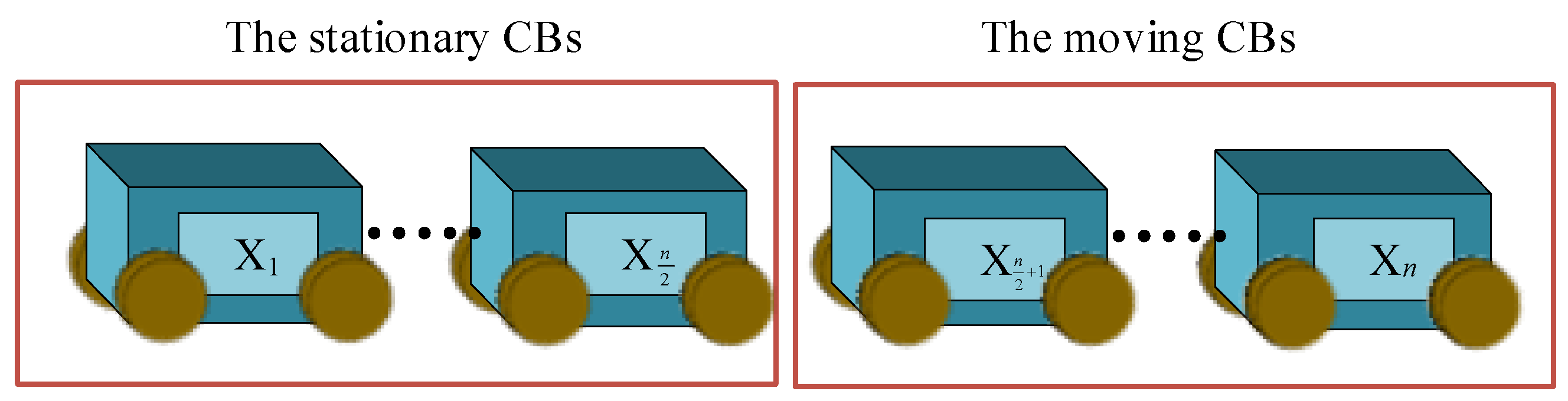
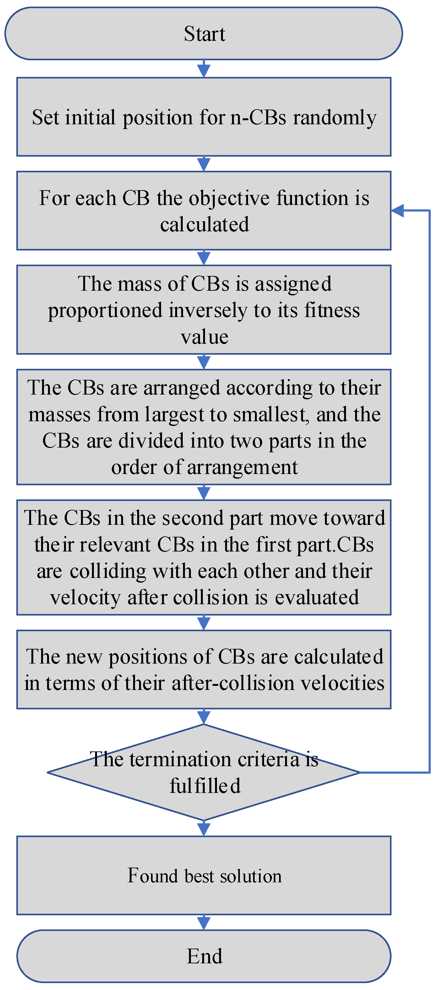
3.1. The Optimization Process of CBO

In the case of a one-dimensional collision of two objects in an independent system without external forces, the total momentum of the whole system is conserved, and the momentum of all objects before the collision is equal to the momentum of all objects after the collision, expressed by the following equation.
m 1 v 1 + m 2 v 2 = m 1 v 1 + m 2 v 2
1 2 m 1 v 1 2 + 1 2 m 2 v 2 2 = 1 2 m 1 v 1 2 + 1 2 m 2 v 2 2 + Q
where v 1 , v 2 indicates the initial velocity of the two objects before the collision, v 1 , v 2 indicates the final velocity of the two objects after the collision, and Q is the loss of kinetic energy [44] caused by the collision. Jointly (21) and (22) can be obtained after the collision velocity.
v 1 = ( m 1 ε m 2 ) v 1 + ( m 2 ε m 2 ) v 2 m 1 + m 2
v 2 = ( m 2 ε m 1 ) v 2 + ( m 1 + ε m 1 ) v 1 m 1 + m 2
ε = v 2 v 1 v 2 v 1 = v v
There are only two scenarios in any collision where ε is the coefficient of restitution (COR), defined as the ratio of relative separation velocity to relative approach velocity. One example is a collision that occurs when Q = 0 and ε = 1 is totally elastic. The difference between the relative velocities before and after a full impact is constant since there is no kinetic energy loss. The second scenario is when Q 0 happens, causing an inelastic collision and a partial loss of kinetic energy. As a result, the difference in velocities after the collision is smaller than the difference in velocities before the collision. To create a healthy balance between global search and local search throughout the optimization process, the COR is defined as the following equation [45]. The COR is used to govern the degree of global search and data mining by the algorithm.
ε = 1 i t e r i t e r max
The colliding bodies optimization (CBO) algorithm proposed by Kaveh and Mahdavi [46] is used to optimize the optimal parameters of the TMDI for different solid mass ratios and apparent mass ratios with frequency ratio (μ) and damping ratio (β) as functions of independent variables. CBO is a metaheuristic algorithm that does not require the adjustment of internal parameters and is suitable for the easy handling of complex black-box functions. The method has been successfully applied to the steady-state optimization of multi-degree-of-freedom structures of TMDI equipment [47]. The CBO pseudocode for the displacement minimization problem is as follows:
Within the preset boundary conditions, the positions of the colliding bodies are randomly generated, as shown in Equation (27).
x i = x min + r a n d ( x max x min ) , i = 1 , , n
where x i denotes the position of the i th colliding body after initialization, and x min represents the maximum and minimum values of the parameters to be optimized, respectively; rand( ) is a random number between [0,1], and n is the population size of the object.
For each CB, the objective function is calculated, as in Equation (28), where o b j i is the objective function.
o b j i = z ( x i ) , i = 1 , , n
The mass of CBs is assigned proportioned inversely to its fitness value.
f i t ( k ) = 1 obj i , i = 1 , , n m k = f i t ( k ) i = 1 n f i t ( k ) , k = 1 , , n
where computational convenience defines f i t ( k ) as the value of the fitness function of the i th collision body, which is inversely proportional to the objective function. It can be seen from Equation (29) that the smaller the fitness function the greater the quality of the individual, and the larger the fitness the smaller the quality of the function.
The population tie was divided into two parts according to the ascending order of fitness function values, as shown in Figure 6. The individuals with small fitness values in front of the ranking are divided into the stationary group, and the initial velocity of the stationary group before the collision is zero. The individuals with large fitness are divided into the collision group, and the initial velocity of the motion group before the collision is the difference between the relative positions of the colliding bodies.
Stationary   group : v i = 0 , i = 1 , 2 , , n 2 moving   group : v i = x i x i n / 2 , i = n 2 + 1 , , n
The CBs in the second part move toward their relevant CBs in the first part., and obtain the velocity of the stationary group after the collision and the velocity of the moving group after the collision, as shown in Figure 7.
Stationary   group : v i = ( m i + n / 2 + ε m i + n / 2 ) v i m i + m i + n / 2 , i = 1 , , n 2 moving   group : v i = ( m i ε m i n / 2 ) v i m i + m i n / 2 , i = n 2 + 1 , , n
The new positions of CBs are calculated in terms of their after-collision velocities.
Stationary   group : x i n e w = x i + r a n d v i , i = 1 , , n 2 moving   group : x i n e w = x i n / 2 + r a n d v i , i = n 2 + 1 , , n
where x i n e w , x i , and v i are the updated position, the position before the update, and the velocity after the collision occurred, respectively. rand( ) is a random number between [−1,1]. The symbol ‘∘’ implies a dot product.
If the current number of iterations is equal to the maximum number of iterations, the algorithm is terminated. Otherwise, Otherwise, re-execute the CBO. The flowchart of the CBO algorithm is shown in Figure 8.
The goal of this article is to minimize the maximum amplitude of the displacement response (called y 3 n ω ). From Equation (13), it can be seen that both the damping ratio and frequency ratio of the TMDI affect the displacement response of the transmission conductor. Therefore, by choosing reasonable optimization parameters, the displacement response can be effectively reduced. To control the maximum amplitude of the transmission conductor displacement response, a simple and efficient optimization procedure is used to generate the TMDI-optimized design parameters.
In this study, the number of CBs and the number of steps used in the optimization process are 20 and 30, respectively, and run 10 times, and finally, the average of the optimization results is taken. In the MATLAB vector representation, the range of preselected values is shown below:
μ = [ 0.01 : 0.01 : 0.32 ] , β = [ 0 : 0.02 : 1 ]
In this step, the displacement response is used as the objective function, and the frequency and damping ratio are used as design variables. In the MATLAB vector representation, the range of tuning values is shown below:
ζ 2 = [ 0 . 01 , 1 ] , γ = [ 0 , 1 ]

3.2. Numerical Analysis

To further verify the vibration response of the vertical displacement of the conductor under the action of the grounded TMDI, the effect of the grounded TMDI on the displacement response of the transmission conductor is analyzed. The transmission conductor is made of LGJ300/25 steel strand; its detailed parameters are shown in the following table. The conductor is hinged at both ends to simulate the suspension of the transmission conductor on the transmission tower and apply a tension of 20% breaking force, 83.41 × 20% = 16.68 kN.
The modal frequency of the nth order of the conductor, calculated [48,49] as:
ω 1 n = n π L T m 1 + n 2 π 2 E I L 2 T
Substituting Table 1’s parameters into Equation (35) yields the third-order modal frequency of the transmission conductor as: 38.421 rad/s. The excitation force with amplitude A(x) = 230 kN and frequency 38.421 rad/s will produce the third-order resonance of the transmission conductor. Due to the existence of real and imaginary parts, the formula for calculating the displacement amplitude is as follows.
Y = Y Re 2 + Y Im 2
As shown in Figure 9, the maximum displacement response at L/6, L/2, and 5/6 L of the conductor with the excitation force applied at 2.6 m from the end of the conductor is 0.3838. The vibration-damping effect of the TMDI at the maximum displacement of the conductor can be analyzed for all three conditions of the grounded TMDI installed at L/6, L/2, and 5/6 L from the conductor, so this paper unifies the analysis of the displacement response at L/2 of the conductor. The displacement response of the wire L/2 is analyzed, and the peak and trough positions (g = L/3) of the displacement response of the wire connected to both ends of the TMDI are used to analyze the vibration-damping effect of the TMDI.

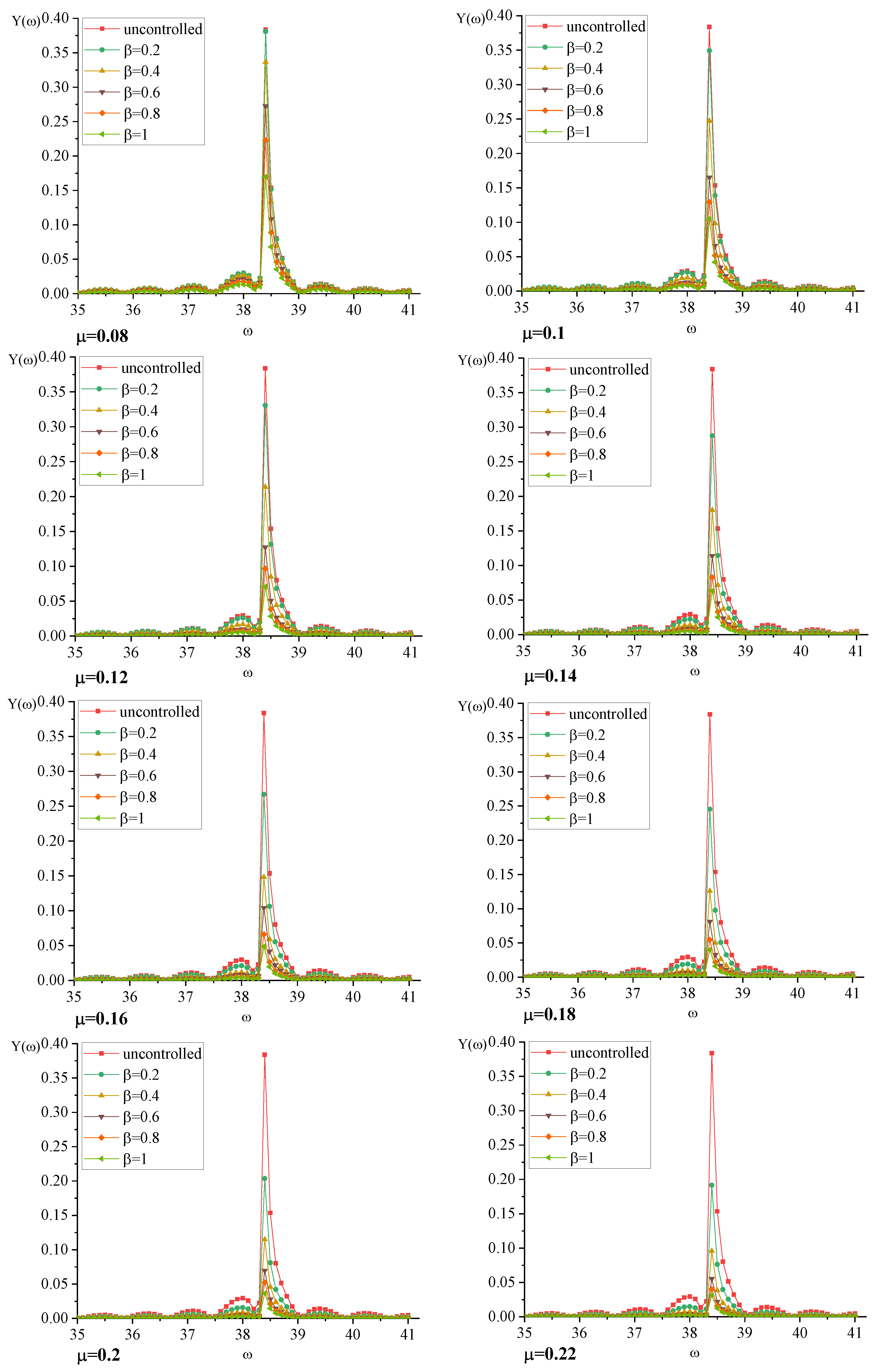
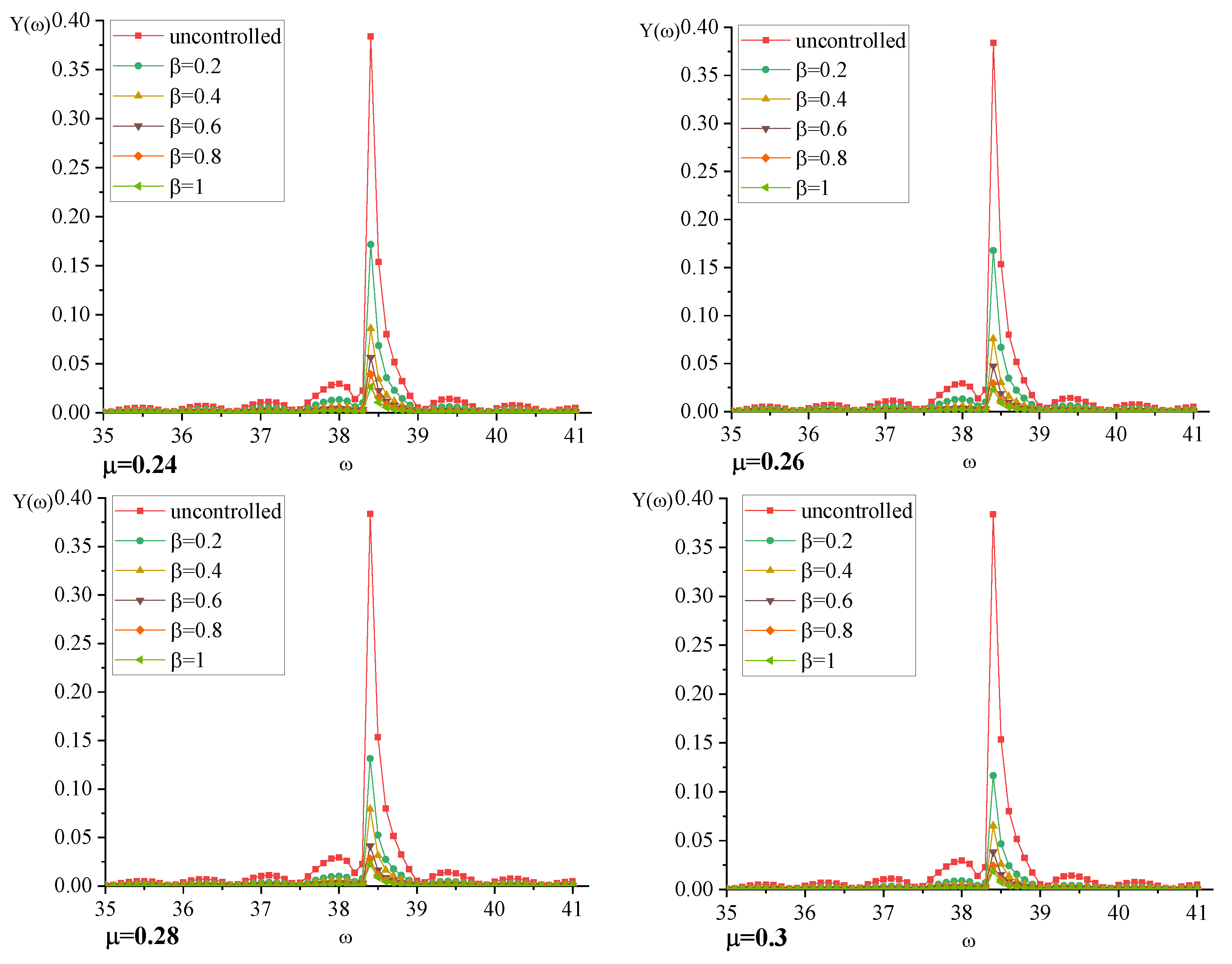
3.3. TMDI Validity Analysis

To study the effectiveness of the ungrounded TMDI on the control effect of transmission conductor breeze vibration response the mass ratio μ and apparent mass β of the ungrounded TMDI system are taken as [0.08, 0.02, 0.3] and [0.2, 0.2, 1], respectively. The optimal parameters of the ungrounded TMDI are obtained by the collision optimization algorithm, and the displacement response spectrum of transmission conductor-TMDI is obtained by substituting into Equation (14). The frequency domain response analysis of the transmission conductor under the excitation force is then carried out.
From Figure 10, the maximum displacement response of the conductor at the third-order modal frequency after installing the ungrounded TMDI decreases significantly in the frequency domain analysis, and the damping effect is better as β and μ increase. Compared with the displacement response of the uncontrolled transmission high line, the frequency domain analysis is performed in the working condition of β = 1 .
For μ = 0.08, 0.1, 0.12, 0.14, 0.16, 0.18, 0.2, 0.22, 0.24, 0.26, 0.28, and 0.3, there is a maximum displacement response at the third-order modal frequency ω 13 = 38.42. The peak maximum displacement response of the transmission conductor-TMDI is reduced by 56%, 68%, 72%, 81%, 83%, 87%, 89%, 90%, 91%, 93%, 94%, 94%, and 96%, respectively.
Equation (14), based on the ideal frequency ratio and damping ratio resolved by the CBO method, yields the displacement response of the conductor vibration. By varying the mass ratios μ and apparent mass ratio β , it is possible to examine the impact on the transmission conductor-grounded TMDI structure’s maximum displacement response, as well as the effects of the ideal frequency ratio γ o p t and damping ratio ζ o p t of the TMDI. The working conditions in Figure 11 are detailed in Equation (33), with a total of 1632 working conditions. It is important to note that the displacement responses corresponding to the x-axis (mass ratio μ ) and y-axis (apparent mass ratio β ) in the figure, which correspond to various frequency ratios γ o p t and damping ratios ζ o p t of the TMDI, should be taken into particular consideration. The displacement contour plot in the figure shows a noticeable color change from the bottom left to the upper right corner, which indicates that the displacement response is declining as μ and β rise. The control effectiveness reaches 96%, and the smallest displacement response is 0.016, J = 0.04. y ( ω ) crosses more contour areas as β rises when μ 0.15 , 0.3 , indicating that the TMDI has a stronger control impact.

4. Conclusions

In this study, the differential equations of motion of the transmission highline-TMDI under simple harmonic excitation are established, the displacement response of the transmission conductor acting on the TMDI is analyzed in the frequency domain based on the Fourier transform, and the response of the transmission highline-TMDI structure is optimized using a collision optimization algorithm based on a metaheuristic algorithm. The main findings are summarized in the following paragraphs.
(1) By putting forward reasonable assumptions and simplifying the structure of the tower-line system, the closed-form solutions of the control performance of the transmission conductor-TMDI (with arbitrary parameters μ, β, γ and ζ ) under the action of breeze are derived. The results show that the control performance using simple harmonic loads induced by breeze vibrations is mainly influenced by γ and ζ for structures dominated by fundamental modes, Equation (14).
To provide effective vibration damping, the nongrounded TMDI employs a connection form that creates the largest vibration differential between the two end connection points.
(2) Compared with the displacement response of the uncontrolled transmission high line, the frequency domain analysis is performed in the working condition of β = 1 .
μ = 0.08, 0.1, 0.12, 0.14, 0.16, 0.18, 0.2, 0.22, 0.24, 0.26, 0.28, and 0.3, and there is a maximum displacement response at the third-order modal frequency ω 13 = 38.42. The peak maximum displacement response of the transmission conductor-TMDI is reduced by 56%, 68%, 72%, 81%, 83%, 87%, 89%, 90%, 91%, 93%, 94%, 94%, and 96%, respectively. So it is more efficient to change μ when μ < 0.16 and more efficient to change β when μ > 0.16.
(3) For the controlled displacement response, as the mass ratio μ to the apparent mass ratio β of the transmission conductor-TMDI system increases and decreases, the damping capacity continues to improve, and the third-order modal vibration control efficiency can reach 96% without the constraints of engineering conditions.

Author Contributions

X.L. was mainly responsible for the grasp of the writing ideas of the article and put forward the innovative points of the article research. S.L. was in charge of the writing and first translation. C.W. and Y.B. were mainly responsible for literature queries and downloading. Y.Z. provide research funding and experiment-related material resources. All authors have read and agreed to the published version of the manuscript.

Funding

This research was funded by the National Natural Science Foundation of China (Grant No.52008070).

Institutional Review Board Statement

Not applicable.

Informed Consent Statement

Not applicable.

Data Availability Statement

Not applicable.

Conflicts of Interest

The authors declare that they have no known competing financial interests or personal relationships that could appear to influence the work reported in this paper.

References

  1. Deyi, K. Research of Transmission Line Aeolian Vibration Based on Dynamic Method. Ph.D. Thesis, Huazhong University of Science and Technology, Wuhan, China, 2009. [Google Scholar]
  2. Housner, G.W.; Bergman, L.A.; Caughey, T.K.; Chassiakos, A.G.; Claus, R.O.; Masri, S.F.; Skelton, R.E.; Soong, T.T.; Spencer, B.F.; Yao JT, P. Structural control: Past, present, and future. J. Eng. Mech. 1997, 123, 897–971. [Google Scholar] [CrossRef]
  3. Yao, J.T.P. Concept of structural control. J. Struct. Div. 1972, 98, 1567–1574. [Google Scholar] [CrossRef]
  4. Jinping, O. Structure Vibration Control; Science Press: Beijing, China, 2003. [Google Scholar]
  5. Crewe, A. Passive energy dissipation systems in structural engineering. Struct. Saf. 1998, 20, 197–198. [Google Scholar] [CrossRef]
  6. Feldmann, D. Aeolian vibrations: Possible effects of nonlinear behaviour of Stockbridge dampers. In Proceedings of the International Conference on Overhead Line Design & Construction: Theory & Practice, London, UK, 28–30 November 1988. [Google Scholar]
  7. Hou, J.; Wu, X.; Sun, Z. Research and progress of breeze vibration of anti-vibration hammer-transmission line system. J. Hefei Univ. Technol. (Nat. Sci. Ed.) 2011, 34, 743–747. [Google Scholar]
  8. Zhang, H. Examples of overhead transmission line breeze vibration hazards and the importance of field vibration measurement. Electr. Constr. 1997, 8, 4. [Google Scholar]
  9. Zhang, M.; Wu, T.; Øiseth, O. Vortex-induced vibration control of a flexible circular cylinder using a nonlinear energy sink. Wind. Eng. Ind. Aerodyn. 2022, 229, 105163. [Google Scholar] [CrossRef]
  10. Frahm, H. Device for Damping Vibrations of Bodies. U.S. Patent 9,899,58A, 18 April 1911. [Google Scholar]
  11. Huang, B.; Tang, J.X. Wind vibration control of self-supporting high-voltage transmission towers with large spans. Spec. Struct. 1997, 3, 49–52. [Google Scholar]
  12. Hu, S. Research on Wind Vibration Response and Vibration Control of Large-Span Transmission Lines. Ph.D. Thesis, Tongji University, Shanghai, China, 1999. [Google Scholar]
  13. Deng, H.; Zhu, S.; Chen, Y.; Wang, Z. Research on wind vibration control of large span transmission tower system. J. Build. Struct. 2003, 24, 60–64. [Google Scholar]
  14. Qu, C. Application of bidirectional TMD in the study of wind vibration control of transmission lines. Hydropower Energy Sci. 2012, 30, 195–199. [Google Scholar]
  15. Bisegna, P.; Caruso, G. Closed-form formulas for the optimal pole-based design of tuned mass dampers. J. Sound Vib. 2012, 331, 2291–2314. [Google Scholar] [CrossRef]
  16. Greco, R.; Marano, G.C. Optimum design of tuned mass dampers by displacement and energy perspectives. Soil Dyn. Earthq. Eng. 2013, 49, 243–253. [Google Scholar] [CrossRef]
  17. Zhang, M.; Xu, F. Tuned mass damper for self-excited vibration control: Optimization involving nonlinear aeroelastic effect. J. Wind. Eng. Ind. Aerodyn. 2022, 220, 104836. [Google Scholar] [CrossRef]
  18. Smith, M.C. Synthesis of mechanical networks: The inerter. IEEE Trans. Autom. Control 2002, 47, 1648–1662. [Google Scholar] [CrossRef] [Green Version]
  19. Ormondroyd, J.; Den Hartog, J.P. The theory of the dynamic vibration absorber. Trans. ASME 1928, 50, 9–22. [Google Scholar]
  20. Marian, L.; Giaralis, A. Optimal design of inverter devices combined with TMDs for vibration control of buildings exposed to stochastic seismic excitations. In Proceedings of the 11th International Conference on Structural Safety and Reliability, New York, NY, USA, 16–20 June 2013. [Google Scholar]
  21. Marian, L.; Giaralis, A. Optimal design of a novel tuned mass-damper–inerter (TMDI) passive vibration control configuration for stochastically support-excited structural systems. Probabilistic Eng. Mech. 2014, 38, 156–164. [Google Scholar] [CrossRef]
  22. Evangelou, S.; Limebeer DJ, N.; Sharp, R.S.; Smith, M.C. Steering compensation for high-performance motorcycles. In Proceedings of the 43rd IEEE Conference on Decision and Control, Atlantis, Paradise Island, Bahamas, 14–17 December 2004. [Google Scholar]
  23. Papageorgiou, C.; Smith, M.C. Laboratory experimental testing of inerters. In Proceedings of the 44th IEEE Conference on Decision and Control, and the European Control Conference, Seville, Spain, 12–15 December 2005. [Google Scholar]
  24. Long, C.; Hao, R.E.N.; Ruo-chen, W. Simulations and Tests for Mechanical Properties of a Hydraulic Inerter. J. Vib. Shock. 2014, 33, 87–92. [Google Scholar]
  25. De Domenico, D.; Ricciardi, G. Optimal design and seismic performance of tuned mass damper inerter (TMDI) for structures with nonlinear base isolation systems. Earthq. Eng. Struct. Dyn. 2018, 47, 2539–2560. [Google Scholar]
  26. De Domenico, D.; Ricciardi, G. An enhanced base isolation system equipped with optimal tuned mass damper inerter (TMDI). Earthq. Eng. Struct. Dyn. 2018, 47, 1169–1192. [Google Scholar] [CrossRef]
  27. Pietrosanti, D.; De Angelis, M.; Basili, M. Optimal design and performance evaluation of systems with Tuned Mass Damper Inerter (TMDI). Earthq. Eng. Struct. Dyn. 2017, 46, 1138–1367. [Google Scholar] [CrossRef]
  28. Giaralis, A.; Petrini, F. Wind-Induced Vibration Mitigation in Tall Buildings Using the Tuned Mass-Damper-Inerter. J. Struct. Eng. 2017, 143, 04017127. [Google Scholar] [CrossRef]
  29. Giaralis, A.; Petrini, F. Optimum design of the tuned mass-damper-inerter for serviceability limit state performance in wind-excited tall buildings. Procedia Eng. 2017, 199, 1773–1778. [Google Scholar] [CrossRef]
  30. Dai, J.; Xu, Z.D.; Gai, P.P. Tuned mass-damper-inerter control of wind-induced vibration of flexible structures based on inerter location. Eng. Struct. 2019, 199, 109585. [Google Scholar] [CrossRef]
  31. Zhang, Z.; Fitzgerald, B. Tuned mass-damper-inerter (TMDI) for suppressing edgewise vibrations of wind turbine blades. Eng. Struct. 2020, 221, 110928. [Google Scholar] [CrossRef]
  32. Lee, L.; Allen, D. Vibration frequency and lock-in bandwidth of tensioned, flexible cylinders experiencing vortex shedding. J. Fluids Struct. 2010, 26, 602–610. [Google Scholar] [CrossRef]
  33. Den Hartog, J.P. Mechanical Vibrations; Courier Corporation: North Chelmsford, MA, USA, 1985. [Google Scholar]
  34. Dong, F.; Sun, F.; Yin, W.; Chu, M.; Wang, B.; Chao, Z.; Yao, Z.; Gong, Q.; Jin, H. Two-stage design method for damping high-frequency TMD of steel plate sandwich. Adv. Build. Steel Struct. 2021, 23, 85–93+100. [Google Scholar]
  35. Li, Y.; Li, S.; Chen, Z. Optimization and performance evaluation of variable inertial mass-tuned mass dampers. J. Vib. Eng. 2020, 33, 21–28. [Google Scholar]
  36. Luo, H.; Zhang, R.; Shen, H.; Weng, D. Parameter optimization of tandem viscous mass dampers based on fixed-point theory. Struct. Eng. 2017, 33, 41–46. [Google Scholar]
  37. Ikago, K.; Saito, K.; Inoue, N. Seismic control of single-degree-of-freedom structure using tuned viscous mass damper. Earthq. Eng. Struct. Dyn. 2012, 41, 453–474. [Google Scholar]
  38. Barredo, E.; Blanco, A.; Colín, J.; Penagos, V.M.; Abúndez, A.; Vela, L.G.; Mayén, J. Closed-form solutions for the optimal design of inerter-based dynamic vibration absorbers. Int. J. Mech. Sci. 2018, 144, 41–53. [Google Scholar] [CrossRef]
  39. Hadi, M.N.; Arfiadi, Y. Optimum design of absorber for MDOF structures. Optimum design of absorber for MDOF structures. Univ. Wollongong 1998, 11, 124. [Google Scholar]
  40. Febbo, M.; Vera, S.A. Optimization of a two degree of freedom system acting as a dynamic vibration absorber. J. Vib. Acoust. 2008, 130, 011013. [Google Scholar] [CrossRef]
  41. Bozer, A.; Özsarıyıldız, S.S. Free parameter search of multiple tuned mass dampers by using artificial bee colony algorithm. Struct. Control Health Monit. 2018, 25, e2066. [Google Scholar] [CrossRef]
  42. Kaveh, A. Colliding bodies optimization. In Advances in Metaheuristic Algorithms for Optimal Design of Structures; Springer: Cham, Switzerland, 2014; pp. 195–232. [Google Scholar]
  43. Kong, D.; Li, L.; Long, X.; Liang, Z. Finite element analysis of breeze vibration of ultra-high voltage overhead transmission lines. Vib. Shock. 2007, 26, 4. [Google Scholar]
  44. Tolman, R.C. The Principles of Statistical Mechanics; Clarendon Press: Oxford, UK, 1979. [Google Scholar]
  45. Kaveh, A.; Fahimi Farzam, M.; Hojat Jalali, H.; Maroofiazar, R. Robust optimum design of a tuned mass damper inerter. Acta Mech. 2020, 231, 3871–3896. [Google Scholar] [CrossRef]
  46. Kaveh, A.; Mahdavi, V.R. Colliding bodies optimization: A novel meta-heuristic method. Comput. Struct. 2014, 139, 18–27. [Google Scholar] [CrossRef]
  47. Fahimi Farzam, M.; Kaveh, A. Optimum design of tuned mass dampers using colliding bodies optimization in frequency domain. Iran. J. Sci. Technol. Trans. Civ. Eng. 2020, 44, 787–802. [Google Scholar] [CrossRef]
  48. Jiancheng, M. Breeze Vibration of Large Span Transmission Lines. Master’s Thesis, Huazhong University of Technology, Wuhan, China, 1996. [Google Scholar]
  49. Zhang, Z.; Zhou, L.; Qi, Y.; Liu, S. Factors influencing the strength of breeze vibration of large span conductors. Vibration. Test. Diagn. 2021, 4, 710–714. [Google Scholar]
Figure 1. Schematic of Kármán vortex street.
Buildings 12 02200 g001
Figure 2. TMDI structure schematic.
Buildings 12 02200 g002
Figure 3. Three forms of the inerter: (a) rack–pinion inerter [22]; (b) ball–screw inerter [23]; (c) hydraulic inerter [24].
Buildings 12 02200 g003
Figure 4. Transmission wire-unground TMDI system model.
Buildings 12 02200 g004
Figure 5. Transmission line element diagram.
Buildings 12 02200 g005
Figure 6. Collision body sorting grouping.
Buildings 12 02200 g006
Figure 7. A pair of colliding bodies collide with each other.
Buildings 12 02200 g007
Figure 8. CBO pseudocode for the displacement minimization problem.
Buildings 12 02200 g008
Figure 9. Transmission wire displacement response with 3rd order mode.
Buildings 12 02200 g009
Figure 10. Displacement response of transmission conductors before and after installation of ungrounded TMDI under frequency domain analysis.
Buildings 12 02200 g010aBuildings 12 02200 g010b
Figure 11. Effect of damping ratio and apparent mass ratio on displacement response.
Buildings 12 02200 g011
Table 1. Transmission wire parameter table.
ParametersNumerical
Value
ParametersNumerical Value
Structure
Number
of
roots/diameter
(mm)
Aluminum48/2.85Outer diameter (mm)23.76
Steel7/2.22Calculation of pull-off force (N)83,410
Calculated areaAluminum306.21Modulus of elasticity (N/mm2)65,000
Steel27.1Mass per unit length (kg/km)1058
Total333.31Length of test section (m)30.84
Publisher’s Note: MDPI stays neutral with regard to jurisdictional claims in published maps and institutional affiliations.

