Article

Finite Element Modelling to Predict the Fire Performance of Bio-Inspired 3D-Printed Concrete Wall Panels Exposed to Realistic Fire

by
Thadshajini Suntharalingam
1,
Irindu Upasiri
2,
Brabha Nagaratnam
1,*,
Keerthan Poologanathan
1,
Perampalam Gatheeshgar
3,
Konstantinos Daniel Tsavdaridis
4 and
Dilini Nuwanthika
1
1
Department of Mechanical and Construction Engineering, Faculty of Engineering and Environment, Northumbria University, Newcastle upon Tyne NE1 8ST, UK
2
Department of Civil Engineering, Faculty of Engineering, University of Sri Jayewardenepura, Ratmalana 10390, Sri Lanka
3
School of Computing, Engineering, and Digital Technologies, Teesside University, Middlesbrough TS1 3BX, UK
4
Department of Civil Engineering, University of London, London EC1V 0HB, UK
*
Author to whom correspondence should be addressed.
Buildings 2022, 12(2), 111; https://doi.org/10.3390/buildings12020111
Submission received: 3 December 2021 / Revised: 13 January 2022 / Accepted: 19 January 2022 / Published: 24 January 2022
(This article belongs to the Section Building Structures)

Abstract

:
Large-scale additive manufacturing (AM), also known as 3D concrete printing, is becoming well-recognized and, therefore, has gained intensive research attention. However, this technology requires appropriate specifications and standard guidelines. Furthermore, the performance of printable concrete in elevated temperature circumstances has not yet been explored extensively. Hence, the authors believe that there is a demand for a set of standardized findings obtained with the support of experiments and numerical modelling of the fire performance of 3D-printed concrete structural elements. In general, fire experiments and simulations focus on ISO 834 standard fire. However, this may not simulate the real fire behaviour of 3D-printed concrete walls. With the aim of bridging this knowledge disparity, this article presents an analysis of the fire performance of 3D-printed concrete walls with biomimetic hollow cross sections exposed to realistic individual fire circumstances. The fire performance of the non-load-bearing 3D-printed concrete wall was identified by developing a suitable numerical heat transfer model. The legitimacy of the developed numerical model was proved by comparing the time–temperature changes with existing results derived from fire experiments on 3D-printed concrete walls. A parametric study of 96 numerical models was consequently performed and included different 3D-printed concrete wall configurations under four fire curves (standard, prolonged, rapid, and hydrocarbon fire). Moreover, 3D-printed concrete walls and mineral wool cavity infilled wall panels showed enhanced fire performance. Moreover, the cellular structures demonstrated superior insulation fire ratings compared to the other configurations.

1. Introduction

1.1. Three-Dimensional Concrete Printing (3DCP)

Additive Manufacturing (AM) technology in construction, generally known as Three-dimensional Concrete Printing (3DCP), has shown rapid development over the last decade, following a similar trend to such digital technologies as AI (Artificial Intelligence), BIM (Building Information Modelling), and VR (Virtual Reality) [1]. The word 3D Concrete Printing (3DCP) indicates various tools used to build 3D objects by stacking concrete layers until the required geometry is achieved [2,3].
Compared to conventional construction methods, 3DCP has shown technical, economic, social, and environmental benefits. This technique has offered room for creativity and design freedom for architects and engineers to develop intricate, customized structures that were previously neither possible nor achievable with the standard formwork and topological optimization approaches [4,5,6,7]. In addition, the unique advantages of 3DCP are higher potential construction quality, reduced construction time, the possibility of building innovative structures at lower associated costs, the development of material-minimized, resource-saving structures, the optimization of thermal and acoustic properties of buildings, and the reduction in arduous manpower and, hence, increased labour efficiency and safety. This process also reduces adverse environmental impacts by means of the direct use of natural materials, reduced transportation, reduced waste, and minimal energy usage [1,3,5,7,8,9,10,11,12,13,14,15].
When a novel technology is emerging, the basic constraints, including the desired mechanical behaviour, dimensional stability, fire resistance, and durability, must be studied comprehensively. Moreover, knowledge of the differences between large-scale 3DCP and laboratory 3DCP is still limited, with a lack of design rules and guidelines. In addition, it is also crucial to envisage its impact in terms of the environment, energy consumption, thermal efficiency, sustainability, and resilience for long-term accomplishment [7]. Hence, it is imperative that the built environment can achieve the required structural and thermal performance while reducing substantial energy consumption [16,17]. As a solution, the construction industry has embraced the use of bio-inspired designs that can provide improved energy performance with lessened adverse effects on the environment [5,18,19]. The integration of biomimicry in construction is evident in the use of cellular structures or lattice structures, which commonly offer improved stiffness and lightness properties with better thermal and acoustical characteristics [5].

1.2. Bio-Inspired Design for 3DCP

In nature, there are many biological structures that are complicated in shape but naturally optimized for different purposes, with excellent mechanical properties [20]. However, such nature-inspired design entities are complicated and are challenging to replicate with normal formwork concrete fabrications. Current advances in 3DCP have provided a pathway to build arbitrary and multi-material geometries with some highly exceptional design strategies witnessed in nature, encouraging a surge in the research of biomimetic design [21]. Lately, a growing number of studies on the construction and assessment of bio-inspired structures have been performed owing to the development of 3DCP [12,22]. Plessis et al. [23] comprehensively reviewed the potential for the integration of bio-inspired design for 3D concrete printing. The study claims that extrusion-based 3DCP works perfectly to produce simple cellular structures. Wang et al. [24] 3D printed some wall panels with bio-inspired hollow sections, such as lattice, triangular, truss, and cellular areas, and tested their mechanical behaviour (Figure 1). Panda et al. [25] experimentally analysed the mechanical properties, such as the yield strength and elastic modulus, of hexagonal honeycomb cellular structures that were 3D printed using the Fused Deposition Method (FDM).
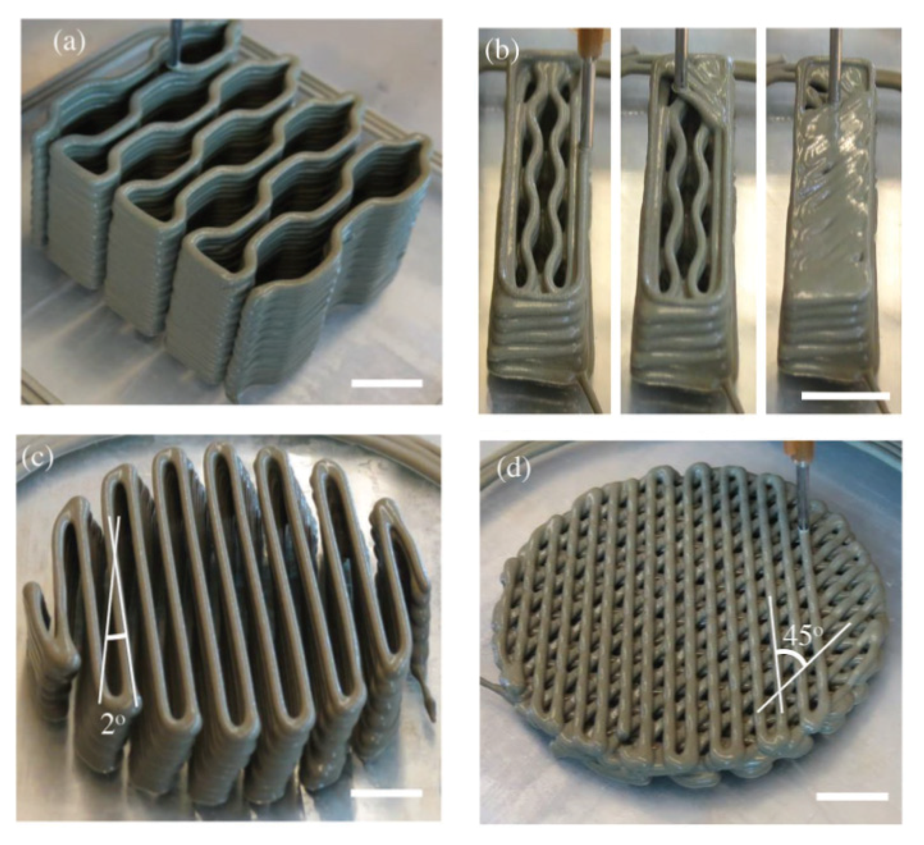
Moini et al. [26] 3D printed some bio-inspired designs, such as honeycomb, cellular panel, and Bouligand shapes, using cementitious material and found that these sections had improved crack resistance and toughness, and that inelastic deflection and failure were reduced by over 50% compared to the conventional manufactured elements [26] (Figure 2).

1.3. Fire Performance of Construction Materials

Many concepts and design methods have been established in order to identify the structural performance of 3D-printed concrete wall panels at ambient temperature. However, the fire behaviour and thermal performance of these structures under elevated temperature have not been sufficiently investigated to bridge the knowledge gap with real life practice.
The fire resistance and thermal performance of normal weight, light-weight concrete and steel have been analysed significantly, with well-established design guidelines developed for elevated temperatures [27,28,29,30,31,32,33,34]. These studies include the following: a comparative study of the fire behaviour of light-weight and normal concrete composite structures [31]; large-scale experiments conducted to examine the behaviour of concrete elements under standard fire conditions [33]; a study of the effect of raised temperature on concrete bond strength [27]; a numerical analysis of the fire performance of Composite Sandwich Panels (CSP) under standard fire and hydrocarbon fire conditions [28]; an examination of the effect of hydrocarbon fire on high-strength geopolymer concrete wall panels [29]; and a thermal analysis of multi-layer walls [34].
In terms of steel material, Steau et al. [35] presented the thermal properties of carbon steels, which are generally used in cold-formed LSF (light-gauge steel) frame systems. In addition, Gunalan and Mahendran [36] predicted the fire-resistance levels (FRL) of cold-formed steel wall panels to LSF standard fire. Steau et al. [37] experimentally studied fire-resistant board structures that were exposed to standard fire in order to increase the FRL. Gunalan et al. [38] experimentally studied the fire performance of load-bearing cold-formed steel wall panels under standard fire conditions, and Ariyanayagam and Mahendran [39] studied the same phenomena under realistic-design fire conditions and established fire design rules [40]. Ariyanayagam and Mahendran [41] also investigated the impact of cavity insulation on the fire resistance of LSF walls and found that the use of cavity insulation enhanced the FRL of non-load-bearing walls, although it considerably reduced that of load-bearing walls. In addition, experimental analyses of non-load-bearing LSF walls in standard fire conditions [42,43,44] and a large variety of fire performance data for LSF walls, obtained using finite element analysis (FEA) [45,46,47,48,49], are available for steel structures.
Though the standard fire curve has been used for centuries to determine the FRL of building elements, the actual FRL of building components subjected to real fires are considerably less than those obtained from standard fire tests [40,47]. Hence, the ISO 834 standard fire test regulations are not suitable for evaluating the fire performance of 3D-printed concrete walls in terms of establishing the highest temperature and the corresponding time taken to reach this highest temperature level [50].

1.4. Performance of 3DCP Structures under Elevated Temperature

The elevated-temperature thermo-mechanical behaviour of 3D-printed concrete is anticipated to be distinct from that of normal concrete at elevated temperatures due to its special mix design, its fabrication process, and the uneven distribution of its pore structure [30,51,52]. However, very little research has focused on assessing the fire performance of 3DCP. Hence, it is vital to understand the effects of this new layer-based construction technique on the fire performance of 3D-printed concrete elements.
Cicione et al. [53] pioneered the experimental evaluation of the fire behaviour of 3DCP. The authors heated six samples of 3D-printed concrete and three samples of mould casted using radiant panels, and identified that the 3D-printed concrete samples experienced thermal–mechanical spalling in the form of the interlayer delamination. Furthermore, Cicione et al. [54] investigated, through experiments, the impact of transverse confinement and longitudinal confinement (boundary conditions) on the inter layer bond of 3D-printed concrete elements at elevated temperatures. Weng et al. [52] conducted experimental research to investigate the printability and fire performance of 3D-printed fibre-reinforced cementitious composites under elevated temperatures. In addition, Pessoa et al. [5] conducted a systematic review of the thermal performance and thermal efficiency of 3D-printed concrete buildings. Yazyev et al. [11] proposed a thermal engineering calculation to determine the thermal properties and surface quality of 3D-printed concrete wall panels with a total width of 150 mm and an internal air layer with 75 mm thickness. In addition, Xiao et al. [51] experimentally investigated the mechanical and microstructural development of 3D-printed concrete under extremely high-temperature environments. The main findings from the study were that the 3D-printed concrete experienced layer delamination instead of spalling failure at elevated temperatures, and that temperature-related impacts on the microstructure of 3D-printed concrete were notable at temperatures over 400 °C.
Sun et al. [55] performed an on-site full-scale thermographic inspection and heat transfer monitoring experiment to investigate the thermal performance of a real 3D-printed concrete prototype building. The results revealed extremely non-uniform temperature dispersal on the outer wall surface of the examined house, as well as inadequate thermal insulating performance. Moreover, Kaszynka et al. [56] determined the thermal properties of a 3D-printed concrete wall that was constructed using High Performance Concrete (HPC) and insulated with mineral wool, and it was found to achieve the thermal and humidity conditions of traditional types of walls such as insulated brick, concrete, and stud walls. The study found that the lower thickness (8 cm) 3D-printed concrete wall reached the same thermal standards as traditional masonry or concrete walls (14 cm) with mineral wool insulation. Hence, further research is required to investigate the thermal properties of 3D-printed concrete elements, and research into additional insulation systems is also necessary.
Furet et al. [1] proposed a new advanced technology, Batiprint3DTM, for producing a 3D-printed intricate wall panel arrangement of a printed concrete wall encased with two polyurethane foam-printed outer walls to offer both internal insulation and external insulation to the structure without necessitating thermal bridges. Thus, the construction cost could be reduced by around 20% compared to that of masonry blocks with insulation [1]. Kaszynka et al. [56] constructed a wall panel with 5 cm mineral wool and 14 cm polyurethane foam sandwiched between the 3 cm 3D-printed concrete layers. Yang et al. [57] proposed a novel hybrid heat-storage system to overcome the insulation restrictions encountered in nonlinear 3D-printed concrete structures.
In addition, Alchaar and Al-Tamimi [58] studied the compressive, flexural, and interlayer bond strength variation of 3D-printed concrete with increasing ambient temperature. The results revealed that hot weather accelerated the water evaporation, which led to surface dryness and instigated reductions in the interlayer bond and compressive strength, whereas the flexural strength was increased by 18% at elevated temperatures, which were associated with the ambient-temperature samples due to their lesser material viscosities and better fibre orientation.
It is also vital to study the enduring sustainability of structures manufactured using the 3DCP technique. It is of particular importance to study the environmental sustainability aspects that specifically relate to thermal comfort, acoustic performance, and structural energy efficiency, which influence the indoor environment quality. Marais et al. [59] performed a computational evaluation of 3D-printed concrete wall structures with cavities for thermal performance and presented related thermal improvement strategies. In addition, the results showed that the solid light-weight foam concrete wall had better thermal performance compared to 3D-printed light-weight foam concrete walls with large wide cavities. However, the reduction in cavity widths led to enhanced thermal insulation. Mahadevan [60] conducted a study to examine the energy efficiency and thermal comfort of a building constructed using 3D-printable concrete, M25-strength concrete, and brick masonry, and claimed that the thermal performance of the 3D-printed concrete structure is not persuasively appropriate in the long term compared to other materials. This encourages the need for further in-depth research into 3D-printed concrete structures with environmental sustainability.
However, the performance of innovative biomimetic 3DCP structures in terms of fire resistance and thermal properties is, to date, very limited. In addition, the majority of research on 3D-printed concrete has, so far, been experimental, with not much attention given to computational simulations. Furthermore, the fire performance of 3D-printed concrete walls varies based on numerous factors such as the printable material’s composition, material density, wall thickness, wall cross-sectional arrangements, and type of insulation. Therefore, researchers previously investigated some 3D-printed concrete non-load-bearing wall panels with different cross-sectional configurations, such as triangular, lattice, and sinusoid, with a focus on investigating fire resistance and thermal behaviour under standard fire conditions and different real fire circumstances. (i.e., hydrocarbon fire, rapid fire, and prolonged fire) [16,17,30,50].

1.5. Scope of the Study

This research aimed to broaden the recent numerical analysis of the fire performance of 3D-printed concrete non-load-bearing wall panels. Thus, bio-inspired hollow cross sections, under realistic fire curves, were incorporated in this study. In line with the currently available geometries of 3D-printed concrete walls in the construction industry and the cavity provisions proposed by Wang et al. [24], this study numerically examined the fire behaviour of advanced wall configurations. The heat transfer numerical model, developed using Abaqus finite element software [61], was verified using the experimental outcomes provided by Cicione et al. [30,53]. The precision of the developed computational framework was validated by comparing the time–temperature variation with existing fire test results. Additionally, parametric modelling was performed to obtain a thorough understanding of the effects of different cross sections, with 96 numerical models, under four real fire situations including standard fire, hydrocarbon fire, rapid fire, and prolonged fire, with a concrete density of 2400 kg/m3. Following the introduction, methodologies for developing the FE model and validating the developed model based on existing experimental results are described in Section 2. Then, the numerical outcomes of the fire performance of 3D-printed wall panels are discussed and compared. Finally, the main findings of this research are stated in the last section.

2. Finite Element Model Development

This section describes the development of FE heat transfer model of 3D-printed concrete walls. Six different wall configurations, a cavity, and a cavity filled with mineral wool insulation material were studied via FE analysis. Marais et al. [59] identified that when the temperature is consistent along the exterior surface of the 3D-printed wall panel, the three-dimensional (3D) problem can be simplified to a two-dimensional (2D) problem, with suitable thermal properties and boundary conditions assigned. Hence, 2D heat transfer analysis was conducted to evaluate the insulation fire performance of the 3D-printed walls using the ABAQUS FEM package [61]. Four types of fire conditions, standard fire, hydrocarbon fire, rapid-fire, and prolonged fire, were applied to the 3D-printed wall configurations. The temperature variation of the unexposed surface was evaluated. Based on the unexposed surface temperature increment, the insulation fire rating was determined.

2.1. Thermal Properties of 3D-Printed Concrete at Elevated Temperature

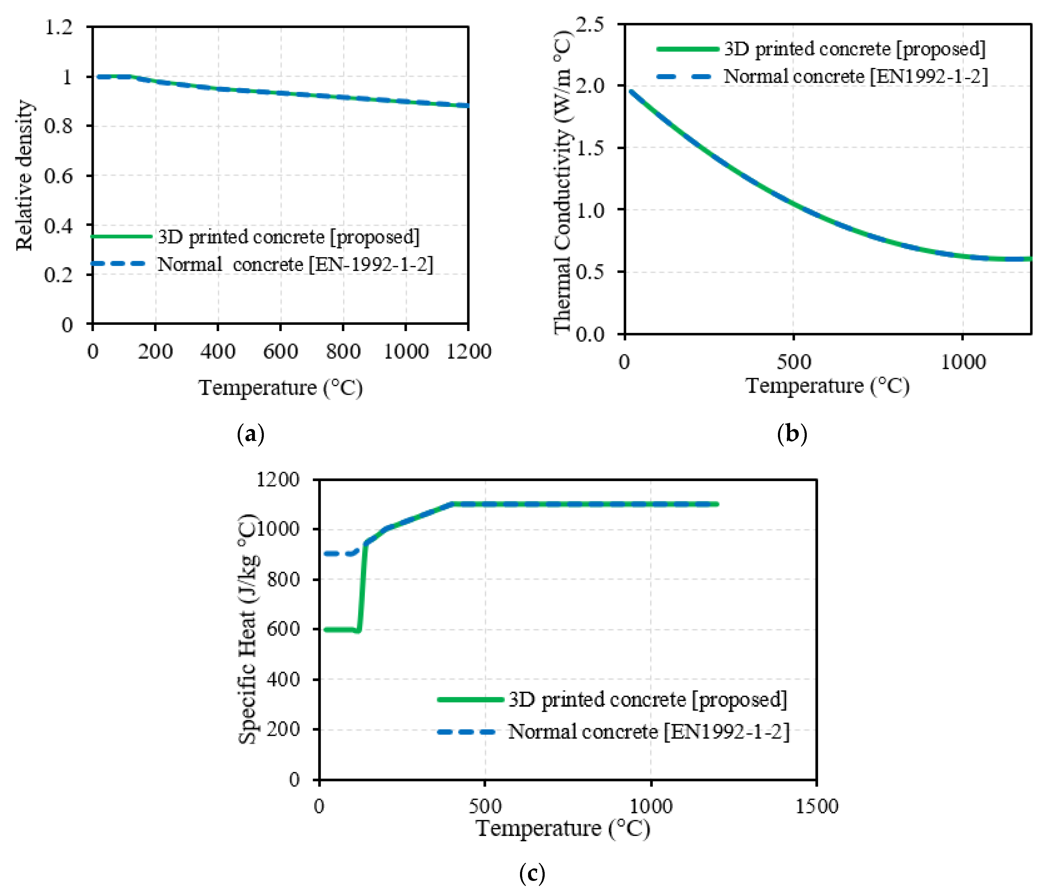
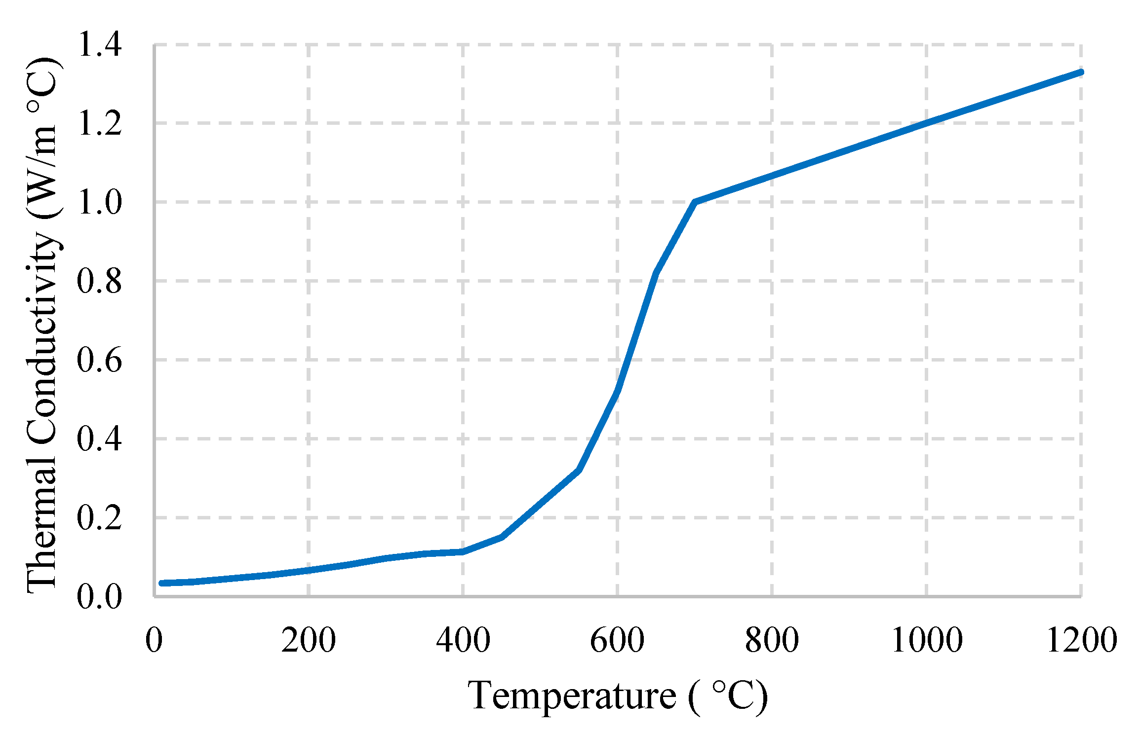
It is important to incorporate material properties at elevated temperatures into the model since material properties change with temperature, and at each time step, the temperature distribution varies with the fire exposure. Moreover, the fire design of 3D-printed concrete requires proper knowledge of thermal properties at elevated temperatures as the printable concrete mix behaves differently from conventional aggregate concrete. In order to numerically model the thermal behaviour of the structure to precisely predict the FRL, accurate estimation of thermal properties is essential. Hence, the thermal conductivity, specific heat, and relative density of the 3D-printed concrete with elevated temperature are required. In this study, these temperature-dependent thermal properties, obtained from EN 1992-1-2 [62], were used with suitable modification for heat variation within the 20–120 °C temperature range, whilst thermal conductivity and relative density changes followed the conventional concrete behaviour [30]. These revisions were validated against the results of experimental fire test of 3D-printed concrete (described in Section 3). Figure 3 illustrates the considered and proposed thermal properties of 3D-printed concrete at higher temperatures. As this analysis covers the impact of cavity insulation on the fire performance of a 3D-printed concrete non-load-bearing wall, the thermal properties of the mineral wool material are also explained in this section (Figure 4). For the mineral wool material, the constant density of 80 kg/m3 and the specific heat of 840 J/kg °C are considered at elevated temperatures [49].

2.2. Heat Transfer FE Model

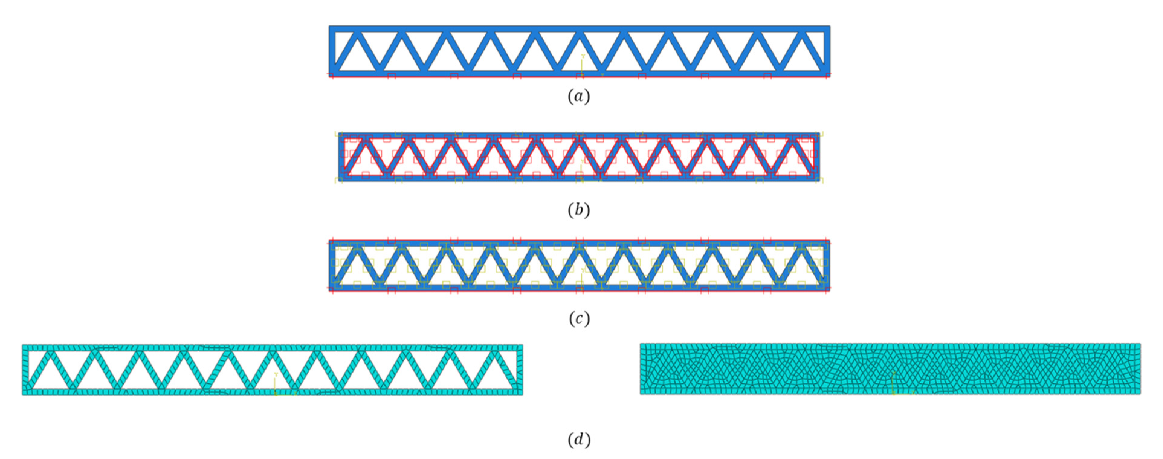
The following steps were conducted in order to model and analyse the 3D-printed concrete walls under fire-exposure conditions. Initially, the geometry of the model was created. The wall configuration was considered alongside the cavity, and the same wall configuration was considered when the cavity was filled with mineral wool insulations. Therefore, wall geometries created with the void (cavity) and cavity filling parts were produced separately and assembled when the walls, which were filled with insulations, were modelled, as shown in Figure 5. Once the geometry was created, material properties were assigned to the geometry.
A heat-transfer time step, with a time period of 14,400 s (4 h), was created to evaluate the insulation fire rating of the walls. Fire exposure was assigned as a temperature boundary condition. Due to convection and radiation, heat loss was incorporated with the emissivity value of 0.7 and the convection coefficient of 25 W/m2 °C [30], which were assigned as interaction properties for the exposed and unexposed wall surfaces. For walls containing a cavity, heat transfer through the cavity was modelled considering the heat transfer through radiation. Many studies have concluded that heat transfer in voids is governed by heat transfer through radiation [28,46,63]; therefore, the emissivity value of 0.7 was assigned to the cavity surfaces, and was modelled based on closed cavities in the geometry [62]. For walls filled with insulation material, tie constraints were assigned between the wall and the filling material to model the perfect connection between the two surfaces in the heat transfer process. Figure 6 illustrates the Abaqus modelling snapshots of the above-mentioned modelling steps.
Analysis was conducted for the prescribed time period, and the temperature distribution of the wall over time was generated. The temperature variation of the unexposed surface of the wall was considered for the determination of the insulation fire rating, as described.

2.3. Elevated Temperature Properties Variation in a Real Fire

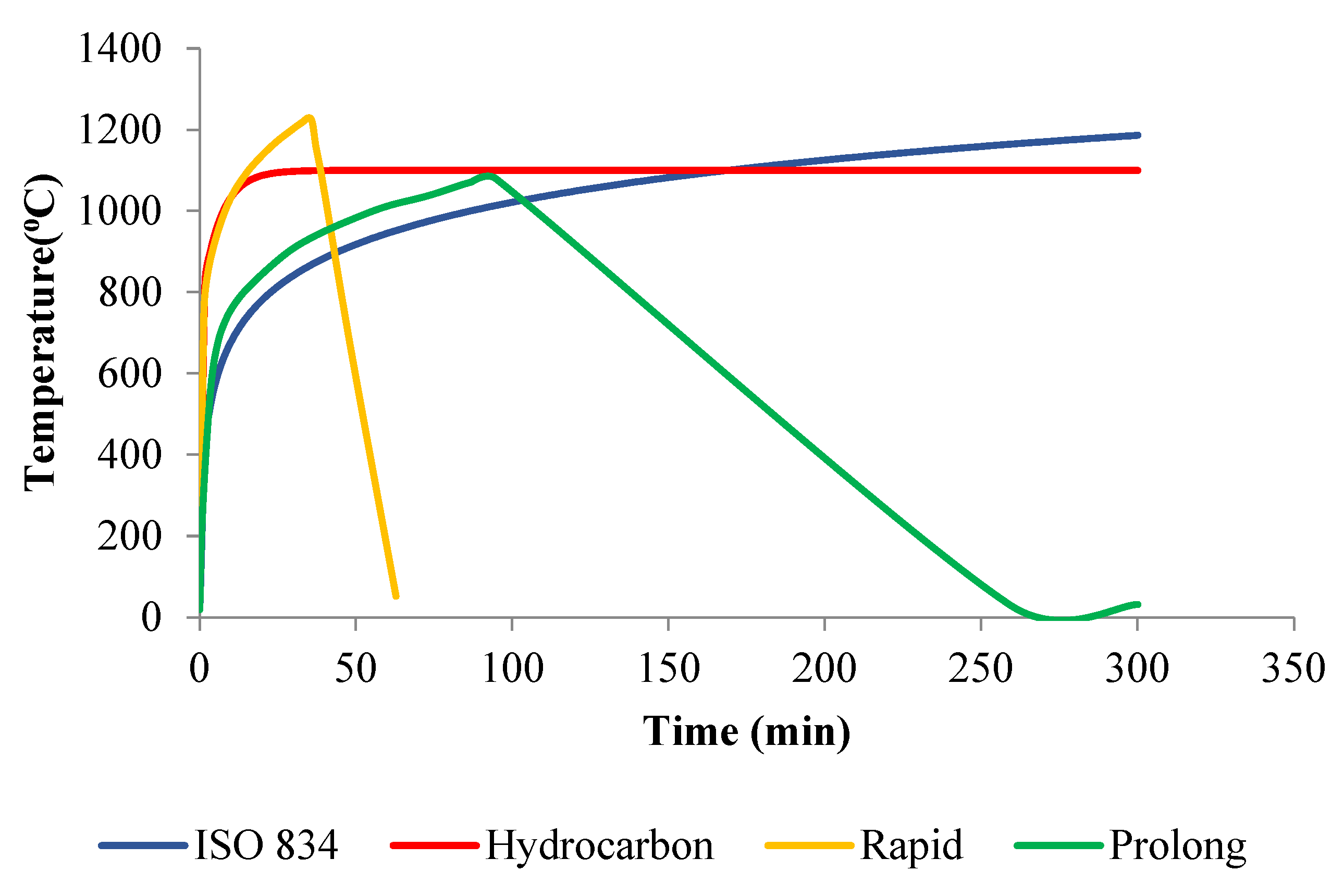
Fire exposure can be represented as the temperature variation of the flame over time. This temperature variation over time can be assigned as a boundary condition in fire testing as well as numerical analysis. Fire temperature varies with the fuel load, ventilation characteristics, compartment usage, and openings of the compartment [64,65,66,67,68,69]. Different standards have defined different time–temperature variations (fire curves), representing fire being induced under different conditions [68]. ISO834 and ASTM E119 are two commonly used fire curve standards. Fire curve standards are used to compare the fire behaviour of structural elements. However, standard fire does not simulate the actual fire situation. The hydrocarbon fire curve is another commonly used fire curve that represents the inducing of fire under high fuel loads in fuel sheds and industrial facilities. Due to the availability of high fuel loads, hydrocarbon fire is more severe than standard fire. Moreover, parametric fire curves were developed to represent more realistic temperature variations of fire in specific conditions [49,68,69]. Eurocode has specified parametric fire curves based on the fuel load, boundary materials, and compartment’s opening size. Two parametric fire curves were considered in this study based on the parameters specified in Table 1. Parametric fire contains both heating and decay phases, whereas standard fire and hydrocarbon fire encompass only the heating phase. Once the burning fuel is burnt off in the actual fire, the fire temperature lowers, resulting in a decay phase. This realistic situation is represented in parametric fire curves. Even in this study’s Eurocode parametric fire curves, both the heating and decay phases can be seen (Figure 7).
The developed FE model considers fire exposure as a time–temperature variation boundary condition, and the material properties at elevated temperature are incorporated into the model to achieve accurate results. These thermal properties were assigned to the model as temperature-dependent properties, as shown in Figure 8. However, when parametric fires are considered, these properties are valid only for the heating phase. During the rapid-fire exposure, the wall undergoes a temperature variation of ambient to 1200 °C in the heating phase and a 1200 °C to 52 °C temperature reduction in the decay phase. Therefore, if only temperature-dependent properties are accommodated, 3D-printed concrete wall density would decrease from 2400 kg/m3 to 2200 kg/m3 in the heating phase. Again, density would be increased to 2400 kg/m3 in the decay phase. However, it is evident that during the fire exposure, a mass gain cannot happen in the wall. Therefore, the thermal properties must be dependent on the temperature and the fire phase (heating or decay) to more realistically simulate the fire behaviour of walls during parametric fire exposure.
Temperature and phase-dependent thermal properties were incorporated in the FE modelling using the USDFLD subroutine. Thermal conductivity, specific heat, and each material’s density were assigned as field-dependent properties in the ABAQUS interface. Fortran code was developed to check the temperature and the phase of the fire for each element in each time step and, based on both conditions, the appropriate properties were selected. For instance, during the rapid-fire exposure, it was found that the 3D-printed concrete density would change from 2400 kg/m3 to 2200 kg/m3 in the heating phase, and that it would remain at 2200 kg/m3 in the decay phase. This ABAQUS model, with the USDFLD subroutine, was considered for all the wall configurations to analyse their behaviour in parametric fire conditions.

3. Validation

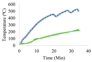
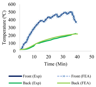
Validation of a numerical FE model is a process of authentication of the exactitude of the models in terms of presumed revisions and the material characterization associated with the existing experimental results. For the validation procedure, the study by Cicione et al. [53] was used, in which the performance of 3D-printed concrete at elevated temperatures was investigated experimentally. The fire test results from this study, which were obtained for three 3D-printed concrete (3DPC) panels of 160 × 165 × 50 mm and three 3D printed and cut samples (C3DPC) of 160 × 160 × 40 mm, were used for this FE model validation.
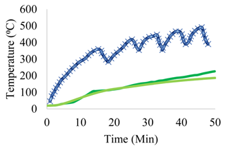
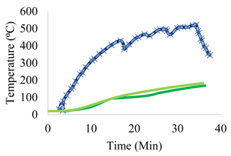
The detailed validation was previously conducted by the authors for heat transfer FE models in 2D and 3D using ABAQUS [61], and also for 2D heat transfer FE models using MATLAB. The created FE models were verified against the findings acquired from the existing experimental study [30]. The unexposed surface temperatures of the experimental curves and the FEA curves showed excellent agreement. Since the time–temperature variation results were nearly identical, it could be assumed that the revised thermal properties identified for the 3D-printed concrete could be applied for the parametric study of the fire performance of 3D-printed concrete walls. Since this study focused on 2D analysis, the evaluation of experimental results with 2D FEA in ABAQUS is presented in Table 2 for 3DPC samples and C3DPC samples, respectively.

4. Parametric Study of 3D-Printed Concrete Wall Section Specimens

This section covers the parametric study conducted to obtain the insulation fire ratings of non-load-bearing 3D-printed concrete wall panels with biomimetic hollow cross sections under realistic fire curves using the validated FE model. The time needed for the unexposed surface to become 160 °C was quantified as the insulation fire rating of these wall panels. From a previous study undertaken by the authors [30], it was found that the insulation fire rating was increasing with the increasing of the density regardless of the wall thickness. Hence, the printable concrete with a density of 2400 kg/m3 was selected in this study for further analysis. Six (6) 3D-printed concrete wall panels with biomimetic hollow cross sections (C1, C2, C3, C4, C5, and C6) were involved in this study, and those wall panels were then combined with the Mineral wool cavity insulation to enhance the fire behaviour (CI1, CI2, CI3, CI4, CI5, and CI6). Consequently, the model was expanded to study 96 3D-printed wall specimens against several parameters, such as wall thickness (100 mm and 200 mm), and six different wall structures with and without cavity insulation. In this study, heat transfer analysis was performed on wall panels with thicknesses of 100 mm (12 mm layer thickness) and walls with thicknesses of 200 mm (25 mm layer thickness). The nozzle sizes were chosen based on the real constructed structures. The different wall panels with biomimetic hollow cross sections are shown in Table 3 and the same wall panels were examined with mineral wool cavity insulation. The detailed parametric study outline is presented in Table 4.

5. Results and Discussion

5.1. Standard Fire

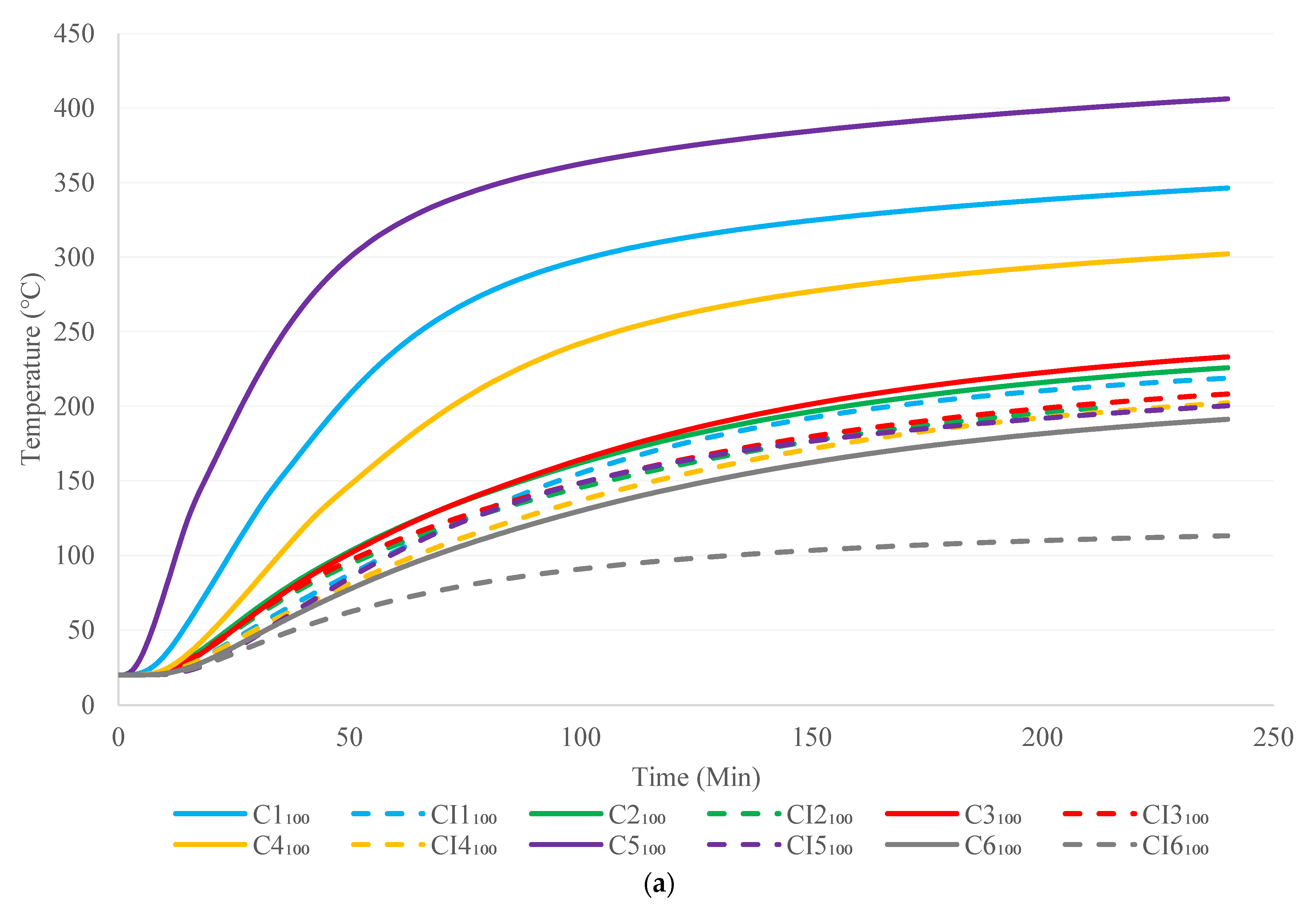
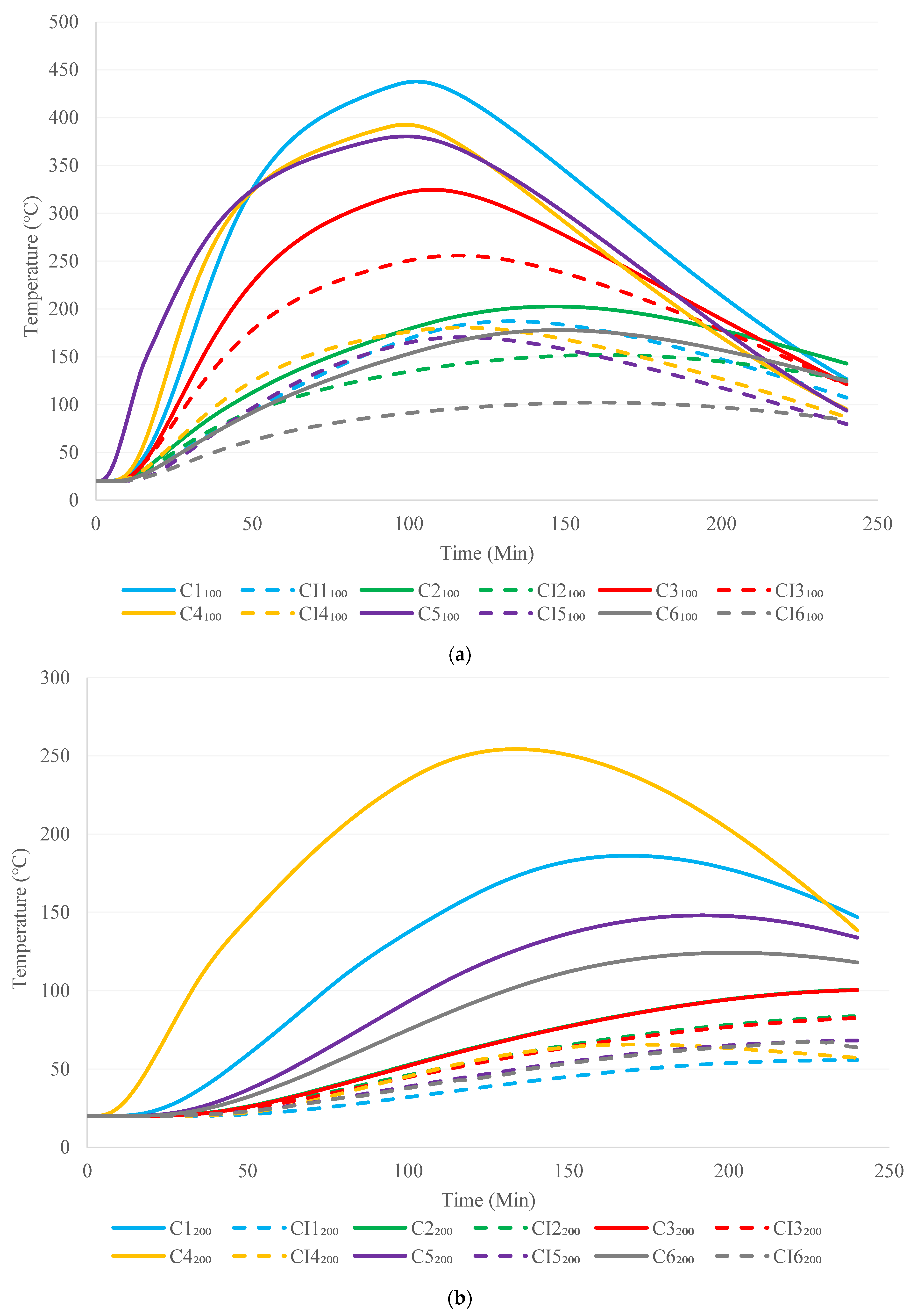
Figure 9a,b illustrate the unexposed surface temperature–time history of different 3D-printed concrete walls, of 100 mm and 200 mm thickness, respectively, subjected to standard fire. The temperature increment in the unexposed surface of the 100 mm wall panels was considerably higher at the early time-point, whereas gentler temperature increased were observed at the latter stage. However, the 200 mm thickness wall panels showed relatively lower temperature increases at the beginning, as compared to the 100 mm walls, and hence, showed better fire performance with a higher insulation fire rating in most of the cases. Therefore, it could be concluded that the increase in wall thickness resulted in enhanced fire performance. In terms of the different cross-sectional configurations, the C6 cellular cross-sectional wall panel exhibited superior fire performance compared to other wall panels with and without mineral wool insulation. Moreover, the C2 and C3 double-row wall panels with triangular sections showed enhanced fire performance compared to the single-row wall panels with truss and lattice sections, namely C1 and C5, for both the 100 mm and 200 mm wall panels. The introduction of higher intermediate barriers could be the reason for the reductions in material conductivity; hence, an improved insulation fire rating was obtained. In contrast, the C4 wall configuration with a double-row lattice arrangement showed somewhat similar behaviour regardless of the wall thickness. Moreover, it is obvious that the use of the mineral wool-infilled cavity walls resulted in improved fire performance with lower temperature at the unexposed surface as compared to that of cavity walls, irrespective of the cross-sectional arrangements and wall thicknesses. The C6 cellular cross-sectional wall panel showed the highest performance under fire among the 100 mm walls, and the CI1 truss cross-sectional wall exhibited the highest performance under fire among the 200 mm walls with mineral wool cavity insulation.

5.2. Hydrocarbon Fire

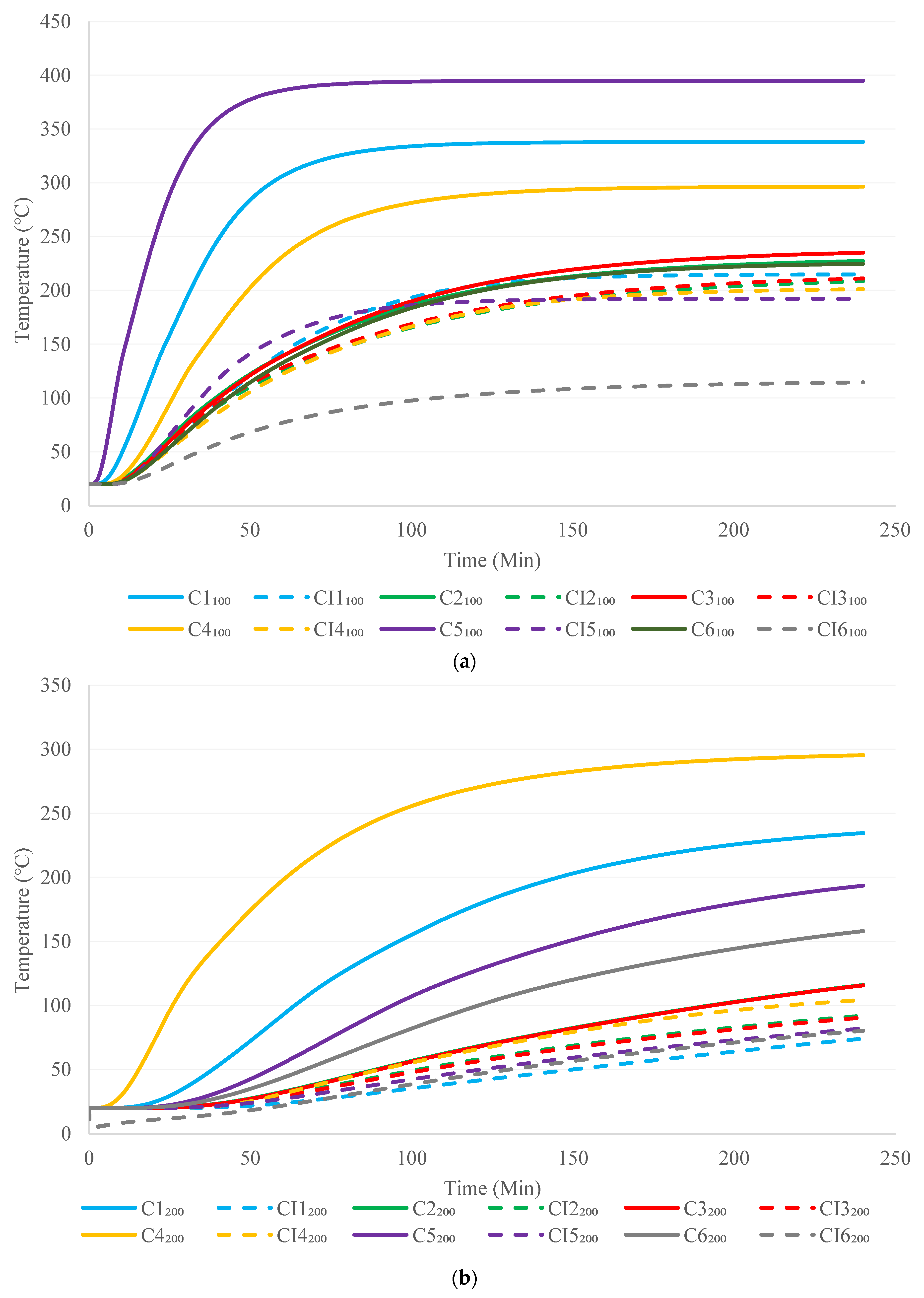
The time–temperature changes of the unexposed side of the 3D-printed concrete wall panels, with 100 mm and 200 mm wall thickness, under hydrocarbon fire conditions, are presented in Figure 10a,b. Similarly to the results obtained under standard fire conditions, a higher temperature increase was observed for the unexposed surface at the early stage for the 100 mm wall panels, and a comparatively lesser increment was noted for the 200 mm walls. The hydrocarbon fire scenario resulted in nearly identical behaviours of the time–temperature profiles of standard fire for all of the different cross sections. The CI6 cellular cross-sectional wall panel presented the highest performance among the 100 mm walls and the CI1 truss cross-sectional wall exhibited the highest performance under fire among the 200 mm walls with mineral wool cavity insulation. Moreover, the unexposed surface temperature reached a persistent value over time at later phases due to the nature of the hydrocarbon fire response.

5.3. Rapid Fire

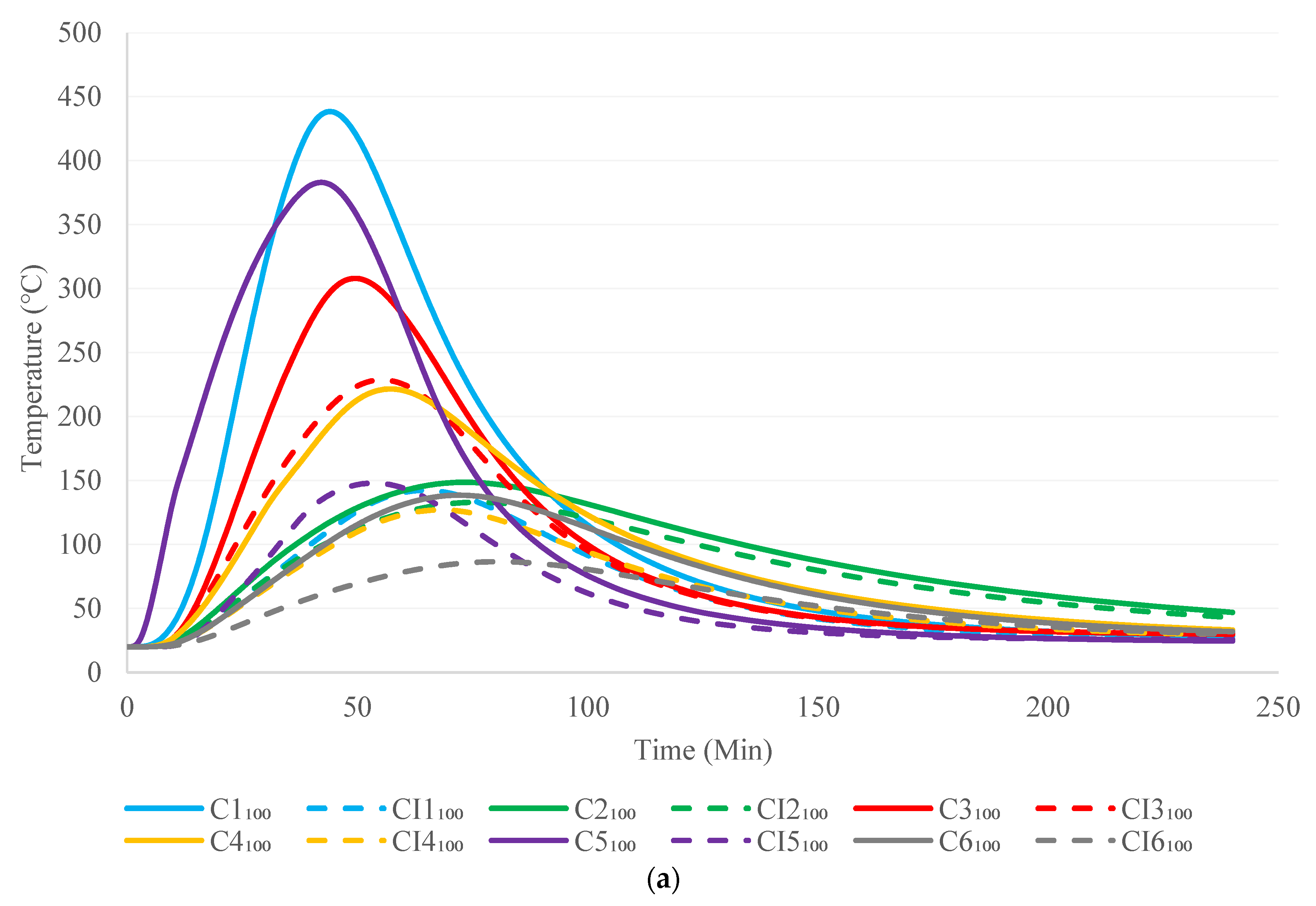
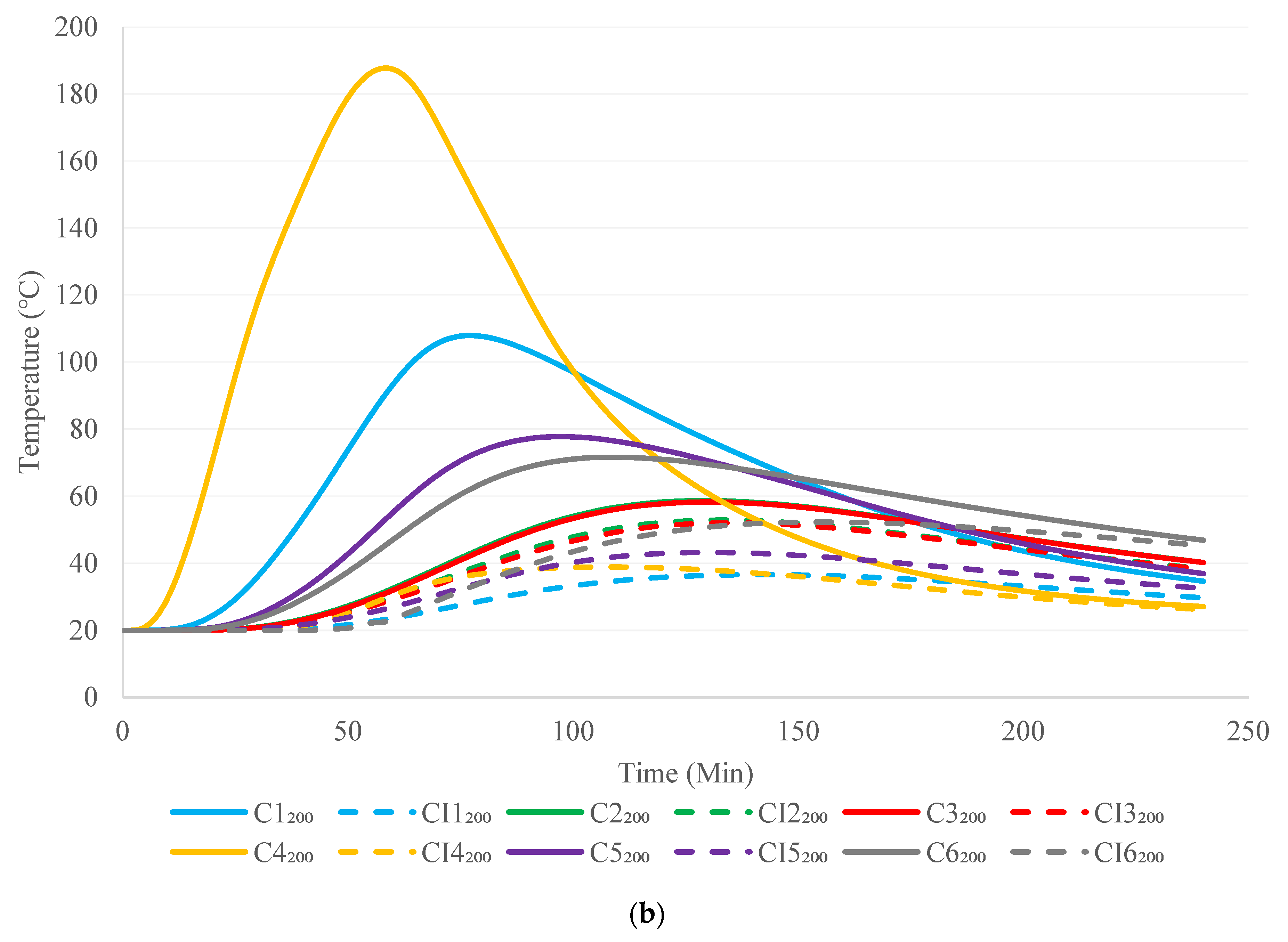
The time–temperature changes of the 3D-printed concrete wall panels on the unexposed side in the rapid fire scenario are shown in Figure 11a,b. The impact of rapid fire was identified as being critical throughout the earliest 1-h time duration, and it was observed to result in a rapid temperature increment. Afterwards, since the real fire curve maintained a declining phase, a considerable temperature reduction was identified. The rapid-fire situation revealed the lower fire resistance rate for the cavity wall configurations with 100 mm thickness single-row arrangements, and hence, their results contrasted with those of the other three fire conditions in terms of showing higher severity. However, among the 100 mm wall panels, the triangular sectional wall C3, and amongst the 200 mm walls, C4 with a double lattice row arrangement showed irregular variation. These contradictory observations must be further investigated. Furthermore, it should be remarked that both the cavity C2 triangular wall and the C6 cellular wall did not achieve the insulation failure fire rating temperature of 160 °C within the 4 h of rapid-fire contact. Similarly, for the 200 mm wall panels, insulation failure was not discovered, apart from in the cavity wall panel C4. It is evident that the use of the mineral wool-infilled cavity walls resulted in improved fire performance as compared to that of the other cavity walls regardless of the cross-sectional arrangements and wall thicknesses.

5.4. Prolonged Fire

Figure 12a,b illustrate the unexposed surface temperature–time change of 3D-printed concrete walls exposed to the prolonged fire condition. The temperature increase was considerably greater at the early 2-h period, as evidenced by the temperature drop during the latter stages. It demonstrated a moderately better insulation fire rating compared to hydrocarbon and rapid fire and as expected, indicated a reduced value, which was associated with the standard fire situation. The prolonged fire scenario showed similar performance in terms of the time–temperature profiles of rapid fire for all the different cross sections. The CI6 cellular and CI1 truss wall panels displayed higher performance under fire at 100 mm and 200 mm thickness, respectively, with mineral wool cavity insulation. It is notable that the C2, C3, C5, and C6 cavity walls with 200 mm thickness did not attain the temperature of 160 °C within 4 h. In addition, for all of the 200 mm mineral wool insulated wall panels, no insulation failure was detected.

5.5. Effect of Individual Real Fire on Different Wall Configurations

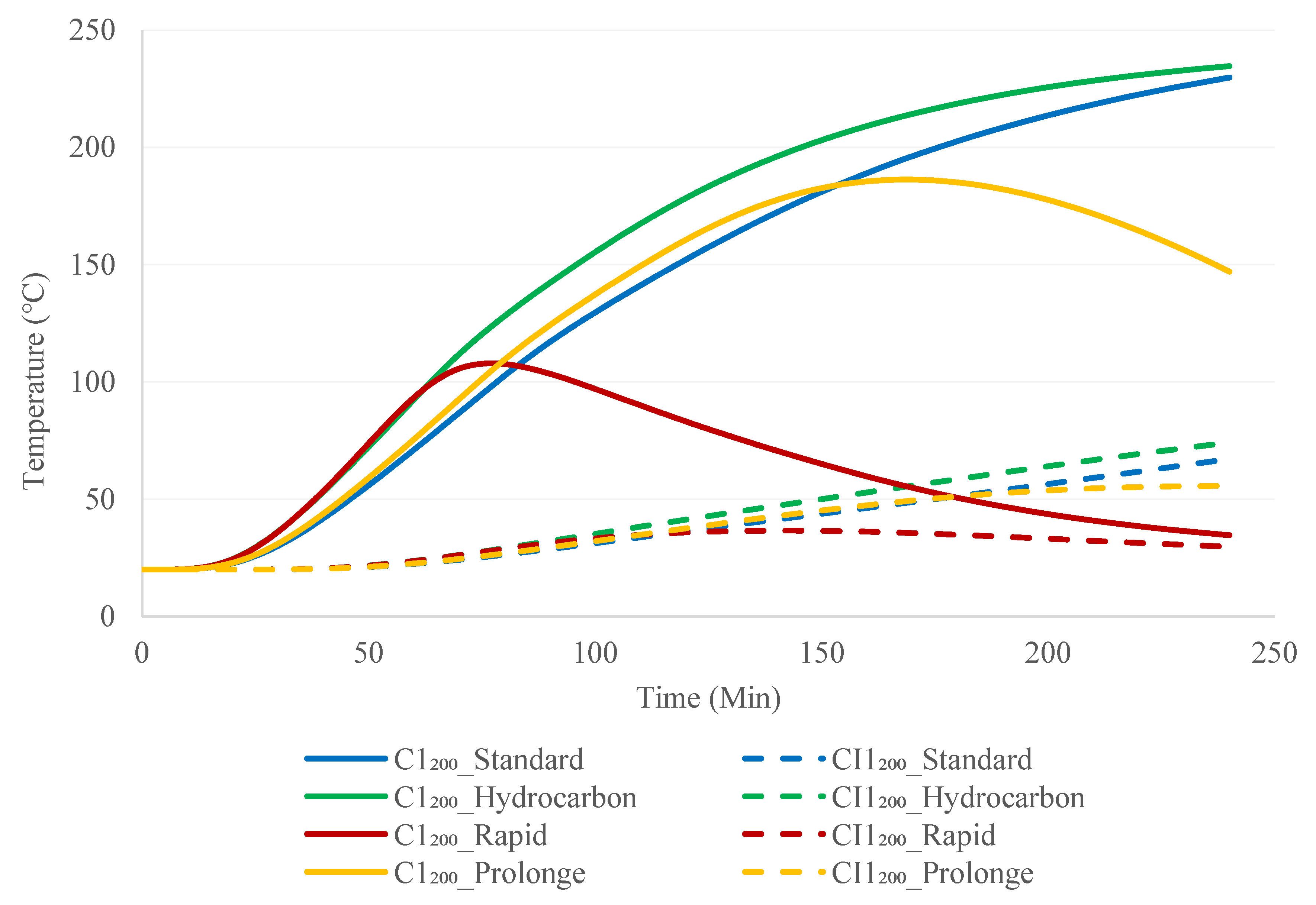
The insulation fire rating of the wall configurations obtained from the produced time–temperature outlines under real fire circumstances are presented in Table 5 and Table 6. These results reveal that relatively similar fire-resisting times were achieved for the standard and prolonged fire situations, whilst the fire-resisting times for the hydrocarbon and rapid fires were also quite similar. This shows that the attributes of the fire curves with the maximum fire temperature and the subsequent time, as well as the rate of reduction, considerably influenced the temperature of the unexposed 3D-printed concrete walls. Moreover, the double-row configurations showed less enhancement in terms of fire performance with insulation, irrespective of the cross-sectional arrangements (Figure 13). However, the wall panels with single-row configurations showed superior fire performance when mineral wool insulation was incorporated (Figure 14). These phenomena can be explained by the fact that the void area was much large in those walls, in addition to the cavity radiation effect and the impact of insulation being different.
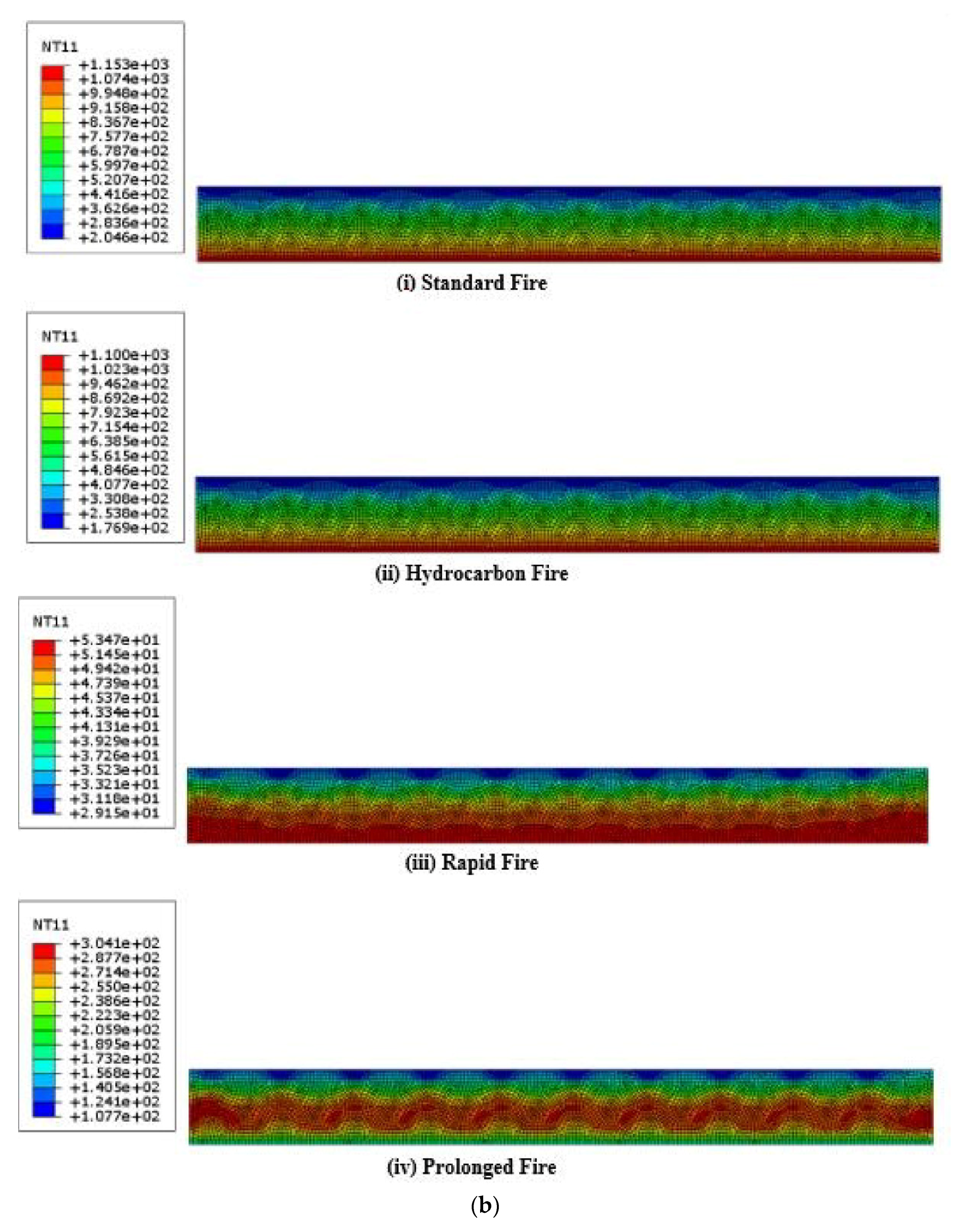
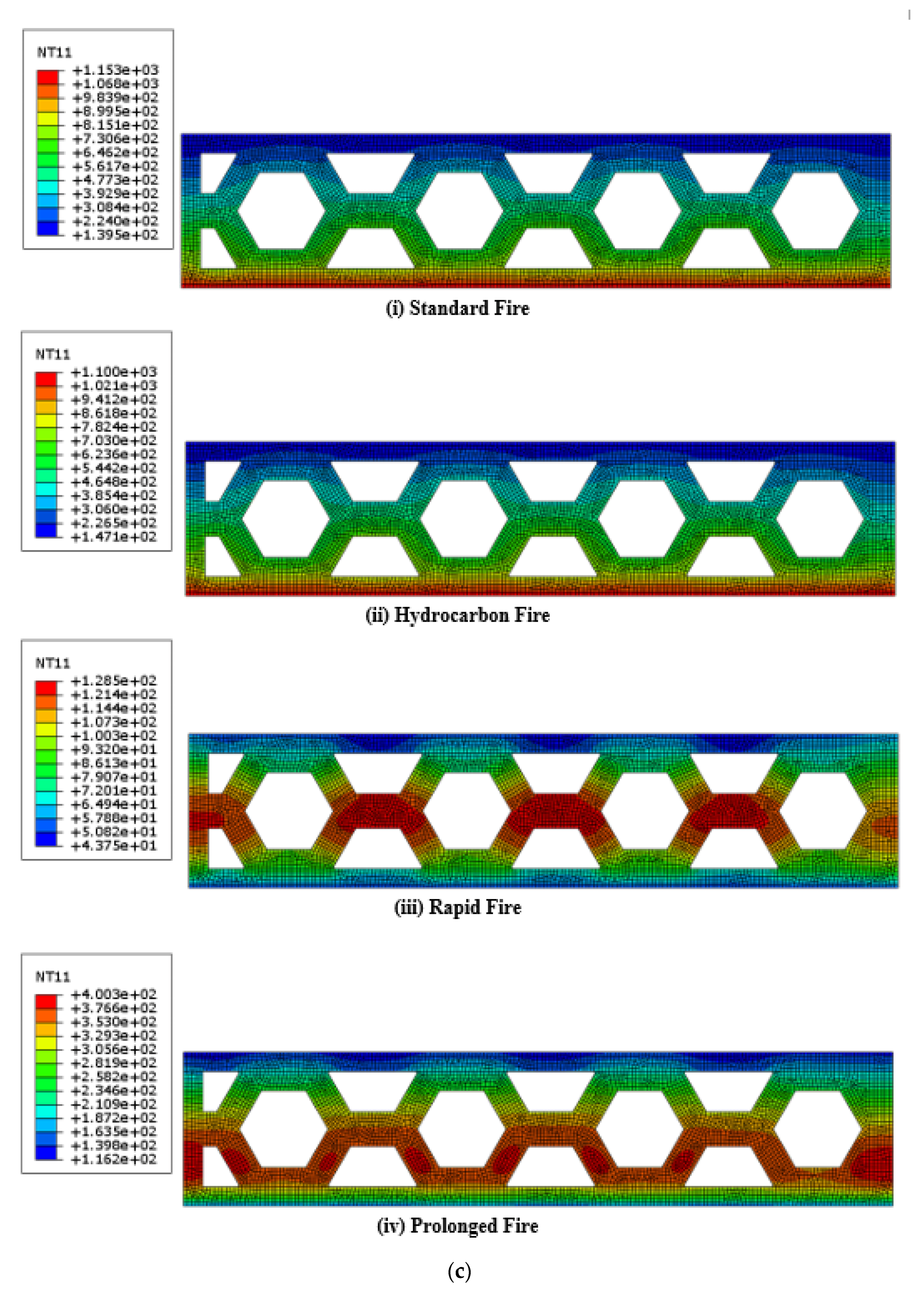
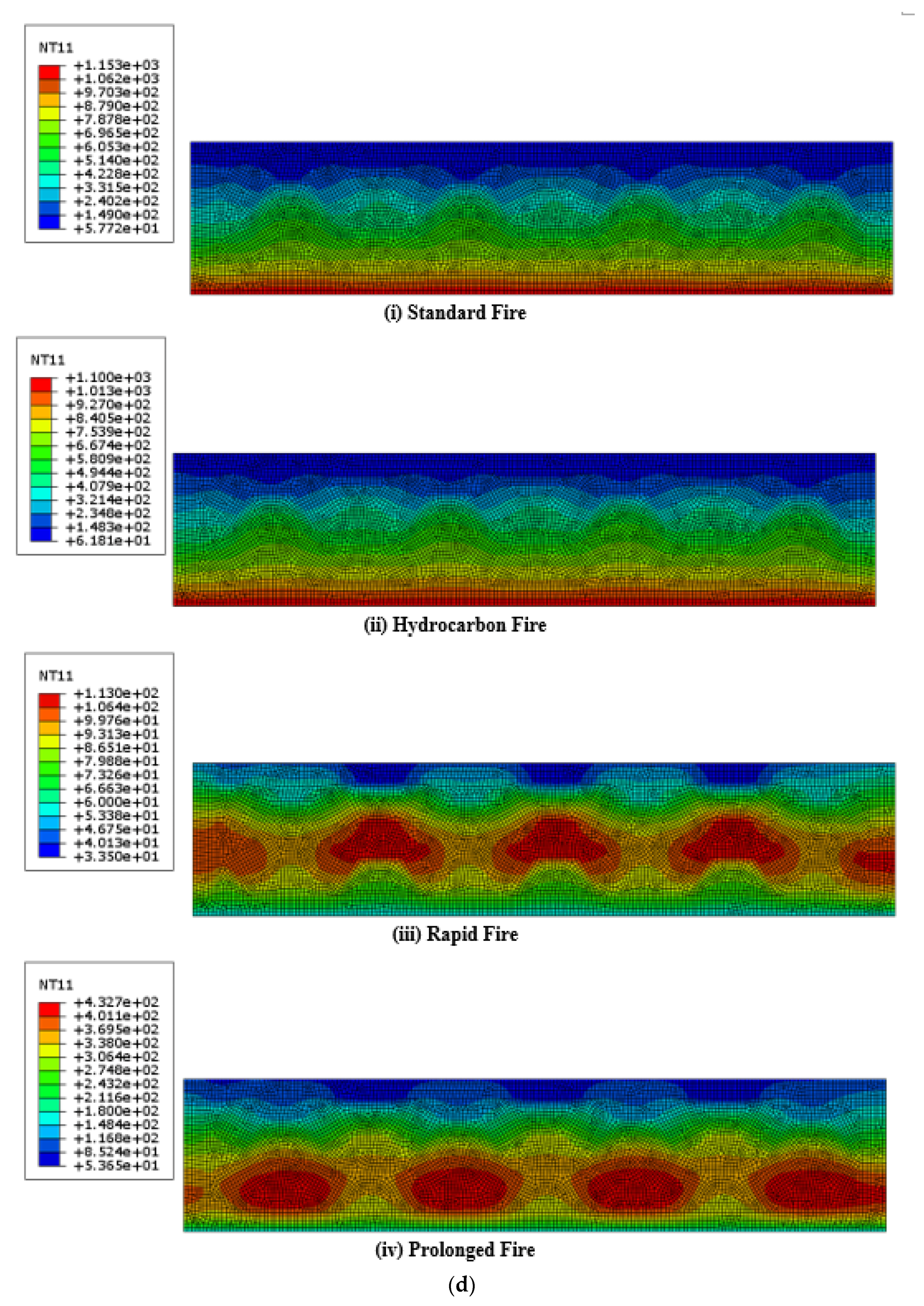
Figure 15a–d illustrate the temperature distribution obtained from finite element analysis for the cellular cross-sectional wall configurations (C6) after 4 h of heat transfer under the considered fire scenarios. A non-uniform temperature distribution could be observed due to the integration of the insulation material. Moreover, the severity of rapid fire and prolonged fire in terms of their effects on the wall panels, as compared to the standard and hydrocarbon fire curves, could be observed clearly through this temperature distribution.

6. Conclusions

The existing research on 3DCP is primarily concentrated on materials, automation, and structural strength, and thus, there are still many characteristics related to fire behaviour and thermal efficiency that need further study. Furthermore, the numerical simulation of the 3DCP method is a quite new research area in the field of dynamic growth, and many questions remain. Therefore, this paper presented the findings of numerical studies on the fire performance of bio-inspired 3D-printed concrete walls that involved both cavity walls and cavity-insulated wall configurations. The effects of the wall thickness, cross-sectional arrangements, and cavity insulation on the insulation fire rating under different realistic fire scenarios were examined. Finally, several conclusions can be described as follows:
  • Non-load-bearing 3D-printed concrete cavity walls showed a lower insulation failure fire rating, whereas 3D-printed concrete cavity walls insulated with mineral wool had an excellent fire rating.
  • The individual fire curves considerably affected the unexposed surface temperature increase in wall panels. The outcomes prove that rapid fire and prolonged fire are crucial in terms of the fire performance associated with standard and hydrocarbon fire curves.
  • Ample enhancement on fire performance was observed when the wall thicknesses of 3D-printed concrete walls were increased from 100 mm to 200 mm.
  • The cellular configuration (C6) showed greater fire performance with mineral wool insulation compared to the other wall configurations, regardless of the fire scenario.
  • The fluctuating fire behaviour of these wall configurations needs to be investigated further considering the measured thermal properties of 3D-printable concrete at higher temperatures and with the incorporation of structural failures.

Author Contributions

Conceptualization: K.P.; performed the numerical simulations and analysis: I.U. and T.S.; results interpretation: T.S., I.U. and K.P.; writing—original draft preparation: T.S., I.U. and P.G.; writing—review and editing: T.S., I.U., P.G., K.P., B.N. and K.D.T.; visualization: T.S. and D.N.; super-vision: K.P. and B.N. All authors have read and agreed to the published version of the manuscript.

Funding

This research study is funded by Research Development Fund (RDF), Northumbria University and received no external funding.

Institutional Review Board Statement

Not applicable.

Informed Consent Statement

Not applicable.

Data Availability Statement

Not applicable.

Acknowledgments

The authors would like to acknowledge the financial and technical support of Northumbria University and University of Sri Jayewardenepura.

Conflicts of Interest

The authors declare no conflict of interest.

References

  1. Furet, B.; Poullain, P.; Garnier, S. 3D printing for construction based on a complex wall of polymer-foam and concrete. Addit. Manuf. 2019, 28, 58–64. [Google Scholar] [CrossRef]
  2. Adaloudis, M.; Bonnin Roca, J. Sustainability tradeoffs in the adoption of 3D Concrete Printing in the construction industry. J. Clean. Prod. 2021, 307, 127201. [Google Scholar] [CrossRef]
  3. Khan, M.S.; Sanchez, F.; Zhou, H. 3-D printing of concrete: Beyond horizons. Cem. Concr. Res. 2020, 133, 106070. [Google Scholar] [CrossRef]
  4. Xiao, J.; Ji, G.; Zhang, Y.; Ma, G.; Mechtcherine, V.; Pan, J.; Wang, L.; Ding, T.; Duan, Z.; Du, S. Large-scale 3D printing concrete technology: Current status and future opportunities. Cem. Concr. Compos. 2021, 122, 104115. [Google Scholar] [CrossRef]
  5. Pessoa, S.; Guimarães, A.S.; Lucas, S.S.; Simões, N. 3D printing in the construction industry—A systematic review of the thermal performance in buildings. Renew. Sustain. Energy Rev. 2021, 141, 110794. [Google Scholar] [CrossRef]
  6. Menna, C.; Mata-Falcón, J.; Bos, F.P.; Vantyghem, G.; Ferrara, L.; Asprone, D.; Salet, T.; Kaufmann, W. Opportunities and challenges for structural engineering of digitally fabricated concrete. Cem. Concr. Res. 2020, 133, 106079. [Google Scholar] [CrossRef]
  7. Khan, S.A.; Koç, M.; Al-Ghamdi, S.G. Sustainability assessment, potentials and challenges of 3D printed concrete structures: A systematic review for built environmental applications. J. Clean. Prod. 2021, 303, 127027. [Google Scholar] [CrossRef]
  8. Ooms, T.; Vantyghem, G.; Van Coile, R.; De Corte, W. A parametric modelling strategy for the numerical simulation of 3D concrete printing with complex geometries. Addit. Manuf. 2021, 38, 101743. [Google Scholar] [CrossRef]
  9. Mechtcherine, V.; Bos, F.P.; Perrot, A.; da Silva, W.R.L.; Nerella, V.N.; Fataei, S.; Wolfs, R.J.M.; Sonebi, M.; Roussel, N. Extrusion-based additive manufacturing with cement-based materials—Production steps, processes, and their underlying physics: A review. Cem. Concr. Res. 2020, 132, 106037. [Google Scholar] [CrossRef]
  10. Paul, S.C.; van Zijl, G.P.A.G.; Tan, M.J.; Gibson, I. A review of 3D concrete printing systems and materials properties: Current status and future research prospects. Rapid Prototyp. J. 2018, 24, 784–798. [Google Scholar] [CrossRef] [Green Version]
  11. Yazyev, B.; Karpova, E.; Skripkiunas, G.; Sedova, A.; Tsimbalyuk, Y. Additive manufacturing of concrete wall structures. E3S Web Conf. 2021, 281, 03007. [Google Scholar] [CrossRef]
  12. Nguyen-Van, V.; Panda, B.; Zhang, G.; Nguyen-Xuan, H.; Tran, P. Digital design computing and modelling for 3-D concrete printing. Autom. Constr. 2021, 123, 103529. [Google Scholar] [CrossRef]
  13. Ahmed, A.; Azam, A.; Aslam Bhutta, M.M.; Khan, F.A.; Aslam, R.; Tahir, Z. Discovering the technology evolution pathways for 3D printing (3DP) using bibliometric investigation and emerging applications of 3DP during COVID-19. Clean. Environ. Syst. 2021, 3, 100042. [Google Scholar] [CrossRef]
  14. Luhar, S.; Suntharalingam, T.; Navaratnam, S.; Luhar, I.; Thamboo, J.; Poologanathan, K.; Gatheeshgar, P. Sustainable and Renewable Bio-Based Natural Fibres and Its Application for 3D Printed Concrete: A Review. Sustainability 2020, 12, 10485. [Google Scholar] [CrossRef]
  15. Delgado Camacho, D.; Clayton, P.; O’Brien, W.J.; Seepersad, C.; Juenger, M.; Ferron, R.; Salamone, S. Applications of additive manufacturing in the construction industry—A forward-looking review. Autom. Constr. 2018, 89, 110–119. [Google Scholar] [CrossRef]
  16. Suntharalingam, T.; Gatheeshgar, P.; Upasiri, I.; Poologanathan, K.; Nagaratnam, B.; Rajanayagam, H.; Navaratnam, S. Numerical Study of Fire and Energy Performance of Innovative Light-Weight 3D Printed Concrete Wall Configurations in Modular Building System. Sustainability 2021, 13, 2314. [Google Scholar] [CrossRef]
  17. Suntharalingam, T.; Upasiri, I.; Gatheeshgar, P.; Poologanathan, K.; Nagaratnam, B.; Santos, P.; Rajanayagam, H. Energy Performance of 3D-Printed Concrete Walls: A Numerical Study. Buildings 2021, 11, 432. [Google Scholar] [CrossRef]
  18. Hayes, S.; Desha, C.; Baumeister, D. Learning from nature—Biomimicry innovation to support infrastructure sustainability and resilience. Technol. Forecast. Soc. Chang. 2020, 161, 120287. [Google Scholar] [CrossRef]
  19. du Plessis, A.; Broeckhoven, C.; Yadroitsava, I.; Yadroitsev, I.; Hands, C.H.; Kunju, R.; Bhate, D. Beautiful and Functional: A Review of Biomimetic Design in Additive Manufacturing. Addit. Manuf. 2019, 27, 408–427. [Google Scholar] [CrossRef]
  20. Islam, M.K.; Hazell, P.J.; Escobedo, J.P.; Wang, H. Biomimetic armour design strategies for additive manufacturing: A review. Mater. Des. 2021, 205, 109730. [Google Scholar] [CrossRef]
  21. Jia, Z.; Wang, L. 3D printing of biomimetic composites with improved fracture toughness. Acta Mater. 2019, 173, 61–73. [Google Scholar] [CrossRef]
  22. Ko, K.; Jin, S.; Lee, S.E.; Lee, I.; Hong, J.-W. Bio-inspired bimaterial composites patterned using three-dimensional printing. Compos. Part B: Eng. 2019, 165, 594–603. [Google Scholar] [CrossRef]
  23. du Plessis, A.; Babafemi, A.J.; Paul, S.C.; Panda, B.; Tran, J.P.; Broeckhoven, C. Biomimicry for 3D concrete printing: A review and perspective. Addit. Manuf. 2021, 38, 101823. [Google Scholar] [CrossRef]
  24. Wang, L.; Jiang, H.; Li, Z.; Ma, G. Mechanical behaviors of 3D printed lightweight concrete structure with hollow section. Arch. Civ. Mech. Eng. 2020, 20, 1–17. [Google Scholar] [CrossRef] [Green Version]
  25. Panda, B.; Leite, M.; Biswal, B.B.; Niu, X.; Garg, A. Experimental and numerical modelling of mechanical properties of 3D printed honeycomb structures. Measurement 2018, 116, 495–506. [Google Scholar] [CrossRef]
  26. Moini, M.; Olek, J.; Youngblood, J.P.; Magee, B.; Zavattieri, P.D. Additive Manufacturing and Performance of Architectured Cement-Based Materials. Adv. Mater. 2018, 30, e1802123. [Google Scholar] [CrossRef] [PubMed] [Green Version]
  27. Rashid, M.H.; Molla, M.; Taki, I.M. Effect of Elevated Temperature on Bond Strength of Concrete. In Materials Science Forum; Trans Tech Publications Ltd.: Freinbach, Switzerland, 2019; Volume 972, pp. 26–33. [Google Scholar]
  28. Upasiri, I.R.; Konthesigha, K.M.C.; Nanayakkara, S.M.A.; Poologanathan, K.; Gatheeshgar, P.; Nuwanthika, D. Finite element analysis of lightweight composite sandwich panels exposed to fire. J. Build. Eng. 2021, 40, 102329. [Google Scholar] [CrossRef]
  29. Mohd Ali, A.Z.; Sanjayan, J.; Guerrieri, M. Performance of geopolymer high strength concrete wall panels and cylinders when exposed to a hydrocarbon fire. Constr. Build. Mater. 2017, 137, 195–207. [Google Scholar] [CrossRef]
  30. Suntharalingam, T.; Gatheeshgar, P.; Upasiri, I.; Poologanathan, K.; Nagaratnam, B.; Corradi, M.; Nuwanthika, D. Fire performance of innovative 3D printed concrete composite wall panels—A Numerical Study. Case Stud. Constr. Mater. 2021, 15, e00586. [Google Scholar] [CrossRef]
  31. del Coz-Díaz, J.J.; Martínez-Martínez, J.E.; Alonso-Martínez, M.; Álvarez Rabanal, F.P. Comparative study of LightWeight and Normal Concrete composite slabs behaviour under fire conditions. Eng. Struct. 2020, 207, 110196. [Google Scholar] [CrossRef]
  32. Banerji, S.; Kodur, V.; Solhmirzaei, R. Experimental behavior of ultra high performance fiber reinforced concrete beams under fire conditions. Eng. Struct. 2020, 208, 110316. [Google Scholar] [CrossRef]
  33. Weerasinghe, P.; Nguyen, K.; Mendis, P.; Guerrieri, M. Large-scale experiment on the behaviour of concrete flat slabs subjected to standard fire. J. Build. Eng. 2020, 30, 101255. [Google Scholar] [CrossRef]
  34. Cao, V.D.; Bui, T.Q.; Kjøniksen, A.-L. Thermal analysis of multi-layer walls containing geopolymer concrete and phase change materials for building applications. Energy 2019, 186, 115792. [Google Scholar] [CrossRef]
  35. Steau, E.; Mahendran, M.; Poologanathan, K. Elevated temperature thermal properties of carbon steels used in cold-formed light gauge steel frame systems. J. Build. Eng. 2020, 28, 101074. [Google Scholar] [CrossRef]
  36. Gunalan, S.; Mahendran, M. Fire performance of cold-formed steel wall panels and prediction of their fire resistance rating. Fire Saf. J. 2014, 64, 61–80. [Google Scholar] [CrossRef] [Green Version]
  37. Steau, E.; Mahendran, M.; Poologanathan, K. Experimental study of fire resistant board configurations under standard fire conditions. Fire Saf. J. 2020, 116, 103153. [Google Scholar] [CrossRef]
  38. Gunalan, S.; Kolarkar, P.; Mahendran, M. Experimental study of load bearing cold-formed steel wall systems under fire conditions. Thin-Walled Struct. 2013, 65, 72–92. [Google Scholar] [CrossRef] [Green Version]
  39. Ariyanayagam, A.; Mahendran, M. Experimental Study of Load-Bearing Cold-Formed Steel Walls Exposed to Realistic Design Fires. J. Struct. Fire Eng. 2014, 5, 291–330. [Google Scholar] [CrossRef] [Green Version]
  40. Ariyanayagam, A.D.; Mahendran, M. Fire design rules for load bearing cold-formed steel frame walls exposed to realistic design fire curves. Fire Saf. J. 2015, 77, 1–20. [Google Scholar] [CrossRef] [Green Version]
  41. Ariyanayagam, A.D.; Mahendran, M. Influence of cavity insulation on the fire resistance of light gauge steel framed walls. Constr. Build. Mater. 2019, 203, 687–710. [Google Scholar] [CrossRef]
  42. Ariyanayagam, A.D.; Mahendran, M. Experimental study of non-load bearing light gauge steel framed walls in fire. J. Constr. Steel Res. 2018, 145, 529–551. [Google Scholar] [CrossRef] [Green Version]
  43. Dias, Y.; Keerthan, P.; Mahendran, M. Fire performance of steel and plasterboard sheathed non-load bearing LSF walls. Fire Saf. J. 2019, 103, 1–18. [Google Scholar] [CrossRef]
  44. Kesawan, S.; Mahendran, M. Fire tests of load-bearing LSF walls made of hollow flange channel sections. J. Constr. Steel Res. 2015, 115, 191–205. [Google Scholar] [CrossRef]
  45. Kesawan, S.; Mahendran, M. Fire design rules for LSF walls made of hollow flange channel sections. Thin-Walled Struct. 2016, 107, 300–314. [Google Scholar] [CrossRef]
  46. Perera, D.; Poologanathan, K.; Gillie, M.; Gatheeshgar, P.; Sherlock, P.; Nanayakkara, S.M.A.; Konthesingha, K.M.C. Fire performance of cold, warm and hybrid LSF wall panels using numerical studies. Thin-Walled Struct. 2020, 157, 107109. [Google Scholar] [CrossRef]
  47. Ariyanayagam, A.D.; Mahendran, M. Numerical modelling of load bearing light gauge steel frame wall systems exposed to realistic design fires. Thin-Walled Struct. 2014, 78, 148–170. [Google Scholar] [CrossRef] [Green Version]
  48. Gunalan, S.; Mahendran, M. Finite element modelling of load bearing cold-formed steel wall systems under fire conditions. Eng. Struct. 2013, 56, 1007–1027. [Google Scholar] [CrossRef] [Green Version]
  49. Keerthan, P.; Mahendran, M. Thermal Performance of Composite Panels Under Fire Conditions Using Numerical Studies: Plasterboards, Rockwool, Glass Fibre and Cellulose Insulations. Fire Technol. 2012, 49, 329–356. [Google Scholar] [CrossRef] [Green Version]
  50. Suntharalingam, T.; Upasiri, I.; Gatheeshgar, P.; Poologanathan, K.; Nagaratnam, B.; Rajanayagam, H.; Navaratnam, S. Fire resistance of 3D printed concrete composite wall panels exposed to various fire scenarios. J. Struct. Fire Eng. 2021. ahead-of-print. [Google Scholar] [CrossRef]
  51. Xiao, J.; Han, N.; Zhang, L.; Zou, S. Mechanical and microstructural evolution of 3D printed concrete with polyethylene fiber and recycled sand at elevated temperatures. Constr. Build. Mater. 2021, 293, 123524. [Google Scholar] [CrossRef]
  52. Weng, Y.; Li, M.; Liu, Z.; Lao, W.; Lu, B.; Zhang, D.; Tan, M.J. Printability and fire performance of a developed 3D printable fibre reinforced cementitious composites under elevated temperatures. Virtual Phys. Prototyp. 2018, 14, 284–292. [Google Scholar] [CrossRef]
  53. Cicione, A.; Kruger, J.; Walls, R.S.; Van Zijl, G. An experimental study of the behavior of 3D printed concrete at elevated temperatures. Fire Saf. J. 2021, 120, 103075. [Google Scholar] [CrossRef]
  54. Cicione, A.; Mazolwana, K.; Kruger, J.; Walls, R.; Sander, Z.; Van Zijl, G. Effect of transverse and longitudinal confinement on the interlayer bond in 3D printed concrete at elevated temperatures: An experimental study. In Proceedings of Proceedings of the 11th International Conference on Structures in Fire (SiF2020), Brisbane, Australia, 30 November–2 December 2020. [Google Scholar]
  55. Sun, J.; Xiao, J.; Li, Z.; Feng, X. Experimental study on the thermal performance of a 3D printed concrete prototype building. Energy Build. 2021, 241, 110965. [Google Scholar] [CrossRef]
  56. Kaszynka, M.; Olczyk, N.; Techman, M.; Skibicki, S.; Zielinski, A.; Filipowicz, K.; Wroblewski1, T.; Hoffmann, M. Thermal-humidity parameters of 3D printed wall. In IOP Conference Series: Materials Science and Engineering; IOP Publishing: Bristol, UK, 2019; Volume 471, p. 082018. [Google Scholar]
  57. Yang, S.; Wi, S.; Park, J.H.; Cho, H.M.; Kim, S. Novel proposal to overcome insulation limitations due to nonlinear structures using 3D printing: Hybrid heat-storage system. Energy Build. 2019, 197, 177–187. [Google Scholar] [CrossRef]
  58. Alchaar, A.S.; Al-Tamimi, A.K. Mechanical properties of 3D printed concrete in hot temperatures. Constr. Build. Mater. 2021, 266, 120991. [Google Scholar] [CrossRef]
  59. Marais, H.; Christen, H.; Cho, S.; De Villiers, W.; Van Zijl, G. Computational assessment of thermal performance of 3D printed concrete wall structures with cavities. J. Build. Eng. 2021, 41, 102431. [Google Scholar] [CrossRef]
  60. Mahadevan, M.; Francis, A.; Thomas, A. A simulation-based investigation of sustainability aspects of 3D printed structures. J. Build. Eng. 2020, 32, 101735. [Google Scholar] [CrossRef]
  61. Hibbett; Karlsson; Sorensen. ABAQUS/Standard: User’s Manual; Dassault Systèmes Simulia Corp.: Providence, RI, USA, 1998; Volume 1. [Google Scholar]
  62. EN 1993-1-2; Eurocode 3: Design of Steel Structures—Part 1-2: General Rules—Structural Fire Design. European Committee for Standardisation: London, UK, 2007.
  63. Upasiri, I.; Konthesingha, C.; Nanayakkara, A.; Poologanathan, K.; Nagaratnam, B.; Perampalam, G. Evaluation of fire performance of lightweight concrete wall panels using finite element analysis. J. Struct. Fire Eng. 2021, 12, 328–362. [Google Scholar] [CrossRef]
  64. Upasiri, I.; Konthesingha, C.; Poologanathan, K.; Nanayakkara, A.; Nagaratnam, B. Review on Fire Performance of Cellular Lightweight Concrete. In ICSBE 2018; Dissanayake, R., Mendis, P., Eds.; Springer: Singapore, 2020; pp. 470–478. [Google Scholar]
  65. Tan, X.; Chen, W.; Wang, J.; Yang, D.; Qi, X.; Ma, Y.; Wang, X.; Ma, S.; Li, C. Influence of high temperature on the residual physical and mechanical properties of foamed concrete. Constr. Build. Mater. 2017, 135, 203–211. [Google Scholar] [CrossRef]
  66. Ramamurthy, K.; Kunhanandan Nambiar, E.K.; Indu Siva Ranjani, G. A classification of studies on properties of foam concrete. Cem. Concr. Compos. 2009, 31, 388–396. [Google Scholar] [CrossRef]
  67. EN 1991-1-2; Eurocode 1: Actions on Structures—Part 1–2: General Actions—Actions on Structures Exposed to Fire. British Standards: London, UK, 1991.
  68. American Society for Testing and Materials. ASTM E119: Standard Test Methods for Fire Tests of Building Construction and Materials; ASTM: West Conshohocken, PA, USA, 2021. [Google Scholar] [CrossRef]
  69. Ariyanayagam, A.D.; Mahendran, M. Development of realistic design fire time-temperature curves for the testing of cold-formed steel wall systems. Front. Struct. Civ. Eng. 2014, 8, 427–447. [Google Scholar] [CrossRef] [Green Version]
Figure 1. Three-dimensional printed samples: (a) cellular; (b) triangular; (c) truss; (d) lattice [24] (unit: mm).
Buildings 12 00111 g001
Figure 2. (a) Honeycomb; (b) cellular panel; (c) Bouligand shape (2°); (d) Bouligand shape (45°) [26].
Buildings 12 00111 g002
Figure 3. Thermal properties of 3D-printed concrete with increasing temperature: (a) relative density; (b) thermal conductivity; (c) specific heat [30].
Buildings 12 00111 g003
Figure 4. Thermal conductivity of mineral wool [49].
Buildings 12 00111 g004
Figure 5. Geometry of wall configuration: (a) with cavity; (b) with cavity insulation.
Buildings 12 00111 g005
Figure 6. Abaqus modelling images: (a) boundary condition; (b) cavity radiation; (c) surface interaction; (d) meshing.
Buildings 12 00111 g006
Figure 7. Standard fire (ISO 834) and real fire curves.
Buildings 12 00111 g007
Figure 8. Boundary conditions applied on the developed model.
Buildings 12 00111 g008
Figure 9. (a) Unexposed surface temperature variation of 100 mm wall configurations subjected to standard fire. (b) Unexposed surface temperature variation of 200 mm wall configurations subjected to standard fire.
Buildings 12 00111 g009aBuildings 12 00111 g009b
Figure 10. (a) Unexposed surface temperature variation of 100 mm wall configurations subjected to hydrocarbon fire. (b) Unexposed surface temperature variation of 200 mm wall configurations subjected to hydrocarbon fire.
Buildings 12 00111 g010
Figure 11. (a) Unexposed surface temperature variation of 100 mm wall configurations subjected to rapid fire. (b) Unexposed surface temperature variation of 200 mm wall configurations subjected to rapid fire.
Buildings 12 00111 g011aBuildings 12 00111 g011b
Figure 12. (a) Unexposed surface temperature variation of 100 mm wall configurations subjected to prolonged fire. (b) Unexposed surface temperature variation of 200 mm wall configurations subjected to prolonged fire.
Buildings 12 00111 g012
Figure 13. Unexposed surface temperature changes of 100mm wall configurations C2 and CI2 under different fire conditions.
Buildings 12 00111 g013
Figure 14. Unexposed surface temperature changes of 200mm wall configurations C1 and CI1 under different fire conditions.
Buildings 12 00111 g014
Figure 15. (a) Temperature distribution of C6100 wall panel. (b) Temperature distribution of CI6100 wall panel. (c) Temperature distribution of C6200 wall panel. (d) Temperature contours of CI6200 wall panel.
Buildings 12 00111 g015aBuildings 12 00111 g015bBuildings 12 00111 g015cBuildings 12 00111 g015d
Table 1. Parametric fire curves.
Fire CurveRapid FireProlonged Fire
Opening Factor (m1/2)0.080.03
Area of Ventilation (m2)2.851.44
Compartment’s Thermal Inertia (J/m2 S1/2 K)715702
Table 2. Two-dimensional FEA Validation of 3DPC and C3CPD Samples [30].
Comparison of Experimental Results of 3DPC Samples with 2D FEA in AbaqusComparison of Experimental Results of C3DPC Samples with 2D FEA in Abaqus
Buildings 12 00111 i001
3DPC(S1)
Buildings 12 00111 i002
C3DPC(S1)
Buildings 12 00111 i003
3DPC(S2)
Buildings 12 00111 i004
C3DPC(S2)
Buildings 12 00111 i005
3DPC(S3)
Buildings 12 00111 i006
C3DPC(S3)
Table 3. Different cross-sectioned 3D-printed concrete wall configurations.
Wall Configuration (1 m Length)100 mm (12 mm Layer)200 mm (25 mm Layer)
C1
Truss
Buildings 12 00111 i007 Buildings 12 00111 i008
C2
Triangular
Buildings 12 00111 i009 Buildings 12 00111 i010
C3
Triangular
Buildings 12 00111 i011 Buildings 12 00111 i012
C4
Lattice
Buildings 12 00111 i013 Buildings 12 00111 i014
C5
Lattice
Buildings 12 00111 i015 Buildings 12 00111 i016
C6
Cellular
Buildings 12 00111 i017 Buildings 12 00111 i018
Table 4. Outline of parametric study.
Fire ScenarioDensity
(kg/m3)
Thickness of the Wall (mm)Wall ConfigurationModels
ISO Fire2400 100
200
C1, C2, C3, C4, C5, C6
CI1, CI2, CI3, CI4, CI5, CI6
24
Hydrocarbon2400 100
200
C1, C2, C3, C4, C5, C6
CI1, CI2, CI3, CI4, CI5, CI6
24
Rapid Fire2400 100
200
C1, C2, C3, C4, C5, C6
CI1, CI2, CI3, CI4, CI5, CI6
24
Prolonged Fire2400 100
200
C1, C2, C3, C4, C5, C6
CI1, CI2, CI3, CI4, CI5, CI6
24
Total 96
Table 5. Insulation fire ratings for 3D-printed concrete walls (100 mm series).
ConfigurationsInsulation Failure Time under Different Fire Exposure (min)
Standard FireHydrocarbon FireRapid FireProlonged Fire
Cavity wallsC110037252029
C21009775-82
C310095742735
C410053383625
C510020121217
C610014478-106
Mineral wool-infilled wallsCI110010470-92
CI210012093--
CI3100116893344
CI410012891-76
CI510011261-94
CI6100----
Table 6. Insulation fire ratings for 3D-printed concrete cavity walls (200 mm series).
ConfigurationsInsulation Failure Time under Different Fire Exposure (min)
Standard FireHydrocarbon FireRapid FireProlonged Fire
Cavity wallsC1200125101-119
C2200----
C3200----
C420060444256
C5200187159--
C6200----
Publisher’s Note: MDPI stays neutral with regard to jurisdictional claims in published maps and institutional affiliations.