Article

Tuned-Mass-Damper-Inerter Performance Evaluation and Optimal Design for Transmission Line under Harmonic Excitation

1
School of Civil Engineering and Architecture, Chongqing University of Science & Technology, Chongqing 401331, China
2
Chongqing Key Laboratory of Energy Engineering Mechanics & Disaster Prevention and Mitigation, Chongqing 401331, China
*
Author to whom correspondence should be addressed.
Buildings 2022, 12(4), 435; https://doi.org/10.3390/buildings12040435
Submission received: 11 March 2022 / Revised: 28 March 2022 / Accepted: 31 March 2022 / Published: 2 April 2022

Abstract

:
To investigate vibration control and optimal design of transmission lines with tuned-mass-damper-inerter (TMDI), the motion equation of transmission lines with TMDI is established in the paper, and the closed-form solutions of the response spectrum of transmission line displacement are derived by the frequency domain analysis method. The design parameters of TMDI are optimized by fixed-point theory, and the vibration control performance of TMDI is discussed. The results show that the increase in apparent mass ratio has a positive effect on the vibration control performance of TMDI; the vibration control performance is greatly affected by frequency ratio and limited by damping ratio; the increase in both mass ratio and apparent mass ratio reduces the peak values of the displacement response spectra of transmission line with TMDI; however, blindly increasing the apparent mass and mass ratio (β > 0.2 or μ > 0.4) has a limited effect on improving the vibration control performance of TMDI; compared with conventional TMD, the peak values of the controlled displacement response spectrum of the transmission line with TMDI can be reduced by about 12%, and TMDI has a better vibration suppression effect on the transmission lines.

1. Introduction

A transmission line is a lightweight flexible structure whose wind-induced vibration control, especially the vortex-induced vibration (VIV) control has been extensively investigated recently [1,2,3,4]. VIV is a common wind-induced vibration phenomenon that is caused by the formation of regular vortex shedding of fluid flow over the surface of the structure. For a slender cylinder, such as a transmission line, when the vortex shedding frequency is close to a certain natural frequency of the structure, the resonance occurs, which is similar to the vibration response under harmonic excitation, as shown in Figure 1. In addition, this vibration will not disappear due to the small variety of wind speeds, called the “lock-in phenomenon.” There is much excellent literature detailing the progress of VIV research [5,6,7,8,9,10,11].
Early studies of VIV were generally carried out for elastic cylindrical structures; however, as the study progresses, the stiffness nonlinearity of the structure can broaden the lock-in range [12]. This result is not satisfactory from the point of view of vibration control, although the VIV response calculated by the linear stiffness model can predict the response of stiffness nonlinearity [13,14]. It is shown that the stiffness nonlinearity has a significant effect on the VIV response amplitude of the structure [15]. To analyze the nonlinear structural VIV response, the utilization of a reliable reduced-order model is necessary. However, the existing reduced-order models have only been shown to be valid for VIV response analysis of linear stiffness systems, and it is not clear whether they are valid for nonlinear stiffness systems. To this end, Zhang [16] proposed predicting the VIV vibration response of stiff nonlinear structures by forced vibration data. Due to the high frequency and long duration of VIV, it poses a great threat to the structural safety of transmission lines. Therefore, to ensure structural safety, vibration control research has received a lot of attention. Vibration control methods for structures can usually be divided into four types [17,18,19,20], of which the most widely employed is the passive vibration control technique. This method can be traced back to as early as 1909 [21]. The passive vibration control device consists of spring, damping, and mass. The common formation is dubbed “tuned mass damper” (TMD). Initially, TMD was used in a supertall building in America. The application of TMD effectively reduced wind vibration in the building [22,23,24,25]. Due to the large energy consumption space required by TMD systems in the vibration control process, pendulum-tuned mass damper (PTMD) and bidirectional tuned mass damper systems as alternative solutions have been proposed successively [26,27,28]. The TMD system is still effective in vibration control of nonlinear structural systems [29] proposed an optimization method for TMD parameters considering nonlinear aeroelastic effects.
Given the superior vibration suppression performance of the TMD system, this vibration control idea is widely used in other structures, such as transmission lines. A Stockbridge damper, an application similar to the TMD system, is the most conventional VIV control device on the transmission line nowadays [30]. The Stockbridge type damper was first proposed by G. H. Stockbridge in 1928 for aeolian vibration of suspension structures [31]. The Stockbridge type damper is composed of a hammerhead, steel strand, and wire clip, as shown in Figure 2.
The investigation of the Stockbridge damper can be generally divided into two branches. One is the research on the dynamic characteristics of the Stockbridge damper alone [32,33,34,35,36], and the other is the research on the vibration response of the structural system considering the coupling effect of the transmission and the Stockbridge damper [37,38]. Although with the continuous progress of research, the VIV control performance of the Stockbridge damper for the transmission line has been continuously improved, there are still limitations, i.e., the control effectiveness is highly dependent on the mass ratio of the auxiliary structure to the host structure. With the development of society, the distance of power transmission is growing, the requirements for the VIV control performance of the Stockbridge damper for transmission lines are increasing. The instrument of blindly increasing the mass of the auxiliary structure to improve the vibration control performance is not appropriate. Although there are indeed lots of achievements that have been made in the energy dissipation mechanism, self-damping characteristics, and vibration control measures of Stockbridge dampers, more effective vibration control solutions are still being investigated at present. The inerter, a kind of two-node electrical element, has the feature that the generated force is proportional to the relative acceleration across its two nodes, as shown in Figure 3. This was first proposed by Smith in 2002 [39].
The ideal mechanical behavior can thus be expressed by the following equation:
F = b ( u ¨ 1 u ¨ 2 )
where u ¨ 1 ,   u ¨ 2 are accelerations at two terminals. b is the inertance with a unit of the kilogram. Although the concept of inerter, proposed in 2002, was initially employed for research in the field of electrical engineering, the application of improving the vibration control performance of dynamic vibration absorbers (DVA) by inerter dates back to the 1990s [40,41], even before the concept of inerter was proposed by smith. Because in the field of civil engineering, it is also possible to achieve mechanical components with the same characteristics, such as ball screw assemblies, rack-and-pinion, hydraulic and viscous type inertial containers, etc. By the derivation of literature [42,43], common DVAs are employed to improve control performance by adjusting stiffness and damping term; however, inerter-based DVAs can improve damping performance not only in the traditional way but also by adjusting inertial terms. Thus, a new vibration-damping configuration that connects the mass of TMD to the ground through an inerter was initially proposed by Marian and Giaralis [44], which is called a “tuned-mass-damper-inerter” (TMDI). The schematic drawing of a single-degree-of-freedom (SDOF) structure incorporating a TMDI is shown in Figure 4.
Ref. [44] proves that TMDI can not only improve the vibration control performance of the host structure but also reduce the mass of the subsidiary structure. Recently, Tiwari [45] has proposed replacing the spring and damping in TMDI with SMA springs to constitute a new inerter-based damper, dubbed SMA-TMDI, to address the problem of excessive control force of conventional TMDI on the host structure [46,47,48,49]. In addition, TMDI has received a lot of attention in the field of wind vibration control research. The effect of different construction forms of TMDI on the wind vibration control performance of a supertall building was investigated in the literature [50]. The control performance of TMDI for VIV of the bridge is described in the literature [51,52,53]. The results show that TMDI can effectively improve the vibration control performance of bridges, and it is more suitable for utilization in VIV control of bridges than conventional TMD.
Accurate evaluation of vibration control performance and determination of optimal parameters have always been the core content of dynamic vibration absorber research. For the tuned-mass-damper-inerter parameter optimization, there are two methods. One is the mathematical method, which aims to obtain the closed-form solution of the target parameters by derivation based on the mechanical mechanism. Zhang [54] used the hollow installation of wind turbine blades to control the vibration of TMDI blades, deduced the optimal parameters of TMD and TMDI control models, and then verified the performance of TMDI control blades through numerical simulation. Zhou [55] used the extended fixed-point theory to explore the theory of the inertial container for DTMDI vibration control. Barredo [56] obtained the closed solution of the dynamic damper (IDVAs) and verified the analytical solution by numerical simulation and theoretical derivation. Wang [57] investigated the effects of main structure elasticity and mass terms on the control performance of TMDI through a series of tapered cantilever beam structures, which are provided for TMDI optimization and main structure design. The other is the meta-heuristic algorithms, such as the colliding bodies optimization (CBO) method [58]. Kaveh [59] verified the vibration control performance as well as the robustness of TMDI in high-rise buildings through the CBO method.
To address the problem of overweight Stockbridge dampers will pose a threat to the safety of transmission lines. TMDI is employed to suppress the VIV of the transmission line in this paper. This vibration control method is used for the first time in the VIV control study of transmission lines. In Section 2, based on the mechanical mechanism, the mathematical expression of the displacement response spectrum is obtained by the frequency domain analysis method. The closed-formed solution of the optimal damping ratio and the optimal frequency for TMDI are derived by the fixed-point theory [60]. Next, in Section 3, the vibration control performance of TMDI and TMD is compared by the numerical examples. Finally, the conclusions are summarized in terms of the investigation of this paper (Section 4). The result shows that compared with conventional TMD and Stockbridge dampers, TMDI has obvious advantages in transmission line vibration control.

2. Dynamics Model

In this section, the closed-form solution of the displacement response spectrum for the transmission line-TMDI system is derived by the frequency domain analysis method (Section 2.1 and Section 2.2). Then, by observing this solution, it is found that the displacement response spectrum is significantly influenced by the frequency ratio and damping ratio of the TMDI, so next, the parameter optimization study of the TMDI is carried out by the fixed point theory [55], and the closed-form solution of the optimal frequency ratio and damping ratio is obtained (Section 2.3).

2.1. Equation of Motion

The transmission line can be simplified as a beam structure with small stiffness under the action of tension. The stress analysis of its micro-segment is shown in Figure 5.
In terms of the balance of forces in the horizontal direction, the equation is as follows:
T B cos α B T A cos α A = 0
where T A and T B are the tensile forces of the two sections, respectively. α A and α B are the angle between the normal and horizontal axis of the two sections.
In terms of the balance of forces in the vertical direction, the equation is as follows:
T B sin α B T A sin α A m 1 2 y ( x , t ) t 2 d x c 1 y ( x , t ) t d x Q x d x = [ F n ( x , t ) F 2 ( x , t ) ] d x
According to the bending moment balance condition, the equation is as follows:
( M + M x d x ) M ( Q + Q x d x ) d x m 1 2 y ( x , t ) t 2 d x d x 2 + T B sin α B d x T B cos α B y ( x , t ) x d x = 0
From the geometric differential relation of the micro-segment, the following equation can be obtained:
tan α A = y ( x , t ) x
tan α B = y ( x , t ) x + 2 y ( x , t ) 2 x d x
T A = T cos α A
T B = T cos α B
In combination with Euler–Bernoulli beam theory, the bending moment and shear force of cross-section can be expressed as follows:
M = E I 2 y ( x , t ) x 2
Q = M x = E I 3 y ( x , t ) x 3
Simultaneous Equations (2)–(4), by using the expressions of Equations (5)–(10) for simplification, the equation of motion for the transmission line-TMDI system subjected to concentrate load can be obtained as follows:
m 1 2 y ( x , t ) t 2 + c 1 y ( x , t ) t + E I 4 y ( x , t ) x 4 T 2 y ( x , t ) x 2 = F n ( x , t ) + F 2 ( x , t )
where m 1 ,   c 1 is the unit mass and damping of the transmission line along the span direction; E I is the bending stiffness of the transmission line; y ( x , t ) is the differential vibrational displacement of the line as a function of time and spatial coordinates; F 2 ( x , t ) is the force of TMDI acting on the conductor at t time; F n ( x , t ) is excitation forces; T is the average tension of the transmission conductor; Q ,   M is the shear and bending moments of the transmission line.
When the transmission line resonates, the external load is expressed as follows:
F n ( x , t ) = δ ( x h ) f ^ ( x ) sin ( ω n t )
where f ^ ( x ) is the amplitude of the vibration; ω n is the external force frequency.
δ is the Dirac function, as detailed in the following equation:
δ x   =   &   x     h & 0   x    
According to structural dynamics, F 2 ( x , t ) is the force of TMDI acting on the transmission conductor, which can be expressed as follows:
F 2 ( x , t ) = δ ( x a ) [ c 2 ( y ˙ 2 y ˙ ) + k ( y 2 y ) ]
The TMDI motion equation can be expressed as follows:
( b + m 2 ) y ¨ 2 + c 2 ( y ˙ 2 y ˙ ) + k 2 ( y 2 y ) = 0
where m 2 ,   k 2 ,   c 2 ,   b denote the mass of the TMDI, the stiffness of the spring, the damping, and the mass parameter of the inerter, respectively; a is the distance between the TMDI and the leftmost end of the wire; y ¨ 2 , y ˙ 2 , y 2 is the vertical displacement, absolute velocity, and absolute acceleration of the mass block of the TMDI system.
Based on the modal decomposition method, the vertical displacement of the line y ( x , t ) can be expressed as a linear combination of the vibration modes as follows:
y ( x , t ) = n = 1 u n ( t ) ϕ n ( x )
In which ϕ n is the nth independent vibrational component of the transmission conductor, whose vibrational function ( ϕ n ( x ) = sin ( n π x / L ) ) is obtained by satisfying the transmission conductor boundary conditions; u n ( t ) is the transmission line of the nth order vibration corresponding to the generalized coordinates.
Simultaneous Equations (11)–(15) are in Equation (16). The generalized single-degree-of-freedom system motion equation of transmission lines with TMDI arbitrary nth modal is presented as follows:
M Y ¨ + C Y ˙ + K Y = F
M = [ M 1 0 ϕ 1 ( a ) ( m 2 + b ) M n ϕ n ( a ) ( m 2 + b ) 0 0 m 2 + b ]  
C = [ C 1 0 0 C n 0 ϕ 1 ( a ) c 2 ϕ n ( a ) c 2 c 2 ]
K = [ K 1 0 0 K n 0 ϕ 1 ( a ) k 2 ϕ n ( a ) k 2 k 2 ]
Y = [ u 1 u 2 u n y 2 ] T  
F = [ ϕ 1 ( h ) F 1 ( x , t ) ϕ 2 ( h ) F 2 ( x , t ) ϕ n ( h ) F n ( x , t ) 0 ] T  
M n = 0 L i = 0 ϕ i ( x ) m 1 ϕ n ( x ) d x = m 1 0 L [ ϕ n ( x ) ] 2 d x
C n = 0 L i = 0 ϕ i ( x ) c 1 ϕ n ( x ) d x = c 1 0 L [ ϕ n ( x ) ] 2 d x
K n = [ E I ( n π L ) 4 + T ( n π L ) 2 ] 0 L [ ϕ n ( x ) ] 2 d x
where M n ,   C n ,   K n denote the generalized mass matrix, generalized damping matrix, and generalized stiffness matrix for the nth order of the transmission line.

2.2. Closed-Form Solution of Displacement Response Spectrum

To study the vibration control performance of TMDI, the displacement response of the transmission line-TMDI systems needs to be obtained. Since the response of the transmission line is the limit when aeolian vibration occurs, it is appropriate to consider the system as a linear elastic structure [30]. In this section, the closed-form solution of the displacement response spectrum of the transmission line-TMDI system is derived by the frequency domain analysis method [61,62].
When the nth modal resonance occurs in the conductor, the time-domain equation of motion is obtained from Equation (17) as follows:
[ M n ϕ n ( a ) ( m 2 + b ) 0 m 2 + b ] [ u ¨ n y ¨ 2 ] + [ C n 0 ϕ n ( a ) c 2 c 2 ] [ u ˙ n y ˙ 2 ] + [ K n 0 ϕ n ( a ) k 2 k 2 ] [ u n y 2 ] = [ ϕ n ( h ) F n ( x , t ) 0 ]
A Fourier transform is performed on both sides of Equation (26) to obtain the displacement response spectrum of the conductor system, as follows:
Y ( ω ) = H ( ω ) × F ( ω )
where H ( ω ) is the transfer function:
H ( ω ) = ( ω 2 M + i ω C + K ) 1
The corresponding concentrated load spectrum is the following:
F ( ω ) = [ ϕ 1 ( h ) F 1 ( ω ) ϕ 2 ( h ) F 2 ( ω ) ϕ n ( h ) F n ( ω ) 0 ] T
where the nth order concentrated load spectrum corresponding to a vibration duration of t 1 is [61]:
F n ( ω ) = + f ^ ( x ) sin ( ω n t ) · e i ω t d t = f ^ ( x ) ω n ω 2 ω n 2 [ ( ω + ω n ) 2 ω n e i ( ω ω n ) t 1 ( ω ω n ) 2 ω n e i ( ω + ω n ) t 1 1 ]
The displacement response spectrum can be expressed as follows:
Y ( ω ) = { U n ( ω ) Y 2 ( ω ) } = H 1 F ( ω )
H = [ ω 2 M n + i ω C n + K n ω 2 ϕ n ( a ) ( m 2 + b ) i ω ϕ n ( a ) c 2 ϕ n ( a ) k 2 ω 2 ( m 2 + b ) + i ω c 2 + k 2 ] H 1   =   1 ( ω 2 M n   +   i ω C n   +   K n ) (     ω 2 ( m 2   +   b )   +   i ω c 2   +   k 2 )     ϕ n 2 ( a ) ( i ω c 2   +   k 2 ) ( ω 2 ( m 2   +   b ) ) × [ ω 2 ( m 2 + b ) + i ω c 2 + k 2 ω 2 ϕ n ( a ) ( m 2 + b ) i ω ϕ n ( a ) c 2 + ϕ n ( a ) k 2 ω 2 M n + i ω C n + K n ]
According to Equations (30)–(32), U n ( ω ) can be expressed as follows:
U n ( ω )   = ( ω 2 ( m 2   +   b )   +   i ω c 2   +   k 2 ) F n ( ω ) ( ω 2 M n   +   i ω C n   +   K n ) ( ω 2 ( m 2   +   b )   +   i ω c 2   +   k 2 )     ϕ n 2 ( a ) ( i ω c 2   +   k 2 ) ( ω 2 ( m 2   +   b ) )
where ω ,   ω n are external force-frequency, transmission line nth frequency; ζ 1 ,   ζ are transmission line structure damping ratio, TMDI damping ratio; μ is the ratio of TMDI mass m 2 to nth mode mass of transmission line; β is the ratio of apparent mass b to TMDI mass m 2 ; γ is the ratio of TMDI to the nth frequency of transmission wire. The displacement response spectrum of transmission wire with TMDI can be expressed as follows:
y n ( ω ) = ϕ n ( x ) U n ( ω )
To express the transmission line-TMDI system model more clearly, the schematic diagram of the structural system and the derivation parameters are listed shown in the Figure 6.

2.3. Closed-Form Solution of Optimization for TMDI

In Equation (34), the displacement response of the transmission line is significantly affected by the TMDI damping ratio and frequency ratio. To control the maximum amplitude of the displacement response, the TMDI parameters are optimized by fixed-point theory [55].
According to Equation (26), the equation of motion for the nth resonance of the transmission line can be expressed as follows:
{ M n u ¨ n + ϕ n ( a ) ( m 2 + b ) y ¨ 2 + C n u ˙ n + K n u n = ϕ n ( h ) F n ( x , t ) ( m 2 + b ) y ¨ 2 ϕ n ( a ) c 2 u ˙ n + c 2 y ˙ 2 ϕ n ( a ) k 2 u n + k 2 y 2 = 0
Applying harmonic excitation force is as follows:
F n ( x , t ) = f ^ ( x ) e i ω t
In Equation (35), the displacement of transmission line -TMDI can be expressed as follows:
u n ( t ) = u ^ n e i ω t
y 2 ( t ) = y ^ 2 e i ω t
where u ^ n ,   y ^ 2 is the complex amplitude; therefore:
u ˙ n ( t ) = i ω u ^ n e i ω t
y ˙ 2 ( t ) = i ω y ^ 2 e i ω t
u ¨ n ( t ) = ω 2 u ^ n e i ω t
y ¨ 2 ( t ) = ω 2 y ^ 2 e i ω t
By substituting Equations (36)–(42) into Equation (35), the transmission line response amplitude can be obtained as follows:
u ^ n   =   ϕ n ( h ) f ^ ( x ) ( k 2     b ω 2     m 2 ω 2   +   c 2 ω i ) ϕ n ( a ) ( m 2   +   b ) ω 2 ( ϕ n ( a ) k 2     ϕ n ( a ) c 2 ω i )     ( K n   +   C n ω i     M n ω 2 ) ( k 2   +   c 2 ω i     b ω 2     m 2 ω 2 )
The amplitude of the main structure vibration system is expressed as X s t = ϕ n ( h ) f ^ ( x ) / K n , and the dynamic amplification factor (DAF) of the main structure is expressed as follows:
| X 1 X s t | = K n ( k 2 b ω 2 m 2 ω 2 ) 2 + ( c 2 ω ) 2 a 2 + d 2
a = K n k 2 C n c 2 ω 2 b K n ω 2 ϕ n 2 ( a ) b k 2 ω 2 k 2 M n ω 2 K n m 2 ω 2 ϕ n 2 ( a ) k 2 m 2 ω 2 + b M n ω 4 + M n m 2 ω 4
d = c 2 K n ω + C 1 n k 2 ω b C n ω 3 ϕ n 2 ( a ) b c 2 ω 3 c 2 M n ω 3 C n m 2 ω 3 ϕ n 2 ( a ) c 2 m 2 ω 3
According to the fixed-point theory, the frequency response curves of the system, ignoring the damping of the main structure, all pass through the two fixed points. When the fixed-point height is equal and reaches its maximum value, the vibration reduction efficiency is the highest, and the DAF is generally expressed as follows:
| X 1 X s t | = K n ( k 2     b ω 2     m 2 ω 2 ) 2   +   ( c 2 ω ) 2 [ K n k 2     ( b K n   +   ϕ n 2 ( a ) b k 2   +   k 2 M n   +   K n m 2   +   ϕ n 2 ( a ) k 2 m 2 ) ω 2   +   ( b M n   +   M n m 2 ) ω 4 ] 2   +   [ ( c 2 K n ) ω     ( ϕ n 2 ( a ) b c 2   +   c 2 M n   +   ϕ n 2 ( a ) c 2 m 2 ) ω 3 ] 2
To simplify Equation (47) into a general expression of dynamic amplification factor, the following parameters should be introduced:
{ ω n   =   K n M n ,   ω 2   =   k 2 m 2   +   b ζ n   =   C n 2 M n ω n ,   ζ 2   =   c 2 2 ( m 2   +   b ) ω 2 μ   =   m 2 / M n ,   β   =   b / m 2   λ   =   ω / ω n ,   γ   =   ω 2 / ω n
The DAF of the transmission line-ground TMDI can be obtained as follows:
| X 1 X s t |   =   ( 1     λ 2 γ 2 ) 2   +   ( 2 γ ) 2 ( ζ 2 λ ) 2 ( 1 γ 2 λ 4     ( 1   +   1 γ 2   +   ϕ n 2 ( a ) μ β   +   ϕ n 2 ( a ) μ ) λ 2   +   1 ) 2   +   ( 2     2 ( 1   +   ϕ n 2 ( a ) μ β   +   ϕ n 2 ( a ) μ ) λ 2 γ ) 2 ( ζ 2 λ ) 2
According to the fixed-point theory, the expression for optimal frequency ratio is as follows:
γ o p t = 1 1 + ϕ n 2 ( a ) μ ( 1 + β )
the expression for the optimal damping ratio is as follows:
ζ 2 o p t = 3 ϕ n 2 ( a ) μ ( 1 + β ) 8 ( 1 + ϕ n 2 ( a ) μ ( 1 + β ) )
and the maximum dynamic amplification factor can be simplified as follows:
| X 1 X s t | = 2 + ϕ n 2 ( a ) μ ( 1 + β ) ϕ n 2 ( a ) μ ( 1 + β )

3. Numerical Examples

In this section, a numerical example is carried out to illustrate the feasibility and effectiveness of the TMDI in the VIV control performance of the transmission line.
The transmission line is made of LGJ300/25 stranded steel wires, and the detailed parameters are shown in Table 1. The initial tension of the wire is 20% RST, approximately equal to 16.68 kN.
The harmonic force with amplitude A = 230 kN and frequency f = 38.421 Hz was applied 2.6 m away from the end of the line, and the transmission line produced the third resonance. TMDI is equipped with L/2 of the transmission line. Under concentrated load, the displacement response spectrum at L/2 of the transmission line will be analyzed in this section.

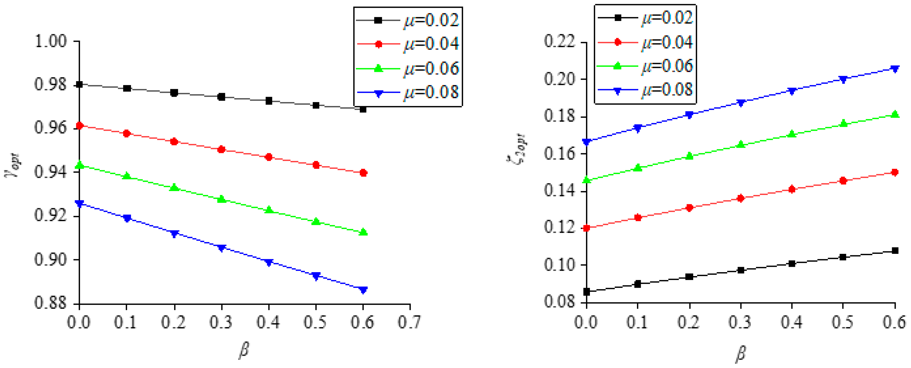
3.1. Parameter Optimization Analysis

As shown in Figure 7, the optimal frequency ratio γ o p t linearly decreases and the optimal damping ratio ζ 2 o p t linearly increases as the apparent mass ratio β increases, which is similar to the effect of μ on these two parameters.
As shown in Figure 8, with the increase in apparent mass ratio, the dynamic amplification factor of the transmission line gradually decreases, which means the vibration control performance of the TMDI keeps improving. When β = 0.6, the dynamic amplification factor of wire decreases by about 30% compared with conventional TMD. In addition, the increase in β also has a positive effect on the frequency bandwidth of the vibration control of the transmission line, as shown in Figure 8. Therefore, TMDI is superior to TMD in vibration control of transmission lines.

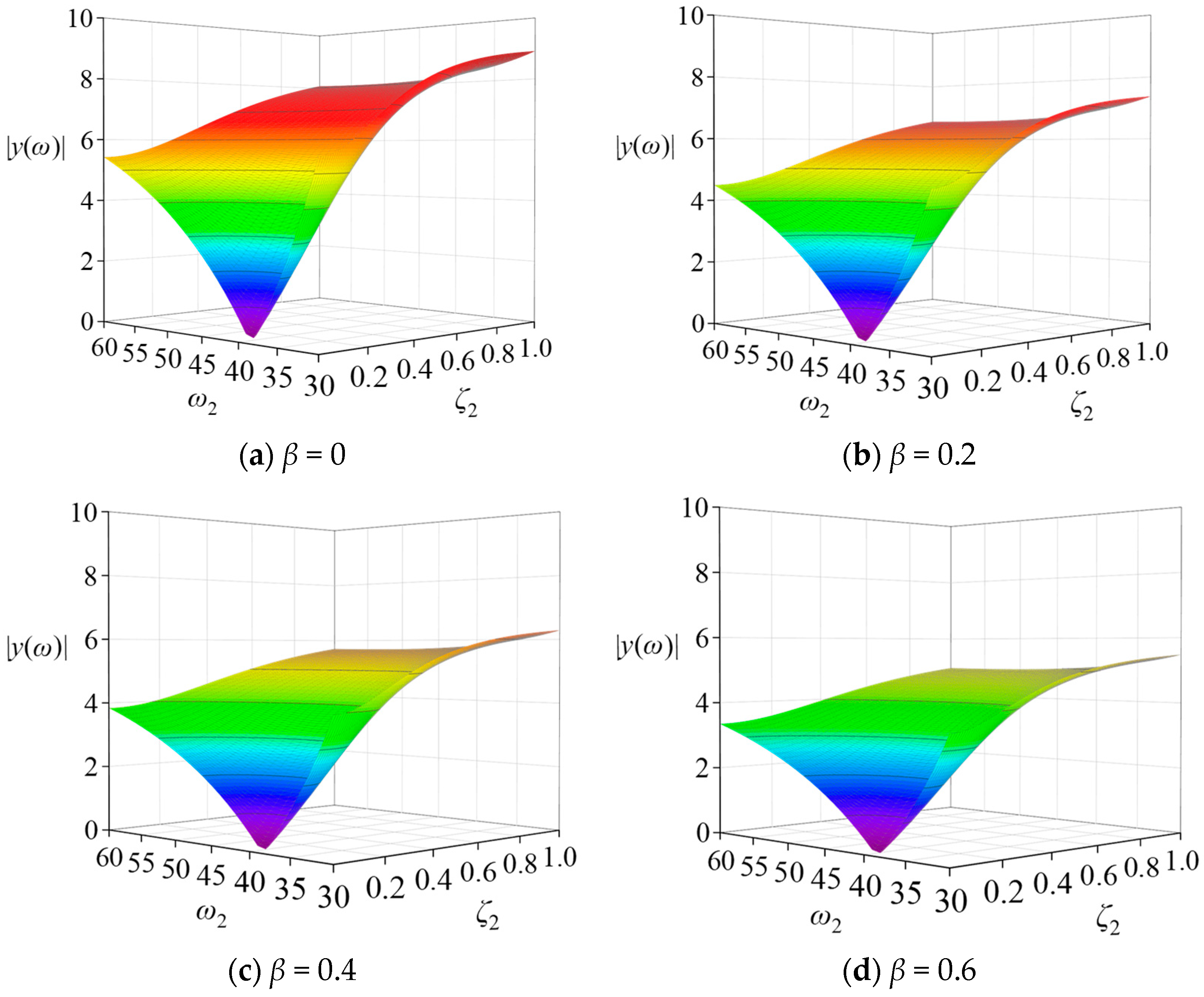
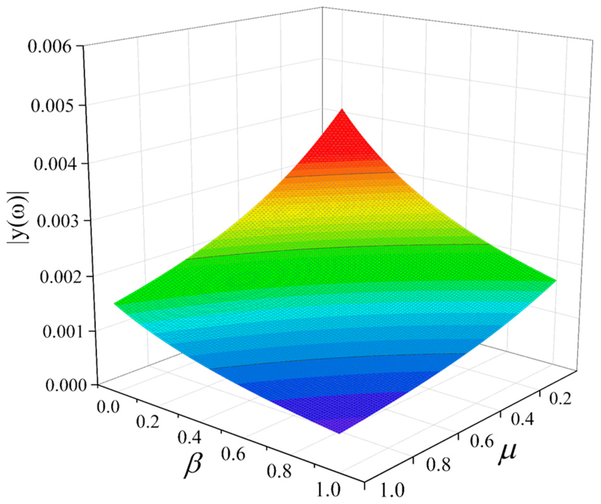
3.2. Parameters Sensitivity Analysis

To analyze the sensitivity of the parameters, the influence of the TMDI frequency ratio and damping ratio on the displacement response spectrum is discussed in this section.
As shown in Figure 9a, when μ = 0.02 and β = 0 (TMD), the peak displacement response spectrum of the transmission conductor-TMDI system is significantly affected by the tuning of the frequency ratio and the damping ratio. That is, for the conventional TMD with a mass ratio of 0.02, the tuning of damping ratio and frequency ratio have a large impact on its control performance, and the robustness of control performance is not ideal. As β increases, the effect of tuning the damping ratio and frequency ratio of DVA on the peak of the displacement response spectrum gradually decreases. It can be seen that the existence of the inerter plays a positive role in the robustness of the vibration control performance of DVA.
Next, the effect of mass ratio on the robustness of TMDI is discussed. As the mass ratio increases from 0.02 to 0.04, the peak displacement response spectrum of the transmission line-TMDI system is further reduced by the frequency ratio and damping ratio tuning of TMDI. That is, the mass ratio also has a positive effect on the robustness of TMDI vibration control.
In addition, it can be seen from Figure 9 and Figure 10 that the value of TMDI design frequency has a significant impact on the peak value of line response. But the damping ratio has limited influence on the vibration suppression effect.

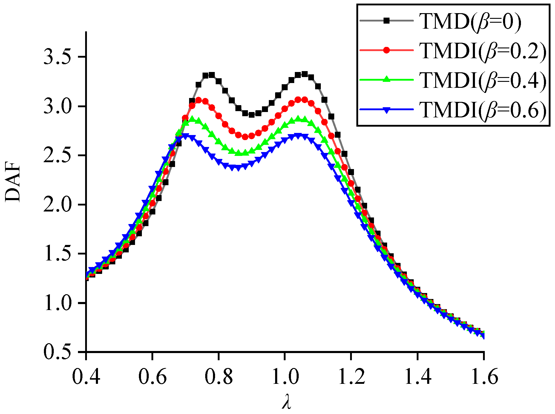
3.3. Vibration Control Performance of TMDI

To evaluate the vibration control performance of TMDI, the influence of the peak value of the transmission line displacement response spectrum on mass ratios and apparent mass ratios is discussed in this section.
As shown in Figure 11, with the decrease in mass ratio and apparent mass ratio, the peak value of the transmission line displacement response spectrum increases nonlinearly. Especially when the apparent mass ratio is between 0–0.2 and the mass ratio is between 0–0.4, the peak variation trend of this displacement spectrum is obvious. When β > 0.2 or μ > 0.4, the peak value of the displacement response spectrum tends to be stable gradually.
This means that in the process of TMDI optimization design, blindly increasing the mass ratio or apparent mass ratio has a limited effect on improving the vibration control performance of the TMDI.
To intuitively compare the vibration control performance of TMD and TMDI, the displacement response spectrums of transmission lines controlled by TMD or TMDI, respectively, are shown in Figure 12.
It can be seen from Figure 12 that the peaks of the transmission displacement response spectrum with TMDI and TMD are 1.34 and 1.58, respectively. Compared with conventional TMD, the peak value of the displacement spectrum of the transmission line with TMDI decreases by about 15%, and the vibration control performance is more significant.

4. Conclusions

In this paper, the differential motion equation of a transmission line with TMDI under harmonic excitation is established. Based on the Fourier transform, the displacement response of transmission lines with and without control is analyzed in the frequency domain. Based on fixed-point theory, the parameter optimization analysis of TMDI is carried out. According to the optimization results, by comparing with the conventional TMD, the vibration control performance of TMDI is evaluated. The conclusions are as follows:
(1)
With the increase in apparent mass ratio, β, the vibration control performance of TMDI increases. When β = 0.6, the dynamic amplification factor of the transmission line can be reduced by 30% compared with conventional TMD. In addition, the increase in β has a positive impact on the frequency band width of TMDIs vibration suppression;
(2)
The vibration control performance of TMDI is greatly affected by the frequency ratio, but the effect of the damping ratio is limited;
(3)
Both mass ratio and apparent mass ratio, especially β < 0.2 or μ < 0.4, have positive effects on the vibration control performance of TMDI. However, with the increase in mass ratio and apparent mass ratio, of which, the influence on the vibration control performance of TMDI gradually decreases;
(4)
When the mass ratio μ = 0.02, the peak value of the transmission displacement response spectrum is about 1.34. Compared with TMD, the peak value of the response spectrum decreases by about 12%, and TMDI has better vibration reduction performance than TMD.

Author Contributions

Conceptualization, Y.Z. and Y.S.; methodology, Y.Y.; software, L.Z.; data curation, C.W. and S.L.; writing—original draft preparation, Y.Y.; writing—review and editing, X.L. All authors have read and agreed to the published version of the manuscript.

Funding

The work described in this paper was supported by National Natural Science Foundation of China (Grant No. 52008070, 51778097, 51808088).

Conflicts of Interest

The authors declare no conflict of interest.

References

  1. Williamson, C.; Govardhan, R. A brief review of recent results in vortex-induced vibrations. J. Wind Eng. Ind. Aerodyn. 2008, 96, 713–735. [Google Scholar] [CrossRef]
  2. Andika, M.G.; Purabaya, W. Suppression of Resonance Induced Vibration Because of Wind Load at Bridge Structure by Using Passive Damper. Int. J. Technol. Eng. Stud. 2018, 4, 112–119. [Google Scholar]
  3. Guo, K.; Yang, Q.; Liu, M.; Li, B. Aerodynamic Damping Model for Vortex-induced Vibration of Suspended Circular Cylinder in Uniform Flow. J. Wind Eng. Ind. Aerodyn. 2021, 209, 104497. [Google Scholar] [CrossRef]
  4. Han, Y.; Zhou, X.; Wang, L.; Cai, C.S.; Yan, H.; Hu, P. Experimental investigation of the vortex-induced vibration of tapered light poles. J. Wind Eng. Ind. Aerodyn. 2021, 211, 104555. [Google Scholar] [CrossRef]
  5. Griffin, O.M. Some Recent Studies of Vortex Shedding With Application to Marine Tubulars and Risers. J. Energy Resour. Technol. 1982, 104, 2–13. [Google Scholar] [CrossRef]
  6. Khalak, A.; Williamson, C. Motions, Forces and Mode Transitions in Vortex-Induced Vibrations at Low Mass-Damping. J. Fluids Struct. 1999, 13, 813–851. [Google Scholar] [CrossRef]
  7. Blackburn, H.M.; Govardhan, R.N.; Williamson, C. Erratum: A complementary numerical and physical investigation of vortex-induced vibration. J. Fluids Struct. 2001, 15, 481–488. [Google Scholar] [CrossRef] [Green Version]
  8. Sarpkaya, T. A critical review of the intrinsic nature of vortex-induced vibrations. J. Fluids Struct. 2004, 19, 389–447. [Google Scholar] [CrossRef]
  9. Gabbai, R.D.; Benaroya, H. An overview of modeling and experiments of vortex-induced vibration of circular cylinders. J. Sound Vib. 2005, 282, 575–616. [Google Scholar] [CrossRef]
  10. Sumner, D. Two circular cylinders in cross-flow: A review. J. Fluids Struct. 2010, 26, 849–899. [Google Scholar] [CrossRef]
  11. Wu, X.; Fei, G.; Hong, Y. A review of recent studies on vortex-induced vibrations of long slender cylinders. J. Fluids Struct. 2012, 28, 292–308. [Google Scholar] [CrossRef] [Green Version]
  12. Mackowski, A.; Williamson, C. An experimental investigation of vortex-induced vibration with nonlinear restoring forces. Phys. Fluids 2013, 25, 087101. [Google Scholar] [CrossRef]
  13. Huynh, B.H.; Tjahjowidodo, T.; Zhong, Z.W.; Wang, Y.; Srikanth, N. Design and experiment of controlled bistable vortex induced vibration energy harvesting systems operating in chaotic regions. Mech. Syst. Signal Process. 2018, 98, 1097–1115. [Google Scholar] [CrossRef]
  14. Huang, X.; Yang, B. Investigation on the energy trapping and conversion performances of a multi-stable vibration absorber. Mech. Syst. Signal Process. 2021, 160, 107938. [Google Scholar] [CrossRef]
  15. Wang, E.; Xu, W.; Gao, X.; Liu, L.; Xiao, Q.; Ramesh, K. The effect of cubic stiffness nonlinearity on the vortex-induced vibration of a circular cylinder at low Reynolds numbers. Ocean. Eng. 2018, 173, 12–27. [Google Scholar] [CrossRef] [Green Version]
  16. Zhang, M.; Song, Y.; Abdelkefi, A.; Yu, H.; Wang, J. Vortex-Induced Vibration of a Circular Cylinder with Nonlinear Stiffness: Prediction Using Forced Vibration Data. Nonlinear Dyn. 2022. [Google Scholar] [CrossRef]
  17. Soto, M.G.; Adeli, H. Tuned Mass Dampers. Arch. Comput. Methods Eng. 2013, 20, 419–431. [Google Scholar] [CrossRef]
  18. Bitaraf, M.; Hurlebaus, S.; Barroso, L.R. Active and Semi-active Adaptive Control for Undamaged and Damaged Building Structures Under Seismic Load. Comput. -Aided Civ. Infrastruct. Eng. 2011, 27, 48–64. [Google Scholar] [CrossRef]
  19. Lei, Y.; Wu, D.T.; Lin, Y. A Decentralized Control Algorithm for Large-Scale Building Structures. Comput. Aided Civ. Infrastruct. Eng. 2012, 27, 2–13. [Google Scholar] [CrossRef]
  20. Nigdeli, S.M.; Boduroglu, M.H. Active Tendon Control of Torsionally Irregular Structures under Near-Fault Ground Motion Excitation. Comput. -Aided Civ. Infrastruct. Eng. 2013, 28, 718–736. [Google Scholar] [CrossRef]
  21. Hermann, F. Device for Damper Vibration of Bodies. 1909. Available online: https://patentimages.storage.googleapis.com/ac/69/ab/4191d1f88063d0/US989958.pdf (accessed on 28 March 2022).
  22. Laura, P.A.A. Discussion: Performance of Multiple Mass Dampers under Random Loading. J. Struct. Eng. 1996, 122, 981–982. [Google Scholar] [CrossRef]
  23. Lin, J.L.; Tsai, K.C.; Yu, Y.J. Bi-directional coupled tuned mass dampers for the seismic response control of two-way asymmetric-plan buildings. Earthq. Eng. Struct. Dyn. 2011, 40, 675–690. [Google Scholar] [CrossRef]
  24. Huang, M.F.; Tse, K.T.; Chan, C.M.; Lou, W. Integrated Structural Optimization and Vibration Control for Improving Wind-Induced Dynamic Performance of Tall Buildings. Int. J. Struct. Stab. Dyn. 2011, 11, 1139–1161. [Google Scholar] [CrossRef]
  25. Patil, V.B.; Jangid, R.S. Optimum Multiple Tuned Mass Dampers for the Wind Excited Benchmark Building. Statyba 2011, 17, 540–557. [Google Scholar]
  26. Nagase, T. Earthquake records observed in tall buildings with tuned pendulum mass damper. In Proceedings of the 12th World Conference on Earthquake Engineering, Auckland, New Zealand, 30 January–4 February 2000. [Google Scholar]
  27. Gerges, R.R.; Vickery, B.J. Optimum design of pendulum-type tuned mass dampers. Struct. Des. Tall Spec. Build. 2005, 14, 353–368. [Google Scholar] [CrossRef]
  28. Almazán, J.L.; Juan, C.; Inaudi, J.A.; López-García, D.; Izquierdo, L.E. A bidirectional and homogeneous tuned mass damper: A new device for passive control of vibrations. Eng. Struct. 2007, 29, 1548–1560. [Google Scholar] [CrossRef]
  29. Zhang, M.; Xu, F. Tuned mass damper for self-excited vibration control: Optimization involving nonlinear aeroelastic effect. J. Wind Eng. Ind. Aerodyn. 2022, 220, 104836. [Google Scholar] [CrossRef]
  30. Wang, Z.; Li, H.N.; Song, G. Aeolian vibration control of Power Transmission line Using Stockbridge Type Dampers—A review. Int. J. Struct. Stab. Dyn. 2021, 21, 2130001. [Google Scholar] [CrossRef]
  31. Stockbridge, G.H. Vibration Damper. U.S. Patent 1,675,391, 3 July 1928. [Google Scholar]
  32. Claren, R.; Diana, G. Mathematical analysis of transmission line vibration. IEEE Trans. Power Appar. Syst. 1969, 12, 1741–1771. [Google Scholar] [CrossRef]
  33. Wagner, H.; Ramamurti, V.; Sastry RV, R.; Hartmann, K. Dynamics of Stockbridge dampers. J. Sound Vib. 1973, 30, 207–220, IN1–IN2. [Google Scholar] [CrossRef]
  34. Leblond, A.; Hardy, C. On the estimation of a 2 × 2 complex stiffness matrix of symmetric stockbridge-type dampers. In Proceedings of the 3rd International Symposium on Cable Dynamics, Trondheim, Norway, 16–18 August 1999. [Google Scholar]
  35. Luo, X.; Wang, L.; Zhang, Y. Nonlinear numerical model with contact for Stock-bridge vibration damper and experimental validation. J. Vib. Control. 2016, 22, 1217–1227. [Google Scholar] [CrossRef]
  36. Vaja, N.K.; Barry, O.; DeJong, B. Finite element modeling of Stockbridge damper and vibration analysis: Equivalent cable stiffness. In Proceedings of the International Design Engineering Technical Conferences and Computers and Information in Engineering Conference, Cleveland, OH, USA, 6–9 August 2017. [Google Scholar] [CrossRef] [Green Version]
  37. Richardson, A.S. Vibration damping required for overhead lines. IEEE Trans. Power Deliv. 1995, 10, 934–940. [Google Scholar] [CrossRef]
  38. Vecchiarelli, J.; Currie, I.G.; Havard, D.G. Computational analysis of aeolian conductor vibration with a stockbridge type damper. J. Fluids Struct. 2000, 14, 489–509. [Google Scholar] [CrossRef]
  39. Zhang, B.; Gong, W.S.; Wang, Z.H.; Zhang, M.G.; Han, L.; Zhang, Y. Study on equivalent viscous damping of aeolian vibration for transmission line by AACSR-400 steel core alminum alloy wire. Key Eng. Mater. 2017, 723, 94–99. [Google Scholar] [CrossRef]
  40. Smith, M.C. Synthesis of mechanical networks: The inerter. IEEE Trans. Autom. Control 2002, 47, 1648–1662. [Google Scholar] [CrossRef] [Green Version]
  41. Arakaki, T.; Kuroda, H.; Arima, F.; Inoue, Y.; Baba, K. Development of seismic devices applied to ball screw: Part 1 Basic performance test of RD-series. J. Technol. Des. 1999, 5, 239–244. (In Japanese) [Google Scholar]
  42. Arakaki, T.; Kuroda, H.; Arima, F.; Inoue, Y.; Baba, K. Development of seismic devices applied to ball screw: Part 2 Performance test and evaluation of RD-series. J. Technol. Des. 1999, 5, 265–270. (In Japanese) [Google Scholar]
  43. Soong, T. State-of-the-art review: Active structural control in civil engineering. Eng. Struct. 1988, 10, 74–84. [Google Scholar] [CrossRef]
  44. Ma, R.; Bi, K.; Hao, H. Inerter-based structural vibration control: A state-of-the-art review. Eng. Struct. 2021, 243, 112655. [Google Scholar] [CrossRef]
  45. Marian, L.; Giaralis, A. Optimal design of a novel tuned mass-damper–inerter (TMDI) passive vibration control configuration for stochastically support-excited structural systems. Probabilistic Eng. Mech. 2014, 38, 156–164. [Google Scholar] [CrossRef]
  46. Tiwari, N.D.; Gogoi, A.; Hazra, B.; Wang, Q. A shape memory alloy-tuned mass damper inerter system for passive control of linked-SDOF structural systems under seismic excitation. J. Sound Vib. 2021, 494, 115893. [Google Scholar] [CrossRef]
  47. Ruiz, R.; Taflanidis, A.A.; Giaralis, A.; Lopez-Garcia, D. Risk-informed optimization of the tuned mass-damper-inerter (TMDI) for the seismic protection of multi-story building structures. Eng. Struct. 2018, 177, 836–850. [Google Scholar] [CrossRef]
  48. Giaralis, A.; Taflanidis, A.A. Optimal tuned mass-damper-inerter (TMDI) design for seismically excited MDOF structures with model uncertainties based on reliability criteria. Struct. Control Health Monit. 2018, 25, e2082. [Google Scholar] [CrossRef]
  49. Pietrosanti, D.; De Angelis, M.; Basili, M. A generalized 2-DOF model for optimal design of MDOF structures controlled byTuned Mass Damper Inerter (TMDI). Int. J. Mech. Sci. 2020, 185, 105849. [Google Scholar] [CrossRef]
  50. Taflanidis, A.A.; Giaralis, A.; Patsialis, D. Multi-objective optimal design of inerter-based vibration absorbers for earthquake protection of multi-storey building structures. J. Frankl. Inst. 2019, 356, 7754–7784. [Google Scholar] [CrossRef]
  51. Giaralis, A.; Petrini, F. Wind-Induced Vibration Mitigation in Tall Buildings Using the Tuned Mass-Damper-Inerter. J. Struct. Eng. 2017, 143, 04017127. [Google Scholar] [CrossRef]
  52. Petrini, F.; Giaralis, A.; Wang, Z. Optimal tuned mass-damper-inerter (TMDI) design in wind-excited tall buildings for occupants’ comfort serviceability performance and energy harvesting. Eng. Struct. 2020, 204, 109904. [Google Scholar] [CrossRef]
  53. Xu, K.; Bi, K.; Han, Q.; Li, X.; Du, X. Using tuned mass damper inerter to mitigate vortex-induced vibration of long-span bridges: Analytical study. Eng. Struct. 2019, 182, 101–111. [Google Scholar] [CrossRef]
  54. Dai, J.; Xu, Z.D.; Gai, P.P. Tuned mass-damper-inerter control of wind-induced vibration of flexible structures based on inerter location. Eng. Struct. 2019, 199, 109585.1–109585.15. [Google Scholar] [CrossRef]
  55. Dai, J.; Xu, Z.; Gai, P.; Hu, Z. Optimal design of tuned mass damper inerter with a Maxwell element for mitigating the vortex-induced vibration in bridges. Mech. Syst. Signal. Process. 2021, 148, 107180. [Google Scholar] [CrossRef]
  56. Zhang, Z.; Fitzgerald, B. Tuned mass damper inerter (TMDI) for suppressing edgewise vibrations of wind turbine blades. Eng. Struct. 2020, 221, 110928. [Google Scholar] [CrossRef]
  57. Den Hartog, J.P. Mechanical Vibrations; Courier Corporation: North Chelmsford, MA, USA, 1985. [Google Scholar]
  58. Zhou, S.; Jean-Mistral, C.; Chesne, S. Influence of inerters on the vibration control effect of series double tuned mass dampers: Two layouts and analytical study. Struct. Control Health Monit. 2019, 26, e2414. [Google Scholar] [CrossRef]
  59. Wang, Z.; Giaralis, A. Enhanced motion control performance of the tuned mass damper inerter (TMDI) through primary structure shaping. Struct. Control. Health Monit. 2021, 28, e2756. [Google Scholar] [CrossRef]
  60. Kaveh, A.; Mahdavi, V.R. Colliding Bodies Optimization: A Novel Meta-Heuristic Method; Elsevier Ltd.: Amsterdam, The Netherlands, 2014. [Google Scholar]
  61. Kaveh, A.; Fahimi Farzam, M.; Hojat Jalali, H.; Maroofiazar, R. Robust optimum design of a tuned mass damper inerter. Acta Mech. 2020, 231, 3871–3896. [Google Scholar] [CrossRef]
  62. Li, J.; Zhang, H.; Chen, S.; Zhu, D. Optimization and sensitivity of TMD parameters for mitigating bridge maximum vibration response under moving forces—ScienceDirect. Structures 2020, 28, 512–520. [Google Scholar] [CrossRef]
Figure 1. Schematic of Karman Vortex Street.
Buildings 12 00435 g001
Figure 2. Schematic drawing of the Stockbridge damper.
Buildings 12 00435 g002
Figure 3. Schematic drawing of inerter element.
Buildings 12 00435 g003
Figure 4. Schematic drawing of a TMDI.
Buildings 12 00435 g004
Figure 5. Transmission line element diagram.
Buildings 12 00435 g005
Figure 6. Transmission line—TMDI system model.
Buildings 12 00435 g006
Figure 7. Optimal design parameters for ground TMDI.
Buildings 12 00435 g007
Figure 8. Frequency response curve comparison.
Buildings 12 00435 g008
Figure 9. Variation of the maximum displacement in the span, μ = 0.02.
Buildings 12 00435 g009
Figure 10. Variation of the maximum displacement in the span, μ = 0.04.
Buildings 12 00435 g010
Figure 11. The influence of mass ratios and apparent mass ratios on the peak value of displacement response spectrums.
Buildings 12 00435 g011
Figure 12. The displacement response spectrums of transmission line with TMD and TMDI (μ = 0.02).
Buildings 12 00435 g012
Table 1. Transmission wire parameter table.
ParametersNumerical
Value
ParametersNumerical
Value
Structure
Number of shares/diameter
(mm)
Aluminum48/2.85Outer diameter (mm)23.76
Steel7/2.22Calculation of
pull-off force (N)
83,410
Calculated areaAluminum306.21Modulus of elasticity (N/mm2)65,000
Steel27.1Mass per unit length (kg/km)1058
Total333.31Length of test
section (m)
30.84
Publisher’s Note: MDPI stays neutral with regard to jurisdictional claims in published maps and institutional affiliations.

