Influence of Equipment Operation Parameters on the Characteristics of a Track Produced with Construction 3D Printing
Abstract
:1. Introduction
- -
- Constructive–structural, which determines the spatial scheme of printed elements and structures, represented as a digital model;
- -
- Robotic, which includes control systems, movement, and the positioning of the molding device;
- -
- Formular–technological, which includes the compositions of building mixtures, equipment, operations, and regimes for their preparation, molding, and providing conditions to achieve design properties.
2. Materials and Methods
2.1. Materials
2.2. Experimental Setup and Equipment
2.3. Methods
- -
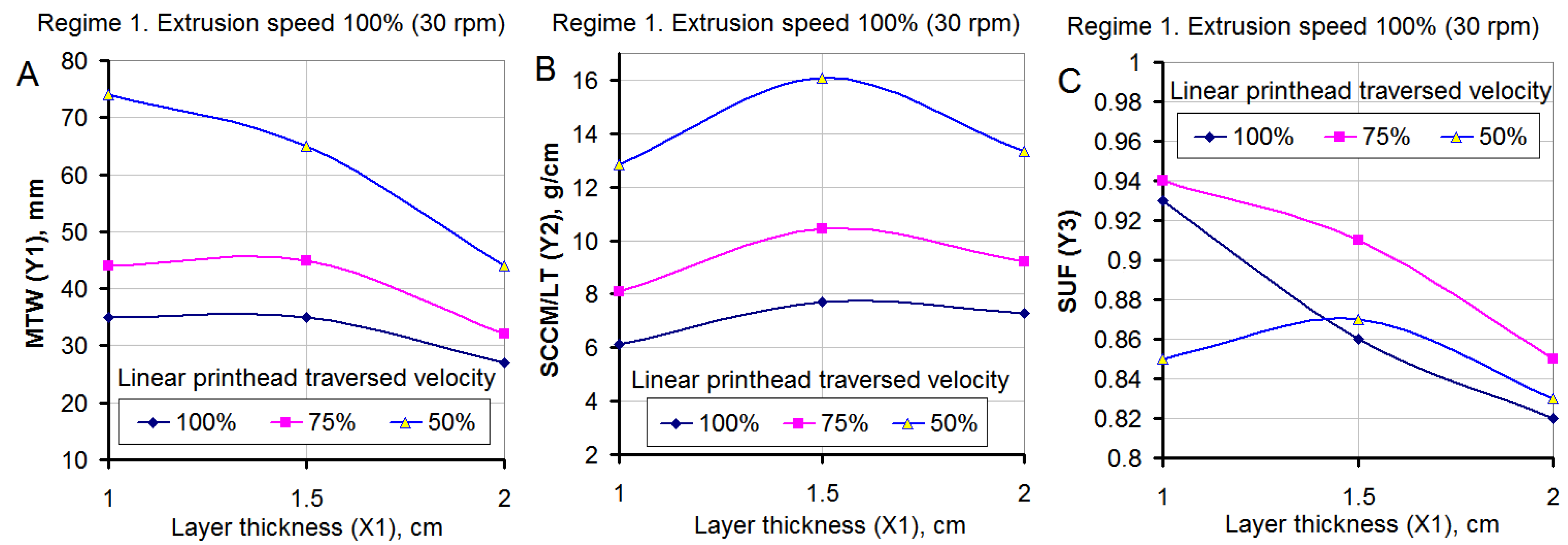
- Regime 1: constant speed of rotation of the screw, with the linear printhead traversed velocity of the forming device varying at three levels;
- -
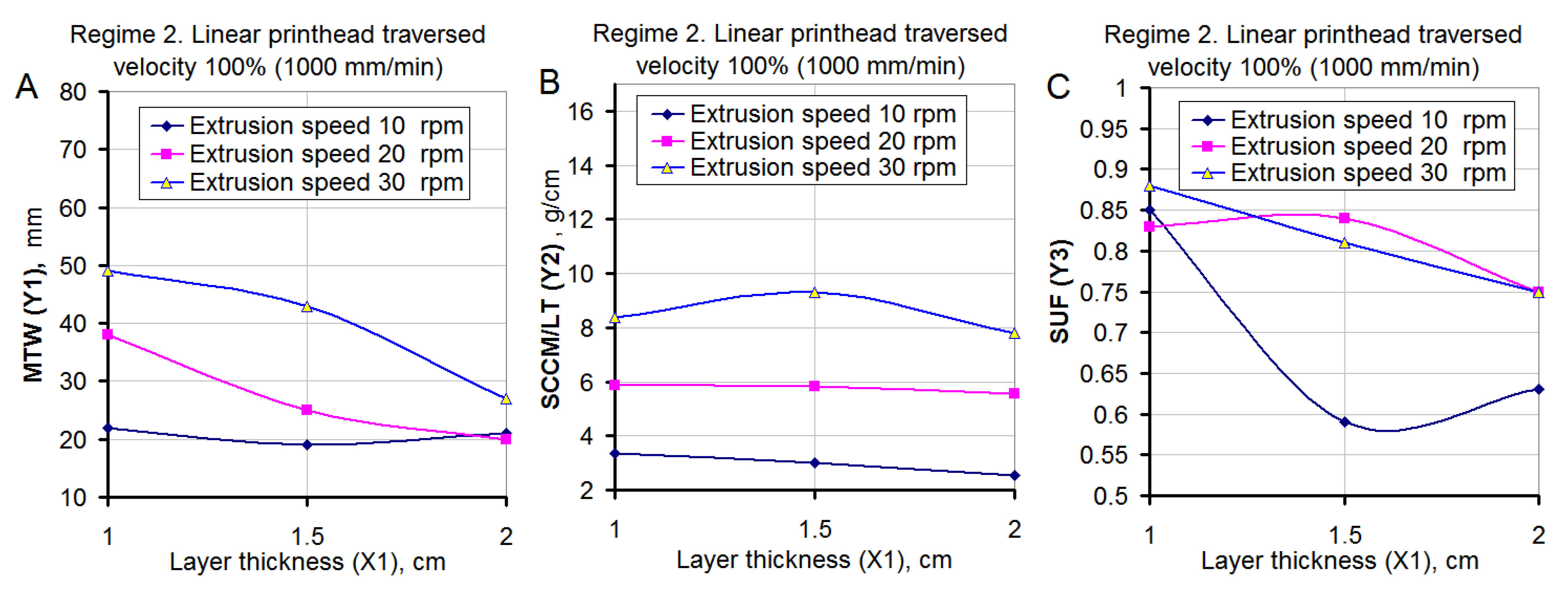
- Regime 2: constant linear printhead traversed velocity of the forming device with the rotation speed of the screw varying at three levels.
- -
- Layer height (X1) is the height of the printed layer (cm), which ranged from 1 to 2 cm in the article. Increasing the layer height leads to an increase in the height of the final structure and reduces the number of horizontal seams that weaken the structure. However, when printing a structure with a varying cross-section, when the longitudinal axes of the layers are displaced relative to each other, and a large layer thickness can lead to a loss of stability of the freshly printed structure;
- -
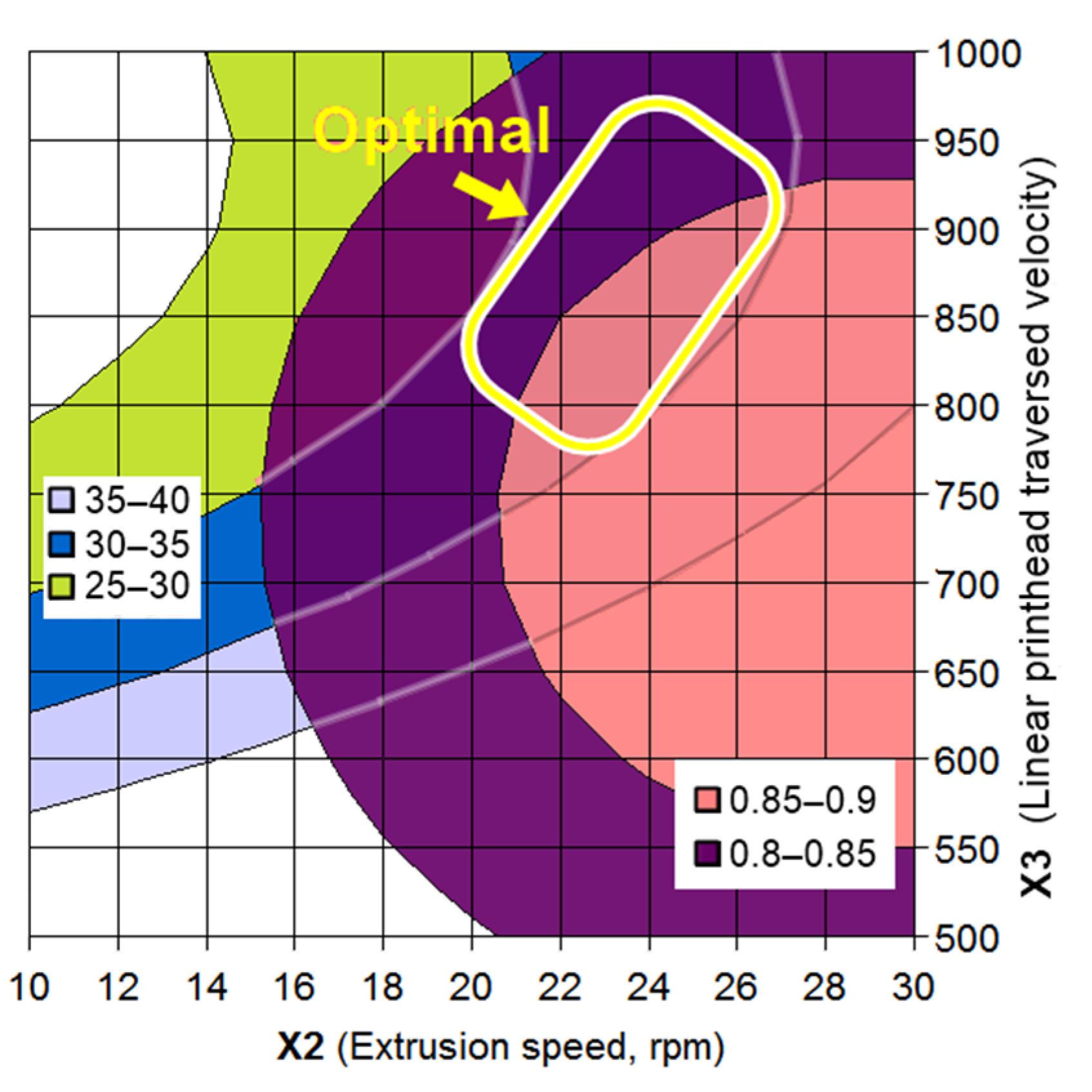
- Extrusion speed (X2) is the rotation speed of the extruder screw, which ranged from 10 to 30 rpm in the article. This parameter largely determines the amount of mixture output and the width of the printed track;
- -
- Linear printhead traversed velocity (X3) is the speed at which the extruder nozzle moves during printing, which ranged from 500 to 1000 mm/min in the article. Increasing this parameter contributes to an increase in the overall speed of the structure formation, reduces the effect of printer structure vibrations on the straightness of the track.
- -
- Y1 is the maximum track width (MTW), in mm. It is determined by the top layer, during the printing process in which there is no influence of the glass substrate. This parameter is the most visually significant in assessing the stability of the printing process. At the same time, printing a track with a variable width can be used as a way to increase the aesthetic expressiveness of the design. There is no consensus on the best track width in relation to nozzle diameter. Within the framework of this article, the range of 25-40 mm was identified as optimal;
- -
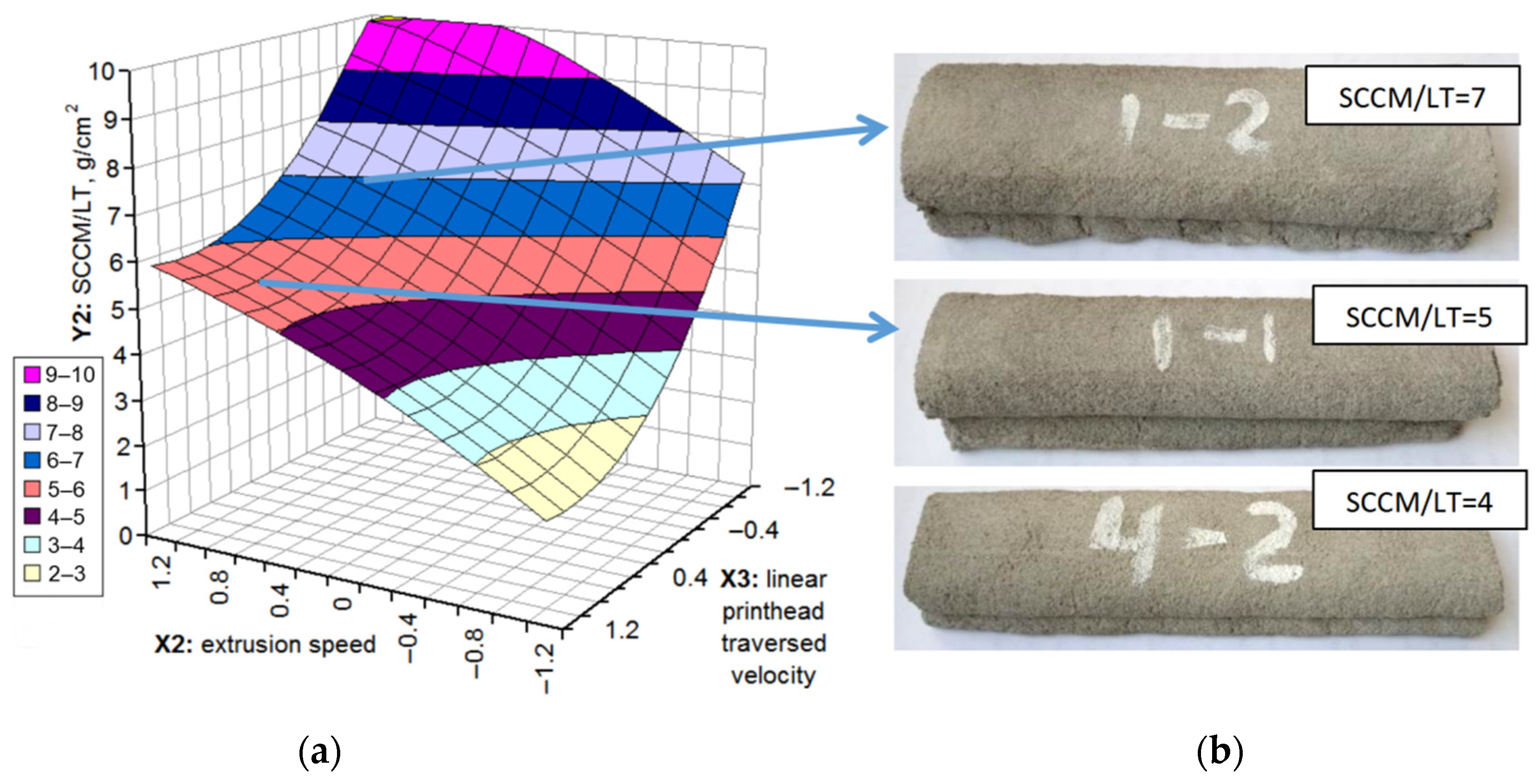
- Y2 is specific consumption of the “concrete mixture/layer thickness” ratio (SCCM/LT), in g/cm2. It represents the ratio of the specific consumption of the mixture for printing a track related to the layer thickness. A specific case of construction 3D printing should correspond to its own range of optimal values of this property, which makes it extremely difficult to compare the values obtained by different researchers. In this case, the optimal variation range was 4–7 g/cm2;
- -
- Y3 is the section utilization factor (SUF). This is a dimensionless parameter. It is calculated as a “working section area of the layer/sectional area of the layer” ratio (WSAL/SAL) and characterizes the part of the mixture in the track involved in receiving and transmitting loads. Considering this parameter, it is recommended to focus on the maximum approximation of its values to 1. This corresponds to a strictly rectangular cross-sectional shape of the track and a smooth outer surface of the structures. In practice, the specified value when using a round nozzle is unattainable; therefore, within the framework of the study, coefficient values of 0.8, at least, were recognized as acceptable.
- -
- Contact area width (CAW), in mm. This parameter is used to calculate other parameters;
- -
- Specific consumption of the concrete mix (SCCM), in g/cm. This parameter is calculated as the ratio of the mass of the sample to the product of its length and the number of layers;
- -
- Working section area of the layer (WSAL), in cm2. This parameter is calculated as the product of the width of the contact zone of the layers and the height of the layer;
- -
- Sectional area of the layer (SAL), in cm2. The track cross-sectional area is approximately determined as the area of an ellipse with a small diameter equal to the layer height, and a large diameter equal to the maximum track width (Y1);
- -
- Visual assessment of results (VAR). This is evaluated in points from 0 to 5 and characterizes the overall aesthetics of the sample. This assessment is not completely objective and is intended only to show the priorities and preferences of the authors of the article.
3. Results
- -
- for layer width:
- -
- for the specific consumption of the mixture per layer related to its thickness:
- -
- for the section utilization factor:
4. Discussion
5. Conclusions
Author Contributions
Funding
Institutional Review Board Statement
Informed Consent Statement
Data Availability Statement
Acknowledgments
Conflicts of Interest
References
- Praveena, B.A.; Lokesh, N.; Buradi, A.; Santhosh, N.; Praveena, B.L.; Vignesh, R. A comprehensive review of emerging additive manufacturing (3D printing technology): Methods, materials, applications, challenges, trends and future potential. Mater. Today Proc. 2021, 52, 1309–1313. [Google Scholar] [CrossRef]
- Mechtcherine, V.; Bos, F.P.; Perrot, A.; Leal da Silva, W.R.; Nerella, V.N.; Fataei, S.; Wolfs, R.J.M.; Sonebi, M.; Roussel, N. Extrusion-based additive manufacturing with cement-based materials—Production steps, processes, and their underlying physics: A review. Cem. Concr. Res. 2020, 132, 106037. [Google Scholar] [CrossRef]
- Jardini, A.L.; Larosa, M.A.; Kaasi, A.; Kharmandayan, P. Additive Manufacturing in Medicine. Encycl. Smart Mater. 2017, 1, 300–320. [Google Scholar] [CrossRef]
- Brünler, R.; Aibibu, D.; Wöltje, M.; Anthofer, A.-M.; Cherif, C. In silico modeling of structural and porosity properties of additive manufactured implants for regenerative medicine. Mater. Sci. Eng. C 2017, 76, 810–817. [Google Scholar] [CrossRef]
- Cheng, D.; Wei, C.; Huang, Y.; Zhang, Z.; Wang, D.; Liu, Z.; Newman, M.; Ma, T.; Chueh, Y.-H.; Zhang, X.; et al. Additive manufacturing of lithium aluminosilicate glass-ceramic/metal 3D electronic components via multiple material laser powder bed fusion. Addit. Manuf. 2021, 49, 102481. [Google Scholar] [CrossRef]
- Jiang, D.; Al Shraida, H.A.; Ning, F. Non-planar polymer-based flexible electronics fabricated by a four-axis additive manufacturing process. Mater. Lett. 2021, 294, 129748. [Google Scholar] [CrossRef]
- Mohanavel, V.; Ashraff Ali, K.S.; Ranganathan, K.; Allen Jeffrey, J.; Ravikumar, M.M.; Rajkumar, S. The roles and applications of additive manufacturing in the aerospace and automobile sector. Mater. Today Proc. 2021, 47, 405–409. [Google Scholar] [CrossRef]
- Jones, R.; Singh Raman, R.K.; Iliopoulos, A.P.; Michopoulos, J.G.; Phan, N.; Peng, D. Additively manufactured Ti-6Al-4V replacement parts for military aircraft. Int. J. Fatigue 2019, 124, 227–235. [Google Scholar] [CrossRef]
- Romero, P.E.; Arribas-Barrios, J.; Rodriguez-Alabanda, O.; González-Merino, R.; Guerrero-Vaca, G. Manufacture of polyurethane foam parts for automotive industry using FDM 3D printed molds. CIRP J. Manuf. Sci. Technol. 2021, 32, 396–404. [Google Scholar] [CrossRef]
- Matta, A.K.; Kodali, S.P.; Ivvala, J.; Kumar, P.J. Metal Prototyping the future of Automobile Industry: A review. Mater. Today Proc. 2018, 5, 17597–17601. [Google Scholar] [CrossRef]
- Singh, G.; Missiaen, J.-M.; Bouvard, D.; Chaix, J.-M. Additive manufacturing of 17–4 PH steel using metal injection molding feedstock: Analysis of 3D extrusion printing, debinding and sintering. Addit. Manuf. 2021, 47, 102287. [Google Scholar] [CrossRef]
- Lee, J.-H.; Lee, C.-M.; Kim, D.-H. Repair of damaged parts using wire arc additive manufacturing in machine tools. J. Mater. Res. Technol. 2021, 16, 13–24. [Google Scholar] [CrossRef]
- Kim, D.H.; Yoon, G.H. Active acoustic absorption device using additive manufacturing technique for normal incident wave. Appl. Acoust. 2021, 178, 108006. [Google Scholar] [CrossRef]
- Paolini, A.; Kollmannsberger, S.; Rank, E. Additive manufacturing in construction: A review on processes, applications, and digital planning methods. Addit. Manuf. 2019, 30, 100894. [Google Scholar] [CrossRef]
- Van Der Putten, J.; Rahul, A.V.; De Schutter, G.; Van Tittelboom, K. Development of 3D Printable Cementitious Composites with the Incorporation of Polypropylene Fibers. Materials 2021, 14, 4474. [Google Scholar] [CrossRef]
- Labonnote, N.; Rønnquist, A.; Manum, B.; Rüther, P. Additive construction: State-of-the-art, challenges and opportunities. Autom. Constr. 2016, 72, 347–366. [Google Scholar] [CrossRef]
- Tay, Y.W.D.; Panda, B.; Paul, S.C.; Mohamed, N.A.N.; Tan, M.J.; Leong, K.F. 3D printing trends in building and construction industry: A review. Virtual Phys. Prototyp. 2017, 3, 261–276. [Google Scholar] [CrossRef]
- Korniejenko, K.; Łach, M. Geopolymers reinforced by short and long fibres—Innovative materials for additive manufacturing. Curr. Opin. Chem. Eng. 2020, 28, 167–172. [Google Scholar] [CrossRef]
- Wickson, F.; Carew, A.L.; Russell, A.W. Transdisciplinary research: Characteristics, quandaries and quality. Futures 2006, 38, 1046–1059. [Google Scholar] [CrossRef]
- Lesovik, V.; Volodchenko, A.; Glagolev, E.; Lashina, I.; Fischer, H.B. Geonics (geomimetics) as a theoretical basis for new generation compositing. In Proceedings of the 14th International Congress for Applied Mineralogy (ICAM2019), Belgorod, Russia, 23–27 September 2019; pp. 344–347. [Google Scholar] [CrossRef] [Green Version]
- Loy, J.; Canning, S. Clash of Cultures: Fashion, Engineering, and 3D Printing. In Disruptive Technology: Concepts, Methodologies, Tools, and Applications; Information Resources Management Association, Ed.; IGI Global: Hershey, PA, USA, 2020; pp. 926–954. [Google Scholar] [CrossRef]
- Lesovik, V.S.; Glagolev, E.S.; Elistratkin, M.Y.; Pospelova, M.A.; Alfimova, N.I. The method of creating and measuring the printability of fine-grained concrete. Mater. Sci. Forum 2021, 1017, 71–80. [Google Scholar] [CrossRef]
- Lesovik, V.S.; Glagolev, E.S.; Elistratkin, M.Y.; Podgorniy, D.S. On the issue of measuring the strength of additively manufactured concrete. Lect. Notes Civ. Eng. 2021, 147, 104–110. [Google Scholar] [CrossRef]
- Elistratkin, M.Y.; Lesovik, V.S.; Alfimova, N.I.; Glagolev, E.S. About developing of the building press technologies. Bull. Belgorod State Technol. Univ. Named After. V. G. Shukhov 2018, 5, 11–19. [Google Scholar] [CrossRef]
- Souza, M.T.; Ferreira, I.M.; Guzi de Moraes, E.; Senff, L.; Novaes de Oliveira, A.P. 3D printed concrete for large-scale buildings: An overview of rheology, printing parameters, chemical admixtures, reinforcements, and economic and environmental prospects. J. Build. Eng. 2020, 32, 101833. [Google Scholar] [CrossRef]
- Tay, Y.W.D.; Li, M.Y.; Tan, M.J. Effect of printing parameters in 3D concrete printing: Printing region and support structures. J. Mater. Process. Technol. 2019, 271, 261–270. [Google Scholar] [CrossRef]
- Xiao, I.; Ji, G.; Zhang, Y.; Ma, G.; Mechtcherine, V.; Pan, J.; Wang, L.; Ding, T.; Duan, Z.; Du, S. Large-scale 3D printing concrete technology: Current status and future opportunities. Cem. Concr. Compos. 2021, 122, 104115. [Google Scholar] [CrossRef]
- Kruger, J.; Cho, S.; Zeranka, S.; Viljoen, C.; van Zijl, G. 3D concrete printer parameter optimisation for high rate digital construction avoiding plastic collapse. Compos. Part B Eng. 2020, 183, 107660. [Google Scholar] [CrossRef]
- Xiao, J.; Zou, S.; Yu, Y.; Wang, Y.; Ding, T.; Zhu, Y.; Yu, J.; Li, S.; Duan, Z.; Wu, Y.; et al. 3D recycled mortar printing: System development, process design, material properties and on-site printing. J. Build. Eng. 2020, 32, 101779. [Google Scholar] [CrossRef]
- Liu, Z.; Li, M.; Tay, Y.W.D.; Weng, Y.; Wong, T.N.; Tan, M.J. Rotation nozzle and numerical simulation of mass distribution at corners in 3D cementitious material printing. Addit. Manuf. 2020, 34, 101190. [Google Scholar] [CrossRef]
- Nerella, V.; Krause, M.; Nather, M.; Mechtcherine, V. Studying printability of fresh concrete for formwork free concrete on-site 3D printing technology (CONPrint3D). In Proceedings of the 25th Conference on Rheology of Building Materials, Regensburg, Germany, 2–3 March 2016. [Google Scholar]
- Le, T.T.; Austin, S.A.; Lim, S.; Buswell, R.A.; Gibb, A.G.F.; Thorpe, T. Mix design and fresh properties for high-performance printing concrete. Mater. Struct. 2012, 45, 1221–1232. [Google Scholar] [CrossRef] [Green Version]
- Khoshnevis, B. Automated construction by contour crafting- related robotics and information technologies. Autom. Constr. 2004, 13, 5–19. [Google Scholar] [CrossRef]



| No | Sample ID | Regime | Studied Factors (Variables) in Natural and Coded Form | Variation Levels of Studied Factors (Variables) | |||||||
|---|---|---|---|---|---|---|---|---|---|---|---|
| X1: Layer Height h, mm | X2: Extrusion Speed, rpm | X3: Linear Printhead Traversed Velocity, mm/min | X1 | X2 | X3 | X12 | X22 | X32 | |||
| 1 | 1-1 | 1 | 15 | 30 | 1000 | 0 | 1 | 1 | 0 | 1 | 1 |
| 2 | 1-2 | 15 | 30 | 750 | 0 | 1 | 0 | 0 | 1 | 0 | |
| 3 | 1-3 | 15 | 30 | 500 | 0 | 1 | −1 | 0 | 1 | 1 | |
| 4 | 2-1 | 2 | 15 | 10 | 1000 | 0 | −1 | 1 | 0 | 1 | 1 |
| 5 | 2-2 | 15 | 20 | 1000 | 0 | 0 | 1 | 0 | 0 | 1 | |
| 6 | 2-3 | 15 | 30 | 1000 | 0 | 1 | 1 | 0 | 1 | 1 | |
| 7 | 3-1 | 1 | 10 | 30 | 1000 | −1 | 1 | 1 | 1 | 1 | 1 |
| 8 | 3-2 | 10 | 30 | 750 | −1 | 1 | 0 | 1 | 1 | 0 | |
| 9 | 3-3 | 10 | 30 | 500 | −1 | 1 | −1 | 1 | 1 | 1 | |
| 10 | 4-1 | 2 | 10 | 10 | 1000 | −1 | −1 | 1 | 1 | 1 | 1 |
| 11 | 4-2 | 10 | 20 | 1000 | −1 | 0 | 1 | 1 | 0 | 1 | |
| 12 | 4-3 | 10 | 30 | 1000 | −1 | 1 | 1 | 1 | 1 | 1 | |
| 13 | 5-1 | 1 | 20 | 30 | 1000 | 1 | 1 | 1 | 1 | 1 | 1 |
| 14 | 5-2 | 20 | 30 | 750 | 1 | 1 | 0 | 1 | 1 | 0 | |
| 15 | 5-3 | 20 | 30 | 500 | 1 | 1 | −1 | 1 | 1 | 1 | |
| 16 | 6-1 | 2 | 20 | 10 | 1000 | 1 | −1 | 1 | 1 | 1 | 1 |
| 17 | 6-2 | 20 | 20 | 1000 | 1 | 0 | 1 | 1 | 0 | 1 | |
| 18 | 6-3 | 20 | 30 | 1000 | 1 | 1 | 1 | 1 | 1 | 1 | |
| No | Sample Code | Sample Weight, g | Sample Length, mm | Contact Area Width, (CAW), mm | Y1: Maximum Track Width, (MTW), mm | Specific Consumption of Concrete Mixture, (SCCM), g/cm | Y2: Specific Consumption of Concrete Mixture/Layer Thickness (SCCM/LT), g/cm2 | Working Section Area of the Layer (WSAL), cm2 | Sectional Area of the Layer (SAL), cm2 | Y3: Section Utilization Factor, SUF | Visual Assessment of Results, VAR |
|---|---|---|---|---|---|---|---|---|---|---|---|
| 1 | 1-1 | 227.7 | 148 | 29 | 35 | 7.69 | 5.13 | 4.35 | 5.1 | 0.86 | 5 |
| 2 | 1-2 | 311.3 | 149 | 40 | 45 | 10.45 | 6.97 | 6 | 6.6 | 0.91 | 4 |
| 3 | 1-3 | 475.3 | 148 | 55 | 65 | 16.06 | 10.71 | 8.25 | 9.4 | 0.87 | 2 |
| 4 | 2-1 | 87.2 | 145 | 10 | 19 | 3.01 | 2.01 | 1.5 | 2.6 | 0.59 | 0 |
| 5 | 2-2 | 171.1 | 147 | 20 | 25 | 5.82 | 3.88 | 3 | 3.6 | 0.84 | 3 |
| 6 | 2-3 | 271.9 | 146 | 33 | 43 | 9.31 | 6.21 | 4.95 | 6.1 | 0.81 | 5 |
| 7 | 3-1 | 180.6 | 147 | 32 | 35 | 6.14 | 4.09 | 3.2 | 3.4 | 0.93 | 3 |
| 8 | 3-2 | 238.1 | 147 | 41 | 44 | 8.1 | 5.4 | 4.1 | 4.3 | 0.94 | 3 |
| 9 | 3-3 | 372.5 | 145 | 60 | 74 | 12.84 | 8.56 | 6 | 7.1 | 0.85 | 1 |
| 10 | 4-1 | 100.3 | 150 | 18 | 22 | 3.34 | 2.23 | 1.8 | 2.1 | 0.85 | 1 |
| 11 | 4-2 | 173.6 | 148 | 30 | 38 | 5.86 | 3.91 | 3 | 3.6 | 0.83 | 5 |
| 12 | 4-3 | 246.3 | 147 | 42 | 49 | 8.38 | 5.59 | 4.2 | 4.8 | 0.88 | 4 |
| 13 | 5-1 | 213.6 | 147 | 21 | 27 | 7.27 | 4.85 | 4.2 | 5.1 | 0.82 | 4 |
| 14 | 5-2 | 272.9 | 148 | 26 | 32 | 9.22 | 6.15 | 5.2 | 6.1 | 0.85 | 5 |
| 15 | 5-3 | 389.8 | 146 | 35 | 44 | 13.35 | 8.9 | 7 | 8.4 | 0.83 | 3 |
| 16 | 6-1 | 76.9 | 150 | 12 | 21 | 2.56 | 1.71 | 2.4 | 3.8 | 0.63 | 0 |
| 17 | 6-2 | 165 | 148 | 14 | 20 | 5.57 | 3.71 | 2.8 | 3.7 | 0.75 | 2 |
| 18 | 6-3 | 233.5 | 150 | 19 | 27 | 7.78 | 5.19 | 3.8 | 5.1 | 0.75 | 3 |
Publisher’s Note: MDPI stays neutral with regard to jurisdictional claims in published maps and institutional affiliations. |
© 2022 by the authors. Licensee MDPI, Basel, Switzerland. This article is an open access article distributed under the terms and conditions of the Creative Commons Attribution (CC BY) license (https://creativecommons.org/licenses/by/4.0/).
Share and Cite
Elistratkin, M.; Alfimova, N.; Podgornyi, D.; Olisov, A.; Promakhov, V.; Kozhukhova, N. Influence of Equipment Operation Parameters on the Characteristics of a Track Produced with Construction 3D Printing. Buildings 2022, 12, 593. https://doi.org/10.3390/buildings12050593
Elistratkin M, Alfimova N, Podgornyi D, Olisov A, Promakhov V, Kozhukhova N. Influence of Equipment Operation Parameters on the Characteristics of a Track Produced with Construction 3D Printing. Buildings. 2022; 12(5):593. https://doi.org/10.3390/buildings12050593
Chicago/Turabian StyleElistratkin, Mikhail, Nataliya Alfimova, Daniil Podgornyi, Andrey Olisov, Vladimir Promakhov, and Natalia Kozhukhova. 2022. "Influence of Equipment Operation Parameters on the Characteristics of a Track Produced with Construction 3D Printing" Buildings 12, no. 5: 593. https://doi.org/10.3390/buildings12050593
APA StyleElistratkin, M., Alfimova, N., Podgornyi, D., Olisov, A., Promakhov, V., & Kozhukhova, N. (2022). Influence of Equipment Operation Parameters on the Characteristics of a Track Produced with Construction 3D Printing. Buildings, 12(5), 593. https://doi.org/10.3390/buildings12050593


