Article

Vibration Serviceability Assessment of a Historic Suspension Footbridge

1
Department of Civil, Chemical and Environmental Engineering, University of Genoa, 16415 Genova, Italy
2
Direzione Generale del Genio Militare di La Spezia, 19121 La Spezia, Italy
3
Department of Architecture and Design, Politecnico di Torino, 10125 Torino, Italy
*
Author to whom correspondence should be addressed.
Buildings 2022, 12(6), 732; https://doi.org/10.3390/buildings12060732
Submission received: 29 April 2022 / Revised: 25 May 2022 / Accepted: 26 May 2022 / Published: 28 May 2022
(This article belongs to the Special Issue Structural Vibration Serviceability and Human Comfort)

Abstract

:
Experimental and numerical studies for the structural and vibration serviceability assessment of a historic suspension footbridge adopting non-invasive surveys and low-cost equipment are presented. Field surveys have been carried out to determine geometric properties, ambient vibration tests have been performed to estimate the dynamic properties, and the dynamic response of the footbridge under the action of a single crossing pedestrian has been recorded. Based on field surveys, a 3D Finite Element model was built and was then calibrated against ambient vibration test results. The experimentally-measured maximum acceleration under the action of one crossing pedestrian is compared with the ones obtained numerically and analytically. Furthermore, vibration serviceability assessment under multi-pedestrian loading is carried out, adopting the simplified procedure recommended by a recent guideline. Results show that low-cost non-invasive dynamic testing is suitable to correctly identify the footbridge vertical natural frequencies and mode shapes, including higher-order ones, and to draw considerations about the state of degradation of the structure. Moreover, the level of vibration under the action of a single pedestrian can be estimated with sufficient accuracy using a simplified loading model, provided that the modal damping ratio is properly tuned.

1. Introduction

During the 19th Century and the beginning of the 20th Century, a great number of suspended bridges were built in Europe, especially in Italy, Switzerland, and France [1]. The majority of these bridges were destroyed during the 20th Century and sometimes reconstructed, mainly because they were no longer adequate to support the new traffic loadings. Fortunately, some of them still exist in their original configuration, but very often they are closed to traffic, due to the uncertain conditions concerning their current structural properties and serviceability for the current loading scenarios. These surviving bridges are an important part of our architectural heritage, due to their elegance and construction technique. The preservation of these historic bridges implies the need to investigate their structural behavior to assess their safety and serviceability under the expected traffic conditions. Actually, the extreme lightness and flexibility of these kinds of structures, combined with very low structural damping, make them highly prone to human-induced vibrations [2].
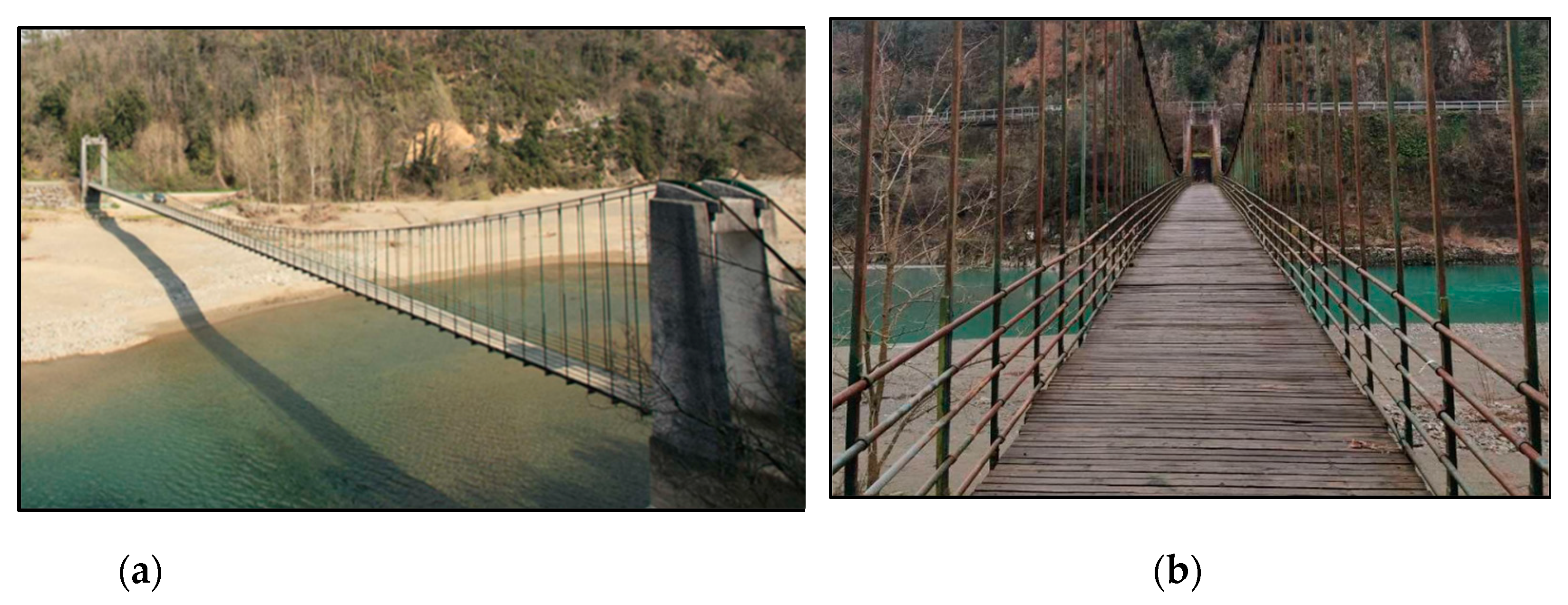
Figure 1 shows some examples of suspended bridges in the north of Italy. The Morca bridge (Figure 1b) is the only one allowing for light vehicular traffic: it was retrofitted in 2003 and an extensive program of non-destructive tests and analytical investigations on its dynamic behavior was carried out [3]. The Ramello footbridge (Figure 2), built in 1954 and located in the countryside of La Spezia in Italy, is another example of a historic suspension footbridge. The footbridge was employed for pedestrian crossing and light vehicles until 2019 and then closed, like many Italian bridges that were not considered safe after the collapse of the Morandi Bridge in Genova.
The aim of this study is to provide a structural and vibration serviceability assessment of the Ramello footbridge, using non-invasive surveys and low-cost equipment, that could assist public administration in the preservation of the structure. In order to avoid invasive interventions, the structural assessment is carried out in an indirect way by the modal testing of the footbridge and the comparison of the obtained modal properties with those derived from a Finite Element (FE) model built according to the nominal properties of the materials.
Modal testing can be carried out based on controlled input that is measured and used in the identification process (Experimental Modal Analysis, EMA), or on ambient vibration tests where only the response is measured and the force is due to environmental excitation (Operational Modal Analysis, OMA) [4]. A brief review of modal testing methods for bridges can be found, e.g., in [5]. With the exception of modern non-contact methods developed mainly for laboratory tests (e.g., [6]), EMA usually involves the excitation of the structure through contact methods. It has been applied for the modal identification of footbridges using hammer or shaker excitation (e.g., [7,8]). However, OMA testing techniques have now become attractive, due to their relatively low cost, speed of implementation, and the recent improvements in recording equipment and computational methods (e.g., [9,10,11,12,13,14]). The low amplitude of vibrations in operational conditions requires very sensitive, low-noise sensors and a high-performance measurement chain [4]. OMA testing techniques are based on the assumption that the excitation is a stationary random process with approximately white noise characteristics. Possible extensions to non-stationary long-term vibration monitoring have been proposed (e.g., [15]). Modal parameters can then be extracted, adopting frequency or time-domain methods [4]: the most commonly adopted are Peak Picking (PP) (e.g., [3,9]), Frequency Domain Decomposition (FDD) ([16], e.g., [3,13,14,17]), and Stochastic Subspace Identification (SSI) ([18], e.g., [8,11,12,14]). The identification of the structural modal parameters can also be employed in the framework of damage detection, since variations in the structural physical properties reflect variations of the modal parameters [19,20]. In particular, mode shapes are more sensitive to damage than natural frequencies, and recent research is focused on the detection of damage using damping [19].
Vibration serviceability assessment requires the evaluation of the level of vibration due to multi-pedestrian traffic, which calls for a probabilistic model of the loading (see e.g., [21,22,23,24,25,26,27]). However, current guidelines provide simplified equivalent loading conditions [12], e.g., an equivalent, uniformly-distributed resonant loading is suggested by SÉTRA [28].
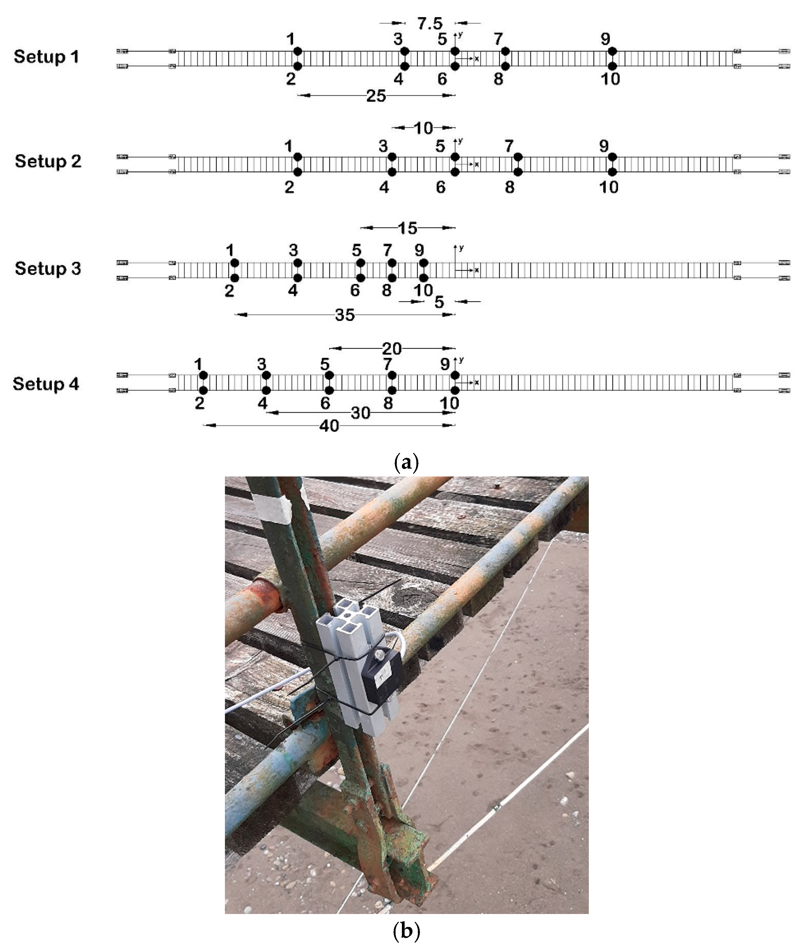
The experimental campaign on Ramello Footbridge includes a field survey of the footbridge geometry and element properties, ambient vibration tests, and live load tests of a single pedestrian crossing. The aim is to obtain the information necessary to build a reliable FE model, to get measurements for the dynamic identification of the footbridge, and to have a preliminary assessment of the level of vibration induced by pedestrians. Notwithstanding that the low amplitude of vibrations in operational conditions requires very sensitive, low-noise sensors, ambient vibrations are measured through low-cost equipment and the reliability of such measurement equipment is assessed. A comparison of the different techniques for modal parameters extraction is carried out in order to select the most appropriate one. Then, the FE model, built according to the field survey of the footbridge geometry, is validated against experimentally determined mode shapes and natural frequencies, and the correspondence of experimental and numerical modal properties is used as an indication of the structural health.
The paper develops through the following sections. Section 2 provides a detailed description of the footbridge geometry and element cross-sections estimated through field surveys. Section 3 describes the experimental campaign conducted in 2019 and 2021 and the subsequent identification of the footbridge dynamic properties by operational modal analysis. In Section 4, a 3D FE model of the footbridge is developed and calibrated based on the results obtained from ambient vibration tests. In Section 5, numerical simulations of the footbridge’s dynamic response under single pedestrian loading are carried out and a comparison with experimental results is performed. Moreover, the vibration serviceability of the footbridge is investigated based on SÉTRA guidelines. Finally, conclusions are outlined in Section 6.

2. Description of the Footbridge

The Ramello suspension footbridge (Figure 2 and Figure 3) was built in 1954 in the countryside of La Spezia in Italy. Due to the lack of drawing details, the geometric properties of the footbridge and its elements (Figure 4 and Figure 5) were obtained from field surveys. The footbridge has a span of length L = 90 m and a width of 2.28 m. Two main suspended cables, with a sag of 7.05 m, connect two reinforced concrete pylons from one side of the river to the opposite side. Each suspension cable is made of three individual spiral strands, with a nominal diameter of 40 mm. The main cables are anchored into the ground at distances of 7.9 m and 7.2 m from the left and right pylons, respectively. The bridge deck is supported by I-shaped transversal steel beams with a step of one meter (Figure 3a), which are suspended to the main cables by means of 89 hangers. The latter are made of rolled steel and have a C-shaped cross-section. The transversal steel floor beams have I-shaped cross-sections and a length of 2.4 m. They support two longitudinal rolled I-shaped steel beams, located at 1.78 m of distance, and three longitudinal timber planks, above which transverse timber planks form the floor (Figure 3a). Both transverse and longitudinal planks have a square cross-section with a side of around 80 mm.
Hangers are connected to floor beams by bolted connections (Figure 3b) and to main cables by means of steel sockets (Figure 3c), which keep the three strands in contact with each other, avoiding any relative displacement. Welded connections link the bottom flanges of the longitudinal beams to the top flanges of the transversal floor beams. Handrails are made of steel circular hollow sections (Figure 2b) and linked to the hangers with joints that restrain the vertical relative translational movement between the handrails and the hangers while enabling horizontal movement. Surface corrosion can be observed widely over the main structural elements (Figure 3b,c).
It is worth noting that the tension force of cables was not measured during the field surveys; therefore, it is considered an unknown parameter that is estimated based on the Finite Element (FE) model of the footbridge that will be discussed in the next sections.

3. Experimental Campaigns and Operational Modal Analysis

This section describes the experimental campaigns carried out in 2019 and 2021 with the aim of identifying the footbridge’s dynamic properties and measuring the footbridge’s dynamic response under the dynamic excitation of a single pedestrian.

3.1. Ambient Vibration Testing

Four ambient vibration tests with different measurement setup arrangements were conducted on the footbridge to detect its dynamic characteristics. Figure 6a shows the positions of accelerometers in the 4 setups. Suspended footbridges are characterized by extremely low natural frequencies, so the modes at risk of human-induced vibrations are usually higher modes, whose shapes are difficult to be correctly identified unless a great number of sensors are installed. Setup 1 was implemented in 2019, while the other three measurement setups were adopted in 2021 to identify more accurately the mode shapes of the footbridge. The low-cost equipment used for the tests included a 14-channel Labjack U6 data acquisition system with 10 TE Connectivity 4030 signal conditioned MEMS DC triaxial accelerometers that are able to measure accelerations in ±6 g range with a sensitivity of 333 mV/g and a nominal 0–200 Hz bandwidth. Figure 6b shows the detail of the accelerometers’ mounting: they were bolted to an aluminum profile, which was rigidly connected through tight bands at the bottom of the hanger as close as possible to the joint with the transversal beam.
The dynamic response of the footbridge was measured at 10 different locations in each measurement setup: vertical acceleration was measured at all the locations, while transverse accelerations were only at four locations (locations 1, 3, 7, and 9). In each measurement setup, the ambient vibrations were simultaneously recorded for one hour with a sampling frequency of 500 Hz.

3.2. Modal Identification of the Footbridge

The data processing and modal identification were performed by using MACEC, a MATLAB-based toolbox for the experimental modal analysis of structures [29]. The identification of the modal parameters was carried out by adopting the SSI, PP, and FDD techniques.
Figure 7, referred to as Setup 1, plots the stabilization diagram derived from the SSI technique (a), the averaged normalized power spectral density function for the identification based on the PP technique (b), and the singular values for FDD (c). In Figure 7a, the power spectral density functions of the measured accelerations are superimposed on the stabilization diagrams in order to verify that the identified poles correspond to the peaks in the acceleration spectrum. It can be deduced that most of the stable poles in Figure 7a correspond to peaks in the power spectral density function, also detected in Figure 7b,c.
Table 1 reports the natural frequencies identified through the three techniques, together with a synthetic description of the corresponding mode shape (L = Lateral, V = Vertical, T = Torsional; S = Symmetric, A = Asymmetric). It can be deduced that the natural frequencies identified with the PP and FDD techniques are coincident and they are generally in very good agreement with the ones identified by SSI. However, some of the vibration modes are identified only through the SSI technique. This circumstance is due to the weak ambient excitation and to the significant noise measured by the accelerometers, which does not allow for the clear identification of the peaks corresponding to some of the vibration modes through frequency-domain methods. The results in Table 1 show that the SSI technique is the one that allows the identification of the greater number of modes. Furthermore, frequency-domain methods require long time histories for the reliable identification of the modal damping ratios. Thus, in the following, results obtained by adopting SSI for all the tested setups are reported.
Figure 8 shows the stabilization diagrams extracted from Setups 2–4.
The identified dynamic characteristics of the footbridge are summarized in Table 2. The natural frequencies and damping ratios are obtained by combining and averaging the results extracted from different measurement setups. The detected modal shapes consist of one lateral bending mode, two torsional modes, and ten vertical bending modes that have symmetric or asymmetric shapes. The results show that the identified modes with frequencies greater than 1.3 Hz are quite stable and reliable since those modes were found in most of the ambient vibration measurements. There are four vertical bending modes (modes 9–12) whose natural frequencies fall within the frequency range of dynamic loading induced by the first walking harmonic [22]. Therefore, the resonant condition could occur for the footbridge due to walking pedestrians. The identified damping ratios of the modes at resonance risk for each Setup are reported in Table 3. It is worth noting that the damping ratios identified from Setups 2 to 4 are generally higher than those from Setup 1 and quite high with respect to the characteristic damping ratios of steel footbridges (around 0.5% [30]). In the Morca suspended footbridge [3], the identified damping ratios were quite high (2.73–7.69%) as well, and this unusual result was explained as due to energy dissipation in the connections between structural elements of the deck. Very large coefficients of variation of bridge damping ratios obtained from different experiments were also reported in [31], where it was observed that operating conditions affect the modal properties and, in particular, damping ratios are very sensitive to test and analysis methods. Therefore, damping average values are not considered fully reliable and will be verified and tuned within the simulation of the footbridge dynamic response (Section 5).

3.3. Measurements of Dynamic Response Due to a Single Pedestrian Crossing

In the experimental campaign in 2021, in addition to ambient vibration tests, three single walking load tests were carried out on the footbridge. Based on the results obtained from Setup 1 in 2019, a pedestrian, with a weight of 780 N, crossed the footbridge with his step frequency synchronized by a metronome to the frequencies of 1.5, 1.75, and 2.05 Hz, respectively. These frequencies do not exactly match the natural frequencies of the footbridge, which were correctly identified after the 2021 survey, but are very close to the resonant condition.
The layout of accelerometers in Setup 4 was used to record the acceleration of the footbridge deck in the lateral (L) and vertical (V) directions. As an example, the vertical acceleration response q ¨ ( t ) and its corresponding Fourier spectrum q ¨ ˜ ( f ) measured by accelerometer 2 (V2) during the passage of the pedestrian with a step frequency of 1.75 Hz are shown in Figure 9. The Fourier spectrum for this case shows that the dynamic response of the footbridge is dominated by the mode with the natural frequency of 1.803 Hz. Moreover, to exclude the effects of noises on the peak accelerations, the responses were lowpass filtered and peak accelerations were extracted from the filtered signal.
Table 4 reports the maximum acceleration responses obtained from these single-pedestrian walking load tests. The maximum transverse and vertical acceleration responses of 0.156 and 0.830 m / s 2 , respectively, are associated with a step frequency of 2.05 Hz.
The vibration serviceability of the footbridge under pedestrian walking loads can be evaluated based on the SÉTRA guidelines [28]. The guideline classifies footbridges according to four comfort levels based on maximum acceleration responses in both horizontal and vertical directions (Table 5). The vertical and lateral peak accelerations measured on the footbridge both fall within the mean comfort level. This result, obtained for a single pedestrian crossing, raises concerns about the comfort level due to the crossing of multiple pedestrians, which will be investigated in Section 5.

4. Finite Element Model of the Footbridge

The FE model of the footbridge was built with ANSYS software [32] to investigate numerically the dynamic behavior of the structure. The model was built based on the field surveys and then updated according to ambient vibration test results.
The main cables and the hangers were modeled using the 3D spar element “LINK180”. The effective steel area, density, modulus of elasticity, and Poisson’s ratio of each spiral strand of the main cables were taken as 945 mm2, 7850 kg/m3, 160 GPa, and 0.3, respectively. Furthermore, the longitudinal and transversal floor beams were modeled using the 3D elastic beam element “BEAM188” considering the modulus of elasticity and density as 210 GPa and 7850 kg/m3, respectively. The same material properties were assigned to the hangers. The timber boards and handrails were assumed as nonstructural elements and modeled with the concentrated mass element “MASS21”. The amount of concentrated mass applied at the deck nodes is estimated by assuming the values of density for timber boards and handrails as 700 and 7850 kg/m3, respectively. Table 6 summarizes the properties of all elements employed to build the numerical model.
Pylons were not modeled due to the high stiffness assumed at the pylon saddles: hence, the cables were restrained at the pylon position by means of rigid constraints that allow sliding in the longitudinal direction. The ends of the cables were restrained to the ground by pinned supports. Moreover, it was assumed that the hangers were hinged to the main cables and floor beams. Longitudinal and transversal beams were connected with fixed joints. Finally, both ends of the longitudinal beams were restrained to translations and rotations. The general view of the FE model of the footbridge is shown in Figure 10.

4.1. Preliminary Static Analysis

Suspended footbridges are characterized by non-linear behavior, due to the well-known geometric effects of the main cables [33]. Therefore, in their structural analysis, it is first necessary to determine the geometric configuration resulting from dead load and cable prestress. In the case of the Ramello footbridge, it is worth recalling that the surveyed geometry refers to the deformed configuration of the footbridge under dead load and prestress.
Since tension force in the cables has not been measured, it has been determined through a parametric study. Non-linear static analyses have been carried out for different values of the cable pretension T in the range 0–360 kN and vertical deflections q have been measured in different sections of the footbridge. Figure 11 plots the vertical deflections at the abscissas x = L/2 and x = L/3 along the deck for different values of the cable prestress. The value of prestress corresponding to the minimum deflection at both monitored positions has been retained for successive dynamic analyses. Specifically, a tension force in the main cables T = 180 kN was selected.

4.2. Modal Analysis

A modal analysis was performed on the footbridge model to extract its dynamic properties. The modal analysis was conducted after a nonlinear static analysis of the footbridge, subjected to dead loads and the pretension of the cables, in order to determine the geometric tangent stiffness matrix [2,34]. The natural frequencies of the first thirty global modes are summarized in Table 7.
From a direct inspection of Table 2 and Table 7, it is evident that ambient vibration tests did not allow the identification of the complete set of the lateral and torsional modes, but only of a very limited number of them. This is due to the evanescent excitation of such modes, provided only by the wind, which was very weak during the ambient vibration tests. For this reason, the validation of the numerical model, based on a comparison of modal parameters (i.e., natural frequencies and mode shapes) with the experimental estimates obtained from the SSI method, is limited to the vertical bending modes. The correlation of numerical and experimental mode shapes is investigated through the Modal Assurance Criterion (MAC), which is expressed as [35]:
MAC ( ϕ E , i , ϕ N , j ) = ( ϕ E , i T ϕ N , j ) 2 ( ϕ E , i T ϕ E , i ) ( ϕ N , j T ϕ N , j ) ,
where ϕ E , i is a vector that represents the i-th mode shape extracted experimentally from field vibration tests, ϕ N , j is a vector that represents the j-th numerical mode shape, and T stands for transpose. Generally, MAC values greater than 0.8 mean a very good match between the two mode shapes. Furthermore, the correlation of the two modes in terms of natural frequency can be investigated by calculating the percentage frequency error based on the following expression:
Δ f = f N f E f E × 100 [ % ] ,
where f E and f N are the experimental and numerical natural frequencies, respectively. According to Table 8, there is generally a good agreement between the numerically and experimentally identified modal parameters, with MAC values higher than 0.9 for almost all the considered modes, and frequency errors generally lower than 5%. This outcome demonstrates that the number of sensors and setups was sufficient to correctly detect the vertical bending modes, including higher-order ones. Moreover, the very good match between experimental and numerical mode shapes allows us to hypothesize that the footbridge is not interested in localized damage, despite the diffused surface deterioration of the structural elements. Figure 12 plots the mode shapes of the four vertical bending modes, whose frequencies fall within the range of walking excitation, while Figure 13 compares the experimental and numerical mode shapes reported in Table 8.

5. Vibration Serviceability Assessment

The dynamic response of the footbridge under single and multiple pedestrian loads is calculated in order to assess its vibration serviceability. It is assumed that the footbridge system is a linear mono-dimensional system, whose dynamics are described by the equation of motion:
m ( x ) 2 q ( x , t ) t 2 + C [ q ( x , t ) t ] + [ q ( x , t ) ] = f p ( x , t ) ,
where q(x,t) is the displacement of the footbridge, x is the abscissa along the bridge deck and t is the time, m(x) is the structural mass per unit length, C is the damping operator, is the stiffness operator, fp(x,t) is the external force per unit length. Under the hypothesis of classical damping, Equation (3) is usually solved by applying the principal transformation and assuming that the dynamic response is dominated by one mode of vibration:
q ( x , t ) = φ j ( x ) p j ( t ) ,
where φ j is the j-th mode shape of the footbridge and p j is the corresponding principal coordinate. The equation of motion of the j-th principal coordinate pj is expressed as:
p ¨ j ( t ) + 2 ξ j ω j p ˙ j ( t ) + ω j 2 p j ( t ) = F j ( t ) M j , F j ( t ) = 0 L f p ( x , t ) φ j ( x ) d x ,
where M j , ω j , ξ j , and F j ( t ) are the modal mass, circular natural frequency, modal damping ratio, and modal force of the j-th mode, respectively, and L is the span length.

5.1. Single Pedestrian Excitation

The mathematical model usually adopted to describe the vertical dynamic load due to a single pedestrian walking is defined by the following expression ([36,37]):
f p ( x , t ) = F p ( t ) · δ ( x c t ) ,
where c is the pedestrian speed, δ is Dirac delta function, and F p ( t ) is the time-varying vertical force induced by a single pedestrian, which is usually defined as a sum of Fourier harmonic components:
F p ( t ) = G + h = 1 H G α h s i n ( 2 π h f s t + ϕ h ) ,
where G is the static weight of the pedestrian, h is the order number of the harmonic, H is the total number of contributing harmonics, α h is the dynamic load factor (DLF) of the h-th harmonic, f s the step frequency (Hz), and ϕ h is the phase angle of the h-th harmonic. It is generally accepted and confirmed by experimental tests that the dynamic response of footbridges is mainly affected by the first walking harmonic. For normal walking speeds, the DLF of the first vertical harmonic is α 1 0.4 and pedestrian velocity can be calculated as c 0.9 f s (e.g., [30]).
The dynamic response of the footbridge due to a single pedestrian crossing can be obtained by numerically solving the equation of motion (5), with fp(x,t) expressed as in Equations (6) and (7).
As an alternative, the dynamic response of the footbridge can be approximately calculated based on the analytical solution proposed by Piccardo and Tubino [38], which predicts the dynamic response of the footbridge due to a single pedestrian crossing in resonant conditions. Specifically, the j-th principal coordinate p j is calculated in the nondimensional form, as follows:
p j ( t ˜ ) = A j ( t ˜ ) c o s ( t ˜ ) A j ( t ˜ ) = α h G 2 M j ω j 2 [ 0 t ˜ φ j ( Ω ˜ c τ ˜ ) exp ( ξ j τ ˜ ) d τ ˜ ] exp ( ξ j t ˜ ) ,
where the nondimensional parameters t ˜ and Ω ˜ c are defined as:
t ˜ = ω j t ;         Ω ˜ c = c ω j L .
In order to predict the dynamic response of the footbridge due to a single pedestrian crossing in the experimental tests described in Section 3.3, the dynamic response of the footbridge to a single pedestrian walking at 1.5, 1.75, and 2.05 Hz is estimated numerically (Equation (5)) and analytically (Equation (8)) considering as the mode of interest j the one whose frequency is the nearest to the excitation frequency, i.e., experimental modes 9, 10, and 11, respectively. In both cases, the adopted damping ratio is the average damping identified from the ambient vibration tests reported in Table 2. The obtained peak accelerations are reported in Table 9, compared with experimental results. Both numerical and analytical predictions are not very accurate, especially for step frequencies of 1.5 and 2.05 Hz, with a maximum error of about 35%. In order to obtain a more accurate prediction of the peak acceleration response, the damping ratios were modified within the range of values identified in the different setups (Table 3) in order to obtain a quite perfect match between numerical and experimental maximum accelerations. The modified damping ratios for the considered three bending modes are 2.7%, 0.78%, and 1.8%, respectively. Figure 14 plots an example of the vertical acceleration responses due to a single pedestrian crossing with a step frequency of 1.75 Hz obtained through numerical and analytical approaches with average and modified damping. From a comparison between Figure 14a,b, it can be deduced that assuming a modified damping ratio (0.78%) lower than the average value (1.732%, see Table 3), both the analytical and the numerical vertical responses increase. However, the increase in the numerical response (fs = 1.75 Hz) is larger than the increase in the analytical one (fs = 1.803 Hz). This circumstance is due to the fact that the modal force associated with the moving harmonic load (Equations (5)–(7)) can be decomposed into two harmonic components, one of which is closer to the resonance condition when fs = 1.75 Hz. Furthermore, comparing Figure 14b and Figure 9, it can be deduced that the experimentally measured time histories and the ones obtained numerically and analytically are not in perfect agreement. The difference can be due to many factors, such as the slight variations in the walking speed and step frequency in experimental tests, that are not taken into account by the analytical force model in Equations (6) and (7). Table 9 reports the peak accelerations obtained with the numerical and analytical approach by adopting the modified damping ratios. The results show that the modified damping generally allows us to obtain a more accurate analytical prediction of the peak response with a maximum error of about 16%. The obtained results confirm that, for the present footbridge, the dynamic response to a single pedestrian is mainly dominated by a single mode and that the analytical model in Equation (8) is able to predict the peak response with sufficient accuracy, despite the fact that resonant conditions were not perfectly achieved during the experimental tests.

5.2. Multiple Pedestrian Excitation

The serviceability of the footbridge is assessed based on the approach proposed by the SÉTRA guidelines [28]. According to SÉTRA, footbridges are classified into four classes, from urban footbridges with heavy traffic (Class I) to seldom-used footbridges (Class IV). Despite the Ramello footbridge belonging to Class IV, for which dynamic calculations are not required, the guideline suggests considering at least Class III for extremely lively footbridges to ensure a minimum amount of risk control. For Class III footbridges, serviceability assessment should be performed under the action of a sparse crowd, characterized by a pedestrian density ρ equal to 0.5 ped/m2. A resonant uniformly distributed harmonic load Fv(t) [N/m2] is defined as follows:
F v ( t ) = α G cos ( 2 π f j t ) N e q ψ , N e q = 10.8 ξ j ρ / ( B L ) , ψ = { ( f j 1.25 ) / 0.45 1.25 < f j < 1.7 1 1.7 < f j < 2.1 1 ( f j 2.1 ) / 0.2 2.1 < f j < 2.3 ,
where α G = 280 N, N e q is the equivalent number of perfectly synchronized pedestrians per square meter generating the 95th percentile of the peak acceleration response induced by random pedestrians, f j is the natural frequency of the j-th mode, B is the deck width, and ψ is a reduction factor to consider that the risk of resonance reduces if the footbridge frequency is outside the interval of 1.7–2.1 Hz for vertical vibrations. This load should be applied for each vertical mode at risk with the same sign as the one of the considered mode shape to obtain the most unfavorable effect. Moreover, the modal mass should be estimated while also taking into account the mass of pedestrians. The peak acceleration of the footbridge can be predicted with the following expression:
q ¨ m a x , v = α G N e q B 0 L φ j ( x ) d x 2 ξ j M j , t o t ,
where Mj,tot is the total modal mass of the footbridge and pedestrians.
The peak accelerations calculated for the three modes at resonance risk are reported in Table 10. According to Table 5, all the obtained values fall in the range of unacceptable comfort. It is worth pointing out that the simplified procedure proposed by the SÉTRA guidelines often leads to an overestimation of the structural response in the vertical direction since human–structure interaction is not taken into account. However, the very high values of peak accelerations suggest the need to further investigate the footbridge dynamic behavior under more realistic loading scenarios and to evaluate the possibility of installing suitable countermeasures.

6. Conclusions

This paper investigated the dynamic behavior and vibration serviceability of a historic suspension footbridge based on non-invasive low-cost modal testing and a numerical model.
The comparison among different frequency- and time-domain techniques for modal parameters extraction has shown that when using low-cost sensors with low vibration levels, the time-domain SSI method allows for the extraction of a larger number of modes. In particular, the operational modal analysis allowed the identification of 11 vibration modes, including one lateral, two torsional, and eight bending mode shapes within the frequency range of 0–2.6 Hz. The comparison of the modal characteristics of the numerical model and the ones estimated experimentally showed that ambient vibration tests carried out with low-cost sensors allowed a reliable identification of the bending modes, but not of the torsional and lateral ones, which were very weakly excited by ambient actions. The accordance between the experimentally identified natural frequencies and the ones obtained from the numerical model demonstrates that the stiffness of the elements corresponds to the one evaluated assuming standard values of the elastic modulus of steel, excluding a significant degradation of material properties. Furthermore, the good accordance between the experimental and numerical mode shapes confirms that the global structural behavior of the footbridge is well-captured by the numerical model and excludes significant local damages to the structural elements that would reflect on the identified mode shapes.
The footbridge is characterized by four lowly damped bending vibration modes in the range of step frequency typical of normal walking, and thus it is very sensitive to human-induced vibrations. The comparison between experimental accelerations and the ones estimated numerically based on a moving harmonic load model of a single pedestrian confirmed the reliability of such an approximated loading model. Finally, the serviceability assessment according to the SÉTRA guidelines showed that the footbridge would have an unacceptable comfort level under the crossing of a sparse crowd. The very high values of peak accelerations suggest the need to further investigate the footbridge dynamic behavior under more realistic loading scenarios and to evaluate the possibility of installing suitable vibration countermeasures (e.g., [39,40,41]).
In summary, the presented results have evidenced the following advantages (+) and drawbacks (−) of the non-invasive low-cost technology adopted:
+ The reliable identification of natural frequencies and mode shapes, in conjunction with the SSI modal identification technique;
+ The potential to draw considerations on the structural damage on the basis of the comparison between experimental and numerical modal properties;
+ The accurate estimation of the acceleration level for vibration serviceability assessment;
− Modal identification is limited to vertical bending modes;
− Modal damping ratios identified from ambient vibrations are very dispersed.
The last two issues are worthy of further investigation and the possibility to perform forced vibration tests or adopt higher-level equipment should be taken into consideration in order to also identify lateral and torsional modes and better estimate damping ratios.

Author Contributions

Conceptualization, F.T.; methodology, F.T.; software, E.B., A.M. and F.V.; validation, F.V.; formal analysis, F.T. and F.V.; resources, F.T.; data curation, E.B. and A.M.; writing—original draft preparation, E.B.; writing—review and editing, F.T. and F.V.; visualization, F.V.; supervision, F.T.; project administration, F.T. All authors have read and agreed to the published version of the manuscript.

Funding

This research received no external funding.

Institutional Review Board Statement

Not applicable.

Informed Consent Statement

Not applicable.

Data Availability Statement

Data sharing is not applicable to this article.

Acknowledgments

The Authors greatly acknowledge the technical support by Giancarlo Cassini, Giuseppe Riotto and Davide Burlando during the experimental campaign.

Conflicts of Interest

The authors declare no conflict of interest.

References

  1. Re, L. Cable Suspended: The Suspension Bridges of the 19th Century in Valsesia; Lindau: Turin, Italy, 1993. (In Italian) [Google Scholar]
  2. Bruno, L.; Venuti, F.; Nascè, V. Pedestrian-induced torsional vibrations of suspended footbridges: Proposal and evaluation of vibration countermeasures. Eng. Struct. 2012, 36, 228–238. [Google Scholar] [CrossRef]
  3. Gentile, C.; Gallino, N. Ambient vibration testing and structural evaluation of an historic suspension footbridge. Adv. Eng. Softw. 2008, 39, 356–366. [Google Scholar] [CrossRef]
  4. Brincker, R.; Ventura, C. Introduction to Operational Modal Analysis; John Wiley & Sons, Ltd.: Chichester, UK, 2015. [Google Scholar]
  5. Salawu, O.S.; Williams, C. Review of full-scale dynamic testing of bridge structures. Eng. Struct. 1995, 17, 113–121. [Google Scholar] [CrossRef]
  6. Scislo, L.; Guinchard, M. Non-Invasive Measurements of Ultra-Lightweight Composite Materials Using Laser Doppler Vibrometry System. In Proceedings of the 26th International Congress on Sound and Vibration, ICSV 2019, Montreal, QC, Canada, 7–11 July 2019. [Google Scholar]
  7. Brownjohn, J.M.W. Vibration characteristics of a suspension footbridge. J. Sound Vib. 1997, 202, 29–46. [Google Scholar] [CrossRef] [Green Version]
  8. Živanović, S.; Pavic, A.; Reynolds, P. Modal testing and FE model tuning of a lively footbridge structure. Eng. Struct. 2006, 28, 857–868. [Google Scholar] [CrossRef] [Green Version]
  9. Ren, W.-X.; Harik, I.E.; Blandford, G.E.; Lenett, M.; Baseheart, T.M. Roebling suspension bridge. II: Ambient testing and live-load response. J. Bridge Eng. 2004, 9, 119–126. [Google Scholar] [CrossRef]
  10. Caetano, E.; Cunha, A.; Magalhaes, F.; Moutinho, C. Studies for controlling human-induced vibration of the Pedro e Ines footbridge Portugal. Part 1 Assessment of Dynamic Behaviour. Eng. Struct. 2010, 32, 1069–1081. [Google Scholar]
  11. Hong, A.L.; Ubertini, F.; Betti, R. Wind analysis of a suspension bridge: Identification and finite-element model simulation. J. Struct. Eng. 2011, 137, 133–142. [Google Scholar] [CrossRef]
  12. Van Nimmen, K.; Lombaert, G.; De Roeck, G.; Van den Broeck, P. Vibration serviceability of footbridges: Evaluation of the current codes of practice. Eng. Struct. 2014, 59, 448–461. [Google Scholar] [CrossRef]
  13. Tubino, F.; Carassale, L.; Piccardo, G. Human-induced vibrations on two lively footbridges in Milan. J. Bridge Eng. 2016, 21, C4015002. [Google Scholar] [CrossRef]
  14. Lai, E.; Gentile, C.; Mulas, M.G. Experimental and numerical serviceability assessment of a steel suspension footbridge. J. Constr. Steel Res. 2017, 132, 16–28. [Google Scholar] [CrossRef]
  15. Lackny, L.; Scislo, L.; Guinchard, M. Application of Probabilistic Power Spectral Density Technique to Monitoring the Long-Term Vibrational Behaviour of CERN Seismic Network Stations. Vib. Phys. Syst. 2020, 31, 2020311. [Google Scholar]
  16. Brincker, R.; Zhang, L.M.; Andersen, P. Modal identification from output-only systems using frequency domain decomposition. Smart Mater. Struct. 2001, 10, 441–445. [Google Scholar] [CrossRef] [Green Version]
  17. Kordestani, H.; Xiang, Y.-Q.; Ye, X.-W.; Yun, C.-B.; Shadabfar, M. Localization of damaged cable in a tied-arch bridge using Arias intensity of seismic acceleration response. Struct Control Health Monit. 2020, 27, e2491. [Google Scholar] [CrossRef]
  18. Van Overschee, P.; De Moor, B. Subspace Identification for Linear Systems: Theory, Implementation, Applications; Springer: New York, NY, USA, 1996. [Google Scholar]
  19. Cao, M.S.; Sha, G.G.; Gao, Y.F.; Ostachowicz, W. Structural damage identification using damping: A compendium of uses and features. Smart Mater. Struct. 2017, 26, 043001. [Google Scholar] [CrossRef]
  20. Casas, J.R.; Moughty, J.J. Bridge damage detection based on vibration data: Past and new developments. Front. Built Environ. 2017, 3, 1–12. [Google Scholar] [CrossRef] [Green Version]
  21. Racic, V.; Pavic, A.; Brownjohn, J.M.W. Experimental identification and analytical modelling of human walking forces: Literature review. J. Sound Vib. 2009, 326, 1–49. [Google Scholar] [CrossRef]
  22. Živanović, S.; Pavic, A.; Reynolds, P. Vibration serviceability of footbridges under human-induced excitation: A literature review. J. Sound Vib. 2005, 279, 1–74. [Google Scholar] [CrossRef] [Green Version]
  23. Brownjohn, J.M.W.; Pavic, A.; Omenzetter, P. A spectral density approach for modelling continuous vertical forces on pedestrian structures due to walking. Can. J. Civ. Eng. 2004, 31, 65–77. [Google Scholar] [CrossRef] [Green Version]
  24. Piccardo, G.; Tubino, F. Simplified procedures for vibration serviceability analysis of footbridges subjected to realistic walking loads. Comput. Struct. 2009, 87, 890–903. [Google Scholar] [CrossRef]
  25. Caprani, C.C.; Keogh, J.; Archbold, P.; Fanning, P. Enhancement for the vertical response of footbridges subjected to stochastic crowd loading. Comput. Struct. 2012, 102–103, 87–96. [Google Scholar] [CrossRef] [Green Version]
  26. Chen, J.; Wang, J.; Brownjohn, J.M.W. Power spectral density model for pedestrian walking load. J. Struct. Eng. 2019, 145, 04018239. [Google Scholar] [CrossRef]
  27. Wang, J.; Chen, J.; Yokoyama, Y.; Xiong, J. Spectral model for crowd walking load. J. Struct. Eng. 2020, 146, 04019220. [Google Scholar] [CrossRef]
  28. SETRA. Footbridges–Assessment of Vibrational Behaviour of Footbridges under Pedestrian Loading; Technical Department for Transport, Roads and Bridges Engineering and Road Safety, Ministry of Transport and Infrastructure: Paris, France, 2006.
  29. De Roeck, G.; Peeters, B. MACEC2. 0—Modal Analysis on Civil Engineering Constructions; Department of Civil Engineering, Catholic University of Leuven: Leuven, Belgium, 1999. [Google Scholar]
  30. FIB. Guidelines for the Design of Footbridges; Bulletin 32, International Federation for Structural Concrete: Lausanne, Switzerland, 2005. [Google Scholar]
  31. Alampalli, S. Effects of testing, analysis, damage, and environment on modal parameters. Mech. Syst. Signal Process. 2000, 14, 63–74. [Google Scholar] [CrossRef]
  32. ANSYS. Academic Teaching Mechanical User Manual; Release 2022 R1; ANSYS: Canonsburg, PA, USA, 2022. [Google Scholar]
  33. Brownjohn, J.M.W. Observations on non-linear dynamic characteristics of suspension bridges. Earthq. Eng. Struct. Dyn. 1994, 23, 1351–1367. [Google Scholar] [CrossRef]
  34. Bruno, L.; Venuti, F.; Scotti, A. Limit of hanger linearity in suspension footbridge dynamics: A new section model. J. Sound Vib. 2011, 330, 6387–6406. [Google Scholar] [CrossRef]
  35. Maia, N.M.M.; Silva, J.M.M. Theoretical and Experimental Modal Analysis; Research Studies Press: Taunton, UK, 1997. [Google Scholar]
  36. Allen, D.E.; Murray, T.M. Design criterion for vibrations due to walking. Eng. J. 1993, 30, 117–129. [Google Scholar]
  37. Bachmann, H.; Ammann, W. Vibrations in Structures Induced by Man and Machines; Iabse: Zurich, Switzerland, 1987; Volume 3. [Google Scholar]
  38. Piccardo, G.; Tubino, F. Dynamic response of Euler-Bernoulli beams to resonant harmonic moving loads. Struct. Eng. Mech. 2012, 44, 681–704. [Google Scholar] [CrossRef]
  39. Banas, A.; Jankowski, R. Experimental and numerical study on dynamics of two footbridges with different shapes of girders. Appl. Sci. 2020, 10, 4505. [Google Scholar] [CrossRef]
  40. Bayat, E.; Bayat, M.; Hafezzadeh, R. Numerical performance assessment of Tuned Mass Dampers to mitigate traffic-induced vibrations of a steel box-girder bridge. Struct. Eng. Mech. 2021, 78, 125–134. [Google Scholar]
  41. Van Nimmen, K.; Verbeke, P.; Lombaert, G.; De Roeck, G.; Van Den Broeck, P. Numerical and experimental evaluation of the dynamic performance of a footbridge with tuned mass dampers. J. Bridge Eng. 2016, 21, C4016001. [Google Scholar] [CrossRef]
Figure 1. (a) Footbridge “Gaietta”, Millesimo, Italy (photo by F. Venuti); (b) Morca bridge, Italy; (c) Footbridge of Vocca Island, Italy; (d) Footbridge at Millesimo, Italy (photo by F. Venuti).
Buildings 12 00732 g001
Figure 2. General views of the Ramello footbridge: (a) lateral view and (b) longitudinal view.
Buildings 12 00732 g002
Figure 3. Details of the bridge deck (a), connections between the hanger and deck transversal beam (b) and between the hanger and main cable (c).
Buildings 12 00732 g003
Figure 4. Elevation of the footbridge.
Buildings 12 00732 g004
Figure 5. Cross-sections and dimensions of the footbridge structural elements (in mm).
Buildings 12 00732 g005
Figure 6. Layout and location of accelerometers along the bridge deck for different measurement setups (in m) (a) and detail of the accelerometers’ mounting (b).
Buildings 12 00732 g006
Figure 7. Setup 1: Stabilization diagram (a), averaged power spectral density functions (b), singular values (c).
Buildings 12 00732 g007
Figure 8. Stabilization diagrams of Setups 2 (a), 3 (b) and 4 (c) obtained from the SSI technique and power spectral density functions of the measured accelerations (in grey).
Buildings 12 00732 g008
Figure 9. The measured (a) and filtered (c) vertical acceleration and Fourier spectrum (b) by accelerometer 2 (V2) due to a single pedestrian crossing with a step frequency of 1.75 Hz.
Buildings 12 00732 g009
Figure 10. General view of the FE model of the footbridge.
Buildings 12 00732 g010
Figure 11. Vertical deflections at x = L/2 and x = L/3 for different values of cable prestress (filled markers identify the selected value of prestress).
Buildings 12 00732 g011
Figure 12. Mode shape of modes sensitive to walking excitation (obtained through FE modeling).
Buildings 12 00732 g012
Figure 13. Comparison between experimental and numerical mode shapes.
Buildings 12 00732 g013
Figure 14. Time history of the acceleration responses by the numerical and analytical solutions predicted with average (a) and modified damping (b) during a single pedestrian crossing with a step frequency of 1.75 Hz.
Buildings 12 00732 g014
Table 1. Setup 1: Modal parameters of the footbridge obtained from the different identification techniques.
ModeMode ShapeFrequency SSI [Hz]Frequency PP [Hz]Frequency FDD [Hz]
1LS0.260--
2VA0.557--
3VS0.6260.6250.625
4VA0.8870.8900.890
5TS1.0641.0621.062
6VA1.3601.3671.367
7VS1.5191.5151.515
8TS1.7681.7571.757
9VA1.8381.9051.905
10VS2.1062.1082.108
11TS2.259--
12VA2.356--
13VS2.6332.6242.624
Table 2. Average identified modal parameters using the SSI technique.
ModeMode ShapeSetupFrequency [Hz]Damping [%]
1LS10.2592.051
2VA10.562.462
3VS1,2,30.6123.041
4VA1,2,40.8943.018
5TA30.9223.600
6TS1,2,31.0622.500
7VS41.0893.024
8VA3,41.3452.681
9VS1,2,3,41.5312.157
10VA1,2,3,41.8031.732
11VS1,2,3,41.9801.585
12VA1,2,3,42.3110.766
13VS1,2,3,42.5230.177
Table 3. Identified damping ratios [%] for each setup and average values for the modes at resonance risk.
Frequency [Hz]Setup 1 [%]Setup 2 [%]Setup 3 [%]Setup 4 [%]Average [%]
1.5311.1673.2481.3442.8692.157
1.8030.782.5881.5042.0581.732
1.980.5012.6611.4481.7321.585
2.3110.5511.6020.6170.2940.766
Table 4. Maximum acceleration responses due to different walking load tests [m/s2].
Walking TestsStep Frequency
Accelerometer1.5 Hz1.75 Hz2.05 Hz
V10.4070.6550.703
V20.5040.7550.794
V30.2640.6730.589
V40.2980.6470.546
V50.3520.5520.737
V60.3600.4720.730
V70.6710.4780.573
V80.6920.4680.800
V90.7700.3120.830
V100.8080.1840.770
L10.0380.0350.061
L30.0320.0330.156
L70.0280.0320.054
L90.0450.0300.060
Table 5. Comfort levels and corresponding acceleration limits defined by SÉTRA [28].
Comfort LevelVertical
Acceleration Limit [m/s2]
Horizontal
Acceleration Limit [m/s2]
Maximum<0.5<0.15
Mean0.5–10.15–0.3
Minimum1–2.50.3–0.8
Unacceptable>2.5>0.8
Table 6. Element properties.
Structural
Element
ANSYS
Element
A [m2]Iy [m4]Iz [m4]Mass [kg]
CableLINK1800.284 × 10−2---
HangerLINK1800.729 × 10−3 -
Transversal beamBEAM1881.434 × 10−32.18 × 10−61.58 × 10−7-
Longitudinal beamBEAM1881.192 × 10−31.08 × 10−61.02 × 10−7-
HandrailMASS21---15
Timber boardMASS21---60
Table 7. Modal parameters of the footbridge obtained through FE modeling.
ModeMode ShapeFrequency [Hz]ModeMode ShapeFrequency [Hz]
1LS0.30419VS1.469
2VA0.43521TA1.499
3TA0.50423TS1.692
4LA0.56824VS1.699
5VS0.60725LA1.723
6TS0.70626VA1.766
7LS0.84829TA1.961
8VA0.85830LS2.010
11TA0.98931TA2.015
12VS1.04632VS2.030
15LA1.14533VA2.256
16TS1.20735LA2.301
17VA1.30236TS2.303
18LS1.43238VS2.532
Table 8. Comparison of numerical and experimental modal parameters for bending vibration modes.
Numerical ResultsExperimental Results Δ f [%]MAC
ModeFrequency (Hz)ModeFrequency (Hz)
20.43520.560−22.320.985
50.60730.612−2.090.996
80.85840.894−4.070.994
121.04671.089−3.990.893
171.30281.344−1.380.975
191.46991.531−3.390.913
261.766101.803−0.800.990
322.030111.9802.530.941
332.256122.310−1.920.994
382.532132.520−1.090.736
Table 9. Comparison of peak acceleration responses [m/s2] obtained through experimental, numerical, and analytical approaches for a single pedestrian crossing at different step frequencies.
ξAverageξModified
fs [Hz]ExpNumericalAnalyticalNumericalAnalytical
1.50.810.9060.9640.7980.885
Error [%]13.1220.39−0.3710.45
1.750.760.49170.4850.7290.629
Error [%]−34.87−35.76−3.41−16.69
2.050.830.8950.7860.8350.744
Error [%]7.78−5.330.57−10.34
Table 10. Peak accelerations due to sparse traffic according to SÉTRA guidelines.
fj = 1.53 Hzfj = 1.80 Hzfj = 1.98 Hz
q ¨ m a x , v [m/s2]5.578.207.56
Publisher’s Note: MDPI stays neutral with regard to jurisdictional claims in published maps and institutional affiliations.

