1. Introduction
Asphalt pavement compaction is an essential step in the asphalt road construction process, affecting the strength and stability of the asphalt mixture and, as a result, the final road service quality and service life [
1]. The field compaction process is typically divided into three stages: preliminary compaction, repeated compaction, and final compaction. The preliminary compaction process has a direct influence on the asphalt pavement, which should be compacted and stabilized to fulfill technical criteria and create favorable circumstances for the following steps [
2]. The asphalt mix paver is used for the preliminary compaction process, which is to lay the asphalt mixture according to engineering technology specifications with a certain width and thickness uniformly on the base’s surface, as well as to perform preparatory vibration compaction and screeding of the paving [
3].
There are several different aspects that influence the compaction process, including the properties of the mixture composition, the environmental conditions, and the compaction method. As aggregate angularity, size, and hardness increase, the compactive effort required to achieve a given density increases [
4]. During compaction, the gaps between the particles shrink as the air between the asphalt particles is continuously removed. It also means that the density of the pavement increases, which has been extensively measured and studied, both in laboratory experiments and field tests.
Existing investigations often employ traditional tests or imaging techniques to evaluate laboratory samples or drilled cores from field tests. For example, the X-ray computerized tomography (CT) scanning method has been widely employed due to its capacity to analyze the interior macroscopic characteristics of rock samples. It is also applied as an auxiliary tool for microscale petrography [
5,
6]. Later, non-destructive density gauges emerged, such as nuclear and non-nuclear gauges, to partially replace laboratory core measurements. Although the nuclear gauge’s early concerns of being clumsy and heavy have been resolved, and its accuracy and operator safety have been enhanced, the need to have a license to operate this instrument must still be satisfied, which raises the threshold for administering lab tests. Nonnuclear gauges increasingly won over because of their user-friendly approach, speed, robust reproducibility, and slight standard variation across tests, as well as additional advantages such as ease of licensing [
7,
8]. Besides nuclear and nonnuclear gauges, ground-penetrating radar (GPR) [
9,
10] is a non-destructive testing tool that employs radar pulses to detect and picture conditions beneath the ground surface and is also frequently explored. Because of its high-speed, uninterrupted features, and the richness of pavement information it can provide, GPR is regarded as one of the most promising tools. However, the application of GPR to forecast the in-place density of asphalt mixtures is still in its early stages, and its performance requires further validation before it can be employed in practical situations [
11,
12].
However, both laboratory experiments and field tests have limitations. The data produced from laboratory experiments often deviate from the field tests, despite the ease of analysis and protection from interference. While the coring process can offer precise information regarding pavement density, it is irreversible and risks inflicting harm to the pavement and reducing its service life. In addition, the drilling of samples is done after the compaction of the pavement rather than during compaction. Gauges, whether nuclear or non-nuclear, are non-destructive. However, they must be artificially operated on the ground to collect relevant data, and they are subject to outside interference. Furthermore, these methods can only be used to measure and evaluate the pavement after the compaction work has been fully completed. In order to optimize the intervention timing, the ability to monitor or simulate in real-time the changes in the pavement condition during the time period between the paver paving and the roller compaction is desired.
Recently there have been a number of computationally assisted methods. Asphalt mixtures can be effectively simulated and studied during the paving process, such as analytical methods, continuum-based methods - finite element method (FEM), and discontinuity-based methods - discrete element method (DEM) [
13,
14]. These methods overcome the limitations of traditional research methods and are repeatable and stable simulation methods. The mechanical response of asphalt mixtures compacted by various ways was investigated using finite element simulations in the work by Liu et al. [
15]. Experiments, digital image processing techniques, and FEM were used to compare and evaluate specimens produced using various compaction methods (including field compaction, Aachen compaction, and Marshall compaction). The Aachen compaction machine specimens were found to have a greater association with the field specimens than the specimens from the Marshall compaction. To explore the influence of compaction variables on air void distribution, Chen et al. used an open source DEM program to construct virtual digital specimens [
16]. By preprocessing the particles and boundaries, the impacts of aggregate characteristics and compaction method on compaction were investigated, and the findings of the DEM simulation corresponded well with laboratory test results as well as data from the literature. In the study by Qian et al., the compaction process of asphalt mixtures was investigated by laboratory tests and DEM simulations. The meso structural changes of asphalt mixtures were traced. Although the problem that the horizontal size distribution of particles is not entirely uniform still exists, it was confirmed that DEM simulation is an effective method to evaluate the compaction effect during compaction [
17]. In addition, Wang et al. investigated the fundamental mechanics of asphalt compaction using FEM and DEM, respectively [
18]. FEM was shown to accurately model the reduction of air voids. DEM can individually address the properties of each component, in contrast to FEM, which uses the continuum type modeling. DEM may, however, provide a rudimentary grasp of particle kinematics and relative binder-to-aggregate hardness. In addition, the mechanical properties of asphalt mixture samples produced by various compaction techniques may differ even if the degree of compaction is the same. There are, however, non-negligible limitations of both FEM and DEM when considering the interaction between asphalt mix and paver during real-time pre-compaction. When using a continuous method like FEM, the behavior of individual asphalt particles cannot be described in detail. When applying DEM, each asphalt particle is modeled as a separate entity, which is very suitable for studying phenomena occurring on the particle diameter length scale. However, the complex particle geometry and arrangement make the computational cost enormous.
The coupled FEM-DEM approaches are considered to improve the problems associated with the use of either method alone. One method of the FEM-DEM approaches is that the discrete elements are separated into independent finite element meshes, which considers each discrete element as a deformable continuum and separates them according to their existing discontinuity surface. Newton’s second law determines the motion of individual components based on the unbalanced forces or unbalanced moments imparted on them. In contrast, the interaction between elements is governed by the contact transients between the blocks, which are processed in the same approach as the DEM. The deformation coordination criterion between elements is not required, and elements may be translated and rotated [
19]. To describe the behavior of granular media, a rigorous hierarchical FEM-DEM coupling method was adopted by Guo and Zhao [
20].It is illustrated that the proposed method can reproduce interesting experimental observations that are difficult to capture using traditional FEM or pure DEM simulations, such as the onset of the shear zone under smooth, symmetric boundary conditions, the noncoaxial particle response, the significant expansion and rotation at the shear zone’s edge, and the critical state reached within the shear zone. Du et al. [
21] created an innovative coupled FEM-DEM method to successfully simulate the numerical analysis of the Solid Grain Media Forming (SGMF) technological process. For the first time, it addressed the issue of elastic-plastic mechanics, the contact between a continuum and a discontinuity. Moreover, Orosz and Zwierczyk [
22] investigated coupled FEM-DEM simulations of railroad sleepers in the instance of gravel roadbeds, revealing patterns in the stress state of concrete sleepers under typical loading.
In order to monitor the interaction between the material and the paving equipment, a modelling methodology was developed in this study through a coupled FEM-DEM method. The general-purpose FE software ABAQUS was used for the modelling. FEM was used in large areas of this simulation, in this case the pavement base and the paver, and DEM in smaller, more localized areas, here was the asphalt mixture component. In particular, each DEM particle representing an aggregate in the preliminary compaction was modeled with a single-node element. These elements were rigid spheres with specified radii and had displacement and rotational degrees of freedom. General contact definitions were extended to include interactions among DEM particles and interactions between DEM particles and FE-based (or analytical) surfaces. In the following sections, the process of preliminary compaction modelling is described in detail. After many attempts, the optimal modelling parameters are determined, and the results generated by the numerical simulations are compared between the actual situation and previous studies, which involved the influence of factors such as different material parameters of the asphalt mixture and different operating parameters of the paver. Based on the results and discussion, conclusions are drawn, which is beneficial to further investigation on the material compaction behavior and its mechanical performance afterwards. It is worth mentioning that as preliminary research for simulating the compaction, some simplifications and assumptions were adopted in the FEM-DEM coupled method. The actual shapes of the aggregates were instead uniformly substituted by spheres, which decreases the degree to which the simulation is accurate in comparison to the real scenario to some extent. In addition, ambient temperature and wind velocity are supposed to be considered in the simulation to get close to the real condition of pavement construction. These limitations should be considered for future research.
2. Modelling of Preliminary Compaction Based on FEM-DEM Coupled Method
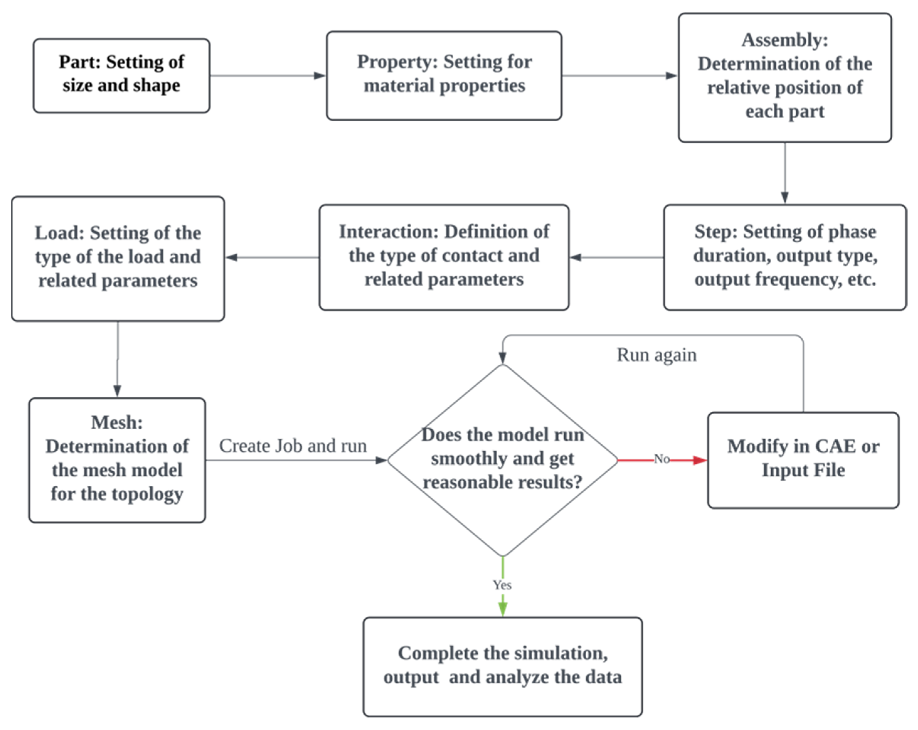
In this chapter, the detailed modeling process of the preliminary compaction in ABAQUS will be introduced. ABAQUS is one of the world’s most advanced nonlinear finite element software and provides a simple uniform interface for creating, submitting, monitoring, and analyzing simulation results. It has progressed to the point where discrete element simulation is now available with this finite element simulation program [
23]. The simulation flowchart is shown in
Figure 1. Some main steps of the modelling procedure will be introduced in the following sections.
2.1. Creation of the Different Parts of the Model
One of the key parts of the compaction model is the aggregates, which were generated by the particle generator in ABAQUS. The particle generator enables a modeling technique in which the DEM is checked only when the particles reach a defined area, which simplifies the construction of the model while improving the computational efficiency [
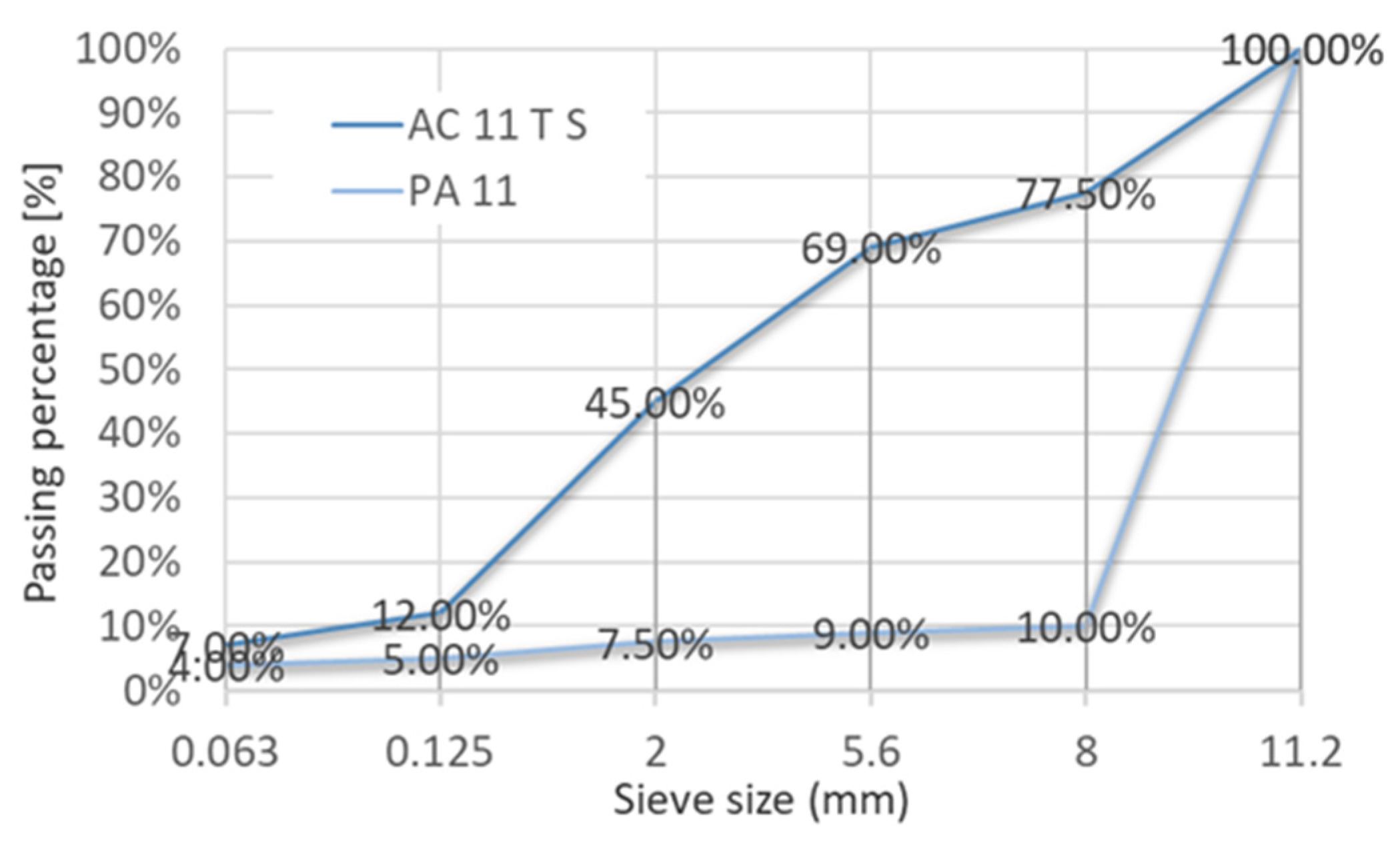
24]. The particles are released in a direction perpendicular to the inlet surface of the particle generator and the flow rate should be determined according to the paving speed. In this study, only one particle generator was used. In order to improve the computational efficiency, the morphology of the aggregates was simplified to spheres, which cannot fully simulate the aggregate interlocking happening during compaction. The approach to simplify the geometry of the aggregates while keep their main features will be studied in the future. The element type of particles released by the particle generator was PD3D, representing discrete particles. In order to investigate the influence of the gradation of the asphalt mixture on the pre-compaction, two different asphalt mixtures, a dense-graded mixture AC11 and a gap graded mixture PA11, were simulated and their gradations are shown in
Figure 2.
The distribution of the particles size was controlled by a probability density function (PDF). Different forms of probability density functions, such as uniform, normal, lognormal, piecewise linear, and discrete distributions, are supported by the particle generator. In this case, discrete distributions were used in the PDF. The three largest size levels in the gradation were taken into account in the simulation, and the maximum number of the particles to be released was set as 10,000 based on trade-offs between accuracy and computational cost. The density of the aggregates was set to 2.85 × 10⁻⁹ ton/mm3, and the Young’s modulus and Poisson’s ratio were set to 20,800 MPa and 0.3, respectively.
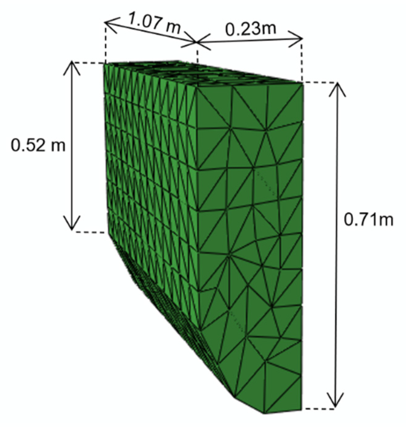
In this study, the other parts including the base and the paver were created and discretized by FEM. The base that was ready to be compacted on by the paver was simplified to a shell 3.42 m wide and 17.14 m long without thickness, on which two shells 0.4 m high and around 1.14 m apart were created as a fence to designate the paver’s work path. As a result of the impact of vibration paver vibration, the unit line pressure is greatly improved, and when the vibration paver continues to make rapid impact on the surface, the same frequency of pressure waves penetrates into the material layer, causing the material particles to move, rearrange, and become denser as a result. Therefore, vibratory pavers are becoming more popular and will be used in this model. The paver has been diminished to its two most fundamental components: the tamper and screed. When the tamper portion was set as indicated in
Figure 3, the screed was set as a hollow rectangle with a length of 1.27 m, a width of 1.07 m, and a height of 0.72 m. Since the base, tamper, and screed are assumed as rigid bodies, they do not need to be assigned any material properties.
2.2. Assembly of the Different Parts and Their Interaction
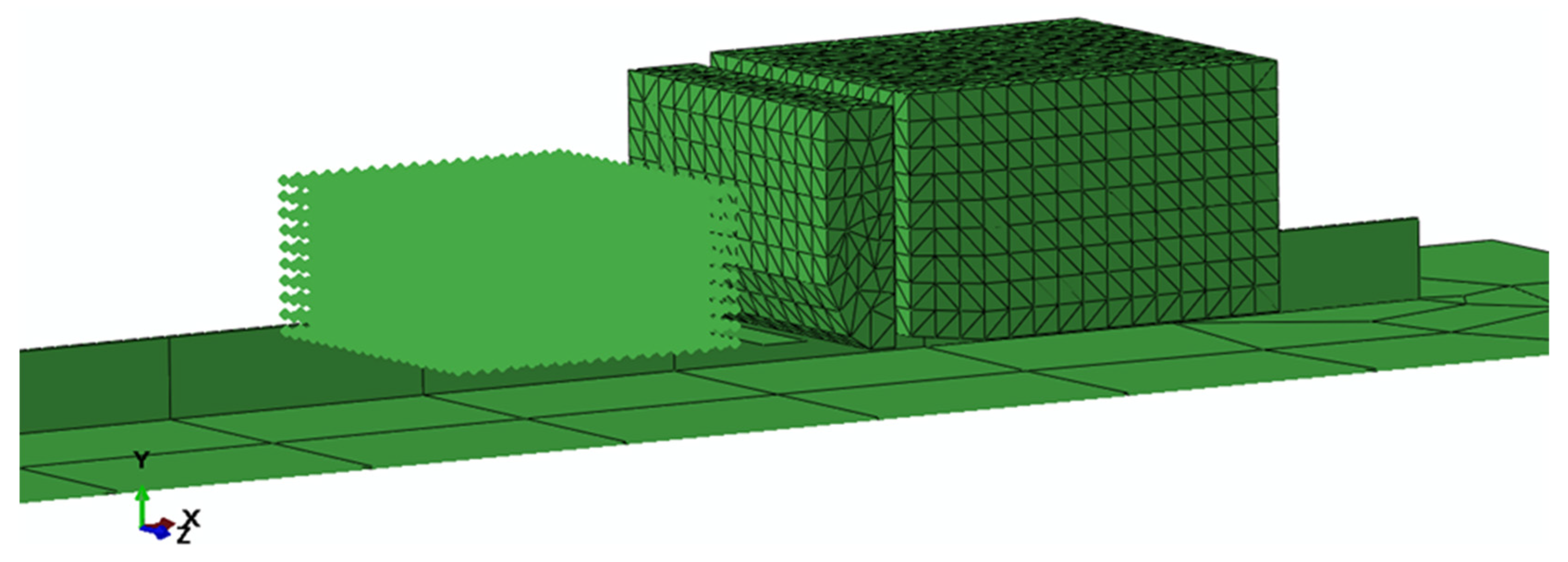
The parts including particle generator, the base, and the paver were assembled together in ABAQUS. As shown in
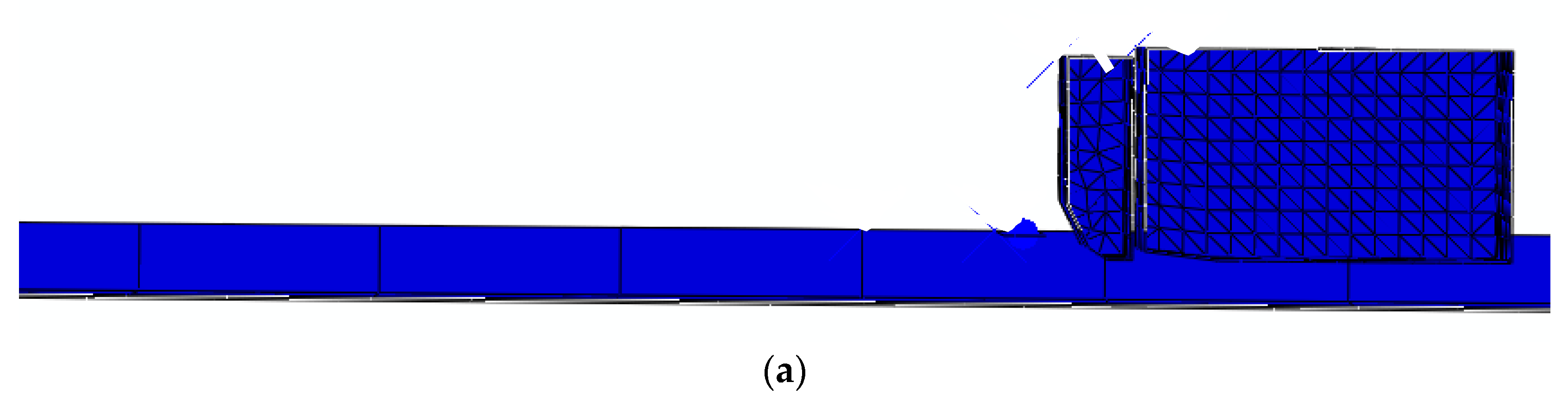
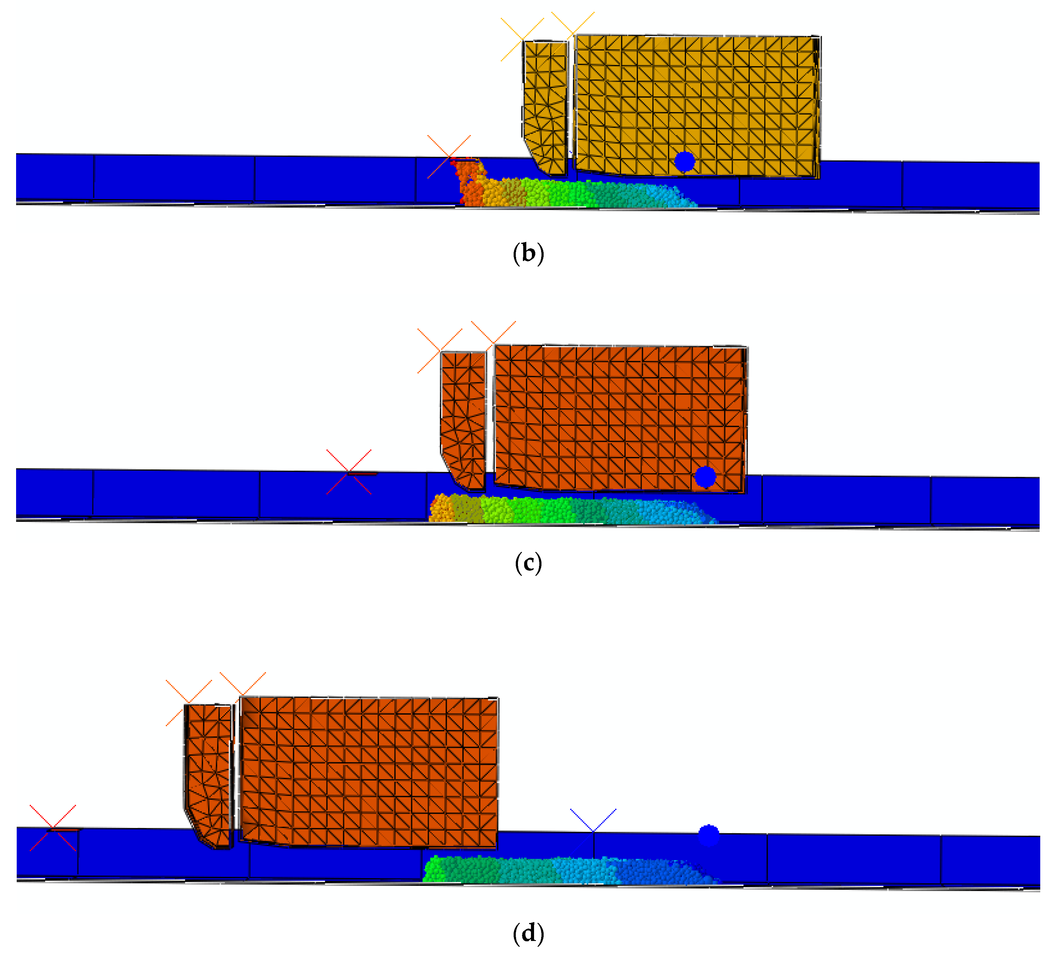
Figure 4, the paver was placed on the far right side of the base and screed to the left in the forward direction. The tamper and the part generator were placed in the middle of the specified route. The distance between the lowest point of the tamper and the screed and the base was set at 0.4 m, which was the thickness of the asphalt mixture initially required to be paved. In front of the paver, a particle generator serves as both an unloading truck and as paver blades. The particle generator has almost the same width as the paver body, ensuring that the particles are equally distributed over the road to be paved. Furthermore, it is located near to the base (approximately 48 cm), ensuring that the asphalt particles do not bounce hard on the base after being released owing to their high velocity, but leaving enough space for the particles to aggregate on the base.
The coordinate system of the model should be referred to in order to sort out the subsequent directions to which the data refers. As shown in the
Figure 4, the negative direction of x is the forward direction of the paver; the negative direction of y is the direction of the falling asphalt particles; and the z direction is perpendicular to the forward direction of the paver in the horizontal direction.
The contact between particle and tamper, particle and screed was simplified as Hertzian contact [
25], defined with a limit value of Hertzian stiffness of 2000 MPa and a friction coefficient of 0.7. To prevent the particles from moving away from the base due to the paver’s activity, or from sliding on the base, the connection between the particles and the base should include an extra force based on the Hertzian contact that causes the particles to cling to the base. As a result, the contact type between the particles and the base was set to the JKR model [
26], with a surface energy of 10 mJ per unit area limit value of stiffness of 100 MPa and a friction coefficient of 0.95. Also, the contact type between the particle and the particle was set to the JKR model, with a surface energy of 10 mJ per unit area, limit value of stiffness of 100 MPa, and a friction coefficient of 0.65. The JKR model was proposed by Johnson, Kendall, and Roberts in 1971, and allows for tensile forces to develop due to surface adhesion. It is widely used to describe viscous contacts, and therefore the JKR model was used in this study.
2.3. Definition of the Computational Steps and Boundary Conditions
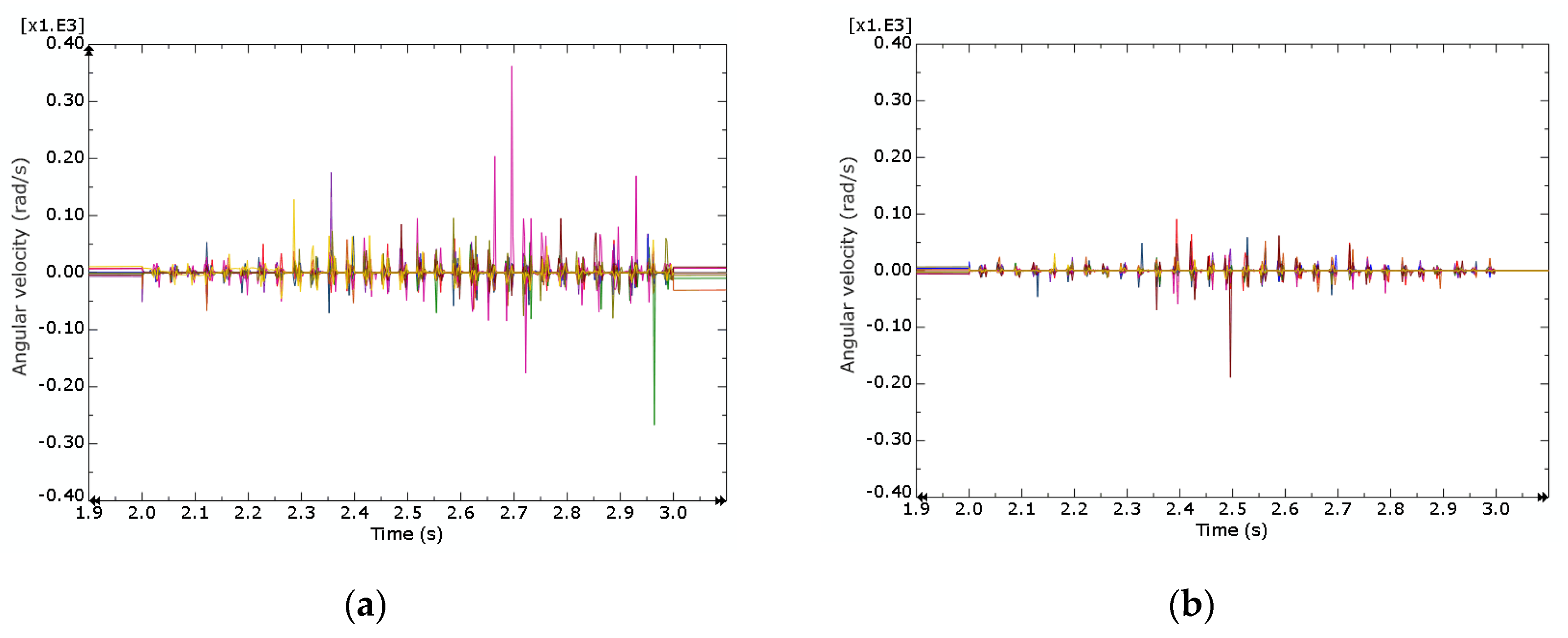
Since the model required the observation of pavement condition changes before and after initial compaction, a certain length of the pavement that the paver was working steadily on could be observed, which meant that the duration of the step needed to be sufficient for the paver to travel over the specific area. Additionally, the step time is proportional to the paver’s forward speed. The speed of the tamper and the screed were both set at speeds of 4 m/min, 5 m/min, 6 m/min to investigate the effect of the paving speed on the paving process. Furthermore, the screed and tamper were set to a periodic, uniform amplitudes of 1 cm and 0.8 cm, with frequencies of 20 Hz and 30 Hz, respectively, which enabled the pavement to be compacted and screeded to increase its compactness, reducing the number of compaction passes by the roller and improving the pavement’s surface quality.
4. Conclusions and Outlook
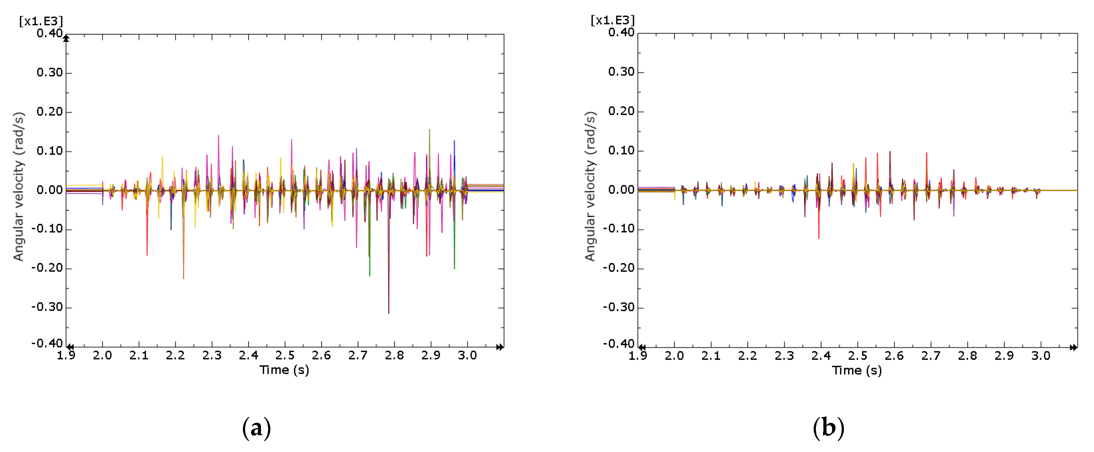
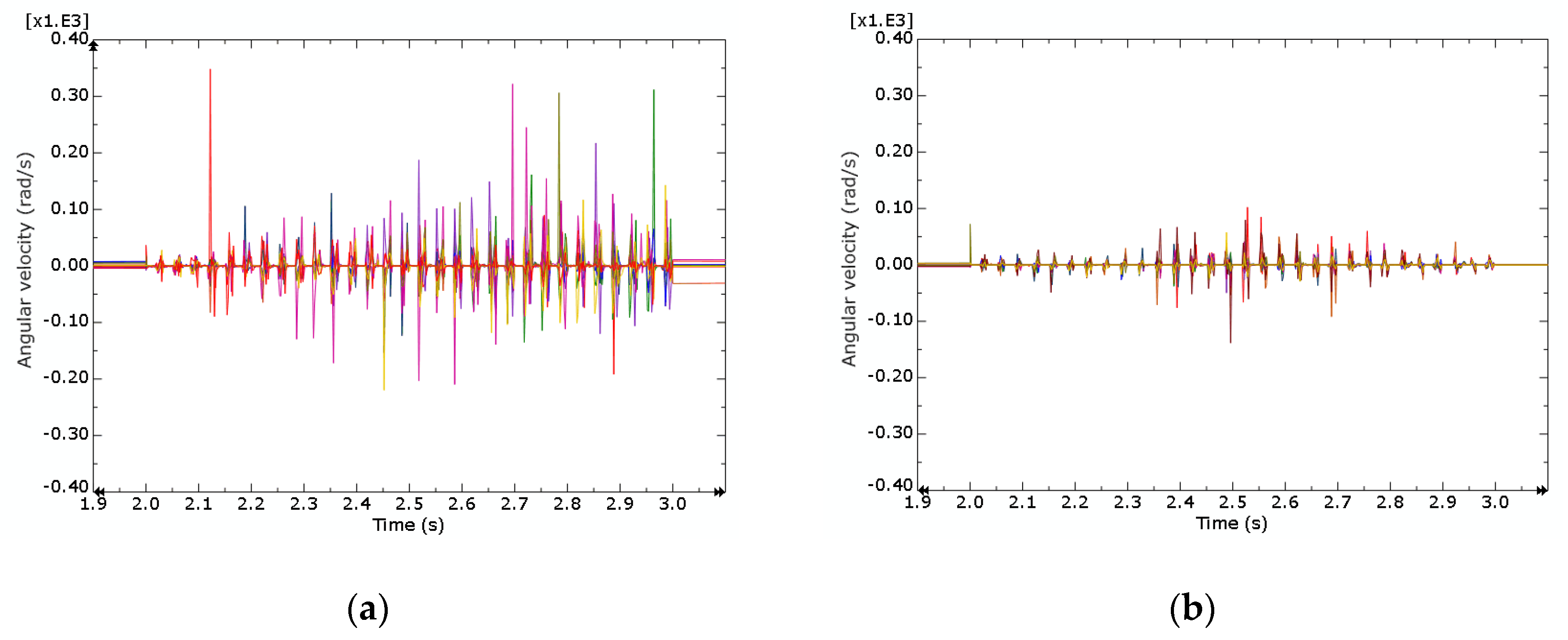
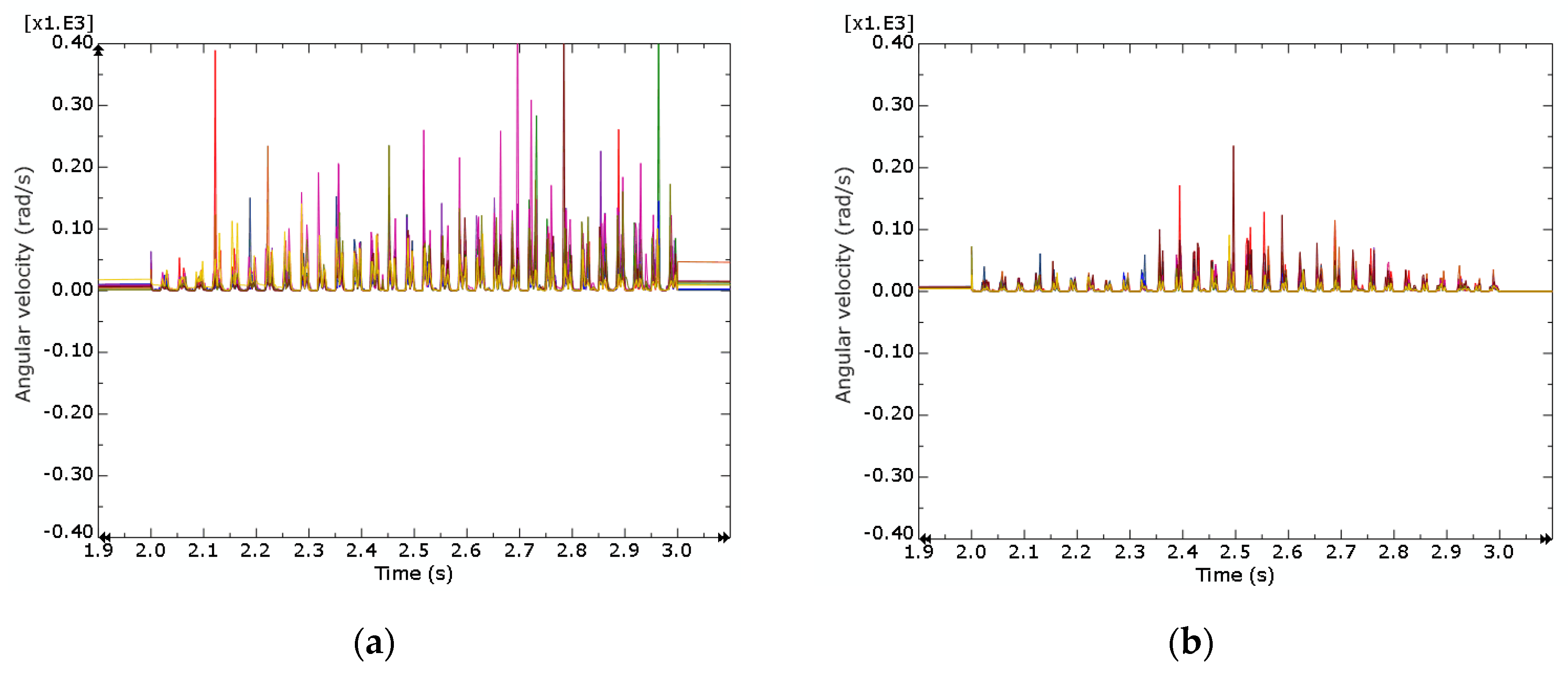
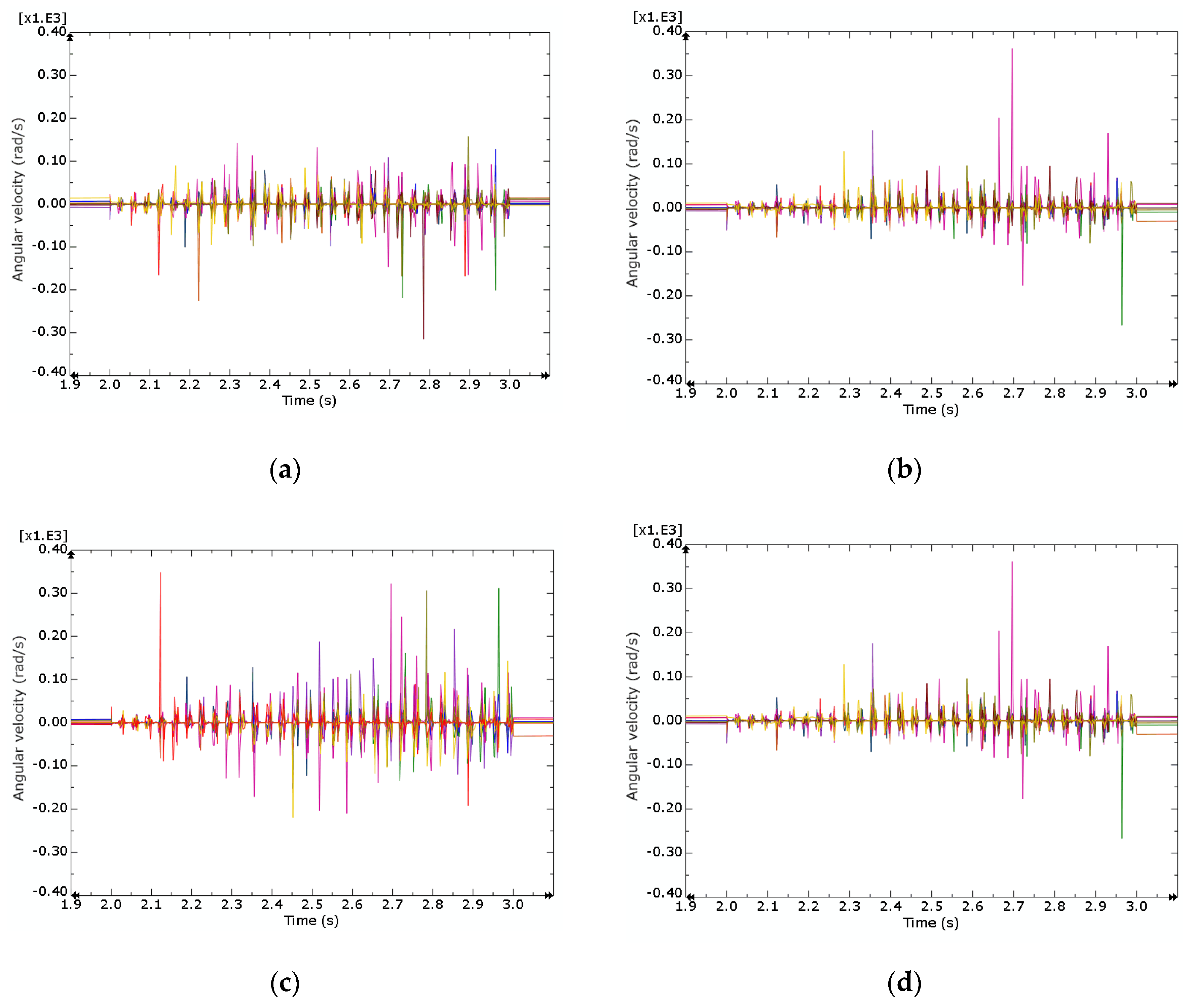
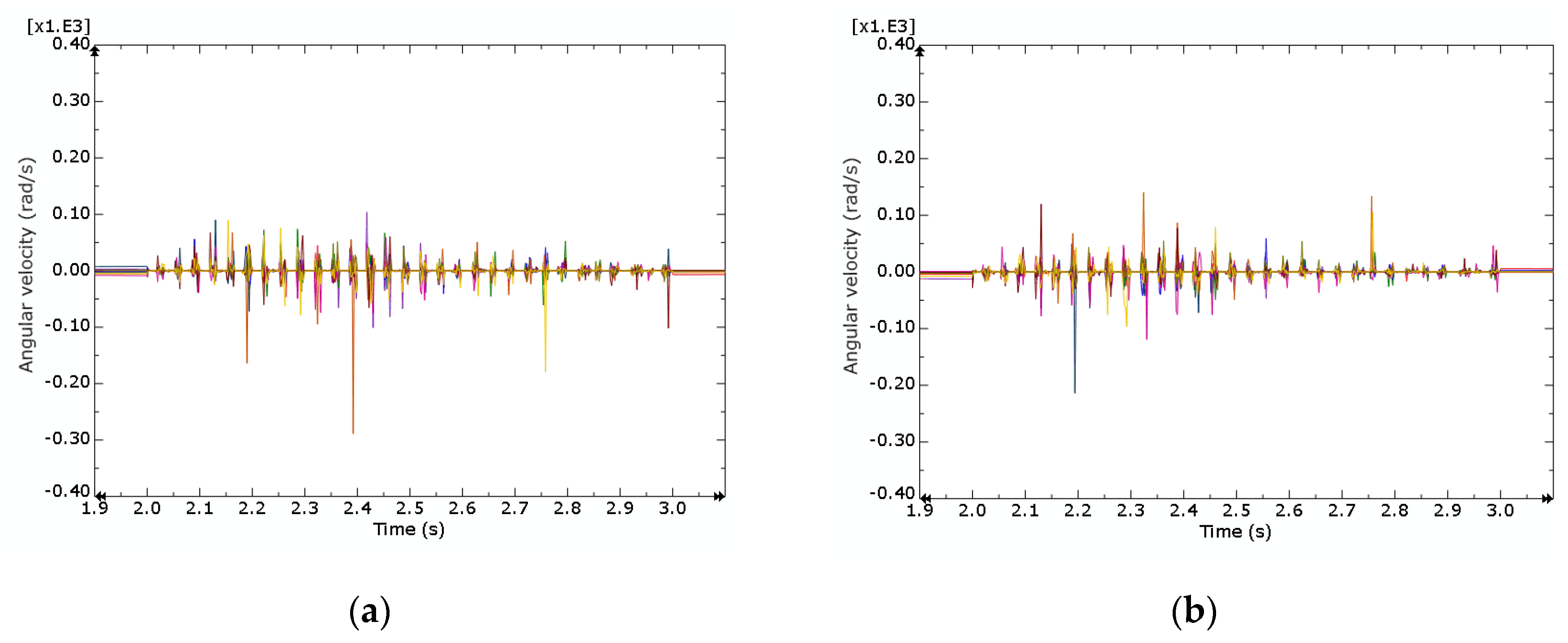
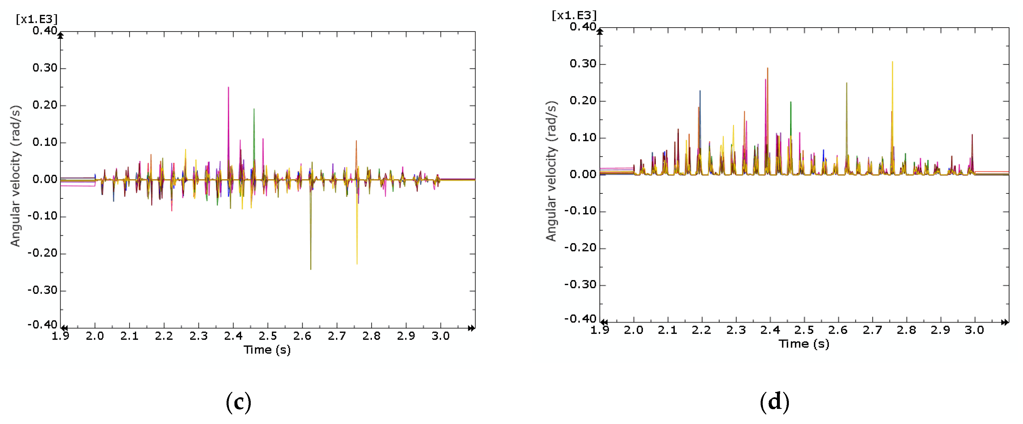
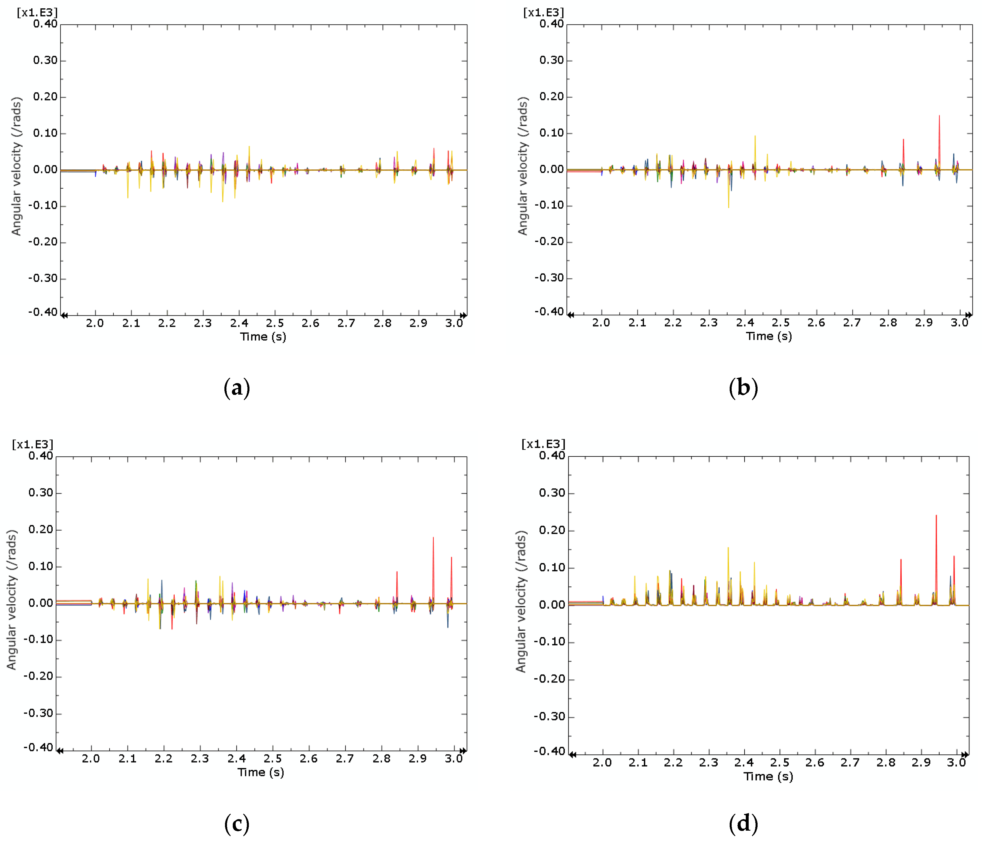
Compaction is a critical step in the building of asphalt pavement; the quality of the asphalt pavement plays a significant role; both under-compaction and over-compaction will have an impact on the quality of the asphalt pavement; and numerous variables influence asphalt compaction, including material-related characteristics such as the gradation of the asphalt mixture and paver-related parameters such as the paving speed, and others. This paper uses a coupled FEM-DEM method to simulate the preliminary compaction process, considering the influence of the gradation of the asphalt mixture and the paving speed on the preliminary compaction process. By observing the angular velocity of the particles, it was concluded that the graded asphalt mixture with AC 11 aggregate could be better compacted by the paver compared with the PA 11 mixture, and the paving speed could be controlled within a suitable speed range to achieve a better trade-off between paving quality and project efficiency.
As preliminary research on the FEM-DEM coupled method for simulating the compaction, the data obtained from the model may differ from the actual situation for several possible reasons. For example, in this model, the asphalt mixture was only compacted one time under the action of the paver, while it is better to have more than two times in real situation. Thus, the compaction has not yet reached the required level. Another limitation is that the actual aggregates are not represented in the ABAQUS program, but are instead uniformly substituted by spheres, which decreases the degree to which the simulation is accurate in comparison to the real scenario to some extent. To conduct simulations with acceptable accuracy and low computational cost, the approach to simplify the geometry of the aggregates while keep their main features will be used to simulate the aggregates [
30]. In addition, more factors, such as ambient temperature and wind velocity, are supposed to be considered in the simulation to get close to the real condition of pavement construction. Based on the information such as the characterization of aggregate skeleton derived from the preliminary compaction simulation, the final compaction by the roller compactor with finite deformation can be simulated by FEM, and the stability of the asphalt mixture can be predicted by the methodology proposed in [
31]. Moreover, more parameters used to evaluate compaction will be presented; for example, the porosity of the material or the apparent density, and the evenness of the pavement. The ultimate research aim is to develop a mature numerical model for simulating the compaction process which can be applied in Building Information Modeling and Digital Twin for road construction and maintenance.


 ,
, 


