
FRP Poles: A State-of-the-Art-Review of Manufacturing, Testing, and Modeling

 , , and
Abstract
:
1. Introduction
1.1. FRP Industry
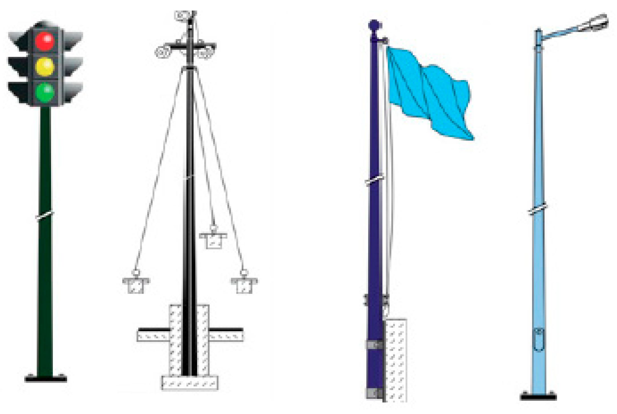
1.2. Poles
1.3. Research Objective
2. Methodology
2.1. Research Program
2.2. Research Organization
3. Material Properties
3.1. FRP Materials
3.2. Physical, Mechanical, and Chemical Properties
4. Manufacturing Techniques of FRP Poles
4.1. Filament Winding
4.2. Pultrusion
4.3. Centrifugal Casting
4.4. Hand Lay-Up
5. Testing of FRP Poles
5.1. Design Codes and Allowable Limits
5.2. Standard Test Procedures
5.3. Previous Experimental Research Program
6. Modeling of FRP Poles
6.1. Simple Linear Static Models
6.2. Advanced Static Models
6.3. Dynamic Modes
6.4. Fatigue/Fracture Mechanics/Cyclic Models
7. Discussion
7.1. Advantages and Disadvantages of FRP Types
7.2. Advantages and Dis-Advantages of FRP Manufacturing Techniques
7.3. Advantages and Disadvantages of FRP Modeling
8. Conclusions and Recommendations
- According to the comparison between the fiber-reinforced polymers poles manufacturing methods, the Pultrusion process was more accurate than others but more expensive. Therefore, the most suitable method was the centrifugal process due to its low cost.
- The analysis indicates major differences in stiffness and strength when comparing fiber-reinforced polymers poles to standard metallic poles.
- According to the different types of fibers, glass fiber was the best choice for Poles due to its low cost, UV resistance, electric insulation, and energy absorption.
- For the chosen sites, the pole load capabilities were determined to be between 0.95 and 1.48 times the design wind load. By increasing the footing dimension, the pole’s capacity increases.
- According to FE studies, the maximum moment of the GFRP pole increased significantly as the diameter or wall thickness of the pole was increased. Local buckling was the most common mode of failure for GFRP poles, but it may change to rupture in tension when the wall thickness is high.
- The FEM results for deflection and ultimate load of the specimens were very similar to the experimental results.
- Based on the results, the study concluded that the FEM could be used with trust in the research and design of GFRP structures such as utility poles and towers without the high cost of experimentation.
- Gap Studies:
- Recommendations for Future Work:
Author Contributions
Funding
Institutional Review Board Statement
Informed Consent Statement
Data Availability Statement
Acknowledgments
Conflicts of Interest
References
- Masuelli, M.A. Introduction of Fibre-Reinforced Polymers—Polymers and Composites: Concepts, Properties and Processes; IntechOpen: San Luis, Ergentina, 2013. [Google Scholar]
- Gerami, H. Development and Numerical Modeling of Composite Structures. Master’s Thesis, University of Manitoba, Winnipeg, MB, Canada, 2 September 2016. [Google Scholar]
- Economic Benefits of Increasing Electric Grid Resilience to Weather Outages; U.S. Department of Energy, U.S. Executive Office of the President: Washington, DC, USA, 2013.
- ANSI C136.20-1990; Fiber-Reinforced Plastic Lighting Poles. American National Standards Institute: Washington, DC, USA, 1990.
- Fouad, F.H.; Mullinax, E.C., Jr. FRC Poles for Distribution Power Lines. In Proceedings of the Advanced Technology in Structural Engineering, Philadelphia, PS, USA, 8–10 May 2000. [Google Scholar]
- Kim, S.H.; Kim, G.N.; Hong, S.J.; Kim, C.W.; Jang, W.S.; Yoon, S.J. Structural Behavior of FRP Lighting Pole System. Mater. Sci. Forum 2010, 654–656, 1034–1037. [Google Scholar] [CrossRef]
- Elhegazy, H. State-of-the-art review on benefits of applying value engineering for multi-story buildings. Intell. Build. Int. 2020, 1–20. [Google Scholar] [CrossRef]
- Elhegazy, H.; Eid, M.M. A state-of-the-art-review on grey water management: A survey from 2000 to 2020s. Water Sci. Technol. 2020, 82, 2786–2797. [Google Scholar] [CrossRef] [PubMed]
- Gudonis, E.; Timinskas, E.; Gribniak, V.; Kaklauskas, G.; Arnautov, A.K.; Tamulėnas, V. FRP Reinforcement for Concrete Structures: State-of-the-Art Review of Application and Design. Eng. Struct. Technol. 2013, 5, 147–158. [Google Scholar] [CrossRef] [Green Version]
- Castiglioni, C.A.; Maura, I. Experimental Results on Centrifugated GFRP Poles for Electric Lifelines. J. Compos. Constr. 1999, 3, 125–133. [Google Scholar] [CrossRef]
- Mitchell, J.R. Experimental and Numerical Investigations into Optimal Partial Concrete Filling of FRP and Steel Tubular Poles; Queen’s University: Kingston, ON, Canada, 2008. [Google Scholar]
- Yen, H.-C. Method of Manufacturing a Fiber Reinforced Plastic (FRP) Lighting Pole. U.S. Patent Application No. 20100148408A1, 17 December 2010. [Google Scholar]
- Polyzois, D.; Raftoyiannis, I.G.; Ibrahim, S. Finite elements method for the dynamic analysis of tapered composite poles. Compos. Struct. 1998, 43, 25–34. [Google Scholar] [CrossRef]
- Annual Book of ASTM Standards: 2001; American Society for Testing and Materials: West Conshohocken, PA, USA, 2001.
- RS Composite Utility Poles. Composite Poles for Electric Utility & Communication Applications. Available online: https://fdocuments.in/document/composite-poles-for-electric-utility-communication-poles-usa-technical.html?page=2 (accessed on 2 February 2022).
- Polyzois, D.; Ibrahim, S.; Raftoyiannis, I.G. Performance of fiber-reinforced plastic tapered poles under lateral loading. J. Compos. Mater. 1999, 33, 941–960. [Google Scholar] [CrossRef]
- Metiche, S.; Masmoudi, R. Analysis and Design Procedures for the Flexural Behavior of Glass Fiber-Reinforced Polymer Composite Poles. J. Compos. Mater. 2013, 47, 207–229. [Google Scholar] [CrossRef]
- Ridd, P.; Prudhon, E.; Saint-Gobain Reinforcements. GRC Poles Made by the Filament Winding Process. Available online: https://grca.org.uk/pdf/congress-2005/16%20-%20GRC%20POLES%20MADE%20BY%20THE%20FILAMENT%20WINDING%20PROCESS.pdf (accessed on 20 November 2021).
- Ibrahim, S.; Polyzois, D. Ovalization Analysis of Fiber-Reinforced Plastic Poles. Compos. Struct. 1999, 45, 7–12. [Google Scholar] [CrossRef]
- Ibrahim, S.; Polyzois, D.; Hassan, S.K. Development of glass fiber reinforced plastic poles for transmission and distribution lines. Can. J. Civ. Eng. 2000, 27, 850–858. [Google Scholar]
- Ibrahim, S.M. Performance Evaluation of Fiber-reinforced Polymer Poles for Transmission Lines. University of Manitoba. 2000. Available online: http://hdl.handle.net/1993/2237 (accessed on 5 February 2022).
- Jung, J.; Abolmaali, A.; Choi, Y. Finite-Element Analysis of Tapered Steel and Fiber-Reinforced Plastic Bridge Camera Poles. J. Bridge Eng. 2006, 11, 611–617. [Google Scholar] [CrossRef]
- Mitchell, J.; Fam, A. FRP Tubular Poles with Partial Concrete Filling. In Proceedings of the First Asia-Pacific Conference on FRP in Structures, Hong Kong, China, 12–14 December 2007. [Google Scholar]
- Salib, S.; Abdel-Sayed, G. Dynamic Behaviour and Seismic Response of FRP Light Poles in High Seismic Zones. In Proceedings of the 6th International Conference on FRP Composites in Civil Engineering, Rome, Italy, 13–15 June 2012. [Google Scholar]
- Metiche, S.; Masmoudi, R. Full-Scale Flexural Testing on Fiber-Reinforced Polymer (FRP) Poles. Open Civ. Eng. J. 2007, 107, 37–50. [Google Scholar]
- Torrán, E.A.; Zitto, S.; Cotrina, A.D.; Piter, J.C. Bending Strength and Stiffness of Poles of Argentinean Eucalyptus grandis. Maderas Cienc. Tecnol. 2009, 11, 71–84. [Google Scholar] [CrossRef] [Green Version]
- Mitchell, M.J.; Fam, A. Tests and Analysis of Cantilevered GFRP Tubular Poles with Partial Concrete Filling. J. Compos. Constr. 2010, 14, 115–124. [Google Scholar] [CrossRef]
- Broniewicz, M.; Broniewicz, F.; Broniewicz, E. A Full-Scale Experimental Investigation of Utility Poles Made of Glass Fibre Reinforced Polymer. Materials 2021, 14, 7398. [Google Scholar] [CrossRef]
- Zhang, L.L.; Sun, Q.; Zhang, L. Experimental Study on the Durability of Glass Fiber Reinforced Polymer Pole and Tower for Power Transmission. Adv. Mater. Res. 2010, 168–170, 1717–1724. [Google Scholar] [CrossRef]
- Ramirez-Vazquez, I.; Hernández-Corona, R.; Salgado-Talavera, J.E. Composite Materials as an Alternative to Replace Steel Members on Lattice Power Transmission Towers. J. Mater. Civ. Eng. Am. Soc. Civ. Eng. 2015, 28, 04015151. [Google Scholar]
- Balagopal, R.; Prasad Rao, N.; Rokade, R.P. Simplified Model to Predict Deflection and Natural Frequency of Steel Pole Structures. J. Inst. Eng. India Ser. A 2018, 99, 505–607. [Google Scholar] [CrossRef] [Green Version]
- Marzuki, H.F.A.; Jaafar, M. Laminate Design of Lightweight Glass Fiber Reinforced Epoxy Composite for Electrical Transmission Structure. Procedia Chem. 2016, 19, 871–878. [Google Scholar] [CrossRef]
- Xiao, K.; Hu, Q.; Xie, W. The Stress Analysis and Calculation Method of the Poles of Different Arrangement Styles in the Distribution Network Lines and the Research of “Abandoning Wires to Protect Electric Poles” Project. In Proceedings of the 3rd International Conference on Mechatronics and Information Technology, Shenzhen, China, 9–10 April 2016. [Google Scholar]
- Urgessa, G.; Mohamadi, S. Structural Assessment of Fiber-reinforced Polymer Composite Electric Poles. Procedia Eng. 2016, 145, 707–714. [Google Scholar] [CrossRef] [Green Version]
- Vivek, B.; Sharma, S.; Raychowdhury, P.; Ray-Chaudhri, S. A study on failure mechanism of self-supported electric poles through full-scale field testing. Eng. Fail. Anal. 2017, 77, 102–117. [Google Scholar] [CrossRef]
- Tripathi, S.; Gupta, S.; Kumar, V.; Tiwari, P. Hybrid Utility Poles and their application in Power System: Refinement in Construction and Design of Conventional Utility Pole. In Proceedings of the 2020 International Conference on Electrical and Electronics Engineering (ICE3), Gorakhpur, India, 14–15 February 2020. [Google Scholar]
- Almutairi, A.D.; Bai, Y.; Wang, Y.; Jeske, J. Mechanical performance of fibre reinforced polymer confined softwood timber for pole applications. Compos. Struct. 2020, 235, 111807. [Google Scholar] [CrossRef]
- Siringoringo, D.M.; Fujino, Y.; Nagasaki, A.; Matsubara, T. Seismic performance evaluation of existing light poles on elevated highway bridges. Struct. Infrastruct. Eng. 2020, 17, 649–663. [Google Scholar] [CrossRef]
- Alshurafa, S.; Alnaafa, M.A.; Polyzois, D. Development of GFRP Guyed Communication Towers. In Proceedings of the International Conference on Fibre-Reinforced Polymer (FRP) Composites in Civil Engineering, Istanbul, Turkey, 8–10 December 2021. [Google Scholar]
- Si, J.; Qiu, S.; Feng, S.; Chen, J.; Wang, Z. Experimental study on axial compression buckling of glass fiber reinforced plastics solid pole with circular cross-section. Adv. Struct. Eng. 2022, 913–924. [Google Scholar] [CrossRef]
- Masmoudi, R.; Mohamed, H.; Metiche, S. Finite Element Modeling for Deflection and Bending Responses of GFRP Poles. J. Reinf. Plast. Compos. 2008, 27, 639–658. [Google Scholar] [CrossRef]
- Chaithra Fousi, M.S. An Investigation of Wind Load Effect on a Light Pole Structure with Stiffener Using. ANSYS Int. J. Adv. Eng. Res. Dev. 2017, 4, 453–494. [Google Scholar]
- Fam, A.; Son, J.K. Finite element modeling of hollow and concrete-filled fiber composite tubes in flexure: Optimization of partial filling and a design method for poles. Eng. Struct. 2008, 30, 2667–2676. [Google Scholar] [CrossRef]
- Saboori, B.; Khalili, S.M.R. Static analysis of tapered FRP transmission poles using finite element method. Finite Elem. Anal. Des. 2011, 47, 247–255. [Google Scholar] [CrossRef]
- Mohamadi, S. Finite Element Analysis of Fiber-reinforced Polymer Composite Electric Poles. Ph.D. Thesis, George Mason University, Fairfax County, VA, USA, 2017. [Google Scholar]
- Mohamed, H.M. Finite Element Modeling of CFRP Composite Pole Structures. Int. J. Eng. Appl. Sci. Technol. 2021, 42, 1543–1564. [Google Scholar]
- Ricardo dos Santos, P.; Cimini, C.A. Numerical Analysis of GFRP Poles. In Proceedings of the 24th ABCM International Congress of Mechanical Engineering, Curitiba, Brazil, 3–8 December 2017. [Google Scholar]
- Abdelkarim, O.I.; Guerrero, J.M.; Mohamed, H.M.; Benmokrane, B. Behaviour of Pultruded Glass Fibre-Reinforced Polymer Utility Poles Under Lateral Loads. In Proceedings of the CSCE Annual Conference, Laval, PQ, Canada, 12–15 June 2019. [Google Scholar]
- Altanopoulos, T.I.; Raftoyiannis, I.G.; Polyzois, D. Finite element method for the static behavior of tapered poles made of glass fiber reinforced polymer. Mech. Adv. Mater. Struct. 2020, 28, 2141–2150. [Google Scholar] [CrossRef]
- Je-Kuk Son, A.F. Finite element modeling of hollow and concrete-filled fiber composite tubes in flexure: Model development, verification and investigation of tube parameters. Eng. Struct. 2008, 30, 2656–2666. [Google Scholar]
- Pal, U.; Mukhopadhyay, G.; Kumar, B.N.; Bhattacharyya, S. Electric pole failure: A safety concern. Eng. Fail. Anal. 2019, 103, 249–258. [Google Scholar] [CrossRef]
- Mohamed, H.; Masmoudi, R. Design Optimization of GFRP Pole Structures Using Finite Element Analysis. In Proceedings of the American Composites Manufacturers Association, Tampa, FL, USA, 15–17 January 2009. [Google Scholar]
- Polyzois, D.; Raftoyiannis, I.G.; Philopulos, D. An Experimental Survey of the Static and Dynamic Behavior of Jointed Composite GFRP Tapered Poles. Mech. Adv. Mater. Struct. 2007, 14, 203–212. [Google Scholar] [CrossRef]
- Khalili, S.M.R.; Saboori, B. Transient dynamic analysis of tapered FRP composite transmission poles using finite element method. Compos. Struct. 2010, 92, 275–283. [Google Scholar] [CrossRef]
- Alshurafa, S.; Alhayek, H.; Polyzois, D. Finite element method for the static and dynamic analysis of FRP guyed tower. J. Comput. Des. Eng. 2019, 6, 436–446. [Google Scholar] [CrossRef]
- Fam, A.; Kim, Y.J.; Son, J.K. A numerical investigation into the response of free end tubular composite poles subjected to axial and lateral loads. Thin-Walled Struct. 2010, 48, 650–659. [Google Scholar] [CrossRef]
- Noh, J.; Ghadimi, B.; Russo, S.; Rosano, M. Assessment of FRP pultruded elements under static and dynamic loads. Compos. Struct. 2017, 202, 17–28. [Google Scholar]


| FRP Type | Tensile Strength (GPa) | Density (t/m3) | Modulus of Elasticity (GPa) | Shear Modulus (GPa) | Poisson’s Ratio |
|---|---|---|---|---|---|
| Electrical-resistant E-glass | 3.4 | 2.5 | 40 | 30 | 0.22 |
| High-strength S-glass | 4.5 | 2.5 | 56 | 35 | 0.22 |
| Carbon | 2.5–4 | 1.7 | 150 | 20 | 0.20 |
| Carbon (high-modulus) | 4.8 | 1.9 | 200 | 23 | 0.20 |
| Carbon (high-strength) | 2.7 | 1.7 | 300 | 27 | 0.20 |
| Aramid | 3.4 | 1.4 | 62 | 21 | 0.35 |
| Technique | Manufacturing Process |
|---|---|
| Centrifugal Process | Fiber roving Rolling Sheets Rotating Die Resin injection |
| Pultrusion Process | Fibers rolls Resin Heated Die Puling Device Cut-off |
| Filament Winding Process | Creel Continuous roving Resin bath Rotating Mandrel |
| Hand Lay-up Process | Contact Mold Laminate Resin Reinforcement |
| Code | Deflection under Max Wind Conditions | Deflection under Static Conditions | Load Point from Top (m) |
|---|---|---|---|
| ASTM | Not exceed 15% pole height | Not exceed 1% pole height | 0.30 |
| CSA | Not exceed 20% pole height | Not exceed 1% pole height | 0.25 |
| AASHTO | Not exceed 15% pole height | Not exceed 1% pole height | 0.30 |
| Working Load Applied (kg) | 25 | 50 | 75 | 100 | 125 | 150 | 175 | 200 |
|---|---|---|---|---|---|---|---|---|
| GRC pole Sample average–Deflection % | 0.4 | 0.7 | 1.1 | 1.4 | 1.8 | 2.2 | 2.6 | 3.1 |
| FRP pole Sample average–Deflection % | 2.1 | 3.6 | 5.2 | 6.8 | 8.4 | 10 | 11.4 | 13.1 |
| Length | 10,000 mm |
| Support | 1524 mm |
| Diameter | Bottom 270 mm Top 114 mm |
| Weight | 580 N |
| Strength | 4638 N |
| Density | 1800 kg/m3 |
| Breaking load | 2930 N |
| Material | Stress (MPa) | Deformation (mm) |
|---|---|---|
| Circular FRP pole | 16 | 98 |
| Hexagonal FRP pole | 19 | 124 |
| Methods | Advantages | Disadvantages |
|---|---|---|
| Filament Winding |
|
|
| Pultrusion |
|
|
| Centrifugal Casting |
|
|
| Hand Lay-up |
|
|
| Model | Advantages | Disadvantages |
|---|---|---|
| Linear Static | The solving process is relatively short compared to a nonlinear analysis on the same model. The maximum discrepancy of the maximum stress for the typical FRP pole concerning the ANSYS model was almost 10%. | Applicable only to structural problems where stresses remain in the linear elastic range of the used material. |
| Advanced Static | The program accounts for the nonlinear behavior of the poles and gives a good prediction for the ultimate load at failure. | Nonlinear effects can originate from geometrical nonlinearity (large deformations), material nonlinearity (elastoplastic material), and contact. |
| Dynamic | used to select more efficient cross sections for the compressive elements of the structure. It can be more critical than static loading for sheet pile members. | Numerical analysis is required to design the FRP columns with thin-walled parts. |
| Fatigue | The downwards and upwards reversal of load direction in each cycle did not significantly change the overall behavior when compared with a solely downwards loading. | The deflections increase with the number of cycles, but most of this increase occurred within the first 50,000 cycles. |
| Authors and Year | Description and Contribution of the Research | Gaps |
|---|---|---|
| [20] | On full-scale poles, twelve bending tests were performed up to failure. The number of layers and fiber orientation were among the test parameters. The current findings show that the established theoretical model can accurately predict the ultimate capacity and behavior of GFRP poles. | Study the stacking sequence of the fibers among the test parameters. |
| [17] | Composite materials’ permissible stress design theory under various stress states was employed to improve the available design techniques for fiber-reinforced polymer poles. The influence of these holes on the rapid reduction in the cross-sectional region of the poles was ignored by most design recommendations, which instead account for the effect of these holes on the abrupt decrease in the cross-sectional part of the poles. The accuracy of the established design techniques and current design approaches was confirmed compared to published test findings from the authors’ early experimental program. | Study the effect of the surface texture of the opening hole on the strength of FRP poles due to the stress concentration of this region. |
| [48] | Under lateral load, a full-scale GFRP distribution pole was tested until it failed. The pole in issue stood 10.5 m high, had a diameter of 254 mm, and a wall thickness of 6.35 mm. With increasing the diameter or wall thickness of the GFRP pole, the maximum moment increased significantly. Local buckling was the most common mode of failure for GFRP poles | Study the effect of the pole fixation method on the maximum moment. |
| [49] | As cantilever beams, two poles made of glass-fiber-reinforced polymer were loaded to failure (NTUA). The experimental poles were created using the filament winding process. The experimental results comprised load-deflection data at the loading point and strain distribution at the fixed support. | Compare the results of load-deflection among different pole manufacturing techniques. |
Publisher’s Note: MDPI stays neutral with regard to jurisdictional claims in published maps and institutional affiliations. |
© 2022 by the authors. Licensee MDPI, Basel, Switzerland. This article is an open access article distributed under the terms and conditions of the Creative Commons Attribution (CC BY) license (https://creativecommons.org/licenses/by/4.0/).
Share and Cite
EL-Fiky, A.M.; Awad, Y.A.; Elhegazy, H.M.; Hasan, M.G.; Abdel-Latif, I.; Ebid, A.M.; Khalaf, M.A. FRP Poles: A State-of-the-Art-Review of Manufacturing, Testing, and Modeling. Buildings 2022, 12, 1085. https://doi.org/10.3390/buildings12081085
EL-Fiky AM, Awad YA, Elhegazy HM, Hasan MG, Abdel-Latif I, Ebid AM, Khalaf MA. FRP Poles: A State-of-the-Art-Review of Manufacturing, Testing, and Modeling. Buildings. 2022; 12(8):1085. https://doi.org/10.3390/buildings12081085
Chicago/Turabian StyleEL-Fiky, Ahmed M., Youssef Ahmed Awad, Hosam Mostafa Elhegazy, Mahmoud Galal Hasan, Ibrahim Abdel-Latif, Ahmed M. Ebid, and Mohamed A. Khalaf. 2022. "FRP Poles: A State-of-the-Art-Review of Manufacturing, Testing, and Modeling" Buildings 12, no. 8: 1085. https://doi.org/10.3390/buildings12081085