Article

Investigating the Impact of Inclusions on the Behavior of 3D-Printed Composite Sandwich Beams

1
Mechanical Engineering Department, UAE University, Al Ain 15551, United Arab Emirates
2
Engineering Requirements Unit, UAE University, Al Ain 15551, United Arab Emirates
3
Civil and Environmental Engineering Department, UAE University, Al Ain 15551, United Arab Emirates
*
Author to whom correspondence should be addressed.
Buildings 2022, 12(9), 1448; https://doi.org/10.3390/buildings12091448
Submission received: 22 July 2022 / Revised: 2 September 2022 / Accepted: 6 September 2022 / Published: 14 September 2022
(This article belongs to the Section Building Structures)

Abstract

:
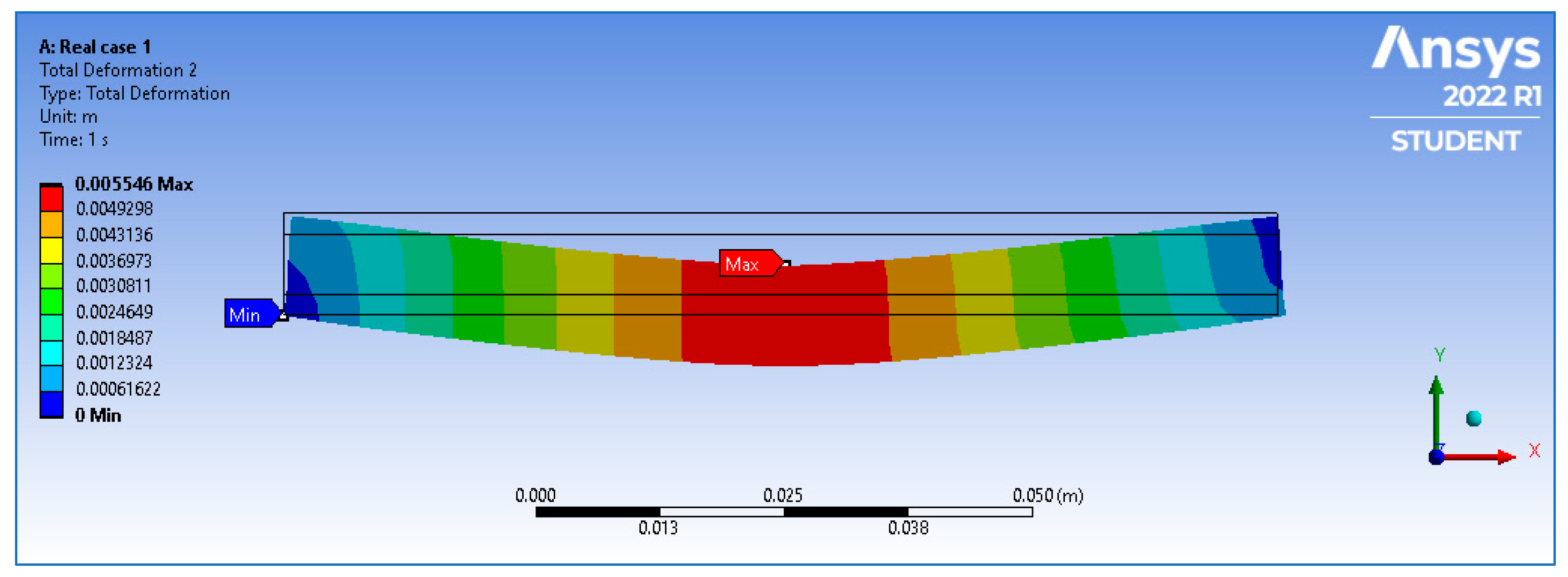
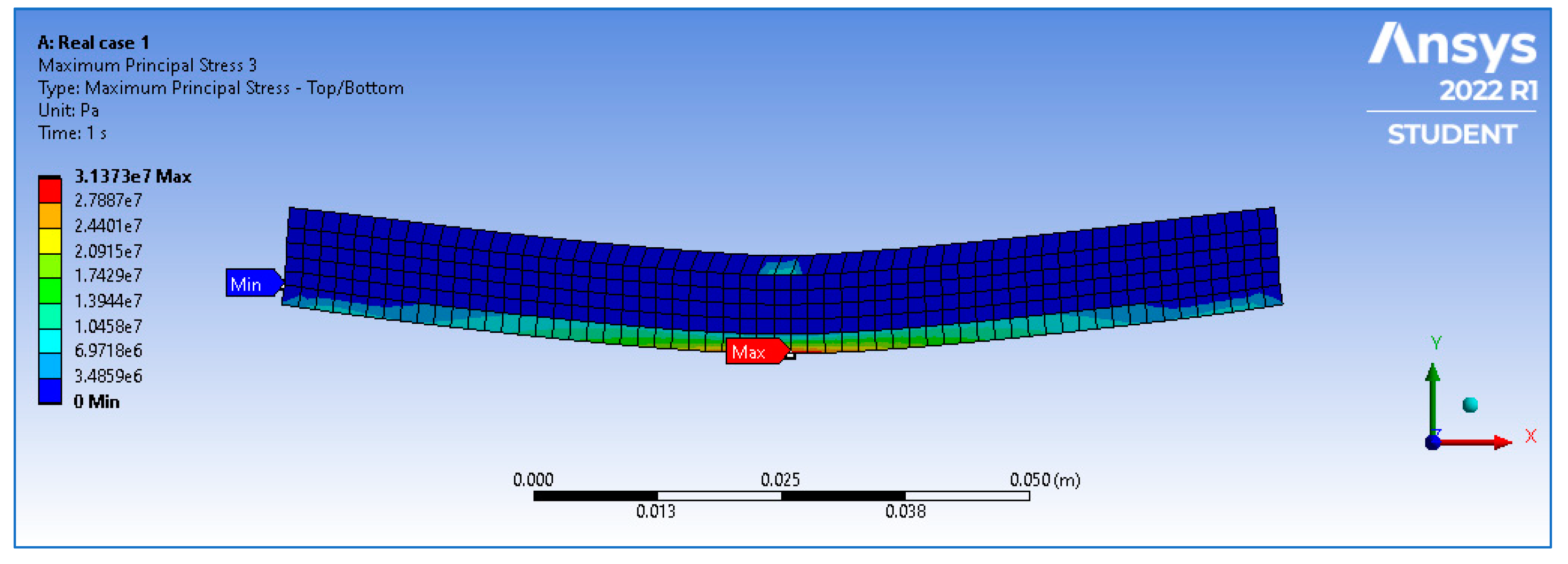
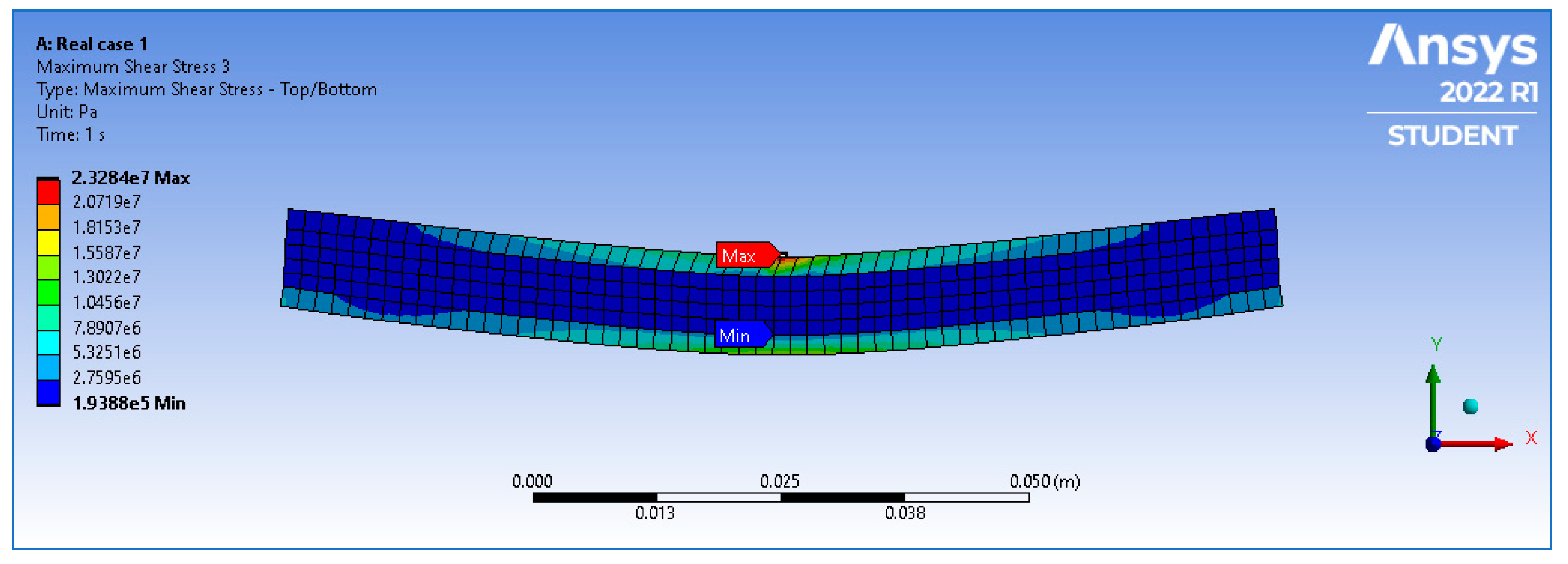
In this study, a finite element model was developed, and a detailed analysis was carried out to investigate the impact of inclusions on the mechanical characteristics of a 3D-printed composite sandwich beam that could initiate when printing the layers, especially during the transition period between the dissimilar material that would affect the interfacial strength between the layers that would cause the failure of the 3D-printed beams. Several parameters that could influence the failure mechanism have been investigated. These parameters include the location, size, material properties, and interfacial location of the inclusion along the beam. Linear elastic behavior has been adopted in this finite element analysis using the ‘Ansys’ simulation tool to model and analyze the defective beams compared to the intact ones. The effects of defects related to maximum shear stress (MSS) and maximum principal stress (MAPS) were investigated. The results revealed that the midpoint of the composite is highly stressed (31.373 MPa), and the concentration of stress decreases outward as we move toward the edges of the composite to reach zero at the edges. For the intact case, the deformation was maximum at the center of the composite (4.9298 mm) and zero at both ends of the beam. The MSS was highest at the center (23.284 MPa) and decreased gradually as we approached the ends on both sides to reach 0.19388 MPa at the edges, making the shear stress distribution symmetrical. The MAPS is constant throughout the beam apart from the lower face of the beam and is maximum at the face material. The MSS is high at the endpoints where we have the support reactions, which may weaken the entire material’s mechanical properties. It was also observed that along the load L3 (applied at 2 mm from the top face of the beam), the MSS values decrease as we move away from the center, which may cause failure at the end of the beam. It was also noticed that the presence of inclusions along load L2 (applied at 2 mm from the bottom face of the beam) initially causes a sharp decrease in MAPS while moving away from the center, at 25 mm, while the MAPS increases as it approaches the end of the beam. This increase in the MAPS near the beam support might be due to the reaction of the fixed support, which tends to oppose the applied flexural load and hence increases the principal stress capability of the beam.

1. Introduction

Additive manufacturing (AM), also defined as the Rapid Prototyping Technique, is a relatively new manufacturing technique comprising a variety of layered manufacturing processes that can help quickly produce complex geometries [1]. The evolution of modern digital AM technology has unfolded a new era of material production, which offers immense flexibility in creating a range of end-consumer products and multifunctional material systems [2,3,4,5]. AM helps make various usable products using materials (polymers, ceramics, metals, composites) and techniques. Over time, AM has gained vital importance in manufacturing spacecraft parts [6,7], aircraft components [8,9], consumer products [10], and medical accessories [11,12]. Among the range of AM techniques, 3D printing is arguably one of the most versatile techniques, which produces parts via Fused Filament Fabrication (FFF) or Fused Deposition Modeling (FDM) [13].
Sandwich composite structures have gained the attention of researchers since the 1980s [14] and gained more attention and popularity in modern-day industries (i.e., aircraft and airspace), mainly due to their isotropic properties and improved characteristics [15,16]. In sandwich composites, a second phase fiber or particulate (core) is induced in-between the primary material (face skin) to enhance the mechanical properties of the final composite. The two thin face skin sheets are usually made of a stiff, dense, high Young’s modulus and relatively strong material compared to a lightweight, thick core [17]. The face skin material possesses higher tensile and compressive strength, while the lightweight core exhibits shear stiffness [16]. The composition offers a unique combination of desirable properties: the stiffer and high-strength skin provides protection from impact loads and protects the structure during compressive and tensile loadings. The lightweight core helps reduce the overall weight and increases the shear strength of the sandwich composites. A schematic of a typical sandwich composite is shown in Figure 1 [18].
The conventional method of producing composite sandwich beams includes producing skin material and core separately and bonding the same afterwards via a complicated and costly bonding process [19,20,21]. Three-dimensional printing technology is feasible for obtaining complex sandwich composites in a single piece, but it can also be used to develop a correlation between composite attributes and required functional properties [22]. Three-dimensional printers can be utilized to create customized products based on CAD/CAM data [23]. The process does not only help in producing complex products with almost negligible material wastage, but it also ensures cost efficiency.
Research on scrutinizing 3D-printing process parameters and their effect on the end-product quality and mechanical behavior has been growing since its inception. However, these studies can be divided into a few core directions: numerical analysis and testing of core structures, thermal and viscous–elastic flow patterns, mechanical behavior, and skin and core material properties evaluation. The sandwich composites manufactured via 3D printing have extensively been studied for their energy absorption capabilities [24], compression strength [25], and shape recovery effect of 3D-printed structures [26]. The outcome of these studies proved the mechanical efficiency of end products and 3D printing process viability for manufacturing sandwich and honeycomb structures that can be used in various industries ranging from aerospace to transport, medical to architecture, and so on [27,28]. However, it is worth mentioning that the 3D-printing process still faces scientific challenges that must be scrutinized to enhance the mechanical behavior of 3D-printed sandwich composites.
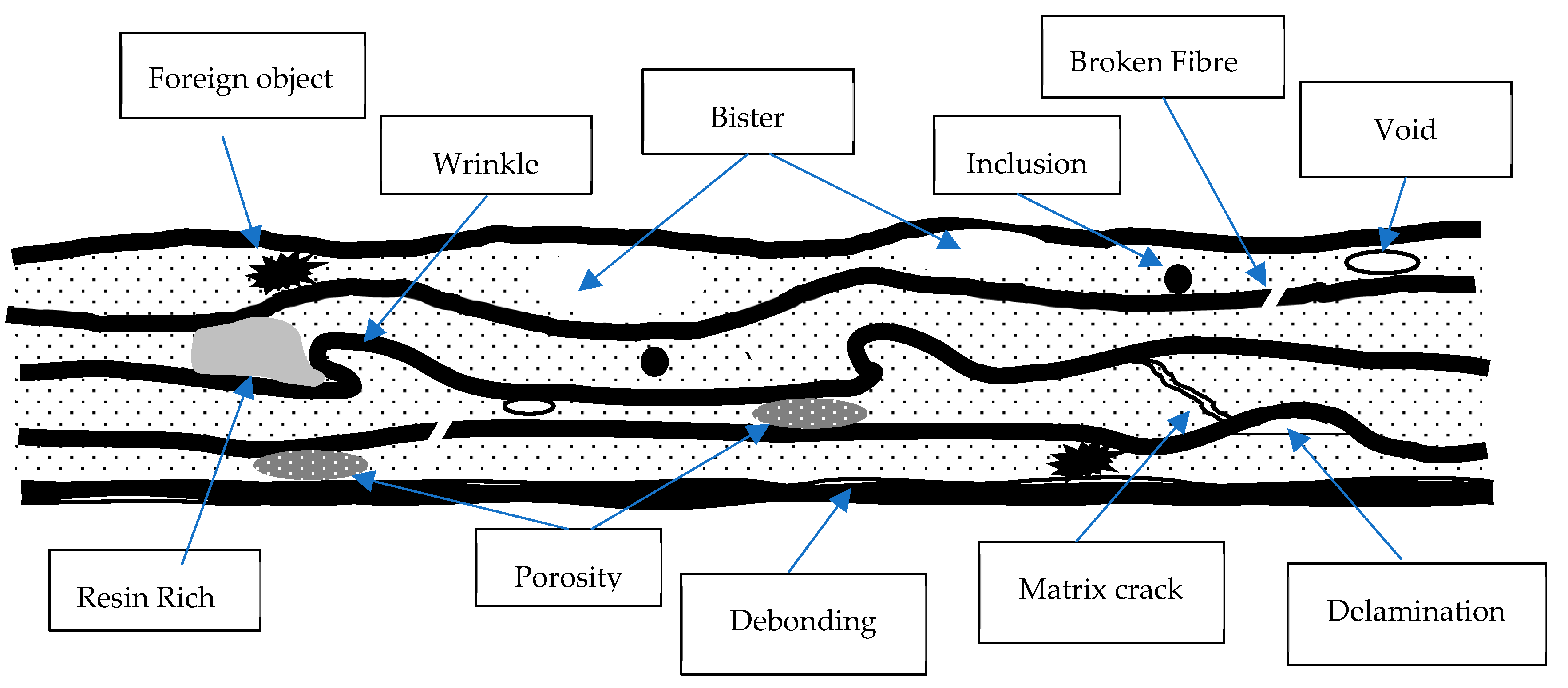
The thermal nature and viscous–elastic flow involved during the 3D-printing process induce heterogeneities, such as air bubbles, inclusions, defects, pores, etc., in the final product, which significantly affect the mechanical properties of the end product [29,30,31,32]. Some of the major defects that can be formed in sandwich composites include porosity, delamination, and crushed cores: (i) in porosity, defect clusters of several air bubbles get entrapped in laminates due to the presence of gas, which ultimately damages the surface topography of composite, (ii) delamination refers to the formation of cracks in the skin structure due to impact load or shear strength with an ability to propagate and affect the structural strength of the sandwich composites, and (iii) in crushed cores, as the name suggests, the core is compressed in one or more cells, which damage that whole structure [33]. The most common defects found in composites are shown in Figure 2 [34]. The impact of prestressing by using Fe-based memory alloy bars on the bending behavior of reinforced concrete beam was examined numerically. For this purpose, the Finite Element Analysis approach was used for numerical evaluation of the bending response of concrete beam including nonlinear material [35].
In light of the above literature, it is evident that the technology to manufacture sandwich composites using 3D printing is still evolving. The process includes multiple hurdles in overcoming its defects, which ultimately affect the end-product quality. Thus, the characterization of these defects can help improve the end-product quality. A correlation between inclusion size, position, material type, and its effect on the mechanical behavior of the end product needs to be inspected for a sound understanding of the process. The observation of moment redistribution behavior occurring because of flexural and shear loading in glass fiber-reinforced polymer and reinforced continuous concrete beam was conducted using the FEA approach [36]. The Artificial Neural Network (ANNs) was used to examine and predict the structural responses of externally bonded FRP regarding how it strengthens RC T-beam under combined torsion and shear effect. In addition, the structural performance of RC T-beam is higher than RC rectangular beam in structural analysis and design [37].
This study is carried out to fill the gap and find answers to some basic questions related to inclusion defects in the 3D printing of sandwich composite beams and to examine the impact of these defects on the mechanical behavior of end composites. The defect location, geometry, and material (Young’s modulus) have been varied, along with the meeting profiles of the face and core materials. The effect of these defects-related parameters on maximum shear stress (MSS), maximum principal stress (MAPS), and equivalent stress (ES) are studied using the Ansys simulation tool. The analysis has been carried out such that at a time, only one defect parameter is changed, and its impact is observed while keeping the rest of the properties unchanged. In particular, the behavior of 3D-printed sandwich composites and the effect of inclusion properties on mechanical behavior under bending load is explored using numerical simulations. The constant bending load is subjected to the symmetrical center of the beam for all the cases using roller support at one end and a triangular one on the other end. These findings help explore the effect of inclusion on the mechanical behavior of sandwich beams and correlate its mechanical responses by varying location, geometry, and material properties of the inclusion.
The importance and novelty of this study is in its use of the 3D printing AM technique to produce sandwich composites that have isotropic properties and improved characteristics and mechanical properties in the final composite. The two thin face skin sheets of the composites are relatively strong compared to the lightweight thick core, as they possess higher tensile and compressive strength, while the lightweight core exhibits shear stiffness. The composition is stiffer with high strength and, as such, offers a unique combination of desirable properties, provides protection from impact loads, and protects the structure during compressive and tensile loadings. The lightweight core, on the other hand, helps reduce the overall weight and increases the shear strength of the sandwich composites.
In this study, an intensive finite element analysis was carried out to investigate the impact of inclusions on the mechanical characteristics of a 3D-printed multimaterial sandwich beam that could initiate whenever printing the layers, especially during the transition period between the dissimilar material that would affect the interfacial strength between the layers that would cause the failure of the 3D-printed beams. Many parameters that could influence the failure mechanism have been studied, such as the location of the inclusion along the beam, size, properties, and interfacial area. Linear elastic behavior has been adopted in this analysis to model and analyze the defective beams compared to the intact ones.

2. Material Properties and Experimental Setup

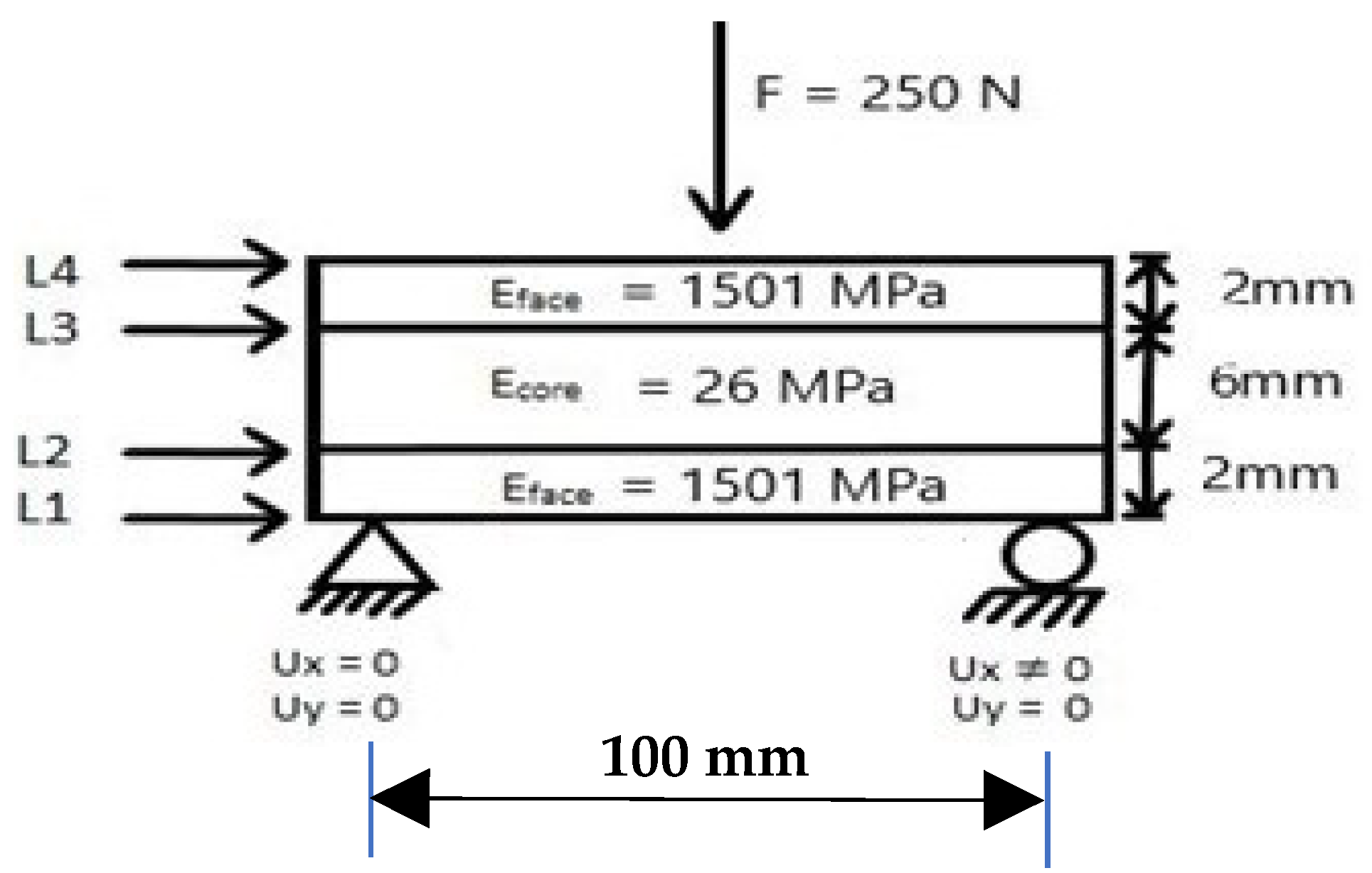
In this study, FEA of the sandwich, molded via 3D printing using two different materials, was performed. The upper and lower face of the sandwich is of the same material having an elastic modulus of (Eface) 1501 MPa. On the other hand, a high-flexible material has been selected as the core of the sandwich to ensure high flexibility. The elastic modulus of the sandwich core (Ecore) is 26 MPa. The properties of the material used in the study for the TPU core [38] and glass fiber composite for the upper and lower surfaces of the sandwich [39] are based on experimental testing data supplied by the filaments producer that are tested according to international standards. Some of the essential material properties of the face and core materials are given in Table 1.
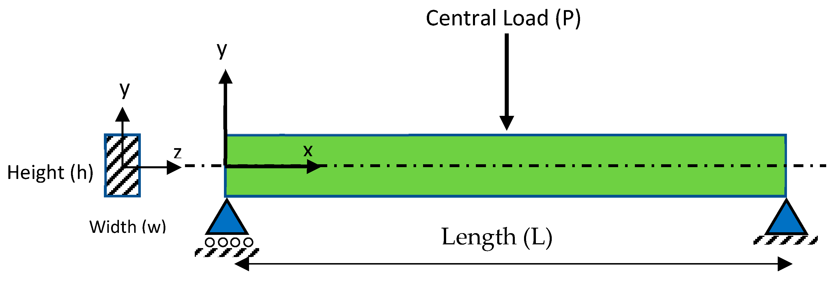
An experiment was carried out by subjecting the composite sandwich beam shown in Figure 3 to a bending load (F) of 250 N. The load applied on the sandwich beam was at the midspan of the beam’s length. The beam is supported on the left end by a triangular fixture with Ux = 0 and Uy = 0 boundary conditions, while the right end of the beam is supported by a roller fixture with Ux ≠ 0 and Uy = 0 boundary conditions. As shown in Figure 3, loads L3 and L2 depict the upper and lower joining profile/layer of the face and core materials, respectively. The thickness of the upper and lower face material is kept as 2 mm each with a 6 mm core. The length of the beam is 100 mm, while its width is maintained at 20 mm.

3. Research Methodology

Initially, a finite element model was developed for the case considered in this study, and then a finite element analysis (FEA) of the defect-free intact composite sandwich beam was carried out. A simplified multilayer sandwich beam model has been adopted as well as elastic shear and peels stresses in an adhesive joint between the faces [40,41]. Linear elastic properties have been considered in the FEA [42] since the engineering components are designed with the elastic zone that simplifies the handling of complicated cases. It has been proven experimentally and theoretically that a unique, high-flexible sandwich panel could be produced from stiff faces such as glass fiber-reinforced composite with an elastic core such as TPU using 3D-printing technology (FDM) that shows a superior elastic behavior [43].
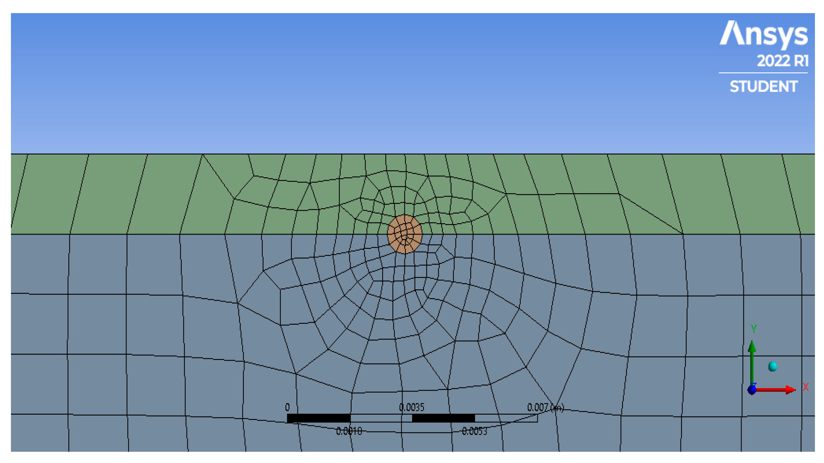
The effect of bending load is explored using ‘Ansys R1’ software. Once the mechanical properties of the defects-free sandwich beam, under bending load, are achieved, the FEA of inclusion (defects) sandwich beam is carried out. The number of nodes and elements for the inclusion case was kept as 591 and 525, respectively. The number of nodes and elements was kept as 420 and 354, respectively. The face mesh schematic of the defect case is shown in Figure 4. The effect of inclusion position, geometry (radius), and Young’s modulus (E) on maximum principal stress (MAPS), maximum shear stress (MSS), and equivalent stress (ES) of the composite sandwich along L3 and L2 are examined. The Young’s modulus of face and core materials remains unchanged at 1501 MPa and 26 MPa, respectively. Table 2 depicts the range of each operating parameter of inclusion and its corresponding notation, designs of experiments (DoEs), and the group division of experiments for which the related mechanical properties of the composite sandwich are explored.
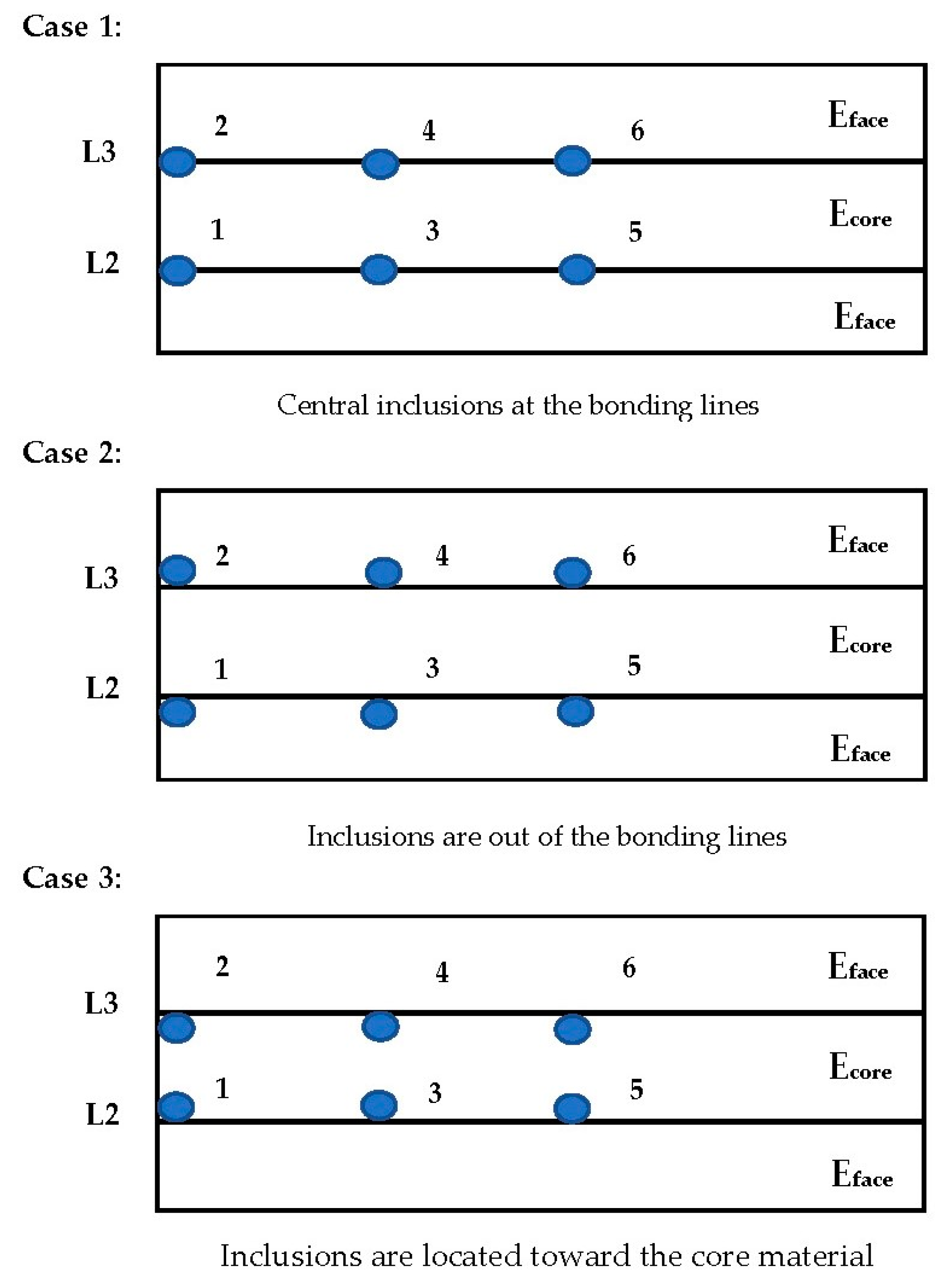
The analysis has been divided into 3 cases depending on the placement of inclusion with respect to the face and core materials of the composite sandwich, as shown in Figure 5. The circles depict the inclusion along L2 and L3. C1, C3, and C5 are placed along the horizontal axis on L2 at a distance of 0 mm, 25 mm, and 50 mm from the left edge, respectively. Similarly, C2, C4, and C6 are placed along the horizontal axis on L3 at a distance of 0 mm, 25 mm, and 50 mm from the left edge, respectively. C1 and C2 represent inclusion in semicircular geometry, while the geometry of the rest of the defects is entirely circular.
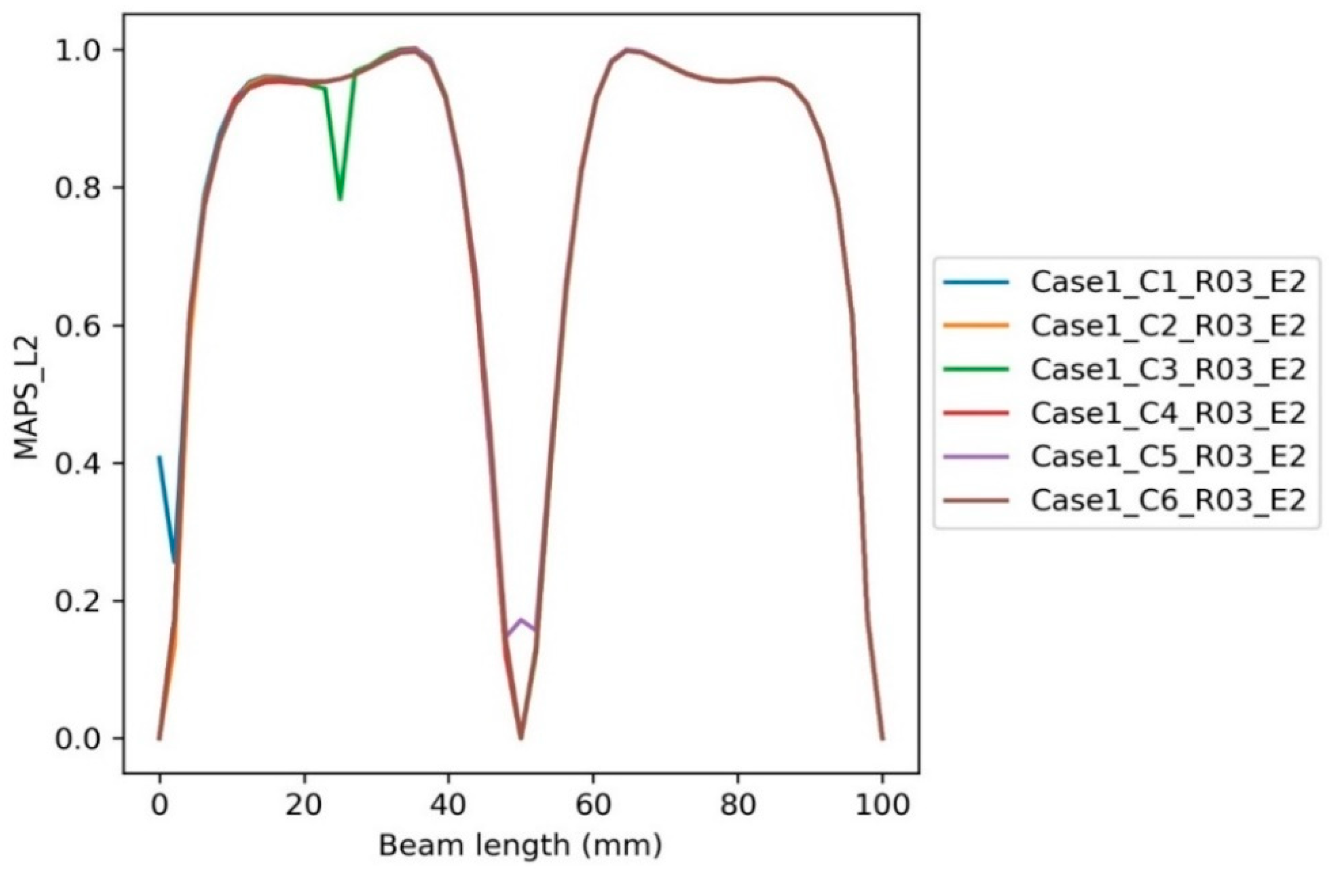
The nomenclature used in this study for each analysis is shown in a way where the first subscript indicates the case number, the second depicts the circle number (position), the third subscript defines the radius of inclusion (geometry), and the fourth subscript specifies the Young’s modulus of inclusion. For example, Case 1_C1_R03_E2 depicts case number 1, circle 1 (0 mm on L2), with a radius of 0.3 mm and a Young’s modulus of 26 MPa.

4. FDM 3D Printing for the Manufacturing of Multilayered Bi-Materials

The 3D-printing process is not informal to control because numerous factors affect the quality and properties of the finished part when dealing with two different materials, mainly when the same manufacturer does not utilize the filament used in the 3D-printing process [44]. Additionally, the open source slicing software has numerous restrictions, which added other factors leading to more complexity in the production of bi-material 3D-printing products, specifically when the 3D printer was not designed to handle this task. On the other hand, the dual-core 3D-printing system is mainly designed in order to have one nozzle for the predominance material. In addition, the different nozzle is primarily used to sustain filament and for multiextrusion 3D printing. Furthermore, it is designed faster to eliminate by breaking away from the 3D-printed product and leaving a smooth finish product which affords an excellent adhesion to the mail filament as an inexpensive solution. This kind of material is generally made of biodegradable material.
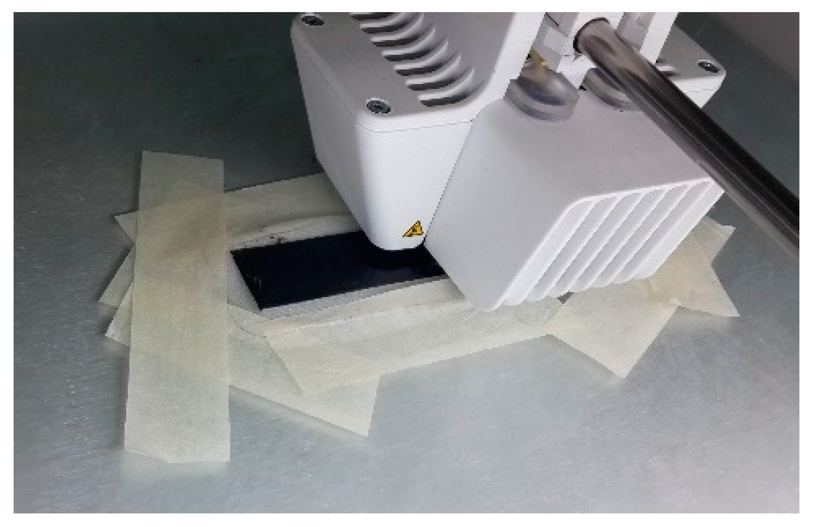
One of the significant challenges faced in this research is dealing with bed temperature [45], which would impact the adhesion characteristics of the raft layer of the 3D-printed parts, and sometimes this needs many trials until reaching the right bed temperature, especially when dealing with an open-source 3D-printer [46]. Some other factors that may influence the process are the ambient temperature, humidity, adhesive utilization over the bed, printing speed and nozzle diameter, calibration and clearance between the bed and the nozzles, and cooling process [47]. Figure 6 describes the support layer’s resonating failure when printing the sandwich beam’s glass fiber layer. Unluckily, making the bundle of layers, which was TPU 95A, is not applicable since the layer will not be stiff enough to tolerate the glass fiber layer because of the low-elastic modulus of the more significant flexible material layer and high deformation. Paper tape may be used to overcome this problem when this kind of problem happens in short beams [48].
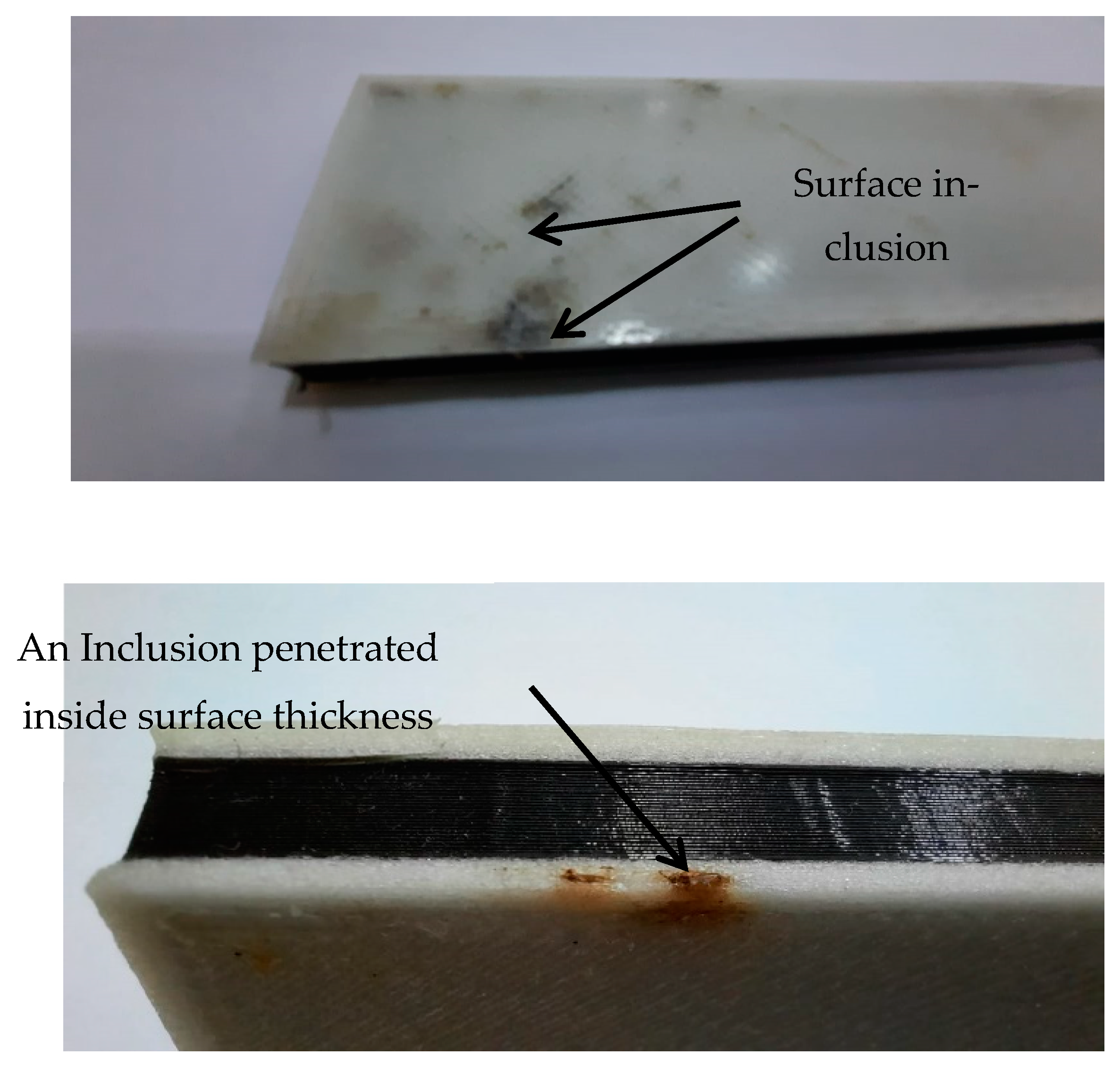
In an attempt to overcome the peal problem, multiple parts were printed simultaneously, as shown in Figure 7. It was examined that the clangor problem had vanished. Still, unluckily, because of the long standby time of the second nozzle (TPU 95A core head), numerous droplets of high-elastic material were printing the glass fiber layers. Since there is no locking on the nozzle head to resist the highly flexible material from falling because of the gravity force, this kind of issue may be caused by inclusion, such as defects that will affect the adhesion characteristics between the stacked layers of the sandwich and eventually affect the mechanical properties [49]. Various approaches were adopted in order to reduce the high-elastic material droplet over the printed parts, such as by cleaning the surface when printing through pausing, and this caused other issues, such as the addition of time waste and the inconsistency in the printing parameters, or by covering the nozzle with a small number of droplets. Eventually, a complete product can be obtained, but at least the droplet existed at the last printed layer, as shown in Figure 8.

5. Analytics for a Beam under Bending Load

The flexural rigidity EI is generally involved in beams with various geometrical characteristics brought on by various stiffening capabilities. A thorough analysis of the load-deflection performance within the elastic zone is therefore required, and analysis of the flexural stiffness, which directly affects the rigidity of the beam subjected to bending loads, would be possible [50,51]. In order to identify the beam stiffener with the best flexural characteristics given the geometrical properties of the beam, the comparison of the performance of the load-deflection variables is made. The following Equation describes the curvature of an Euler–Bernoulli beam under a pure bending moment M brought on by the center load P [52,53]:
2 v x 2 = M E I
Small beams can obtain a closed-form solution by integrating Equation (1) and considering the proper boundary conditions [54]. Figure 9 illustrates a beam supported by a bending load, where:
M: Bending moment
V(x): Elastic curve
I: Moment of inertia in the Z-direction
h: Beam height
L: The length of the beam
EI: Flexural rigidity
The maximum deflection occurs at the midspan of the beam at the position of the bending force, which can be described by [55]:
δ = | 1 48 E I P L 3 |
δ : Maximum Deflection
P = Central Load
L = Length of the Beam
The Euler–Bernoulli Equation (Equation (2)) is used for specified force values and deflection to determine the beam’s central deflection under a central concentrated load. To determine the flexural rigidity, Equation (2) can be modified. Equation (3) depicts the flexure strain as a function of the maximum deformation which the beam induced by stress–strain correlation for uniaxial loading condition, length of the beam, and thickness of the beam:
ϵ = 6 δ h L 2
ϵ : Flexure strain
h : Thickness of the beam
When the applied force is at a specific distance (c) from the neutral axis of the beam, the bending stress is given by the following Equation [56]:
σ = M c I
σ : Bending Stress
M = Moment
c = Distance from the neutral axis
Linear elasticity-based displacements can be used to express the equilibrium of 3D objects using the following Equation [57]:
μ 2 u + ( λ + μ ) ( · u ) + P = 0
u : displacement, P : body force, λ : Lamé’s constant, μ : shear modulus
As indicated in Equation (5), u and P represent the displacement and body force vectors in the Cartesian coordinate system. The following Equation introduces μ and λ as the shear modulus and Lamé’s constant, respectively, using the modulus of elasticity E and the Poisson’s ratio ν:
μ = E 2 ( 1 + ν ) ,   λ = E ν ( 1 + ν ) ( 1 2 ν )
E : modulus of elasticity, ν : Poisson’s ratio
When the body’s own weight is ignored, Equation (7)’s y-direction equilibrium equation changes to is the reduced shape to be:
μ 2 ν + ( λ + μ ) y ( · u ) = 0
Additionally, the displacement formulation needs to be compatible. Equation (7) presents displacement formulas that can be solved using a variety of possible functions of displacement [58]. Here is an illustration of the Euler–Bernoulli time-dependent equation for beam bending in the y-axis direction: [51]
ρ A 2 ν t 2 + 2 M z x 2 = f y
ρ : density, M z : moment around the z-axis, f y : force per unit length in the y-axis
In Equation (8), a cross-section “ρ” stands for density, “Mz” for a moment around the z-axis, and “fy” for a force per unit length on the y-axis. The force-deflection behaviors of the beams are connected to these geometrical characteristics. The behavior of force deflection is lesser for the beam with a more considerable flexural rigidity and higher for the beam with a smaller flexural rigidity. As a result, the force-deflection measurements in the linear sections are to determine the flexure rigidity of the 3D-printed 3D models, which cannot be calculated hypothetically.
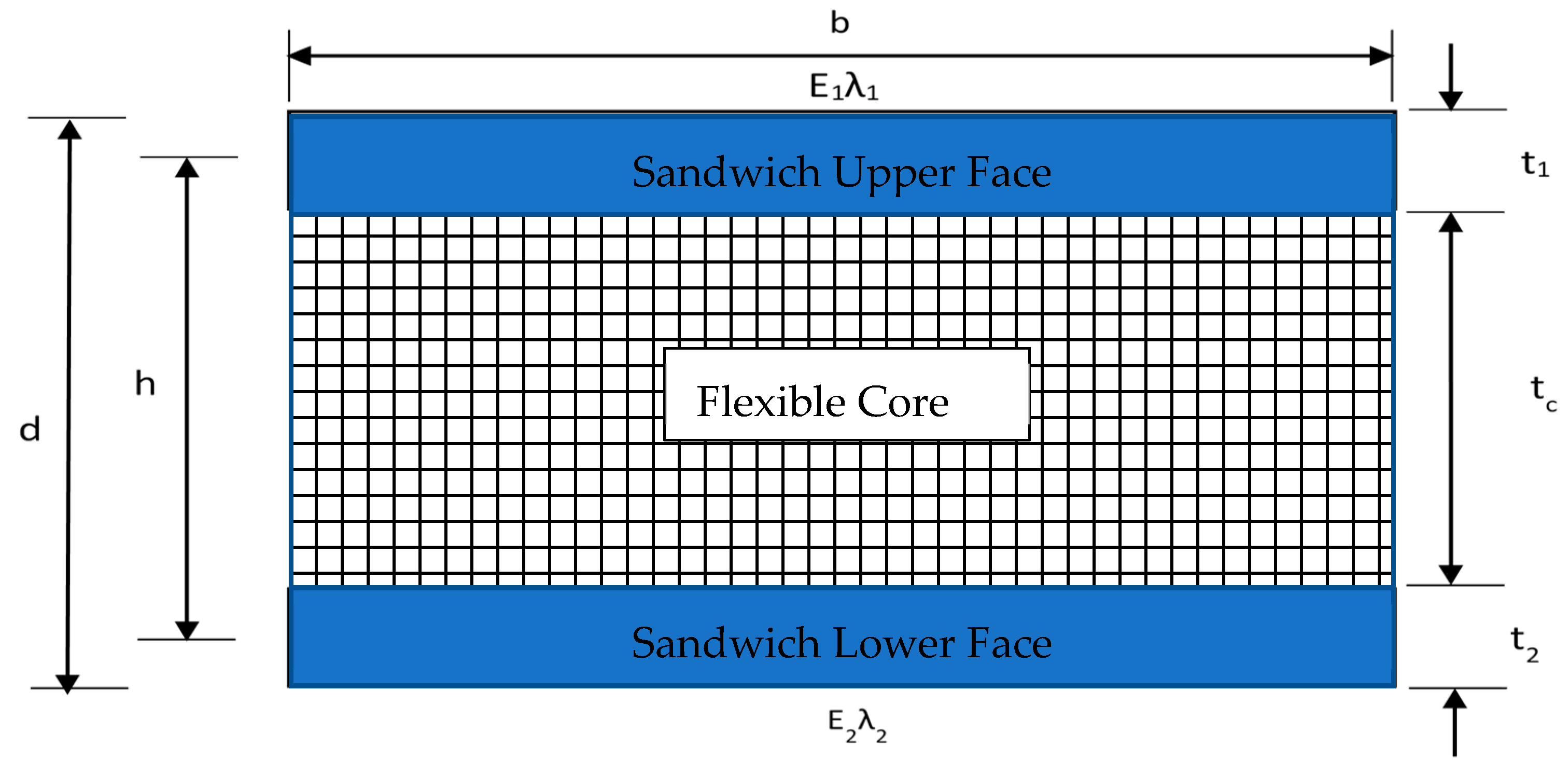
In this study, the typical formulas for sandwich honeycomb panels will be first described, and then the precise solution will be presented [59]. The panel’s nomenclature is displayed in Figure 10, where “b” stands for the sandwich panel, “d” for the sandwich panel’s thickness, “E” for the facing modulus, “E’c” is the core bending modulus (assumed to be 0), “h” is the length from the center of the top to the center of the bottom, “t” is the thickness, “λ” is equal to 1-µxµy (µ is the Poisson’s ratio and subscripts x and y are allocated for the directions), “τc” is the shear stress of the core, and “σf” is the bending stress. It is worth mentioning that the top and bottom facings are indicated by subscripts 1 and 2, respectively, while the core is characterized by subscript c. If both facings are identical, then t1 = t2 = tf, E1 = E2 = Ef, and λ1 = λ2 = λf.
Figure 11 is used to determine the stresses on the facings. The standard or approximation assumes that the facing bears the entire bending load under the action of compressive and tensile forces substituted at a specific distance (h), separately, which is also the distance between the skin centroids. Additionally, it is expected that this force causes a uniform distribution of stress across the thickness of the facings.
The panel’s shear rigidity and bending stiffness can be used to compute the overall deflection. In the formulas used to obtain the standard bending stiffness (D) and rigidity (U), the facing moment of inertia (Io) and the core bending modulus (E′c) are taken to be equal to zero. The moment of inertia can be estimated by: Io = btf3/12. Since the tf value for thin facings is so low, using zero as a value has little chance of producing appreciable errors. Assuming that I = Io (neglected) + Ad2 = 0, E′c = 0, and b = 1, the approximate bending stiffness (D) is calculated using the following equations [58]:
D = E 1 t 1 E 2 t 2 h 2 E 1 t 1 λ 2 + E 1 t 1 λ 1
where:
D : Bending stiffness
E 1 : Sandwich upper face elastic modulus
E 2 : Sandwich lower face elastic modulus
t 1 : Sandwich upper face thickness
t 2 : Sandwich lower face thickness
λ 1 : Lamé’s constant of Sandwich upper face
λ 2 : Lamé’s constant of Sandwich lower face
h: Length from the center of the top to the center of the bottom
In relation to sandwich panels with identical-material facings [58]:
D = E f t 1 t 2 h 2 ( t 1 + t 2 ) λ f
For sandwich panels with identical-thickness and identical-material facings [58]:
D = E f t f h 2 2 λ f
However, the exact formulas to calculate the bending stiffness (D) are much more complex. These exact formulas are as follows [59]:
Exact bending stiffness:
D = 1 ( E 1 t 1 λ 1 ) + ( E c t c λ c ) + ( E 2 t 2 λ 2 )   [ E 1 t 1 E 2 t 2 h 2 λ 1 λ 2 + E 1 t 1 E c t c λ 1 λ c ( t 1 + t c 2 ) 2 + E 2 t 2 E c t c λ 2 λ c ( t 2 + t c 2 ) 2 ] + 1 12 [ E 1 t 1 3 λ 1 + E c t c 3 λ c + E 2 t 2 3 λ 2 ]
E c : Core bending modulus
λ c : Lamé’s constant of the core material
t c Thickness of the core material
For the sandwich kind of panels with facing the similar thickness and the similar material:
D = E t h 2 2 λ + 1 12 [ 2 E t 3 λ + E c t c 3 λ c ]
The “λf” is a term that appears in the bending stiffness equation. It has been reported that this value, 1-µxµy, has values of 0.98 for fiberglass, 0.91 for steel, and 0.89 for aluminum. Instead of narrow beams, this phrase should only be applied to sandwich panels that serve as plates. A wide beam deflects more forcefully than a narrow beam due to the Poison’s ratio effect. It is difficult to say when a beam begins to behave like a plate. However, it may be said that if the width of the beam is seven times more than its thickness value and more excellent than 1/3 of its span, it acts like a plate. The above derivations are used to present and simplify the mathematical model of a sandwich beam that is used to validate the experimental results through FEA.

6. Results and Discussion

This section presents the results of the intact case and the inclusion cases. In the intact case, an intact composite sandwich beam was subjected to a point load at the middle of the upper face and the maximum principal stress (MAPS) and maximum shear stress (MSS) values were recorded using the Ansys simulation tool. In the inclusion cases, the effect of varying inclusion positions on the MSS and MAPS values along various layers of the beam is explored. The following subsections present the details of these cases.

6.1. The Intact Case

In this study, the intact composite sandwich standard beam was subjected to a point load of 250 N at the middle of the upper face using the Ansys simulation tool, as shown in Figure 12. The beam is subjected to vertical load and tends to produce a concave-upward curved deformation. The simulation result of the deformation is shown in Figure 12. It is clear from the figure that the deformation is maximum at the center (at 50 mm from both ends) and minimum at the supports. The moment arm is maximum at the center of the beam, with respect to the end supports, thus inducing maximum deformation.
Examining the deflected shape shown in Figure 12, it can be observed that, under the given loading condition, the longitudinal elements above the center line undergo compression. At the same time, the lower portion exhibits tension along the x-axis. Thus, the beam confirms the simultaneous existence of both tensile and compressive stresses, also known as flexural stresses. The MAPS, along the length of the beam, induced due to vertical point loading on the beam, as shown in Figure 13. The MAPS is constant throughout the beam except on the lower face of the beam. The face material is experiencing maximum principal stress along the x-direction in the lower face compression region, indicating that the face material is strong in compression and weak in tensile loading. The MAPS distribution indicates that the beam exhibits minimum principal stress under a given loading, i.e., zero MPa in the beam’s upper face and core materials. Additionally, the stress is zero at the transition between tensile and compressive regions, known as the beam’s neutral axis [59].
Figure 14 depicts MSS distribution along the length of the beam under the given point loading. Unlike MAPS, the MSS distribution value is higher in the face material’s upper and lower regions and lower in the rest of the areas. It can be observed from Figure 14 that the MSS value is highest at the center of the beam and decreases gradually as we move away from the center of the beam on both sides. This might be due to the concentrated effect of the applied load at the center of the beam, which produces maximum shearing in that region compared to the rest of the areas.
The MSS value at the center of the upper face region is the highest, indicating that the face material exhibits maximum shear stress in the compression region. It can be extracted from Figure 14 that the shear stress is almost minimal near the supports, which further validates that the shear stress fades out as we move away from the point of impact. Furthermore, the decrease in shear stress near the ends of the beam can be attributed to the counter-reactive forces of beam supports that tend to neutralize the impact of the applied bending load [60].
In general, the FEA that was carried out using ANSYS software was performed using a smart auto mesh option to optimize the mesh size according to the geometry of the sandwich panel investigated for being both intact and defective. For the intact beam, the number of elements and nodes were 354 and 420, respectively, with a mesh size 1.7 mm. So, in order to stand on the impact of the FE mesh on the results achieved and analyzed in the study, the size of the standard elements that were used in the smart meshing was reduced to half one time (i.e., 0.85 mm), with 1298 elements and 1428 nodes, and reduced to the quarter on the other time (i.e., 0.425 mm), with 5664 elements and 5925 nodes.
The stresses along the critical interfacial bonding lines between the dissimilar materials are investigated and compared (i.e., L2 and L3), as shown in Figure 15. It has been observed that stresses along L2 show that maximum shear stresses (MSS) are higher than the smart mesh at 10% and 20% for the half and quarter mesh, respectively, which is the same trend found for the von Mises stresses (VM), whereas the maximum principal stresses demonstrated 10% and 40% higher than smart mesh for the half and quarter mesh. On the other hand, the max shear stresses along L3 illustrated that stresses are higher than the smart mesh with 10% and 30% for the half and quarter mesh, respectively, whereas the maximum principal stresses showed 30% and 50% higher stresses, but with 30% and 40% for the von Mises stresses (VM). This concludes that finer mesh is supposed to be used in analyzing the cases with inclusion in order to achieve accurate results. More mesh refinements have been considered to attain reliable, repeated, and consistent results that could be achieved with a mesh size of one-eighth of the smart meshing option that is reflected positively in minimizing the error to less than 0.01% by using a number of elements and nodes equal to 61 times and 53 times the smart mesh option, respectively.
The intact sandwich beam has been tested experimentally by a three-points bending test and compared theoretically and by FEA, as shown in Figure 16. It has been shown that the theoretical stiffness demonstrated a higher value than FEA, and the experimental work which explains that the FEA is more accurate than the mathematical model is derived from solid mechanics. Furthermore, the observed behavior of the sandwich beam shows a relatively close stiffness to the FEA results to some extent; then, it becomes nonlinear, approaching the max applied load. This behavior reflects the actual deformation of the 3D-printed sandwich beam because the core is made of flexible material, and the beam’s surfaces are made of stiff composite material. So, it is concluded that the current linear FEA is sufficient for the linear behavior of the sandwich beam since the designers use a safety factor to be within the elastic zone, away from the nonlinearity.

6.2. The Inclusion Cases

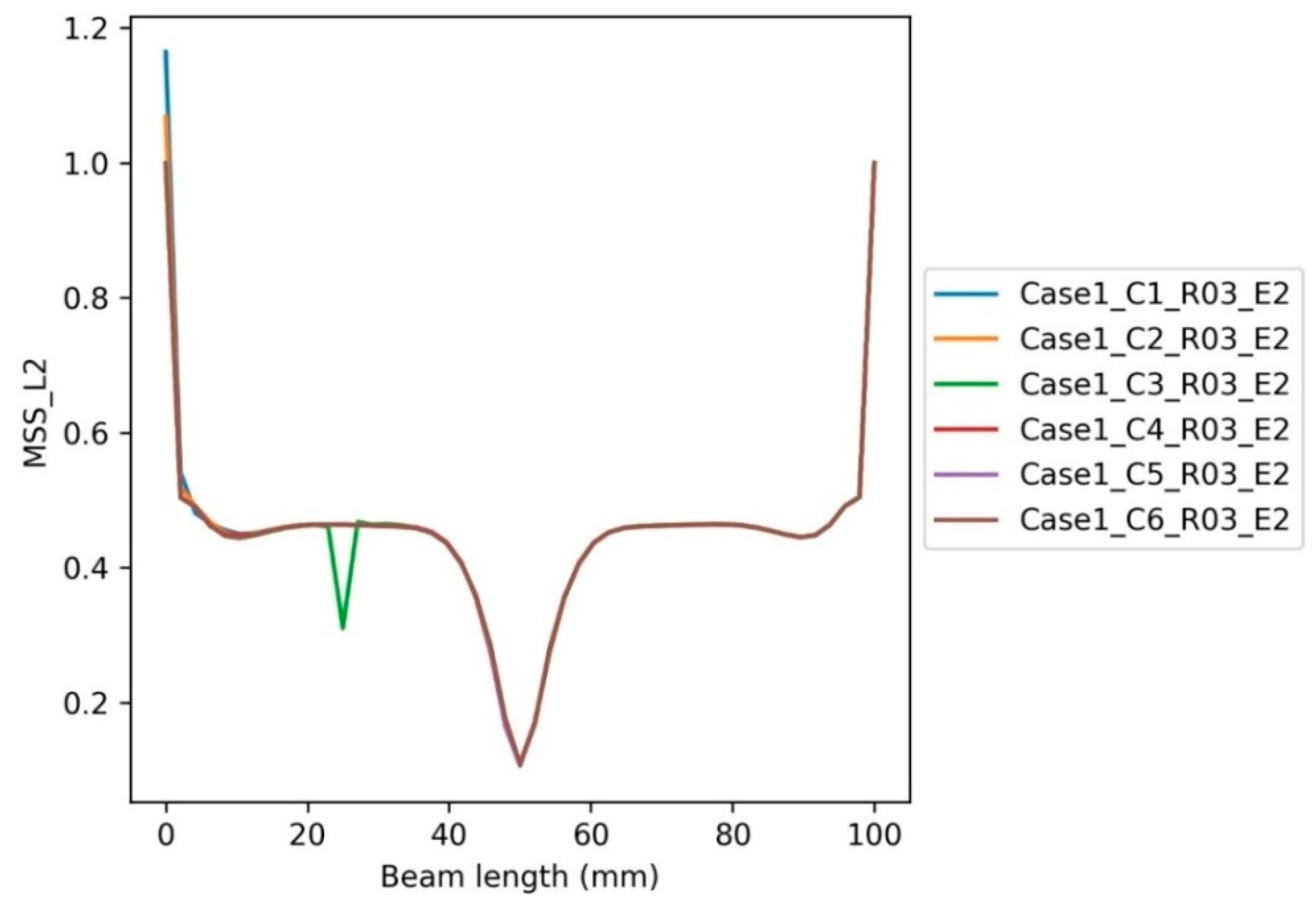
In Group 1-Case 1, the effect of varying inclusion positions on MSS and MAPS along layer 3 (L3) and layer 2 (L2) of the beam is explored. As discussed earlier, in case 1, the inclusions are considered to be present equally in the upper face material and core material along L3 and lower face material and core material along L2. The position of the inclusion is varied along L2 and L3 at a distance of 0 mm, 25 mm, and 50 mm, with respect to the left end of the beam, while the defect geometry radius and Young’s modulus are taken constantly as 0.3 mm (R3) and 26 MPa (E2), respectively. The inclusions at layer 2 are represented as C1, C3, and C5, while those placed along layer 3 are represented as C2, C4, and C6 at a distance of 0 mm, 25 mm, and 50 mm, respectively. Figure 17 depicts the effect of varying inclusion positions, along L3, on the MSS of the beam.
The MSS values of the beam for Case 1_C2_R03_E2 and Case 1_C4_R03_E2 are compared to the corresponding values of MSS at 100 mm and 75 mm on the right side of the beam (i.e., the inclusion-free half of the beam), respectively. The MSS of the beam at inclusion Case 1_C6_R03_E2 (i.e., center of the beam) lies at equidistance from both ends; thus, its value is compared to the average of the nearest MSS values of other inclusions at 50 mm. The value of MSS at a certain point in the inclusion region is taken and tabulated as a percentage of the MSS value at the corresponding symmetric location in the defect-free half of the beam. The same practice is carried out for all the points across L3 (and similarly for L2 in succeeding sections), and the acquired data are plotted along the beam length, as shown in Figure 17. The obtained graph is thereafter explored to study the behavior. It is to be noted that the same pattern of analysis is adopted for all the succeeding readings of MSS and MAPS distribution.
As per the above considerations, the normalized MSS for Case 1_C2_R03_E2 and Case 1_C4_R03_E2 is reduced to 43% and 85% of the corresponding MSS value of the inclusion-free half. Similarly, the MSS value of inclusion Case 1_C6_R03_E2 drops to 94% of the corresponding average MSS value. It depicts that C2, C4, and C6 inclusions exhibit a decrease of 57%, 15%, and 6% in MSS values compared to defect-free values. It can also be observed that as we move away from the center, the normalized MSS decreases and falls exponentially. It might be due to the fact that at the center of the beam, the impact of loadings is severe, and hence, higher MSS is observed compared to that away from the center. Furthermore, the normalized MSS value at Case 1_C1_R03_E2, Case 1_C3_R03_E2, and Case 1_C5_R03_E2 is more compared to the corresponding normalized MSS value at 0 mm, 25 mm, and 50 mm, along L3, respectively, as shown in Figure 17. The increase in MSS for C5 alone is about 67% more compared to the average MSS values of other inclusions at 50 mm. It can be concluded that the presence of inclusions along L3 causes higher decreases in normalized MSS in the compression region than in the tensile region. Thus, under flexural loading and inclusions along L3, the tensile region will be more prone to failure than the compression region [61]. The decrease in MSS along L3 can be attributed to the presence of inclusions in the compression region which opposes the net shearing effect and hence causes a higher decrease in MSS.
Figure 18 depicts the effect t of varying inclusion positions, along L2, on the MSS of the beam. C1, C3, and C5 lie on L2; thus, the normalized MSS values for the said inclusions are observed and analyzed.
As shown in Figure 18, the normalized MSS for Case 1_C1_R03_E2 is increased by 17%, and Case 1_C3_R03_E2 is reduced to 68% of the corresponding MSS value of the inclusion-free half. However, the normalized MSS value at Case 1_C5_R03_E2 remains unchanged. It depicts that the presence of inclusions, as we move away from the center, initially causes a drastic decrease in MSS and later on increases as the end of the beam approaches. The reduction in MSS at C3 can be attributed to the fact that while moving away from the point of impact of flexural loading, the severity of MSS to the presence of inclusions decreases. However, the same normalized MSS value near the regular support of the beam increases in the presence of inclusion and surpasses the MSS value of the corresponding inclusion-free half. This increase might be due to counter shear stress induced in the inclusion due to the reactive force of the beam support, which affects its capability to withstand higher shear stress.
It can further be noted from Figure 18 that the MSS at C1 on L2 is more than the MSS at the corresponding 0 mm position on L3, while the MSS value at C3 on L2 is less than the MSS at the corresponding 25 mm position on L3. This validates that while moving away from the center, inclusion along L2 increases the normalized MSS in the tensile region compared to the compression region. It is worth mentioning that at the center of the beam (i.e., at 50 mm from the reference end), the MSS for C5 along L2 is almost similar to the corresponding MSS along L3. Hence, the presence of inclusion along L2 does not affect the MSS at the center of the beam [62]. The increase in MSS along L2, while moving away from the center, might be due to the tensile nature of the region, which keeps the inclusions under tension at the same time when shearing stress is observed due to the point loading. The simultaneous combination of stresses makes the tensile region more prone to failure under flexural loading.
Figure 19 depicts the effect of varying inclusion positions, along L3, on MAPS of the beam. Inclusions C2, C4, and C6 lie on L3. Thus, the MAPS values for the said inclusions are observed and analyzed. The MAPS for Case 1_C2_R03_E2 and Case 1_C4_R03_E2 is increased by 205% and 1700% compared to the corresponding MAPS values of the inclusion-free half. Similarly, the MAPS value of Case 1_C6_R03_E2 drops to 96% of the corresponding average MAPS value. It depicts that the presence of inclusions along L3 causes an exponential increase in MAPS compared to related MAPSs at the exact location in the defect-free half of the beam. The increase in MAPS while moving away from the center of the beam is more drastic, though it slows down near the end of the beam; however, the net change in MAPS remains higher than the corresponding MAPS at the defect-free half.
It can be concluded that the presence of inclusions in the compressive region causes higher MAPS as compared to the inclusion-free half. It makes the compression region more vulnerable to failure. Furthermore, at the center of the beam, the average MAPS at C6 gets reduced due to direct flexural loading and inclusion. This decrease might be due to the compressive behavior of the region, which opposes the net MAPS due to direct flexural loading at the center. As shown in Figure 19, the normalized MAPS at C2 and C4, along L3, is higher compared to the corresponding normalized MAPS at 0 mm and 25 mm, along L2, respectively. In contrast, the MAPS at C6 on L3 is lower compared to the MAPS at 50 mm on L2. It may be inferred, therefore, that the MAPS in the tensile zone is more significant near the center. The MAPS of the compression zone, as opposed to the tensile region, is increased as one moves out from the center due to the existence of inclusion along L3 [63]. The decrease in MAPS along L3 at the center can be attributed to the compressive nature of the region, which opposes the net MAPS.
Furthermore, the presence of inclusions in the compressive region, at the impact of flexural loading, neutralizes the MAPS more as compared to the tensile area. However, as we move away from the center, the stresses produced due to point load generally increase and reach a maximum value at the end of the beam. In the current cases, the increase in MAPS is more severe in the compressive region as compared to the tensile region. This higher increase might be due to the higher severity associated with localized inclusions in the compressive region as we move away from the center.
Figure 20 depicts the effect of varying inclusion positions, along L2, on the MAPS of the beam. Inclusions C1, C3, and C5 lie on L2. Thus, the MAPS values for the said inclusions are observed. The presence of inclusion at C1, along L2, increases the normalized MAPS from 0 to 0.4, while MAPS at inclusion C3, along L2, is decreased by 17% to the total value of MAPS at the corresponding locations in the defect-free region of the beam. Furthermore, the MAPS at inclusion C5 is increased by 0.17. It can be concluded that the presence of inclusions along L2 initially causes a sharp decrease in MAPS while moving away from the center at 25 mm, but the MAPS increases as it approaches the end of the beam. This increase in MAPS near the beam support might be due to the reaction of the fixed support, which tends to oppose the applied flexural load and hence increases the principal stress capability of the beam. It can be observed from Figure 18 and Figure 19 that the MAPS at C1 and C5, along L2, is more compared to the MAPS at 0 mm and 50 mm, along L3, while at C3, the MAPS is lesser along L2 compared to MAPS at 25 mm along L3. Thus, it can be stated that the presence of inclusions along L2 initially causes a decrease in MAPS capability of the tensile region as compared to the compression region. However, the MAPS for the tensile zone of the beam surpasses the MAPS of the compression region at the end of the beam (i.e., at 0 mm from reference) [64]. The increase in MAPS along L2, as we move away from the center, can be attributed to the tensile nature of the region where the inclusions undergo tensile stress, which ultimately complements the MAPS in the said region.
In Group 2-Case 2, the effect of varying inclusion geometry—radius on MSS and MAPS—is explored such that the inclusions are considered to be placed in upper face material and lower face material along L3 and L2, respectively, at a constant position of 25 mm from the center (i.e., C4), along L3, and C3, along L2, and unchanged Young’s modulus of 26 MPa (E02). The radius of inclusion is varied at: R01 0.1 mm; R03 0.3 mm; and R05 0.5 mm. The effect of varying radii of inclusion C4, along L3 (i.e., in the upper face material), on the MSS of the beam is studied. The MSS for Case 2_C4_R01_E2, Case 2_C4_R03_E2, and Case 2_C4_R05_E2 are evaluated, and the percentage value of the same, compared to the corresponding MSS values at 75 mm, the defect-free half of the beam, is graphically represented along the beam length, as shown in Figure 20. The same analysis pattern is also followed for the rest of the evaluation.
Figure 21 depicts that with the corresponding increase in radius of defect, the MSS for Case 2_C4_R01_E2, Case 2_C4_R03_E2, and Case 2_C4_R05_E2 decreases by 687%, 553%, and 383%, respectively. The increase in defect radius creates a more significant material discontinuity and hence more localized stresses, which ultimately affect the strength of the beam. It is worth mentioning that for the given range of radii, the net MSS remains lower than the corresponding MSS at the symmetric location (i.e., 75 mm in the defect-free region) [65].
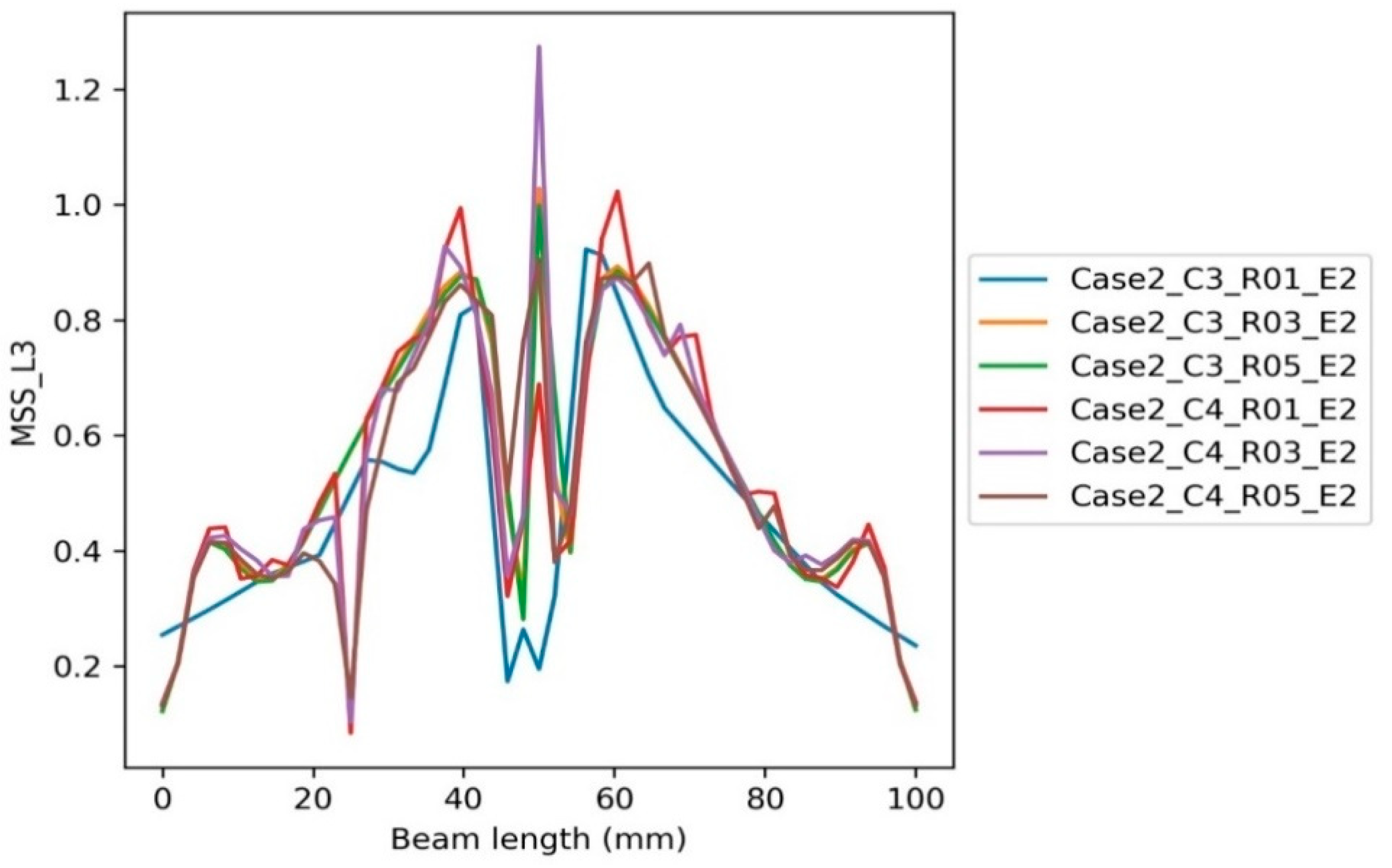
Figure 22 depicts the effect of changing defect radius of inclusion C3 along L2 (i.e., lower face material) on the MSS of the beam. The MSS for Case 2_C3_R01_E2, Case 2_C3_R03_E2, and Case 2_C3_R05_E2 is plotted along the length of the beam. For Case 2_C3_R01_E2 and Case 2_C3_R05_E2, the MSS values increased by 20% and 17%, respectively, as compared to the corresponding defect-free MSS value at 75 mm. However, for Case 2_C3_R03_E2, the MSS dropped by 15%. Thus, it can be concluded that, initially, with an increase in inclusion radius from R01 to R03, the MSS decreases but later increases with a further increase in the radius from R03 to R05.
Comparing Figure 21 and Figure 22, it can further be observed that the MSS for varying radii of inclusion C3 along L2 (i.e., tensile region) is way higher than the corresponding MSS for inclusion C4 along L3 (i.e., compression region). Therefore, increasing defect radius in the tensile region affects the MSS, and so does strength, more severely as compared to the compression region (compare the MSS values for Case 2_C3_R05_E2 and Case 2_C4_R05_E2) [66]. The increase in radius of the inclusion along L3 helps neutralize the shearing effect due to the compressive nature of the region. That is why the severity of MSS for varying radii of inclusion along L2 is more in tensile region where the increase in radius gives rise to more localized stresses.
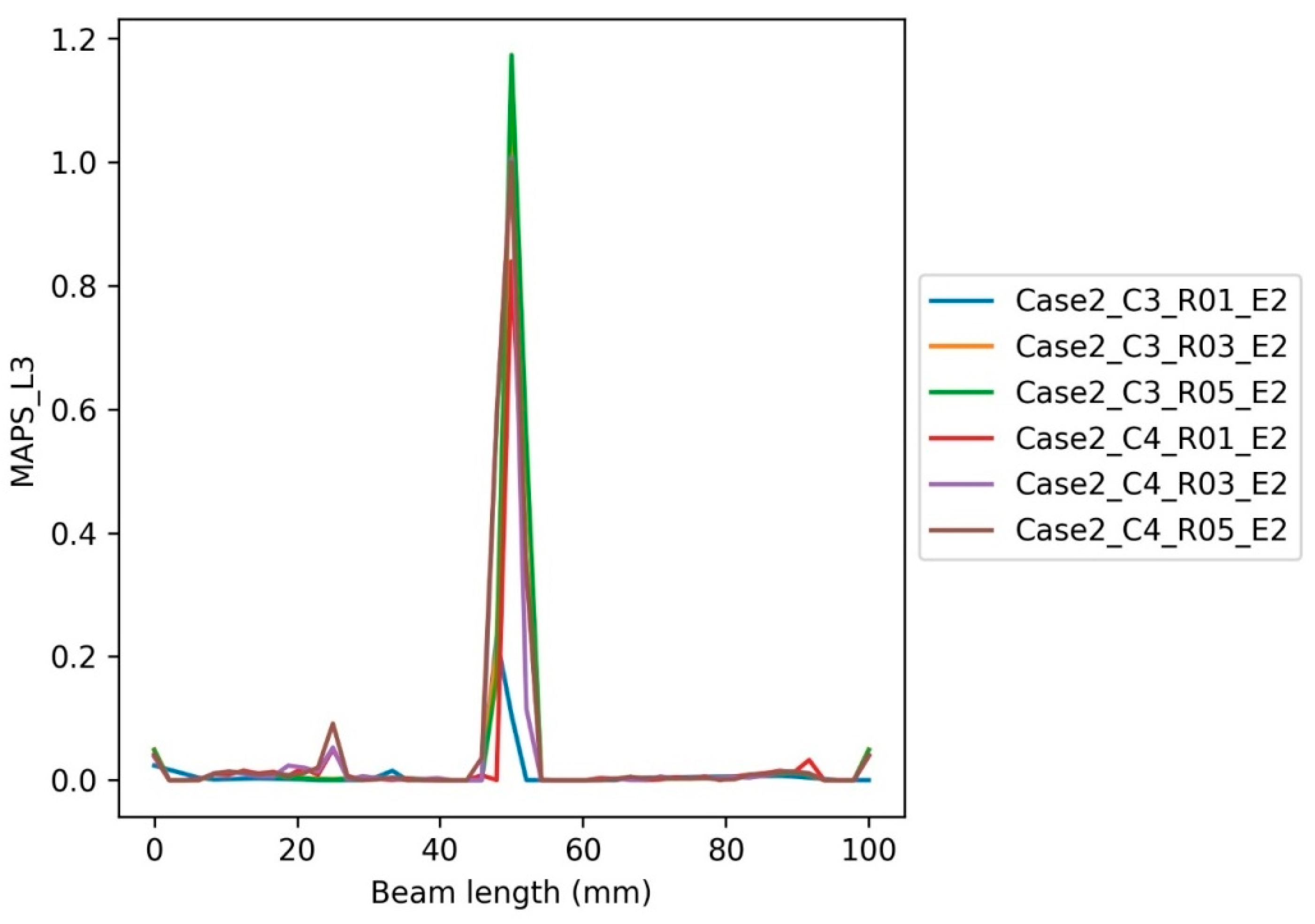
In Figure 23, the effect of varying radii of inclusion C4 along L3 (i.e., in upper face material) on the MAPS of the beam is explored. The MAPS for Case 2_C4_R01_E2, Case 2_C4_R03_E2, and Case 2_C4_R05_E2 are evaluated. It can be observed that the MAPS for Case 2_C4_R01_E2, Case 2_C4_R03_E2 and Case 2_C4_R05_E2 increase by 20, 17.33, and 36 times as compared to the MAPS of a corresponding defect-free location (i.e., 75 mm along L3). The increase in the MAPS with increasing defect radius can be due to the fact that the localized stresses that arise due to inclusion may add up to the beam stresses such that the net principal stress of the beam increases [67].
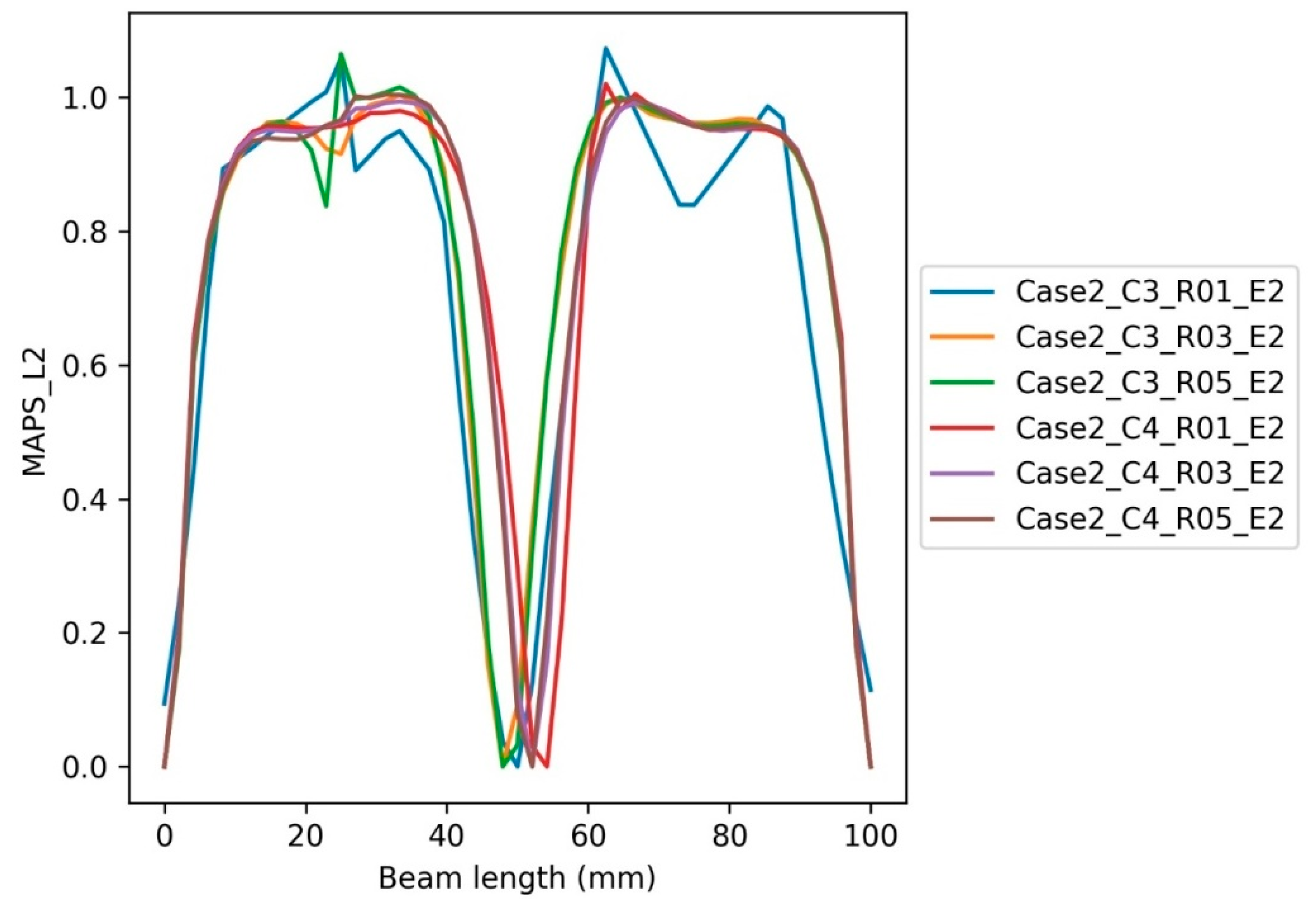
Figure 24 depicts the effect of changing the defect radius of inclusion C3, along L2 (i.e., lower face material) on the MAPS of the beam. The MSS for Case 2_C3_R01_E2, Case 2_C3_R03_E2, and Case 2_C3_R05_E2 are plotted along the length of the beam. It can be observed that for Case 2_C3_R01_E2 and Case 2_C3_R05_E2, the MAPS value increased by 25% and 5%, respectively, as compared to the corresponding defect-free MAPS values at 75 mm. However, for Case 2_C3_R03_E2, the MSS decreased by 15% as compared to the corresponding defect-free MAPS value at 75 mm. Thus, it can be concluded that, initially, with an increase in inclusion radius from R01 to R03, the MAPS decreases but increases with a further increase in radius from R03 to R05.
Comparing Figure 23 and Figure 24, it can further be observed that the MAPS for an increasing radius of inclusion C3 along L2 (i.e., the tensile region) is much higher than the corresponding MAPS for inclusion C4 along L3 (i.e., compression region). Consequently, increasing defect radius in the tensile region affects the MAPS more severely than the compression region (compare MAPS values for Case 2_C3_R05_E2 and Case 2_C4_R05_E2). As a result, for any increase in inclusion radius, the tensile region will be more prone to failure than the compression region [68]. The decrease in MAPS, for varying radii of inclusions, in the compression region might be due to the fact that the inclusions in the compression region oppose the net MAPS, hence resulting in minimal MAPS.
In Group 3-Case 3, the effect of varying inclusion of Young’s modulus (E) on MSS and MAPS is explored. The inclusions are considered to be placed in core material along L3 and L2, at a constant position of 25 mm from the center (i.e., C4), along L3, and C3, along L2. The Young’s modulus of inclusion is varied at E1 0.26 MPa, E2 26 MPa, and E3 1051 MPa. The geometry—radius—of inclusion is also kept constant at R03.
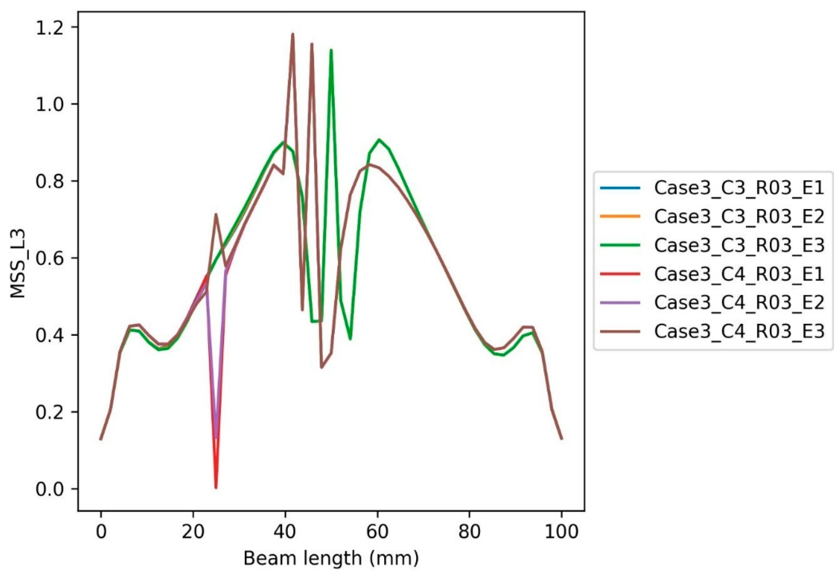
In Figure 25, the effect of varying moduli of elasticity (E) of inclusion C4, along L3, on MSS is studied. The MSS for Case 3_C4_R03_E1, Case 3_C4_R03_E2, and Case 3_C4_R03_E3 is evaluated and the percentage value of the same, compared to the corresponding MSS values at 75 mm, the defect-free half of the beam, is graphically represented along the beam length, as shown in Figure 21. The same analysis pattern is also followed for the rest of the evaluation. Figure 25 depicts that with the corresponding increase in Young’s modulus of defect, the MSS for Case 3_C4_R03_E1 and Case 3_C4_R03_E2 decreased by 100% and 79%, respectively, and increased for Case 3_C4_R03_E3 by 26% for a corresponding increase in the value of E. Due to the presence of relatively low-strength inclusions, the rise in defect elasticity up to E2 reduces the MSS of the beam as compared to the related MSS at 75 mm. However, upon reaching E3, the defect elasticity was considerably higher compared to the core material E, thus inducing higher MSS [69].
Figure 26 describes the effect of changing the elastic modulus of inclusion C3, along L2, on the MSS of the beam. The MSS for Case 3_C3_R03_E1, Case 3_C3_R03_E2, and Case 3_C3_R03_E3 is plotted along the length of the beam. Figure 26 reveals that for Case 3_C3_R03_E1, the MSS value is reduced by 99%. The MSS for Case 3_C3_R03_E2 remains almost unchanged as the modulus of elasticity of inclusion equals that of the core material. The MSS value for Case 3_C3_R03_E3 is increased by nearly five times (500%) as compared to the corresponding MSS value at 75 mm (i.e., defect-free half). It can be summed up that the elastic modulus of inclusion negatively affects the MSS at lower value E1, and change in MSS is negligible for E2 as both E2 and core material Young’s modulus are equal (i.e., 26 MPa). However, at higher E (i.e., E3 at 1051 MPa), the MSS is enhanced exponentially. The increase in MSS for higher E can be attributed to higher elasticity inclusions in the core material, which has a relatively lower E. These higher-elasticity inclusions contribute to inducing a higher MSS.
Comparing Figure 26 and Figure 25, it can further be noted that the MSS for varying Young’s moduli of inclusion C3 along L2 (i.e., tensile region) is way higher than the corresponding MSS for inclusion C4 along L3 (i.e., compression region). Thus, the severity of MSS and chances of failure with an increase in E are higher in the tensile region as compared to the compression region (compare MSS for Case 3_C3_R03_E3 and Case 3_C4_R03_E3) [70]. The severity of MSS for changing the Young’s modulus of inclusions along L2 can be attributed to the tensile nature of the region. Unlike the tensile region where the inclusions cause localized stresses, the presence of high-strength inclusions in the compression region neutralizes the net shearing effect due to the compressive nature of the region, hence minimizing the MSS.
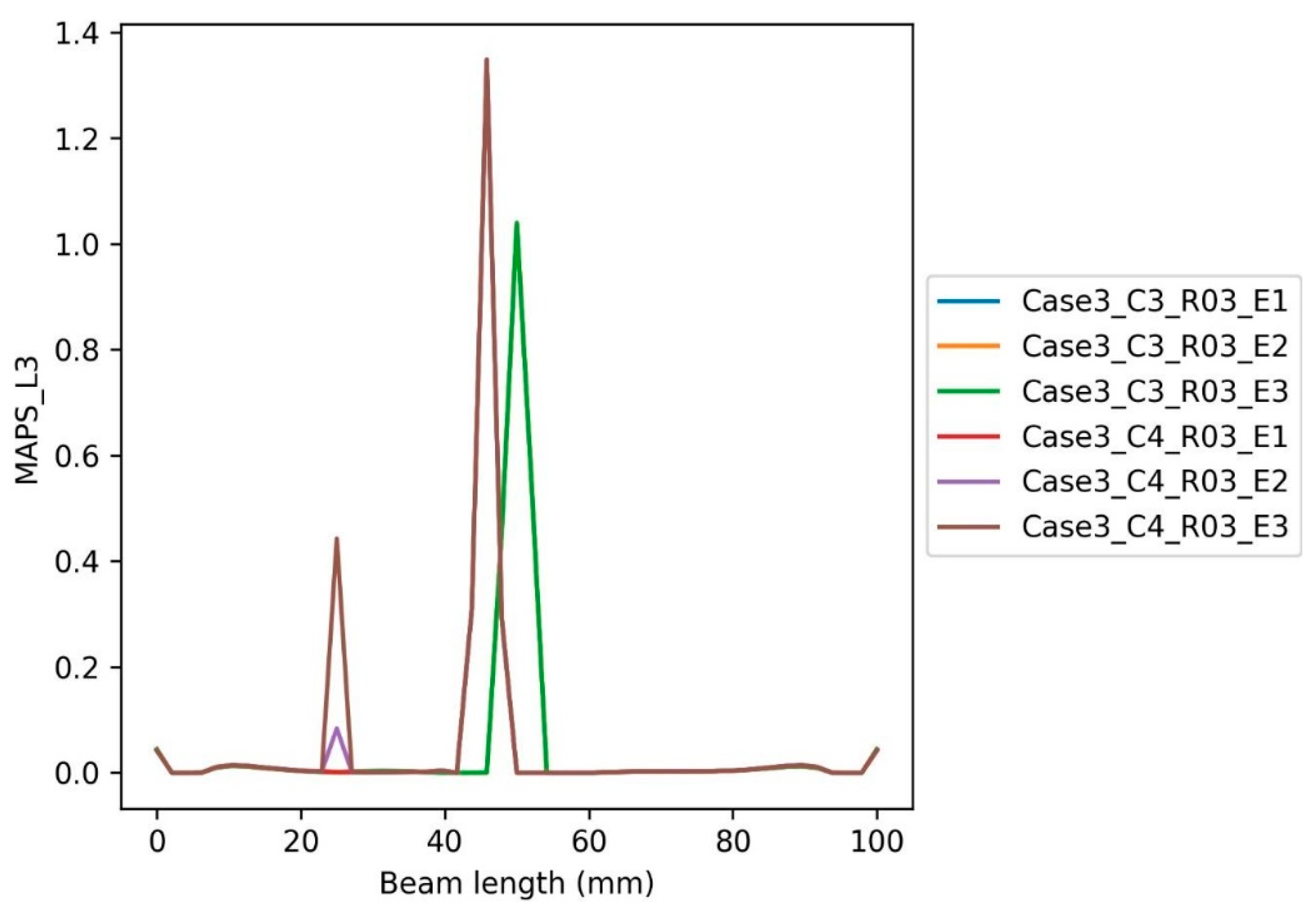
Figure 27 explores the effect of varying Young’s moduli (E) of inclusion C4, along L3, on MAPS. The MAPS for Case 3_C4_R03_E1, Case 3_C4_R03_E2, and Case 3_C4_R03_E3 are depicted in Figure 27. Figure 27 reveals that with the corresponding increase in Young’s modulus of defect, the MAPS for Case 3_C4_R03_E1 is decreased by 52%, while for Case 3_C4_R03_E2 and Case 3_C4_R03_E3, the MAPS is increased by 35 times and 191 times, respectively. At comparatively lower values of Young’s moduli (E1 of inclusion), the MAPS is reduced due to the presence of inclusion with lower elastic moduli, which induces lower stresses. However, as the modulus of elasticity increases (i.e., at E2 and E3), the MAPS severity increases exponentially. This increase in the MAPS might be due to the presence of higher elasticity inclusions in comparatively lower elastic core material, which contribute to inducing higher localized MAPS [71].
In Figure 28, the effect of varying Young’s moduli (E) of inclusion C3, along L2, on MAPS is explored. The MAPS for Case 3_C3_R03_E1, Case 3_C3_R03_E2, and Case 3_C3_R03_E3 are shown in Figure 28. Figure 28 depicts that with the corresponding increase in Young’s modulus of inclusion, the MAPS for Case 3_C4_R03_E1 is decreased by 70%, while for Case 3_C4_R03_E2 it remains unchanged, and for Case 3_C4_R03_E3, the MAPS is increased by five times (i.e., 500%). At comparatively lower values of Young’s moduli (E1 of inclusion), the MAPS is reduced due to the presence of inclusion with lower elastic moduli, which does not contribute to inducing MAPS at higher flexural loadings. The change in MAPS is negligible for E2 as both E2 and core material Young’s modulus are equal (i.e., 26 MPa). However, as the Young’s modulus is increased to E3, the MAPS is increased exponentially. This increase in MAPS might be due to the presence of higher elasticity inclusions in the comparatively lower elastic core material, which can induce higher MAPS in the localized vicinity.
Comparing Figure 27 and Figure 28, it can further be noted that the MAPS for varying Young’s moduli of inclusion C3 along L2 (i.e., tensile region) is way higher than the corresponding MAPS for inclusion C4 along L3 (i.e., compression region). Thus, the severity of MAPS with an increase in modulus of elasticity is higher in the tensile region than in the compression region (compare MAPS for Case 3_C3_R03_E3 and Case 3_C4_R03_E3) [72]. The decrease in MAPS, for varying Young’s moduli of inclusions, in the compression region might be due to the fact that the high modulus inclusions in the compression region oppose the net MAPS, hence resulting in minimal MAPS.

7. Concluding Remarks

Using additive manufacturing technology to produce sandwich sections components with multi-layer materials faces industrial challenges as well as safety concerns that are related to inclusions that could exist during the printing process, and this could be very serious and a real problem, especially with recycled material that comes from different resources [73,74,75], whether from 3D Printing waste or customized filaments that is reinforced with particles or fibers [76,77,78]. In this study, a fine-element model was used to investigate the impact of inclusions on the mechanical characteristics of 3D-printed composite sandwich beams that could initiate when printing the layers. The effects of defects related to maximum shear stress and maximum principal stress using the Ansys simulation tool were investigated. The results revealed that the midpoint of the composite is highly stressed, and the concentration of stress decreases outward as we move toward the edges of the composite. This is because the load acts at the midpoint of the beam, and there are no support reactions at the center point unless at both ends.
For the intact case, the deformation was maximum at the center of the composite and minimum at both ends. The maximum shear stress was highest at the center and decreased gradually as we approached the ends on both sides, making the shear stress distribution symmetrical. The MAPS is constant throughout the beam apart from the lower face of the beam and is maximum at the face material. The high maximum shear stress at the center of the beam is due to the high concentration of the load. The upper part of the beam experienced tension which is dangerous if uncontrolled since it may lead to the failure of the beam. The MSS, on the other hand, is high at the endpoints where we have the support reactions, which may weaken the entire material’s mechanical properties.
For Case 1 along L3, it was observed that the MSS values decrease as we move away from the center, which may cause failure at the ends compared to the beam center. This weakens the material bonding at about 70 mm from the 0 mm point and thus may result in the collapse of the beam. The normalized MSS in the compression region will be lower than the corresponding MSS in the tensile region. For Case 1 along L2, the normalized MSS value near the supports increases, possibly due to the reaction supports at the ends. It was also observed that the presence of inclusion along L2 does not affect the MSS at the center of the beam. In summary, the presence of inclusions along L2 initially causes a sharp decrease in MAPS while moving away from the center at 25 mm, but the MAPS increases as it approaches the end of the beam. This increase in the MAPS near the beam support might be due to the reaction of the fixed support, which tends to oppose the applied flexural load and hence increases the principal stress capability of the beam. It is further noted that the presence of inclusions along L2 initially causes a decrease in the MAPS capability of the tensile region as compared to the compression region. However, the MAPS for the tensile region of the beam surpasses the MAPS of the compression region at the end of the beam.
For Case 2, the effect of inclusion due to radius changes for E3 as the radius increases and the material dissimilarity increases, thus leading to more localized stresses, which affected MSS negatively. Additionally, the MAPS effect increased as the effect of inclusion went up due to an increase in radius. However, the MAPS decreased from R01 to R03 and then decreased for R03 to R05. For E3, it was observed that initially, with an increase in inclusion radius, from R01 to R03, the MSS decreases but then increases with a further increase in radius from R03 to R05. Therefore, increasing defect radius in the compression region affects the MSS more severely as compared to the tensile region; compare MSS for Case 2_C3_R05_E2 and Case 2_C4_R05_E2. Additionally, for E2 at R05, the MSS is highest at the ends of the beam where there are support reactions. Increasing defect radius in the compression region affects the MAPS more severely as compared to the tensile region.
For Case 3, the effect of the defect on the Young’s modulus E2 lowers the MSS capability, but, at E3, the effect is higher as compared to that of the core material, thus making the materials of MSS higher and more sustainable. Therefore, higher elasticity inclusions make the MSS values stronger and more bearable. High values of MAPS with a high modulus of elasticity are higher in the tension region as compared to the compression region.

Author Contributions

Conceptualization, E.Z.; Funding acquisition, W.A.; Investigation, W.A.; Methodology, A.E.H. and W.A.; Project administration, W.A.; Software, A.E.H.; Validation, E.Z.; Writing–original draft, A.E.H.; Writing–review & editing, E.Z. All authors have read and agreed to the published version of the manuscript.

Funding

This research was funded by UAE University, grant number G00003693.

Data Availability Statement

Not Applicable.

Conflicts of Interest

The authors declare no conflict of interest.

References

  1. Calignano, F.; Manfredi, D.; Ambrosio, E.P.; Biamino, S.; Lombardi, M.; Atzeni, E.; Salmi, A.; Minetola, P.; Iuliano, L.; Fino, P. Overview on additive manufacturing technologies. Proc. IEEE 2017, 105, 593–612. [Google Scholar] [CrossRef]
  2. Ngo, T.D.; Kashani, A.; Imbalzano, G.; Nguyen, K.T.; Hui, D. Additive manufacturing (3D printing): A review of materials, methods, applications and challenges. Compos. Part B Eng. 2018, 143, 172–196. [Google Scholar]
  3. Singh, S.; Ramakrishna, S.; Singh, R. Material issues in additive manufacturing: A review. J. Manuf. Process. 2017, 25, 185–200. [Google Scholar] [CrossRef]
  4. Stansbury, J.W.; Idacavage, M.J. 3D printing with polymers: Challenges among expanding options and opportunities. Dent. Mater. 2016, 32, 54–64. [Google Scholar] [CrossRef]
  5. Tofail, S.A.; Koumoulos, E.P.; Bandyopadhyay, A.; Bose, S.; O’Donoghue, L.; Charitidis, C. Additive manufacturing: Scientific and technological challenges, market uptake and opportunities. Mater. Today 2018, 21, 22–37. [Google Scholar] [CrossRef]
  6. Fateri, M.; Kaouk, A.; Cowley, A.; Siarov, S.; Palou, M.V.; González, F.G.; Marchant, R.; Cristoforetti, S.; Sperl, M. Feasibility study on additive manufacturing of recyclable objects for space applications. Addit. Manuf. 2018, 24, 400–404. [Google Scholar] [CrossRef]
  7. Gill, S.S.; Arora, H.; Sheth, V. On the development of Antenna feed array for space applications by additive manufacturing technique. Addit. Manuf. 2017, 17, 39–46. [Google Scholar] [CrossRef]
  8. Saltzman, D.; Bichnevicius, M.; Lynch, S.; Simpson, T.W.; Reutzel, E.W.; Dickman, C.; Martukanitz, R. Design and evaluation of an additively manufactured aircraft heat exchanger. Appl. Therm. Eng. 2018, 138, 254–263. [Google Scholar] [CrossRef]
  9. Huang, R.; Riddle, M.; Graziano, D.; Warren, J.; Das, S.; Nimbalkar, S.; Cresko, J.; Masanet, E. Energy and emissions saving potential of additive manufacturing: The case of lightweight aircraft components. J. Clean. Prod. 2016, 135, 1559–1570. [Google Scholar] [CrossRef]
  10. Zeltmann, S.E.; Gupta, N.; Tsoutsos, N.G.; Maniatakos, M.; Rajendran, J.; Karri, R. Manufacturing and security challenges in 3D printing. JOM 2016, 68, 1872–1881. [Google Scholar] [CrossRef]
  11. Schwarzer, E.; Holtzhausen, S.; Scheithauer, U.; Ortmann, C.; Oberbach, T.; Moritz, T.; Michaelis, A. Process development for additive manufacturing of functionally graded alumina toughened zirconia components intended for medical implant application. J. Eur. Ceram. Soc. 2019, 39, 522–530. [Google Scholar] [CrossRef]
  12. Javaid, M.; Haleem, A. Additive manufacturing applications in medical cases: A literature based review. Alex. J. Med. 2018, 54, 411–422. [Google Scholar] [CrossRef]
  13. Rinaldi, M.; Ghidini, T.; Cecchini, F.; Brandao, A.; Nanni, F. Additive layer manufacturing of poly (ether ether ketone) via FDM. Compos. Part B Eng. 2018, 145, 162–172. [Google Scholar] [CrossRef]
  14. Turhan, D.; Celep, Z.; Zain-Edden, I.K. Transient wave propagation in layered media conducting heat. J. Sound Vib. 1991, 144, 247–261. [Google Scholar] [CrossRef]
  15. Ahmed, W.K.; Al-Rifaie, W.N. The impact of cracked microparticles on the mechanical and the fracture behavior of particulate composite. J. Nano- Electron. Phys. 2015, 7, 3008–3011. [Google Scholar]
  16. Sugiyama, K.; Matsuzaki, R.; Ueda, M.; Todoroki, A.; Hirano, Y. 3D printing of composite sandwich structures using continuous carbon fiber and fiber tension. Compos. Part A Appl. Sci. Manuf. 2018, 113, 114–121. [Google Scholar] [CrossRef]
  17. Carlsson, L.A.; Kardomateas, G.A. Structural and Failure Mechanics of Sandwich Composites; Springer Science & Business Media: Berlin, Germany, 2011; Volume 121. [Google Scholar]
  18. Emami, S. Development of Probabilistic Models for Long Term Reliability of Sandwich Composites in Saline Freeze/Thaw Environment for Civil Engineering Applications. Doctoral Dissertation, University of Dayton, Dayton, OH, USA, 2017. [Google Scholar]
  19. Ning, H.; Janowski, G.M.; Vaidya, U.K.; Husman, G. Thermoplastic sandwich structure design and manufacturing for the body panel of mass transit vehicle. Compos. Struct. 2007, 80, 82–91. [Google Scholar] [CrossRef]
  20. Karlsson, K.F.; TomasÅström, B. Manufacturing and applications of structural sandwich components. Compos. Part A Appl. Sci. Manuf. 1997, 28, 97–111. [Google Scholar] [CrossRef]
  21. Jakobsen, J.; Bozhevolnaya, E.; Thomsen, O.T. New peel stopper concept for sandwich structures. Compos. Sci. Technol. 2007, 67, 3378–3385. [Google Scholar] [CrossRef]
  22. Sypeck, D.J.; Wadley, H.N. Cellular metal truss core sandwich structures. Adv. Eng. Mater. 2002, 4, 759–764. [Google Scholar] [CrossRef]
  23. Dudek, P.F.D.M. FDM 3D printing technology in manufacturing composite elements. Arch. Metall. Mater. 2013, 58, 1415–1418. [Google Scholar] [CrossRef]
  24. Bates, S.R.; Farrow, I.R.; Trask, R.S. 3D printed polyurethane honeycombs for repeated tailored energy absorption. Mater. Des. 2016, 112, 172–183. [Google Scholar] [CrossRef] [Green Version]
  25. Yap, Y.L.; Yeong, W.Y. Shape recovery effect of 3D printed polymeric honeycomb: This paper studies the elastic behaviour of different honeycomb structures produced by PolyJet technology. Virtual Phys. Prototyp. 2015, 10, 91–99. [Google Scholar] [CrossRef]
  26. Chen, Y.; Li, T.; Jia, Z.; Scarpa, F.; Yao, C.W.; Wang, L. 3D printed hierarchical honeycombs with shape integrity under large compressive deformations. Mater. Des. 2018, 137, 226–234. [Google Scholar] [CrossRef]
  27. Sarvestani, H.Y.; Akbarzadeh, A.H.; Niknam, H.; Hermenean, K. 3D printed architected polymeric sandwich panels: Energy absorption and structural performance. Compos. Struct. 2018, 200, 886–909. [Google Scholar] [CrossRef]
  28. Sarvestani, H.Y.; Akbarzadeh, A.H.; Mirbolghasemi, A.; Hermenean, K. 3D printed meta-sandwich structures: Failure mechanism, energy absorption and multi-hit capability. Mater. Des. 2018, 160, 179–193. [Google Scholar] [CrossRef]
  29. Ang, K.C.; Leong, K.F.; Chua, C.K.; Chandrasekaran, M. Investigation of the mechanical properties and porosity relationships in fused deposition modelling-fabricated porous structures. Rapid Prototyp. J. 2006, 12, 100–105. [Google Scholar]
  30. Gebisa, A.W.; Lemu, H.G. Investigating effects of fused-deposition modeling (FDM) processing parameters on flexural properties of ULTEM 9085 using designed experiment. Materials 2018, 11, 500. [Google Scholar] [CrossRef]
  31. Calignano, F.; Lorusso, M.; Roppolo, I.; Minetola, P. Investigation of the mechanical properties of a carbon fibre-reinforced nylon filament for 3D printing. Machines 2020, 8, 52. [Google Scholar] [CrossRef]
  32. Hsueh, M.H.; Lai, C.J.; Liu, K.Y.; Chung, C.F.; Wang, S.H.; Pan, C.Y.; Huang, W.C.; Hsieh, C.H.; Zeng, Y.S. Effects of Printing Temperature and Filling Percentage on the Mechanical Behavior of Fused Deposition Molding Technology Components for 3D Printing. Polymers 2021, 13, 2910. [Google Scholar] [CrossRef]
  33. Heslehurst, R.B. Defects and Damage in Composite Materials and Structures; CRC Press: Boca Raton, FL, USA, 2014; Volume 19. [Google Scholar]
  34. Ahmed, W.; Alnajjar, F.; Zaneldin, E.; Al-Marzouqi, A.H.; Gochoo, M.; Khalid, S. Implementing FDM 3D Printing Strategies Using Natural Fibers to Produce Biomass Composite. Materials 2020, 13, 4065. [Google Scholar] [CrossRef] [PubMed]
  35. Yeon, Y.M.; Lee, W.; Hong, K.N. Finite Element Analysis of Reinforced Concrete Beams Prestressed by Fe-Based Shape Memory Alloy Bars. Appl. Sci. 2002, 12, 3255. [Google Scholar] [CrossRef]
  36. Ahmad, H.; Elnemr, A.; Ali, N.; Hussain, Q.; Chaiyasarn, K.; Joyklad, P. Finite element analysis of glass fiber-reinforced polymer-(Gfrp) reinforced continuous concrete beams. Polymers 2021, 13, 4468. [Google Scholar] [CrossRef] [PubMed]
  37. Pishro, A.A.; Zhang, Z.; Pishro, M.A.; Liu, W.; Zhang, L. Structural Performance of EB-FRP-Strengthened RC T-Beams Subjected to Combined Torsion and Shear Using ANN. Materials 2022, 15, 4852. [Google Scholar] [CrossRef] [PubMed]
  38. Ultimaker. Ultimaker TPU 95A Technical Datasheet. Available online: https://support.ultimaker.com/hc/en-us/articles/360012664440-Ultimaker-TPU-95A-TDS (accessed on 22 August 2022).
  39. FiberForce Italy. Nylforce Glass Fiber Data Sheet. Retrieved from 2019. Available online: http://www.fiberforce.it/wp-content/uploads/2019/07/TDS_NY-GLASS_REV-2.0.pdf (accessed on 22 August 2022).
  40. Stratford, T.; Cadei, J. Elastic analysis of adhesion stresses for the design of a strengthening plate bonded to a beam. Constr. Build. Mater. 2006, 20, 34–45. [Google Scholar] [CrossRef]
  41. Szeptyński, P. Comparison and experimental verification of simplified one-dimensional linear elastic models of multilayer sandwich beams. Compos. Struct. 2019, 241, 112088. [Google Scholar] [CrossRef]
  42. Stitic, A.; Nguyen, A.C.; Rezaei Rad, A.; Weinand, Y. Numerical Simulation of the Semi-Rigid Behaviour of Integrally Attached Timber Folded Surface Structures. Buildings 2019, 9, 55. [Google Scholar] [CrossRef]
  43. High Flexible Sandwich Panel Made of Glass Fibre Reinforced Nylon with Super Elastic Rubber Core Using Fused Filament Fabrication (FFF). Application Granted 2022-02-01; U.S. Patent US11235514B1. Available online: https://patents.google.com/patent/US11235514B1/en (accessed on 20 July 2022).
  44. Mostafaei, A.; Elliott, A.M.; Barnes, J.E.; Li, F.; Tan, W.; Cramer, C.L.; Nandwana, P.; Chmielus, M. Binder Jet 3D Printing–Process Parameters, Materials, Properties, and Challenges. Prog. Mater. Sci. 2020, 119, 100707. [Google Scholar] [CrossRef]
  45. Ahmed, W.; Alabdouli, H.; Alqaydi, H.; Mansour, A.; Al, K.H.; Al, J.H. Open Source 3D Printer: A Case Study. In Proceedings of the International Conference on Industrial Engineering and Operations Management, Dubai, United Arab Emirates, 10–12 March 2020; pp. 2995–3004. [Google Scholar]
  46. Mansour, A.; Alabdouli, H.; Alqaydi, H.; Al, K.H.; Ahmed, W.; Al, J.H. Evaluating the 3D Printing Capabilities. In Proceedings of the International Conference on Industrial Engineering and Operations Management, Dubai, United Arab Emirates, 10–12 March 2020; pp. 2618–2629. [Google Scholar]
  47. Ahmed, W.; Ahmed, S.; Alnajjar, F.; Zaneldin, E. Mechanical performance of three-dimensional printed sandwich composite with a high-flexible core. Proc. Inst. Mech. Eng. Part L J. Mater. Des. Appl. 2021, 235, 1382–1400. [Google Scholar] [CrossRef]
  48. Ahmed, W.; Zanledin, E.; Kabbani, S. Fracture Mechanics Performance of Through-Thickness Crack of Polymeric 3D Printed Components. Lect. Notes Mech. Eng. 2020, 12, 302. [Google Scholar]
  49. Waleed, A. Product and Method to Manufacture Multi-Layered, Multi-Material Composite Sandwich with Hyper Elasticity Rubber Like Core Made by Fusion Deposition Modelling. US10974444B1 United States Application granted 2021-04-13. Available online: https://patents.google.com/patent/US10974444B1/en (accessed on 20 July 2022).
  50. Gebrehiwot, S.Z.; Espinosa-Leal, L.; Eickhof, J.N.; Rechenberg, L. Correction to: The Influence of Stiffener Geometry on Flexural Properties of 3D-Printed Polylactic Acid (PLA) Beams. Prog. Addit. Manuf. 2020, 5, 421. [Google Scholar] [CrossRef]
  51. Gere, J.M.; Goodno, B.J. Mechanics of Materials; SI ed.; Cengage Learning: Boston, MA, USA, 2008. [Google Scholar]
  52. Barber, J.R. Introduction. In Elasticity; Barber, J.R., Ed.; Springer: Dordrecht, The Netherlands, 2010; pp. 3–24. [Google Scholar]
  53. Practical Guide to Finite Elements—A Solid Mechanics Approach: By Steven M. Lepi–ScienceDirect. Available online: https://www-sciencedirect-com.uaeu.idm.oclc.org/science/article/pii/S0997753898905083?via%3Dihub (accessed on 25 November 2020).
  54. Barber, J.R. Calculation of Displacements. In Elasticity; Barber, J.R., Ed.; Springer: Dordrecht, The Netherlands, 2010; pp. 123–134. [Google Scholar]
  55. ISO 178:2019-Plastics-Determination of Flexural Properties. Available online: https://standards.iteh.ai/catalog/standards/iso/6d9ee8ed-eaf6-49f6-b83b-bd615d3367df/iso-178-2019 (accessed on 25 November 2020).
  56. Barber, J.R. Application to Elasticity Problems. In Elasticity; Barber, J.R., Ed.; Springer: Dordrecht, The Netherlands, 2010; pp. 293–317. [Google Scholar]
  57. Barber, J.R. Thermoelastic Displacement Potentials. In Elasticity; Barber, J.R., Ed.; Springer: Dordrecht, The Netherlands, 2010; pp. 347–361. [Google Scholar]
  58. Bitzer, T.N. Honeycomb Technology: Materials, Design, Manufacturing, Applications and Testing; Springer: Dordrecht, The Netherlands, 1997. [Google Scholar]
  59. Richard, H.; Sander, M.; Fulland, M.; Kullmer, G. Development of fatigue crack growth in real structures. Eng. Fract. Mech. 2008, 75, 331–340. [Google Scholar] [CrossRef]
  60. Fang, Q.; Chen, J.; Liu, Y.; Wen, P. Critical shear stress produced by interaction of edge dislocation with nanoscale inhomogeneity. Bull. Mater. Sci. 2010, 33, 123–127. [Google Scholar] [CrossRef]
  61. Xu, J.; Dong, C. Surface and interface stress effects on the interaction of nano-inclusions and nano-cracks in an infinite domain under anti-plane shear. Int. J. Mech. Sci. 2016, 111–112, 12–23. [Google Scholar] [CrossRef]
  62. Lin, P.; Lin, S.; Pan, J. Modeling of failure near spot welds in lap-shear specimens based on a plane stress rigid inclusion analysis. Eng. Fract. Mech. 2006, 73, 2229–2249. [Google Scholar] [CrossRef]
  63. Yan, A.; Nguyen-Dang, H. Multiple-cracked fatigue crack growth by BEM. Comput. Mech. 1995, 16, 273–280. [Google Scholar] [CrossRef]
  64. Thibodeau, W.E.; Wood, L.A. Photoelastic determination of stresses around a circular inclusion in rubber. J. Frankl. Inst. 1938, 225, 475–476. [Google Scholar] [CrossRef]
  65. Qi, D.; Hu, W.; Xin, K.; Zeng, Q.; Xi, L.; Tao, R.; Liao, H.; Deng, Y.; Liao, B.; Wu, W.; et al. In-situ synchrotron X-ray tomography investigation of micro lattice manufactured with the projection micro-stereolithography (PμSL) 3D printing technique: Defects characterization and in-situ shear test. Compos. Struct. 2020, 252, 112710. [Google Scholar] [CrossRef]
  66. Ma, C.; Zhang, G.; Wang, Y.; Zhang, Z.; Ren, Z. Effect of Non-metallic Inclusions on Subsurface Stress and Fatigue Life of High-speed Railway Bearings. IOP Conf. Ser. Earth Environ. Sci. 2021, 632, 052001. [Google Scholar] [CrossRef]
  67. Tam, K.; Mueller, C. Additive Manufacturing Along Principal Stress Lines. 3D Print. Addit. Manuf. 2017, 4, 63–81. [Google Scholar] [CrossRef]
  68. Wang, J.; Ren, L.; Xie, L.; Xie, H.; Ai, T. Maximum mean principal stress criterion for three-dimensional brittle fracture. Int. J. Solids Struct. 2016, 102–103, 142–154. [Google Scholar] [CrossRef]
  69. Blenkinsop, T. Relationships between faults, extension fractures and veins, and stress. J. Struct. Geol. 2008, 30, 622–632. [Google Scholar] [CrossRef]
  70. Fang, Q.; Liu, Y.; Huang, B.; Liu, Y.; Wen, P. Contribution to critical shear stress of nanocomposites produced by interaction of screw dislocation with nanoscale inclusion. Mater. Lett. 2008, 62, 3521–3523. [Google Scholar] [CrossRef]
  71. Lang, P.; Paluszny, A.; Nejati, M.; Zimmerman, R. Relationship Between the Orientation of Maximum Permeability and Intermediate Principal Stress in Fractured Rocks. Water Resour. Res. 2018, 54, 8734–8755. [Google Scholar] [CrossRef] [Green Version]
  72. Mori, T.; Hirayama, S. Fatigue Crack Propagation and Strength of Web-Gusset Welded Joints Under Varied Principal Stress Direction. J. JSCE 2015, 3, 128–139. [Google Scholar] [CrossRef]
  73. Ahmed, W.; Siraj, S.; Al-Marzouqi, A.H. 3D Printing PLA Waste to Produce Ceramic Based Particulate Reinforced Composite Using Abundant Silica-Sand: Mechanical Properties Characterization. Polymers 2020, 12, 2579. [Google Scholar] [CrossRef]
  74. Ahmed, W.; Siraj, S.; Al-Marzouqi, A.H. Comprehensive Characterization of Polymeric Composites Reinforced with Silica Microparticles Using Leftover Materials of Fused Filament Fabrication 3D Printing. Polymers 2021, 13, 2423. [Google Scholar] [CrossRef]
  75. Ahmed, W.; Siraj, S.; Al-Marzouqi, A.H. Embracing Additive Manufacturing Technology through Fused Filament Fabrication for Antimicrobial with Enhanced Formulated Materials. Polymers 2021, 13, 1523. [Google Scholar] [CrossRef]
  76. Al-Mazrouei, N.; Al-Marzouqi, A.H.; Ahmed, W. Characterization and Sustainability Potential of Recycling 3D-Printed Nylon Composite Wastes. Sustainability 2022, 14, 10458. [Google Scholar] [CrossRef]
  77. Almazrouei, N.; Siraj, S.; Al-Marzouqi, A.H.; Ahmed, W. Producing Particulate Composite Using 3D Printing Plastics Waste. In Proceedings of the 2022 Advances in Science and Engineering Technology International Conferences (ASET), Dubai, United Arab Emirates, 21–24 February 2022; pp. 1–6. [Google Scholar] [CrossRef]
  78. Al-Mazrouei, N.; Ismail, A.; Ahmed, W.; Al-Marzouqi, A.H. ABS/Silicon Dioxide Micro Particulate Composite from 3D Printing Polymeric Waste. Polymers 2022, 14, 509. [Google Scholar] [CrossRef]
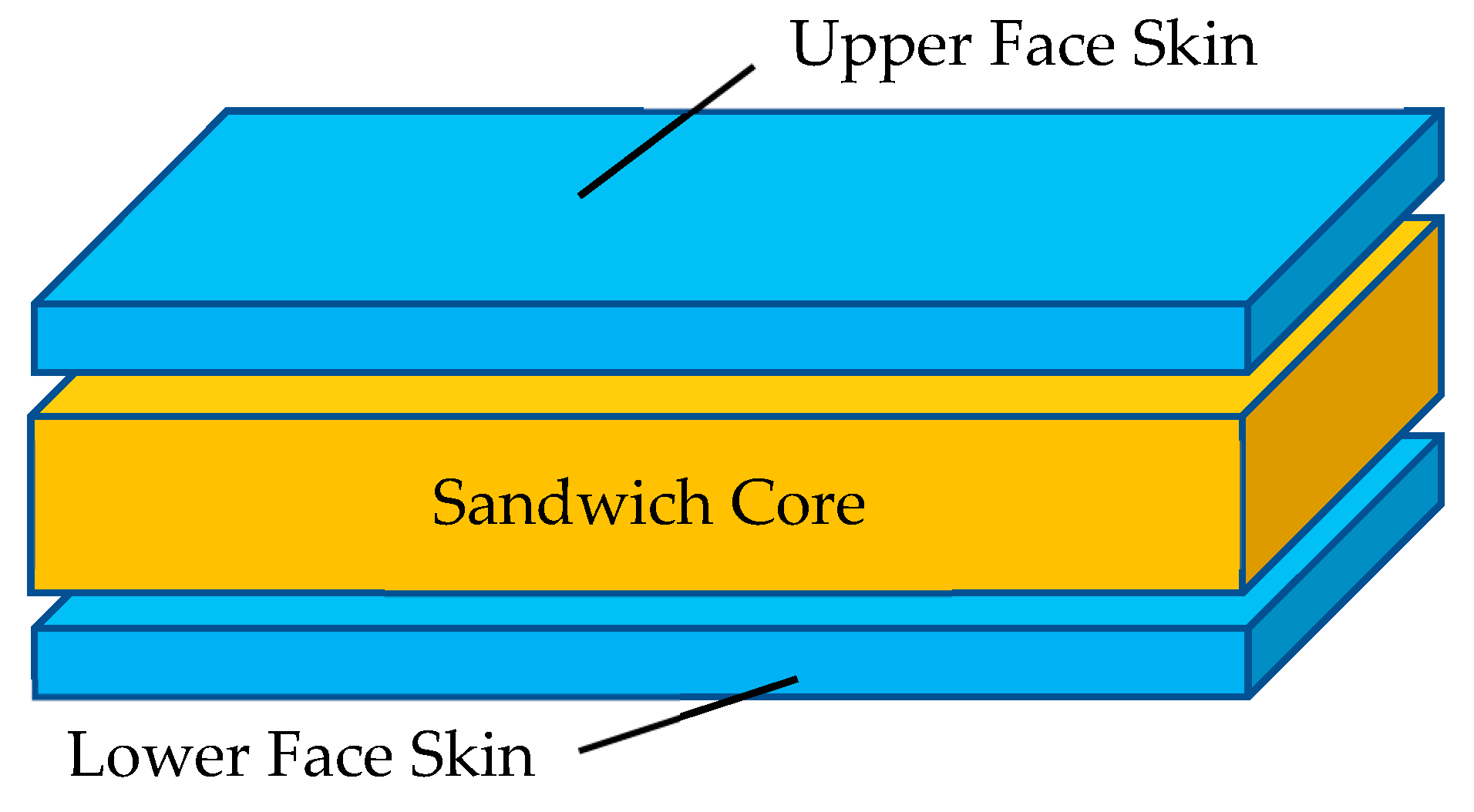
Figure 1. Schematic of a typical sandwich composite.
Buildings 12 01448 g001
Figure 2. Common manufacturing defect in composites.
Buildings 12 01448 g002
Figure 3. Two-dimensional model of the experimental setup.
Buildings 12 01448 g003
Figure 4. Face mesh for the defected case.
Buildings 12 01448 g004
Figure 5. Division of cases as per placement of inclusion.
Buildings 12 01448 g005
Figure 6. Pealing failure of the Nylforce glass fiber raft layer in the short sandwich beam was resolved by using paper tape.
Buildings 12 01448 g006
Figure 7. High flexible material droplets on the glass fiber layers due to the long standby time of the second nozzle.
Buildings 12 01448 g007
Figure 8. Inclusions at different locations and depths.
Buildings 12 01448 g008
Figure 9. Geometry characteristics of three-point bending of the beam.
Buildings 12 01448 g009
Figure 10. Sandwich panel standard nomenclature.
Buildings 12 01448 g010
Figure 11. Approximate bending stresses.
Buildings 12 01448 g011
Figure 12. Total deformation under point load for the intact case.
Buildings 12 01448 g012
Figure 13. Maximum principal stress (MAPS) distribution for the intact case.
Buildings 12 01448 g013
Figure 14. Maximum shear stress (MSS) distribution for the intact case.
Buildings 12 01448 g014
Figure 15. Normalized FE stresses along bonding lines L2 and L3.
Buildings 12 01448 g015
Figure 16. Load vs. displacement of the 3D-printed sandwich beam using experimental, theoretical, and FEA.
Buildings 12 01448 g016
Figure 17. MSS distribution along L3 of the beam length for Case 1.
Buildings 12 01448 g017
Figure 18. MSS distribution along L2 of the beam length for Case 1.
Buildings 12 01448 g018
Figure 19. MAPS distribution along L3 of the beam length for Case 1.
Buildings 12 01448 g019
Figure 20. MAPS distribution along L2 of the beam length for Case 1.
Buildings 12 01448 g020
Figure 21. MSS distribution along L3 defect radius R01, R03, and R05 for Case 2.
Buildings 12 01448 g021
Figure 22. MSS distribution along L2 for defect radius R01, R03, and R05 for Case 2.
Buildings 12 01448 g022
Figure 23. MAPS distribution along L3 for defect radius R01, R03, and R05 for Case 2.
Buildings 12 01448 g023
Figure 24. MAPS distribution along L2 for defect radius R01, R03, and R05 for Case 2.
Buildings 12 01448 g024
Figure 25. MSS distribution along L3 for E1, E2, and E3 of Case 3.
Buildings 12 01448 g025
Figure 26. MSS distribution along L2 for E1, E2, and E3 of Case 3.
Buildings 12 01448 g026
Figure 27. MAPS distribution along L3 for E1, E2, and E3 of Case 3.
Buildings 12 01448 g027
Figure 28. MAPS distribution along L2 for E1, E2, and E3 of Case 3.
Buildings 12 01448 g028
Table 1. Properties of the face and core materials.
PropertiesFace MaterialCore Material
Young’s Modulus1501 MPa26 MPa
Poison’s Ration0.30.3
Bulk Modulus1250.8 MPa21.66 MPa
Shear Modulus577.31 MPa10 MPa
Table 2. Range of operating parameters, its notations, and groups division.
Varying ParameterRangeNotationGroup
Group 1Group 2Group 3
Position of Inclusion0 mm Along L2C1, C_ circlePosition of inclusion variesRemains constantRemains constant
15 mmC3
50C5
0 mmAlong L3C2
15 mmC4
50C6
Geometry of Inclusion (Radius)0.1 mmR01, R_ RadiusRadius is constant at R03Radius (R) of inclusion variesRadius is constant at R03
0.3 mmR03
0.5 mmR05
Young’s modulus (E) of Inclusion0.26 MPaE1, E_ ModulusModulus is constant at E2Modulus is constant at E2Young’s modulus of inclusion varies
26 MPaE2
1051 MPaE3
Publisher’s Note: MDPI stays neutral with regard to jurisdictional claims in published maps and institutional affiliations.