Abstract
The structural analysis of historic masonry churches subject to earthquakes is commonly based on two distinct approaches: that of the global response to seismic actions and that of the local analysis of a priori pre-determined collapse mechanisms. This is a conventional decoupling of the structural problem due to the difficulty of addressing the seismic vulnerability of individual parts from the modelling of the whole. The aim of this work is to establish a link between the global behavior of the church and the assessment of the local mechanisms, re-evaluating the value of modal analysis to be associated with non-linear seismic assessment. With this aim, a two steps procedure is proposed, where: the first step is based on the detection of the main vibration modes of the whole building with identification of the structural bi-dimensional macro-elements that are responsible for the overall seismic vulnerability, while the second step, is based on the non-linear finite element analysis of the previously identified macro-elements, to evaluate the failure pattern caused by the earthquakes. The procedure will applied to the case study of the Casamari Gothic church in Veroli (Italy).
1. Introduction
Masonry churches represent a large portion of the European cultural heritage. This type of structures, designed to withstand only their self-weight, are highly vulnerable to seismic actions [1,2,3,4,5,6,7]. Since they are often located in high-risk seismic areas, the need to develop numerical tools that can describe their structural response to earthquakes is essential to estimate the cost and the extent of the safety interventions required to improve their seismic behavior.
According to the Italian Standard [8], the structural analysis of historic masonry buildings subject to earthquakes is commonly based on two distinct approaches: that of the global response to seismic actions and that of the local analysis of a priori pre-determined collapse mechanisms. This is a conventional decoupling of the structural problem due to the difficulty of addressing the seismic vulnerability of individual parts from the modelling of the whole.
While local analyses of a priori predetermined collapse mechanisms can be performed with conventional commercial tools based on analytical solutions, numerical modelling of the global response of masonry buildings subject to earthquakes is still an open task. Several numerical approaches can be adopted aiming at providing a correct description of the global response of masonry buildings: continuum models [9,10,11,12,13], block-based models [14,15,16,17,18] and equivalent frame models [19,20].
Equivalent frame models are certainly the most widely used in the case of regular buildings. On the other hand, the complex geometry of churches does not allow for the easy use of these models and consequently the analysis is often reduced to the assessment of local mechanisms only. Accordingly, the first two approaches mentioned are receiving increasing interest from the scientific community, as evidenced by the large number of scientific works on several case studies. Three-dimensional non-linear finite element analyses of masonry churches are presented in [21,22,23,24,25,26,27,28]. In [29], push over analyses of ancient masonry churches described by three-dimensional discrete element models are developed. In [5] the authors attempted to investigate the seismic behaviour of masonry churches by comparing the results from continuous and discrete three-dimensional models. In [30,31] a comparison between linear, non-linear dynamic analyses and an attept to adopt simplify equivalent beam models is presented. These latest works pave the way for a discussion on the importance of the dynamic response of the structure as a whole. The scientific community is divided on this topic. On the one hand, in fact, it is well known that linear models are inherently lacking since the linearity hypothesis is not satisfied for a material such as masonry, which is substantially not tensile resistant. Although, before the response becomes strongly non-linear, the distribution of seismic actions on the structure is essentially governed by the linear dynamic response. On the other hand, the analysis of collapse mechanisms disconnected from the rest does not properly account for the effects of dynamic amplification. Moreover, when the mechanism is not simply the overturing of the wall but includes a larger part of the monument (e.g., in the transversal response of the nave or in the longitudinal response of the colonnade) the mechanism cannot be easily defined a priori.
The authors tried to overcome the problems described above through a two steps procedure: (i) detection of the main vibration modes of the whole building with identification of the structural macro-elements that are responsible for the overall seismic vulnerability, (ii) non-linear finite element analyses of the previously identified macro-elements, to evaluate the failure pattern caused by the earthquakes.
The aim of this work is to establish a link between the global behavior of the church and the assessment of the local mechanisms, re-evaluating the value of modal analysis to be associated with non-linear seismic assessment. The first step of the procedure provides a reasonable estimate of the dynamic actions induced by the earthquake, the second step allows to carry out the structural assessment in the non-linear field with an acceptable computational burden.
This last step mainly requires the selection of a robust non-linear model capable of assessing seismic vulnerability. As a good compromise between accuracy and simplicity, masonry is described as an anisotropic elasto-plastic medium, whose yield criterion is derived via homogenisation [5,32]. In contrast to the more sophisticated material models available in the literature, which require a number of constitutive parameters that are often hardly available in current practice, the proposed model only requires a few parameters for its definition. Eventually, the decrease in strength is described taking into account the effect of the large displacements.
The present work investigates as a case study the seismic behaviour of the Casamari Gothic church inside the Casamari Abbey in Veroli (Italy). Firstly, historical research is conducted to improve the knowledge of structural behavior, the presence of retrofitting works made in the past and the identification of weak elements. The geometric survey is made in automatic way using Laser Scanner survey, in order to detect the complex three-dimensional geometry of the structure and any crack patterns. Then, the whole structure is analysed in the linear range by mean of a complete and refined 3D FE model. In order to validate the model, the results of the linear dynamic analysis are compared with those of the dynamic identification carried out in situ by the measurement of the ambient vibrations on the nave and bell tower of the church. Through the linear dynamic characterization of the structural response, the weak points of potential failure and, consequently, the macro-elements responsible for the overall seismic vulnerability are identified. The identified macro-elements are analysed in non-linear range with the aim of identifying the failure pattern responsible of the seismic behaviour of the whole building. Non-linear static analyses are developed on selected two-dimensional macro-elements subject to horizontal forces representing seismic actions. The analyses are carried out under conditions of constant gravitational loads and monotonically increasing horizontal loads. The distribution of applied horizontal forces is a modal pattern made of lateral forces consistent with the modal response analysis.
2. Case Study
2.1. Description of the Structure and Historical Research
The Gothic church of Casamari (Figure 1) is within the Abbey of Casamari which lies in the territory of Veroli (Frosinone) in central Italy, on a rocky hill at about 300 m above sea level. The Abbey, built in 1203 and consecrated in 1217, represents one of the most important examples of Cistercian Gothic architecture in Italy. According to the Italian Standard, the area where the church is located is a medium seismic hazard zone where strong earthquakes with value up to 0.20 g can occur.
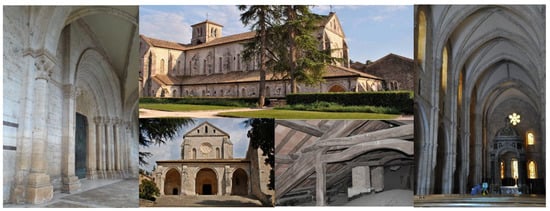
Figure 1.
The Casamari Gothic church: church façade, an interior view and details of timber roof.
2.2. Geometry and Materials
The plan view of the church (Figure 2) shows a typical three-nave plan. The nave, 61.3 m wide and 10.9 m long, has walls ranging from 1 to 1.4 m thick. The masonry is made of squared stone blocks with lime mortar joints, while solid brick columns support the wooden roof (Figure 1). Since a mechanical characterisation of the materials was not available, the constitutive parameters of the masonry were taken from the Italian Standard [8], (Table 1).
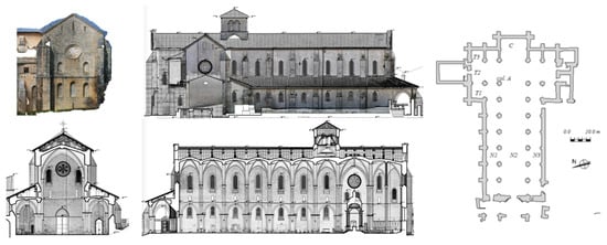
Figure 2.
Views of the church.

Table 1.
Mechanical characteristics of masonry and timber.
3. 3D Model
3.1. FE Model
A three-dimensional finite element model of the whole church was constructed using shell elements to describe the mean plane of the masonry walls and vaults, while the wooden roof structures were discretized by truss and beam elements.
The three-dimensional model was built through the Laser Scanner survey (Figure 3), a cloud constituted by approximately 2.5 million points has then been post-processed and used to define the finite element model. The mean plane of each vertical wall was drawn from the point cloud (Figure 4). Figure 4 shows the plan layout of the church regularized to locate the extent and the interaction of the mean plane of the vertical walls with the adjacent ones.
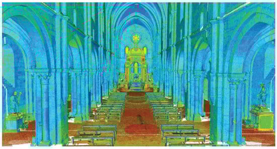
Figure 3.
Interior view of the church from point cloud.
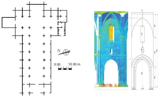
Figure 4.
Regularized plan layout of the church (on the left) and drawing geometry from the point cloud (on the right).
The finite element model consists of 55,529 shell elements and 1785 1D elements for a total of 34,849 nodes (Figure 5). The horizontal and vertical displacements of all nodes at ground level were constrained. The masonry was modelled as an isotropic linear elastic continuum, described by adopting the parameters of Table 1.
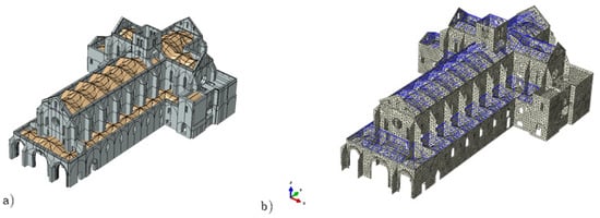
Figure 5.
Three-dimensional model of the church: (a) geometrical model and (b) finite element model.
A preliminary analysys of the church under self-weight was carried out. The total weight of the church is approximately 213,026 kN. Under this load, the materials work in the elastic field and the maximun value of the compressive stress, reached at the bases of the columns under the bell tower, is about 2.6 MPa. This value is lower than the compressive strenght of the material (6–8 MPa).
3.2. Linear Dynamic Analysis
Table 2 summarises the results, in terms of frequencies and participanting mass of the first 9 modal shapes, of the linear dynamic analysis performed on the three-dimensional model of the church. The first modal form, which corresponds to a frequency of 3.0686 Hz with a participating mass of 42.2%, affects the entire structure in the transverse direction (Figure 6a). The second modal shape, with a frequency of 3.0686 Hz and a participating mass of 53.4%, involves the entire structure in the longitudinal direction (Figure 6b). The third modal shape (Figure 6c), with a frequency of 3.9997 Hz, shows torsional deformations, revealing some cooperation between the transverse and longitudinal structural elements. The upper modal shapes are a combination of transverse, longitudinal and torsional vibration modes. Similar results were presented in [33], where the responce to seismic load of the Gothic church of Fossanova was analysed.
Table 2.
Modal frequencies and partecipating masses.
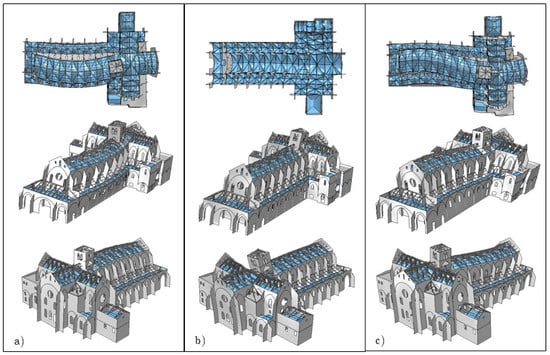
Figure 6.
(a) First, (b) second and (c) third modal shapes.
The sum of the participating mass of the first 9 eigen-modes was 54.3% and 55.4% of the total mass in the transverse and longitudinal directions, respectively (Table 2). It was necessary to consider the first 100 modes to obtain a total participating mass greater than 80% of the total mass [22,34].
3.3. Dynamic Identification
In order to validate the finite element model in term of geometry and stiffness, the ambient vibrations of the church were measured both on the nave and bell tower. The measurements were performed using six independent integrated instruments composed by a biaxial force-balance accelerometer, with measurement range from 1 μg to 0.5 g in the frequency band (0 Hz 100 Hz), and a 24 bit Analogical-to-Digital converter. Each instrument was completed by a memory card for data storage, a GPS receiver for the synchronisation of recorded signals with Coordinated Universal Time (UTC) and, eventually, a wireless connection for remote control of the instrument and data download. The accelerometers were arranged according to the two configurations of Figure 7. In the first one the accelerometers were positioned for monitoring two different levels of the bell tower. In the second configuration four accelerometers were positioned on the 1st, the 3rd, the 6th and the 9th keystones, one was positioned inside the nave (10 m above the floor level). It is importan to note that two accelerometers were left in the same position they had in the first configuration, so allowing us to combine partial mode shape of individual configurations in an overall global mode shape. Ambient vibrations of 1800 s, with a sampling frequency of 200 Hz, was recorded for each configuration.
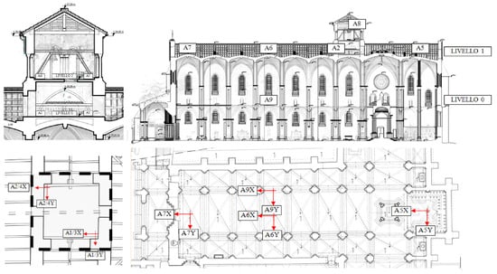
Figure 7.
Accelerometers layout: configuration 1 (left) and configuration 2 (right).
The dynamic identification was carried out through “LMS-Test.Lab Operational Modal Analysis©” (OMA), by Siemens PLM software. The PolyMAX algorithm [35] was used for modal parameters extraction. In this kind of approach, in order to distinguish structural modes from numerical ones or possible spurious harmonic components, mathematical models of increasing order are applied to the cross-spectra so that the actual modal parameters are selected, using the “stabilization diagram”, among the poles which result to be stable as the model order is increased. Three global mode of the church was identified at frequencies 3.36 Hz (transversal mode), 4.31 Hz (longitudinal mode) and 4.53 Hz (torsional mode).
3.4. Comparison and Validation
The three global modes identified by Operational Modal Analysis (OMA) were compared with the numerical results of the linear dynamic analysis carried out with the finite element model, using the Modal Assurance Criterion (MAC) [36] and the frequency percentage difference between the frequencies obtained by OMA and FEM. The results of this comparison is shown in Table 3. Finally, in Figure 8 the OMA and the FEM mode shapes are graphically compared component by component. We observe that there is a good agreement between the FEM mode shapes and the OMA ones, in fact the MAC of modes 1 and 2 are very close to 1, values corresponding to a perfect coincidence of the two vectors, while in the case of the third mode, the value is still close to 0.9. From Table 3 it can be also observed that all natural frequencies of the FEM () are lower then the experimental ones () of 2–5%. However, because, also in the case of a weak earthquake, the frequencies governing the seismic behaviour of a masonry structure are in general lower than the frequencies identified from ambient vibrations [37,38], there would be no advantage for our ability to predict the actual seismic behaviour of the church, in calibrating the FEM to make its frequencies closer to the experimental ones.
Table 3.
Comparison of numerical and experimental modal parameters.
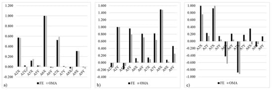
Figure 8.
Comparison between FEM and Operational Modal Analysis (OMA): (a) Mode shape 1, (b) Mode shape 2 and (c) Mode shape 3.
4. Non-Linear Analyses of the Macro-Elements
4.1. Identification of the Two-Dimensional Macro-Elements
Despite the fact that the three-dimensional model of the whole church was already been constructed, it was decided to perform the non-linear analyses only on selected two-dimensional macro-elements in order to reduce the computational cost related to the non-linear analyses.
Two 2D macro-elements were selected by analysing the portion of the building involved in the first and the second modal shapes. In Figure 9, the plan layout of the church with the selected macro-elements is represented: the macro-element T and the macro-element L. In the upper part of the same Figure 9, a section of the the first and the second modal shapes in correspondence of the selected macro-elements, is also reported.
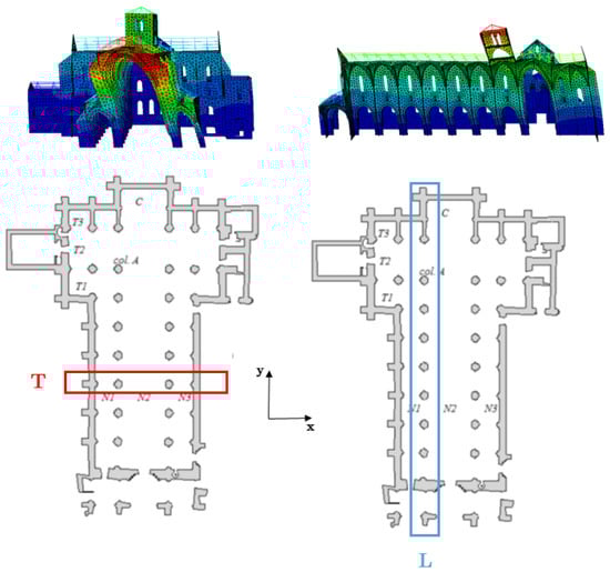
Figure 9.
Selected two-dimensional macro-elements.
The two selected two-dimensional macro-elements of the church were pushed with horizontal forces. The analyses were carried out under conditions of constant gravitational loads and monotonically increasing horizontal loads.
The horizontal load distribution adopted is made of lateral forces consistent with the first modal shape of the three-dimensional model for the T macro-element and with the second modal shape of the three-dimensional model for the L macro-element. In order to compare the numerical results with each other, an additional horizontal load distribution will be adopted consisting of lateral forces proportional to the masses regardless of their position in the structure.
4.2. Finite Element Model of the Macro-Elements
The two-dimensional finite element models of the two selected macro-elements were constructed from the three-dimensional model by extrapolating the portion of the structure corresponding to the macro-elements in question. The models are discretized with six-node triangular elements under plane state conditions and the material is modified with respect to the three-dimensional model by introducing non-linearity parameters.
The non-linear behaviour of masonry was modelled by means of the constitutive law proposed in [32]. According to it, masonry walls are represented as homogenised elasto-plastic solids in a two-dimensional plane state, with an associated flow rule. The elastic domain , defined in the context of perfect multi-surface plasticity, consists of four planes that can be written in terms of the stress components in the reference (axes parallel to the bed and head mortar joints), as follows:
is the aspect ratio height-to-width of the blocks and is the friction angle. The two following planes are added to the domain to assign a finite strength in compression to the masonry:
whit and the compressive strengths in the two directions and .
The model has been implemented in a FE code to carry step by step analyses of structures subject to external loads. The same model has been adopted for the solution of several problems: soil-structure interaction [39], collapse mechanism analysis under horizontal forces [5,40] and effect of settlements [41,42].
T and L Macro-Element
The two-dimensional section shown in Figure 10, T macro-element, consists of a portion of wall about 19.2 m long and 25.5 m high. It is made up of a central arch, section of the vaults along the main nave, and two smaller side arches, section of vaults of side aisles naves. The section also consist of four circular columns, the two larger central ones and the two smaller lateral ones. The finite element model was built with 8511 triangular elements.
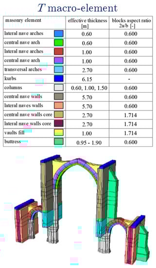
Figure 10.
T macro-element.
The two-dimensional section shown in Figure 11, L macro-element, consists of a portion of wall about 72 m long and 18.6 m high. The large arch of about 7.0 m in width and 17.0 m in height represents a section of the vault at the transept. At the left of the transept, a sequence of eight arches is visible in the lower part and a sequence of seven openings in the upper part. At the right of the transept, the wall is massive with small openings (Figure 11). The section was discretised by mean of 49,259 triangular elements.
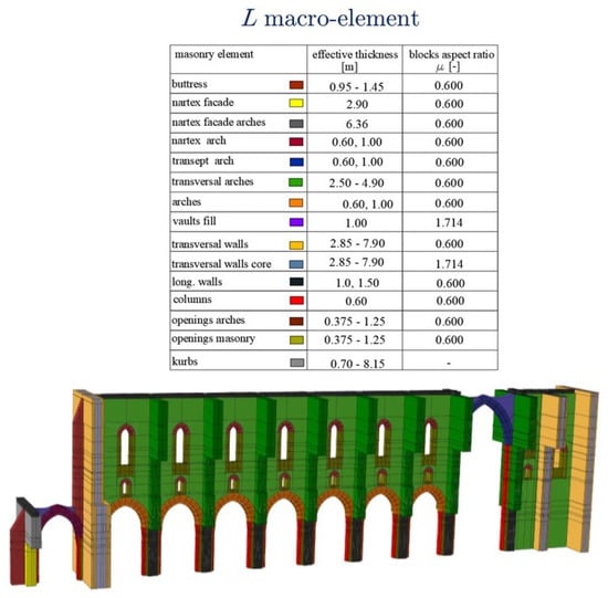
Figure 11.
L macro-element.
For both the macro-elements, the horizontal and vertical displacements at all the nodes at ground level were restrained while the presence of roofing wooden elements was neglected, to evoid complex non-linear model of the masonry-wooden connections.
In Figure 10 and Figure 11, the mechanical and the geometrical parameters of the masonry are shown, too. The value of the aspect ratio was evaluated through direct observation of the masonry texture. Several aspect ratios were introduced to describe the different behaviour of the elements (masony and infill). Finally, the friction angle was assumed to be 0.54 rad.
4.3. Pushover Analysis
4.3.1. T Macro Element
In Figure 12 the results of the push-over analysis under modal load pattern, are represented in terms of the distribution of the maximum plastic strains on the section at failure.
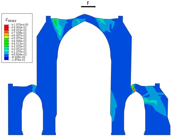
Figure 12.
T macro-element: distribution of the maximum plastic strains.
The section pushed in the horizontal direction, shows a concentration of plastic strains, corresponding to the opening of the mortar joints, mainly on the small arch of the right aisle and on the central arch. This distribution of plastic strains provide infomation on the development of the failure mechanism involving the main nave and one side aisle, in agreeent with the failure mechanism found in the scientific literature [33,43].
In Figure 13, the capacity curve in term of shear at the basis versus the control point displacement is shown. The key node of the central arch was adopted as the control point. The first plastic hinge develops at the arch of the side aisle, for a low load level (a sudden change in the slope of the capacity curves can be observed). The reduction of the load carry capacity after the peak, at which all plastic hinges have already developed, is due only to the effect of large displacements. The displacement capacity of the section is equal to about 60 cm.
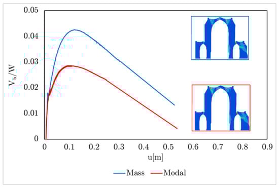
Figure 13.
T macro-element: capacity curves.
In the same figure, the capacity curve obtained pushing the macro-element with horizontal forces proportional to the masses, is represented. As expected, the horizontal loading consistent with the modal shape results in a lower capacity of the structure, due to the concentration of forces to the highest part of the macro-element. However the damage distribution was similar for both the load configurations.
4.3.2. L Macro-Element
The modal load pattern was also adopted in the numerical analyses concerning the macro-element L. Since the section was not symmetrical, the positive and the negative directions for the horizontal forces were considered.
Figure 14 shows the distribution of the maximum plastic strains in the case of the section pushed in the positive (a) and negative (b) direction. Concerning the positive loading direction, the part of the section mainly involved in the failure is the one adjacent to the transept where a strong concentration of plastic strains is observed. The same result is found in other similar case studies [44]. Further, diagonal failure patterns are observed above almost all the openings.
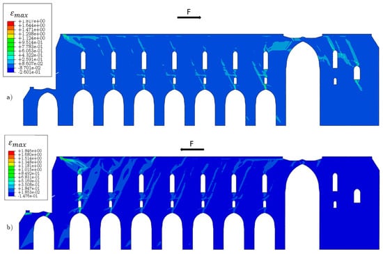
Figure 14.
L macro-element: distribution of the maximum plastic strains for (a) positive direction of the load and (b) negative direction of the load.
If negative horizontal forces direction (Figure 14b) is considered, the parts of the structure mainly involved into the collapse are the one adjacent to the façade and the arch of the portico. Further, a diagonal failure pattern between almost all the openings can also shown.
In Figure 15, the capacity curves for the two different loading directions are shown. In the same Figure 15, the curves obtained pushing the macro-element with horizontal forces proportional to the masses are also represented, for both the directions, positive and negative. As for the previous section, the horizontal loading consistent with the modal shape results in a lower capacity of the structure.
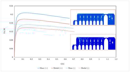
Figure 15.
L macro-element: capacity curves.
Regarding the choice of the control point, the average displacement of several nodes at the top of the L macro-element [45] was adopted: the displacements were computed at all the points for each step and the average value was considered. Also for these analyses, the reduction in load carry capacity is due to the effect of large displacements. Due to the ductility of the section, the displacement capacity results in a too large value. However, the collpase mechanichs obtained by the numerical analyses provide info about the portion of the structure, not a priori pre-determined, involved in a local mechanism.
5. Conclusions
The authors proposed a simplified integrated approach to study the seismic behaviour of ancient masonry churches, from historical research up to the non-linear finite element analyses. The work highlighted: the relevance of the geometric survey of the building using Laser Scanner techniques, as a fundamental knowledge basis for the construction of the finite element model; the possibility of using dynamic identification techniques to appropriately calibrate the masonry properties in terms of stiffness and thus validate the results of the modal analysis; the use of modal analysis to define the horizontal load profile to be attributed to the collapse mechanisms; the need for non-linear constitutive models for seismic assessment in which the collapse mechanism is not prefigured a priori but is derived from the analyses.
In the case of a church with a typical basilica plan, as the Casamari church, the results of the modal analysis highlighted the possibility to select two 2D macro-elements able to synthetise the main vulnerabilities of the structure under earthquake. Non-linear static analyses were carried out on the two selected macro-elements showing that several parts of the church are significantly exposed to damage under earthquake. With reference to the case of study, the most critical elements are: the transverse arches of the nave and the aisles that could exhibit a local failure mechanism, the façade that could collpase with out of plane overturning and the transept arch.
It is important to observe that the analysis presented in this work should be extended in order to contemplate in more detail the collapse of other elements, for example the macro-element including the bell tower could be selected.
Author Contributions
Conceptualization, M.M. and G.d.F.; Data curation, A.G., B.P. and D.S.; Formal analysis, M.M., A.G., B.P. and D.S.; Methodology, M.M. and G.d.F.; Writing—original draft, M.M. and D.S.; Writing—review & editing, M.M. and G.d.F. All authors have read and agreed to the published version of the manuscript.
Funding
This research was funded by the Italian Q6 Ministry of Education, University and Research (MIUR) under Q17 the Departments of Excellence grant number L.232/2016.
Data Availability Statement
Not applicable.
Acknowledgments
The financial support of Consortium ‘ReLUIS-Italian Department of Civil Protection’ (ReLUIS-DPC 2019-2021 Projects), Research Line Masonry structures is acknowledged. The Authors gratefully acknowledges financial support from the Italian Ministry of Education, University and Research (MIUR) under the Departments of Excellence grant L..
Conflicts of Interest
The authors declare no conflict of interest.
References
- de Felice, G.; Fugger, R.; Gobbin, F. Overturning of the façade in single-nave churches under seismic loading. Bull. Earthq. Eng. 2022, 20, 941–962. [Google Scholar] [CrossRef]
- Clementi, F. Failure Analysis of Apennine Masonry Churches Severely Damaged during the 2016 Central Italy Seismic Sequence. Buildings 2021, 11, 58. [Google Scholar] [CrossRef]
- Fazzi, E.; Galassi, S.; Misseri, G.; Rovero, L. Seismic vulnerability assessment of the benedictine basilica typology in central Italy. J. Build. Eng. 2021, 43, 02897. [Google Scholar] [CrossRef]
- Cescatti, E.; Salzano, P.; Casapulla, C.; Ceroni, F.; da Porto, F.; Prota, A. Damages to masonry churches after 2016–2017 Central Italy seismic sequence and definition of fragility curves. Bull. Earthq. Eng. 2020, 18, 297–329. [Google Scholar] [CrossRef]
- Malena, M.; Portioli, F.; Gagliardo, R.; Tomaselli, G.; Cascini, L.; de Felice, G. Collapse mechanism analysis of historic masonry structures subjected to lateral loads: A comparison between continuous and discrete models. Comput. Struct. 2019, 220, 14–31. [Google Scholar] [CrossRef]
- Lagomarsino, S. Damage assessment of churches after L’Aquila earthquake (2009). Bull. Earthq. Eng. 2012, 10, 73–92. [Google Scholar] [CrossRef]
- Lourenço, P.B.; Krakowiak, K.J.; Fernandes, F.M.; Ramos, L.F. Failure analysis of Monastery of Jeronimos, Lisbon: How to learn from sophisticated numerical models. Eng. Fail. Anal. 2007, 14, 280–300. [Google Scholar] [CrossRef]
- NTC-2018, Decreto Ministeriale 17/1/2018. Nuove Norme Tecniche per le Costruzioni (In Italian); Ministry of Infrastructures and Transportations: Rome, Italy, 2018.
- Gambarotta, L.; Lagomarsino, S. Damage models for the seismic response of brick masonry shear walls. Part II: The continuum model and its applications. Earthq. Eng. Struct. Dyn. 1997, 26, 441–462. [Google Scholar] [CrossRef]
- Berto, L.; Saetta, A.; Scotta, R.; Vitaliani, R. An orthotropic damage model for masonry structures. Int. J. Numer. Methods Eng. 2002, 55, 127–157. [Google Scholar] [CrossRef]
- Milani, G.; Lourenço, P.B.; Tralli, A. 3D homogenized limit analysis of masonry buildings under horizontal loads. Eng. Struct. 2007, 29, 3134–3148. [Google Scholar] [CrossRef] [Green Version]
- Brasile, S.; Casciaro, R.; Formica, G. Multilevel approach for brick masonry walls-part I: A numerical strategy for the nonlinear analysis. Comput. Methods Appl. Mech. Eng. 2007, 196, 4934–4951. [Google Scholar] [CrossRef]
- Pelà, L.; Cervera, M.; Roca, P. An orthotropic damage model for the analysis of masonry structures. Constr. Build. Mater. 2013, 41, 957–967. [Google Scholar] [CrossRef]
- Portioli, F.; Casapulla, C.; Gilbert, M.; Cascini, L. Limit analysis of 3D masonry block structures with non-associative frictional joints using cone programming. Comput. Struct. 2014, 143, 108–121. [Google Scholar] [CrossRef]
- Çaktı, E.; Saygılı, Ö.; Lemos, J.V.; Oliveira, C.S. Discrete element modeling of a scaled masonry structure and its validation. Eng. Struct. 2016, 126, 224–236. [Google Scholar] [CrossRef]
- Serpieri, R.; Albarella, M.; Sacco, E. A 3D microstructured cohesive-frictional interface model and its rational calibration for the analysis of masonry panels. Int. J. Solids Struct. 2017, 122, 110–127. [Google Scholar] [CrossRef]
- Baraldi, D.; Cecchi, A. A full 3D rigid block model for the collapse behaviour of masonry walls. Eur. J. Mech.-A Solids 2017, 64, 11–28. [Google Scholar] [CrossRef]
- D’Altri, A.M.; Castellazzi, G.; de Miranda, S. Collapse investigation of the Arquata del Tronto medieval fortress after the 2016 Central Italy seismic sequence. J. Build. Eng. 2018, 18, 245–251. [Google Scholar] [CrossRef]
- Caliò, I.; Marletta, M.; Pantò, B. A new discrete element model for the evaluation of the seismic behaviour of unreinforced masonry buildings. Eng. Struct. 2012, 40, 327–338. [Google Scholar] [CrossRef]
- Cattari, S.; D’Altri, A.M.; Camilletti, D.; Lagomarsino, S. Equivalent frame idealization of walls with irregular openings in masonry buildings. Eng. Struct. 2022, 256, 114055. [Google Scholar] [CrossRef]
- Romera, L.E.; Hernandez, S.; Reinosa, J.M. Numerical characterization of the structural behaviour of the Basilica of Pilar in Zaragoza (Spain). Part 1: Global and local models. Adv. Eng. Softw. 2008, 39, 301–314. [Google Scholar] [CrossRef]
- Betti, M.; Vignoli, A. Numerical assessment of the static and seismic behaviour of the basilica of Santa Maria all’Impruneta. Constr. Build. Mater. 2011, 25, 4308–4324. [Google Scholar] [CrossRef]
- Milani, G.; Valente, M. Comparative pushover and limit analyses on seven masonry churches damaged by the 2012 Emilia-Romagna (Italy) seismic events: Possibilities of non-linear finite elements compared with pre-assigned failure mechanisms. Eng. Fail. Anal. 2015, 47, 129–161. [Google Scholar] [CrossRef]
- Manos, G.C.; Kotoulas, L.; Kozikopoulos, E. Evaluation of the Performance of Unreinforced Stone Masonry Greek “Basilica” Churches When Subjected to Seismic Forces and Foundation Settlement. Buildings 2019, 9, 106. [Google Scholar] [CrossRef]
- Soulis, V.J.; Manos, G.C. Numerical Simulation and Failure Analysis of St. Konstantinos Church after the Kozani Earthquake. Int. J. Civ. Eng. 2019, 17, 949–967. [Google Scholar] [CrossRef]
- Fortunato, G.; Funari, M.F.; Lonetti, P. Survey and seismic vulnerability assessment of the baptistery of san giovanni in tumba (Italy). J. Cult. Herit. 2017, 26, 64–78. [Google Scholar] [CrossRef]
- Zizi, M.; Corlito, V.; Lourenço, P.B.; De Matteis, G. Seismic vulnerability of masonry churches in Abruzzi region, Italy. Structures 2021, 32, 662–680. [Google Scholar] [CrossRef]
- Brando, G.; Criber, E.; De Matteis, G. The effects of L’aquila earthquake on the St. Gemma church in Goriano Sicoli: Part II—Fem analysis. Bull. Earthq. Eng. 2015, 13, 3733–3748. [Google Scholar] [CrossRef]
- Pantó, B.; Cannizzaro, F.; Caddemi, S.; Calió, I. 3D macroelement modelling approach for seismic assessment of historical masonry churches. Adv. Eng. Softw. 2016, 97, 40–59. [Google Scholar] [CrossRef]
- Formisano, A.; Vaiano, G.; Fabbrocino, F.; Milani, G. Seismic vulnerability of Italian masonry churches The case of the Nativity of Blessed Virgin Mary in Stellata of Bondeno. J. Build. Eng. 2018, 20, 179–200. [Google Scholar] [CrossRef]
- Clementi, F.; Gazzani, V.; Poiani, M.; Lenci, S. Assessment of seismic behaviour of heritage masonry buildings using numerical modelling. J. Build. Eng. 2016, 8, 29–47. [Google Scholar] [CrossRef]
- de Felice, G.; Amorosi, G.; Malena, G. Elasto-plastic analysis of block structures through a homogenization method. Int. J. Numer. Anal. Meth. Geomech. 2012, 34, 221–247. [Google Scholar] [CrossRef]
- De Matteis, G.; Mazzolani, F.M. The Fossanova church: Seismic vulnerability assessment by numeric and physical testing. Int. J. Archit. Herit. 2010, 4, 222–245. [Google Scholar] [CrossRef]
- Brandonisio, G.; Lucibello, G.; Mele, E.; De Luca, A. Damage and performance evaluation of masonry churches in the 2009 L’aquila earthquake. Eng. Fail. Anal. 2013, 34, 693–714. [Google Scholar] [CrossRef]
- Peeters, B.; Van der Auweraer, H. PolyMAX: A revolution in Operational Modal Analysis. In Proceedings of the 1st IOMAC, Copenhagen, Denmark, 26–27 April 2005. [Google Scholar]
- Ewins, D.J. Modal Testing: Theory, Practice and Application; Research Studies Press Ltd.: Hertfordshire, UK, 2000. [Google Scholar]
- Gueguen, P. Seismic Vulnerability of Structures; John Wiley and Son Ltd.: Croydon, UK, 2013. [Google Scholar]
- Mori, F.; Acunzo, G.; Fiorini, N.; Pagliaroli, A.; Spina, D.; Dolce, M. La metodologia SMAV (Seismic Model from Ambient Vibrations) per la valutazione dell’operatività strutturale degli edifici esistenti. In Proceedings of the ANIDIS, L’Aquila, Italy, 13–17 September 2015. [Google Scholar]
- Amorosi, A.; Boldini, D.; de Felice, G.; Malena, M. Tunnelling-induced deformation on a masonry structure: A numerical approach. In Geotechnical Aspects of Underground Construction in Soft Ground; CRC Press: London, UK, 2012; pp. 353–359. [Google Scholar]
- de Felice, G.; Malena, M. Failure pattern prediction in masonry. J. Mech. Mater. Struct. 2019, 14, 663–682. [Google Scholar] [CrossRef]
- Landolfo, R.; Gagliardo, R.; Cascini, L.; Portioli, F.; Malena, M.; Tomaselli, G.; de Felice, G. Rigid block and finite element analysis of settlement-induced failure mechanisms in historic masonry walls. Frat. Integrita Strutt. 2020, 14, 517–533. [Google Scholar]
- Malena, M.; Angelillo, M.; Fortunato, A.; de Felice, G.; Mascolo, I. Arch bridges subject to pier settlements: Continuous vs. piecewise rigid displacement methods. Meccanica 2021, 56, 2487–2505. [Google Scholar] [CrossRef]
- Saloustros, S.; Pelà, L.; Roca, P.; Portal, J. Numerical analysis of structural damage in the church of the Poblet Monastery. Eng. Fail. Anal. 2015, 48, 41–61. [Google Scholar] [CrossRef]
- Gattulli, V.; Antonacci, E.; Vestroni, F. Field observations and failure analysis of the Basilica S. Maria di Collemaggio after the 2009 L’Aquila earthquake. Eng. Fail. Anal. 2013, 34, 715–734. [Google Scholar] [CrossRef]
- Lagomarsino, S.; Cattari, S. PERPETUATE guidelines fo seismic performance-based assessment of cultural heritage masonry structures. Bull. Earthq. Eng. 2015, 13, 13–47. [Google Scholar] [CrossRef]
Publisher’s Note: MDPI stays neutral with regard to jurisdictional claims in published maps and institutional affiliations. |
© 2022 by the authors. Licensee MDPI, Basel, Switzerland. This article is an open access article distributed under the terms and conditions of the Creative Commons Attribution (CC BY) license (https://creativecommons.org/licenses/by/4.0/).