


Design Model of Rectangular Concrete-Filled Steel Tubular Stub Columns under Axial Compression
 , , and
Abstract
:1. Introduction
2. Summary of the Test Database
- The columns considered must be tested under static axial compression loads.
- The columns must have square or rectangular single-skin cross-sections.
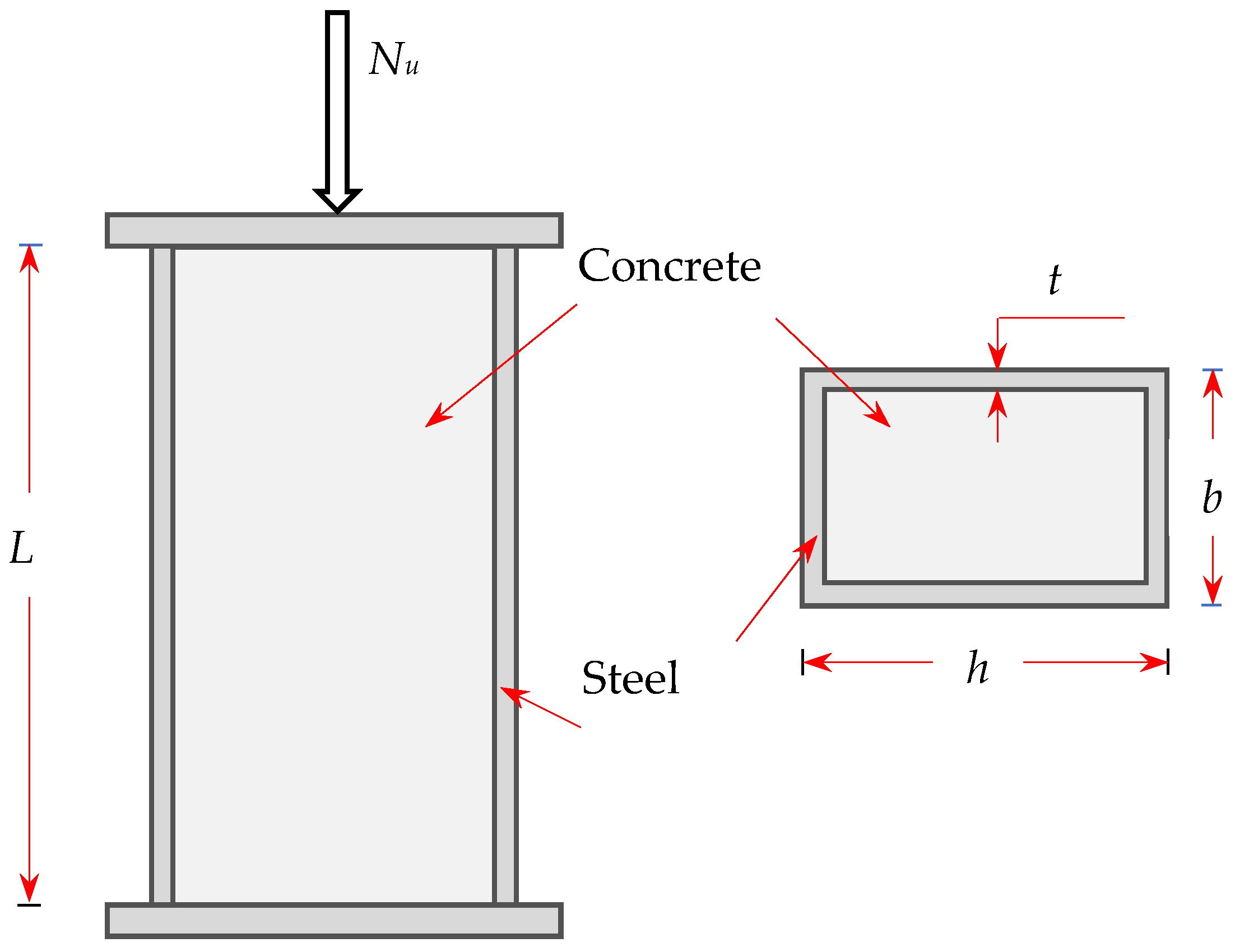
- The concrete core and the steel tube must be loaded simultaneously, as illustrated in Figure 1.
- The column specimens were checked to ensure that they can be classified as short columns according to the EC4 in which L/b ≤ 4; where L is the specimen length and b is the section width [22].
- Irrelevant CFST columns made of different materials such as stainless steel or aluminum were excluded.
- The columns should not have internal steel reinforcements, shear connectors, or any types of stiffeners, etc.
3. Formulations of Current Design Codes
3.1. ACI Approach
3.2. EC4 Approach
3.3. BS5400 Approach
3.4. DBJ13-51 Approach
3.5. Limitations of Current Design Codes
3.6. Comparative Studies
4. New Design Models
4.1. The First Proposal to Modify the Existing Design Formulas
- The equations must epitomize the experimental data as much as possible.
- The expressions have to be similar to the existing expressions provided by the standards.
- The formulae should be as simple as possible.
Comparative Studies
4.2. The Second Proposal to Modify the Existing Design Formulas
Comparative Studies
5. Conclusions
- Despite the considerable number of experimental tests on CFST stub columns, it was found that fewer tests were performed on columns made using high-strength materials. In addition, the tests on large-scale columns were very limited and the majority of these tests were focused on CFST stub columns with small cross-sections.
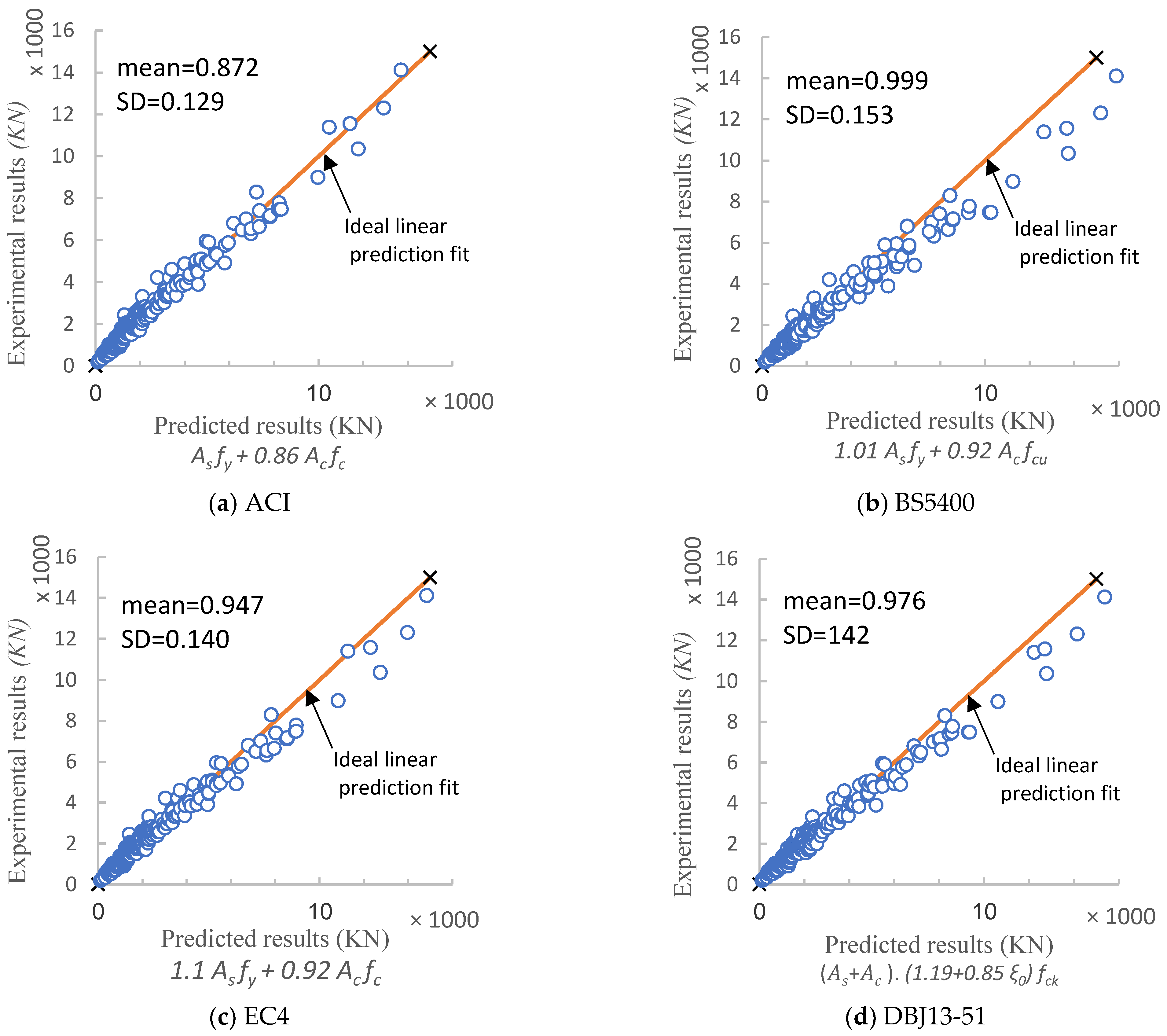
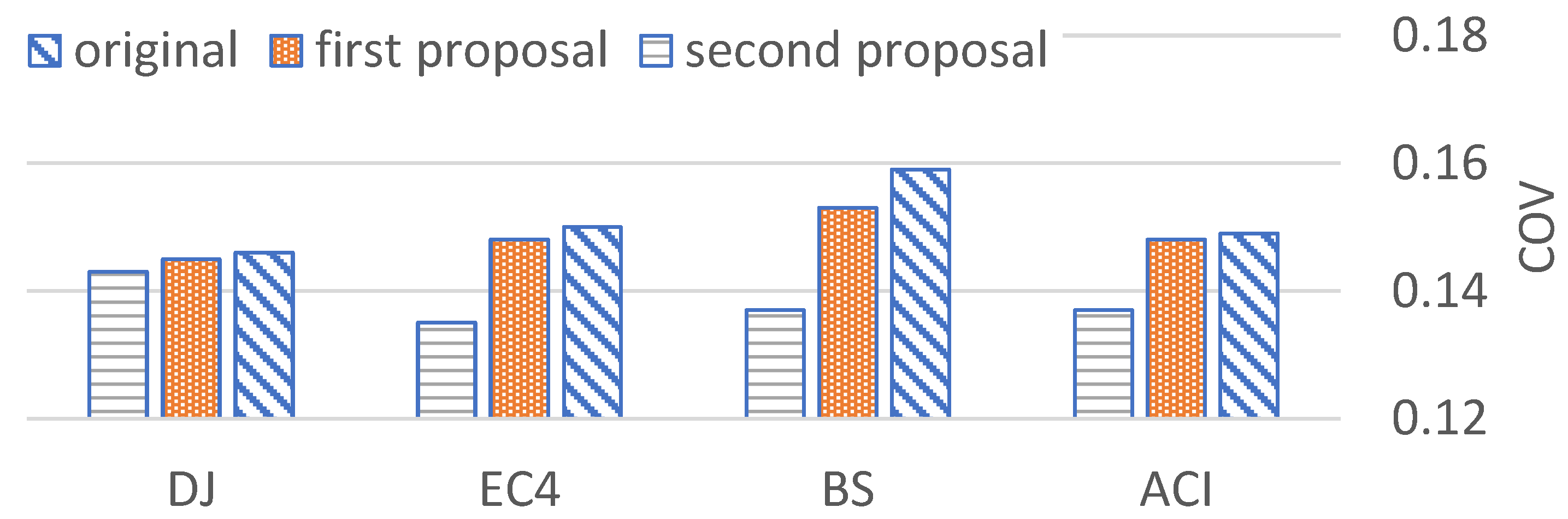
- All four codes provided a conservative prediction of CFST stub columns. The Chinese Standard (DBJ13-51) approach gave the most reliable mean value of the predicted load-carrying capacity to experimental results, while the best scatter was achieved by the ACI approach.
- Better predictions have been generally achieved using the first modified equations of the CFST load-carrying capacity than that of the original four codes. The modified formula based on the BS5400 approach gave the most precise results. However, it was found that the first proposed equations mainly provide accurate predictions for small sectional capacities, while the scattering of the results increases with the increase in section resistance.
- To improve the scatter of the results, other proposed equations were introduced. It was found that this second proposed approach can provide the most precise results compared to the existing and the first proposed formulas, especially the equation derived from the BS5400 code with a coefficient of variation (COV) of 0.1371.
Author Contributions
Funding
Data Availability Statement
Conflicts of Interest
Appendix A. Specimen Database

| No | Name of Specimens | b (mm) | h (mm) | t (mm) | fy (MPa) | f′c (MPa) | L (mm) | Nu (KN) | Tested by |
|---|---|---|---|---|---|---|---|---|---|
| 1 | 1 | 142.1 | 142.1 | 3.02 | 255.1 | 49.2 | 426.3 | 1360 | Zhang et al., 2005 [16] |
| 2 | 2 | 142.1 | 142.1 | 3.02 | 255.1 | 49.2 | 426.3 | 1400 | |
| 3 | 3 | 143.1 | 143.1 | 3.02 | 255.1 | 49.2 | 429.3 | 1150 | |
| 4 | 4 | 101.3 | 101.3 | 4.97 | 347.3 | 54.2 | 303.9 | 1310 | |
| 5 | 5 | 103.6 | 103.6 | 4.9 | 347.3 | 54.2 | 310.8 | 1340 | |
| 6 | 6 | 102 | 102 | 4.97 | 347.3 | 54.2 | 306 | 1370 | |
| 7 | 7 | 142 | 142 | 5.11 | 347.3 | 54.2 | 426 | 2160 | |
| 8 | 8 | 142 | 142 | 5.08 | 347.3 | 54.2 | 426 | 2250 | |
| 9 | 9 | 141.4 | 141.4 | 5.07 | 347.3 | 54.2 | 424.2 | 2280 | |
| 10 | 10 | 141.5 | 141.5 | 3.08 | 255.1 | 66.2 | 424.5 | 1920 | |
| 11 | 11 | 142.4 | 142.4 | 3.05 | 255.1 | 66.2 | 427.2 | 2060 | |
| 12 | 12 | 141.6 | 141.6 | 3.04 | 255.1 | 66.2 | 424.8 | 1960 | |
| 13 | 13 | 103.5 | 103.5 | 5.01 | 347.3 | 66.2 | 310.5 | 1500 | |
| 14 | 14 | 102.1 | 102.1 | 4.97 | 347.3 | 66.2 | 306.3 | 1330 | |
| 15 | 15 | 101.9 | 101.9 | 5.03 | 347.3 | 66.2 | 305.7 | 1440 | |
| 16 | 16 | 142.3 | 142.3 | 5.09 | 347.3 | 66.2 | 426.9 | 2520 | |
| 17 | 17 | 142.4 | 142.4 | 5.1 | 347.3 | 66.2 | 427.2 | 2610 | |
| 18 | 18 | 139.1 | 139.1 | 5.06 | 347.3 | 66.2 | 417.3 | 1700 | |
| 19 | 20 | 126.2 | 161 | 2.98 | 255.1 | 54.2 | 483 | 1580 | |
| 20 | 21 | 126 | 160.3 | 2.92 | 255.1 | 54.2 | 480.9 | 1560 | |
| 21 | 28 | 101.6 | 130.3 | 5.03 | 347.3 | 54.2 | 390.9 | 1580 | |
| 22 | 29 | 102.3 | 130.3 | 5.14 | 347.3 | 54.2 | 390.9 | 1600 | |
| 23 | 30 | 102.3 | 130.3 | 5.14 | 347.3 | 54.2 | 390.9 | 1640 | |
| 24 | 31 | 136 | 167.4 | 5.13 | 347.3 | 54.2 | 502.2 | 2510 | |
| 25 | 32 | 135.3 | 170.8 | 5.07 | 347.3 | 54.2 | 512.4 | 2470 | |
| 26 | 35 | 125.1 | 160.4 | 2.85 | 255.1 | 66.2 | 481.2 | 1855 | |
| 27 | 36 | 125.6 | 160 | 2.88 | 255.1 | 66.2 | 480 | 2030 | |
| 28 | 37 | 125 | 161.1 | 2.81 | 255.1 | 66.2 | 483.3 | 2040 | |
| 29 | 41 | 102.7 | 125.7 | 5.15 | 347.3 | 66.2 | 377.1 | 1840 | |
| 30 | 42 | 120.4 | 130 | 5.03 | 347.3 | 66.2 | 390 | 1820 | |
| 31 | 43 | 120.7 | 132.3 | 4.98 | 347.3 | 66.2 | 396.9 | 1725 | |
| 32 | 47 | 137.1 | 167.9 | 5.1 | 347.3 | 66.2 | 503.7 | 2600 | |
| 33 | 48 | 133.2 | 172.7 | 5.08 | 347.3 | 66.2 | 518.1 | 2700 | |
| 34 | 120 × 80 × 5 | 80 | 120 | 2.86 | 386.3 | 34 | 200 | 950 | Shakir-Khalil and Zeghiche, 1989 [20] |
| 35 | 120 × 80 × 5 | 80 | 120 | 5 | 386.3 | 30.7 | 200 | 900 | |
| 36 | 120 × 80 × 5 | 80 | 120 | 5 | 384.7 | 30.7 | 200 | 910 | |
| 37 | 120 × 80 × 5 | 80 | 120 | 5 | 384.7 | 34 | 200 | 900 | |
| 38 | 120 × 80 × 5 | 80 | 120 | 5 | 343.3 | 33.2 | 200 | 900 | |
| 39 | 120 × 80 × 5 | 80 | 120 | 5 | 343.3 | 34.8 | 200 | 920 | |
| 40 | 120 × 80 × 5 | 80 | 120 | 5 | 357.5 | 34 | 200 | 902 | |
| 41 | 120 × 80 × 5 | 80 | 120 | 5 | 357.5 | 32 | 200 | 900 | Shakir-Khalil and Mouli, 1990 [21] |
| 42 | 120 × 80 × 5 | 80 | 120 | 5 | 341 | 32.8 | 200 | 920 | |
| 43 | 120 × 80 × 5 | 80 | 120 | 5 | 341 | 35.8 | 200 | 950 | |
| 44 | 120 × 80 × 5 | 80 | 120 | 5 | 362.5 | 32.7 | 200 | 955 | |
| 45 | 120 × 80 × 5 | 80 | 120 | 5 | 362.5 | 31.4 | 200 | 1370 | |
| 46 | 150 × 100 × 5 | 100 | 150 | 5 | 346.7 | 35.6 | 100 | 1210 | |
| 47 | 150 × 100 × 5 | 100 | 150 | 5 | 346.7 | 35.6 | 200 | 1340 | |
| 48 | 150 × 100 × 5 | 100 | 150 | 5 | 346.7 | 35.8 | 100 | 1200 | |
| 49 | 150 × 100 × 5 | 100 | 150 | 5 | 346.7 | 35.8 | 200 | 1300 | |
| 50 | 150 × 100 × 5 | 100 | 150 | 5 | 340 | 36.1 | 100 | 1190 | |
| 51 | 150 × 100 × 5 | 100 | 150 | 5 | 340 | 36.1 | 200 | 1320 | |
| 52 | 150 × 100 × 5 | 100 | 150 | 5 | 340 | 36.6 | 100 | 1200 | |
| 53 | CR4-A-2 | 148 | 148 | 4.38 | 262 | 25.4 | 200 | 1153 | Sakino, 2004 [18] |
| 54 | CR4-A-4-1 | 148 | 148 | 4.38 | 262 | 40.5 | 200 | 1414 | |
| 55 | CR4-A-4-2 | 148 | 148 | 4.38 | 262 | 40.5 | 200 | 1402 | |
| 56 | CR4-A-8 | 148 | 148 | 4.38 | 262 | 77 | 200 | 2108 | |
| 57 | CR4-C-2 | 215 | 215 | 4.38 | 262 | 25.4 | 200 | 1777 | |
| 58 | CR4-C-4-1 | 215 | 215 | 4.38 | 262 | 41.1 | 200 | 2424 | |
| 59 | CR4-C-4-2 | 215 | 215 | 4.38 | 262 | 41.1 | 200 | 2393 | |
| 60 | CR4-C-8 | 215 | 215 | 4.38 | 262 | 80.3 | 200 | 3837 | |
| 61 | CR4-D-2 | 323 | 323 | 4.38 | 262 | 25.4 | 200 | 3367 | |
| 62 | CR4-D-4-1 | 323 | 323 | 4.38 | 262 | 41.1 | 200 | 4950 | |
| 63 | CR4-D-4-2 | 323 | 323 | 4.38 | 262 | 41.1 | 200 | 4830 | |
| 64 | CR4-D-8 | 324 | 324 | 4.38 | 262 | 80.3 | 200 | 7481 | |
| 65 | CR6-A-2 | 144 | 144 | 6.36 | 618 | 25.4 | 200 | 2572 | |
| 66 | CR6-A-4-1 | 144 | 144 | 6.36 | 618 | 40.5 | 200 | 2808 | |
| 67 | CR6-A-4-2 | 144 | 144 | 6.36 | 618 | 40.5 | 200 | 2765 | |
| 68 | CR6-A-8 | 144 | 144 | 6.36 | 618 | 77 | 200 | 3399 | |
| 69 | CR6-C-2 | 211 | 211 | 6.36 | 618 | 25.4 | 200 | 3920 | |
| 70 | CR6-C-4-1 | 211 | 211 | 6.36 | 618 | 40.5 | 200 | 4428 | |
| 71 | CR6-C-4-2 | 211 | 211 | 6.36 | 618 | 40.5 | 200 | 4484 | |
| 72 | CR6-C-8 | 211 | 211 | 6.36 | 618 | 77 | 200 | 5758 | |
| 73 | CR6-D-2 | 319 | 319 | 6.36 | 618 | 25.4 | 200 | 6320 | |
| 74 | CR6-D-4-1 | 319 | 319 | 6.36 | 618 | 41.1 | 200 | 7780 | |
| 75 | CR6-D-4-2 | 318 | 318 | 6.36 | 618 | 41.1 | 200 | 7473 | |
| 76 | CR6-D-8 | 319 | 319 | 6.36 | 618 | 85.1 | 200 | 10357 | |
| 77 | CR8-A-2 | 120 | 120 | 6.47 | 835 | 25.4 | 200 | 2819 | |
| 78 | CR8-A-4-1 | 120 | 120 | 6.47 | 835 | 40.5 | 200 | 2957 | |
| 79 | CR8-A-4-2 | 120 | 120 | 6.47 | 835 | 40.5 | 200 | 2961 | |
| 80 | CR8-A-8 | 119 | 119 | 6.47 | 835 | 77 | 200 | 3318 | |
| 81 | CR8-C-2 | 175 | 175 | 6.47 | 835 | 25.4 | 200 | 4210 | |
| 82 | CR8-C-4-1 | 175 | 175 | 6.47 | 835 | 40.5 | 200 | 4493 | |
| 83 | CR8-C-4-2 | 175 | 175 | 6.47 | 835 | 40.5 | 200 | 4542 | |
| 84 | CR8-C-8 | 175 | 175 | 6.47 | 835 | 77 | 200 | 5366 | |
| 85 | CR8-D-2 | 265 | 265 | 6.47 | 835 | 25.4 | 200 | 6546 | |
| 86 | CR8-D-4-1 | 264 | 264 | 6.47 | 835 | 41.1 | 200 | 7117 | |
| 87 | CR8-D-4-2 | 265 | 265 | 6.47 | 835 | 41.1 | 200 | 7172 | |
| 88 | CR8-D-8 | 265 | 265 | 6.47 | 835 | 80.3 | 200 | 8990 | |
| 89 | CR4-A-4-3 | 210 | 210 | 5.48 | 294 | 39.1 | 200 | 3183 | |
| 90 | CR4-A-9 | 211 | 211 | 5.48 | 294 | 91.1 | 200 | 4773 | |
| 91 | CR4-C-4-3 | 210 | 210 | 4.5 | 277 | 39.1 | 200 | 2713 | |
| 92 | CR4-C-9 | 211 | 211 | 4.5 | 277 | 91.1 | 200 | 4371 | |
| 93 | CR6-A-4-3 | 211 | 211 | 8.83 | 536 | 39.1 | 200 | 5898 | |
| 94 | CR6-A-9 | 211 | 211 | 8.83 | 536 | 91.1 | 200 | 7008 | |
| 95 | CR6-C-4-3 | 204 | 204 | 5.95 | 540 | 39.1 | 200 | 4026 | |
| 96 | CR6-C-9 | 204 | 204 | 5.95 | 540 | 91.1 | 200 | 5303 | |
| 97 | CR8-A-4-3 | 180 | 180 | 9.45 | 825 | 39.1 | 200 | 6803 | |
| 98 | CR8-A-9 | 180 | 180 | 9.45 | 825 | 91.1 | 200 | 7402 | |
| 99 | CR8-C-4-3 | 180 | 180 | 6.6 | 824 | 39.1 | 200 | 5028 | |
| 100 | CR8-C-9 | 180 | 180 | 6.6 | 824 | 91.1 | 200 | 5873 | |
| 101 | 1 | 160 | 160 | 3.46 | 363 | 64.8 | 200 | 2011 | Wang, 2014 [19] |
| 102 | 2 | 160 | 160 | 3.46 | 363 | 64.8 | 200 | 2333 | |
| 103 | 3 | 160 | 160 | 3.46 | 363 | 44.4 | 200 | 1784 | |
| 104 | 4 | 160 | 160 | 3.46 | 363 | 44.4 | 200 | 1812 | |
| 105 | 5 | 160 | 160 | 5.43 | 353 | 64.8 | 200 | 2751 | |
| 106 | 6 | 160 | 160 | 5.43 | 353 | 64.8 | 200 | 2791 | |
| 107 | DF3 | 114.3 | 114.3 | 9.63 | 258 | 32.6 | 406 | 2442 | Neogi and Chapman, 1969 [34] |
| 108 | DF4 | 114.9 | 114.9 | 4.39 | 258 | 32.6 | 406 | 897 | |
| 109 | scdz1-2 | 120 | 120 | 3.84 | 330.1 | 16.7 | 360 | 882 | Wei and Han, 2000 [35] |
| 110 | scdz1-3 | 120 | 120 | 3.84 | 330.1 | 16.7 | 360 | 921.2 | |
| 111 | scdz1-4 | 120 | 120 | 3.84 | 330.1 | 26.4 | 360 | 1080 | |
| 112 | scdz1-5 | 120 | 120 | 3.84 | 330.1 | 28.2 | 360 | 1078 | |
| 113 | scdz2-3 | 140 | 140 | 3.84 | 330.1 | 29.3 | 420 | 1499.4 | |
| 114 | scdz2-4 | 140 | 140 | 3.84 | 330.1 | 29.3 | 420 | 1470 | |
| 115 | scdz3-1 | 120 | 120 | 5.86 | 321.1 | 16.1 | 360 | 1176 | |
| 116 | scdz3-2 | 120 | 120 | 5.86 | 321.1 | 16.1 | 360 | 1117.2 | |
| 117 | scdz3-4 | 120 | 120 | 5.86 | 321.1 | 28.2 | 360 | 1460.2 | |
| 118 | scdz3-5 | 120 | 120 | 5.86 | 321.1 | 28.2 | 360 | 1372 | |
| 119 | scdz4-3 | 140 | 140 | 5.86 | 321.1 | 29.3 | 420 | 2009 | |
| 120 | scdz4-4 | 140 | 140 | 5.86 | 321.1 | 29.3 | 420 | 1906.1 | |
| 121 | 2fp3-1 | 100 | 100 | 2 | 284.6 | 32.4 | 400 | 588 | Zhang and Zhou, 2000 [36] |
| 122 | 2fp3-6 | 100 | 100 | 2 | 284.6 | 32.4 | 400 | 656.6 | |
| 123 | 2fp3-22 | 100 | 100 | 2 | 284.6 | 32.4 | 400 | 745 | |
| 124 | 2fp4-10 | 100 | 100 | 2 | 284.6 | 32.4 | 400 | 705.6 | |
| 125 | 2fp4-14 | 100 | 100 | 2 | 284.6 | 32.4 | 400 | 666.4 | |
| 126 | 2fp4-16 | 100 | 100 | 2 | 284.6 | 32.4 | 400 | 696 | |
| 127 | 2fp4-23 | 100 | 100 | 2 | 284.6 | 32.4 | 400 | 725 | |
| 128 | 2fp4-24 | 100 | 100 | 2 | 284.6 | 32.4 | 400 | 745 | |
| 129 | 3fp3-25 | 100 | 100 | 3 | 288.2 | 32.4 | 400 | 852 | |
| 130 | 3fp3-36 | 100 | 100 | 3 | 288.2 | 32.4 | 400 | 892 | |
| 131 | 3fp3-8 | 100 | 100 | 3 | 288.2 | 32.4 | 400 | 882 | |
| 132 | 3fp3-26 | 100 | 100 | 3 | 288.2 | 32.4 | 400 | 931 | |
| 133 | 3fp3-5 | 100 | 100 | 3 | 288.2 | 32.4 | 400 | 882 | |
| 134 | 3fp4-11 | 100 | 100 | 3 | 288.2 | 32.4 | 400 | 891 | |
| 135 | 3fp4-17 | 100 | 100 | 3 | 288.2 | 32.4 | 400 | 833 | |
| 136 | 3fp4-20 | 100 | 100 | 3 | 288.2 | 32.4 | 400 | 872 | |
| 137 | 5fp3-4 | 100 | 100 | 5 | 403.4 | 32.4 | 400 | 1195 | |
| 138 | 5fp3-27 | 100 | 100 | 5 | 403.4 | 32.4 | 400 | 1068 | |
| 139 | 5fp3-28 | 100 | 100 | 5 | 403.4 | 32.4 | 400 | 1294 | |
| 140 | 5fp3-35 | 100 | 100 | 5 | 403.4 | 32.4 | 400 | 1274 | |
| 141 | 5fp3-29 | 100 | 100 | 5 | 403.4 | 32.4 | 400 | 1313 | |
| 142 | 5fp4-13 | 100 | 100 | 5 | 403.4 | 32.4 | 400 | 1294 | |
| 143 | 5fp4-18 | 100 | 100 | 5 | 403.4 | 32.4 | 400 | 1244.6 | |
| 144 | 5fp4-21 | 100 | 100 | 5 | 403.4 | 32.4 | 400 | 1323 | |
| 145 | 5fp4-30 | 100 | 100 | 5 | 403.4 | 32.4 | 400 | 1313 | |
| 146 | 5fp4-31 | 100 | 100 | 5 | 403.4 | 32.4 | 400 | 1274 | |
| 147 | 5fp4-32 | 100 | 100 | 5 | 403.4 | 32.4 | 400 | 1244.6 | |
| 148 | 4fp3-7 | 100 | 100 | 4 | 239.8 | 32.4 | 400 | 1019 | |
| 149 | 4fp3-9 | 100 | 100 | 4 | 239.8 | 32.4 | 400 | 980 | |
| 150 | 4fp3-2 | 100 | 100 | 4 | 239.8 | 32.4 | 400 | 882 | |
| 151 | 4fp3-33 | 100 | 100 | 4 | 239.8 | 32.4 | 400 | 901.6 | |
| 152 | 4fp3-34 | 100 | 100 | 4 | 239.8 | 32.4 | 400 | 980 | |
| 153 | 4fp4-15 | 100 | 100 | 4 | 239.8 | 32.4 | 400 | 1000 | |
| 154 | 4fp4-19 | 100 | 100 | 4 | 239.8 | 32.4 | 400 | 970 | |
| 155 | 4fp4-35 | 100 | 100 | 4 | 239.8 | 32.4 | 400 | 921.2 | |
| 156 | 4fp4-36 | 100 | 100 | 4 | 239.8 | 32.4 | 400 | 960.4 | |
| 157 | 1A | 100 | 100 | 2.29 | 194.2 | 32 | 300 | 497.4 | Tomii and Sakino, 1979 [37] |
| 158 | 1B | 100 | 100 | 2.29 | 194.2 | 32 | 300 | 498 | |
| 159 | 2A | 100 | 100 | 2.2 | 339.4 | 21.4 | 300 | 511 | |
| 160 | 2B | 100 | 100 | 2.2 | 339.4 | 21.4 | 300 | 510 | |
| 161 | 4A | 100 | 100 | 2.99 | 288.4 | 20.6 | 300 | 529 | |
| 162 | 3B | 100 | 100 | 2.99 | 288.4 | 20.6 | 300 | 528 | |
| 163 | 4A | 100 | 100 | 4.25 | 284.5 | 19.8 | 300 | 667 | |
| 164 | 4B | 100 | 100 | 4.25 | 284.5 | 19.8 | 300 | 666 | |
| 165 | 27 | 250 | 250 | 8 | 379 | 33 | 500 | 4870 | Grauers M, 1993 [38] |
| 166 | 28 | 250 | 250 | 8 | 379 | 91 | 500 | 8300 | |
| 167 | CR4A2 | 148 | 148 | 4.38 | 262 | 25.4 | 444 | 1153 | Inai and Sakino, 1996 [39] |
| 168 | CR4A4.1 | 148 | 148 | 4.38 | 262 | 40.5 | 444 | 1414 | |
| 169 | CR4A4.2 | 148 | 148 | 4.38 | 262 | 40.5 | 444 | 1402 | |
| 170 | CR4A8 | 148 | 148 | 4.38 | 262 | 77 | 444 | 2108 | |
| 171 | CR4C2 | 215 | 215 | 4.38 | 262 | 25.4 | 645 | 1777 | |
| 172 | CR4C4.1 | 215 | 215 | 4.38 | 262 | 41.1 | 645 | 2424 | |
| 173 | CR4C4.2 | 215 | 215 | 4.38 | 262 | 41.1 | 645 | 2393 | |
| 174 | CR4C8 | 215 | 215 | 4.38 | 262 | 80.3 | 645 | 3837 | |
| 175 | CR4D2 | 323 | 323 | 4.38 | 262 | 25.4 | 969 | 3367 | |
| 176 | CR4D4.1 | 323 | 323 | 4.38 | 262 | 41.1 | 969 | 5950 | |
| 177 | CR4D4.2 | 323 | 323 | 4.38 | 262 | 41.1 | 969 | 4830 | |
| 178 | CR4D8 | 323 | 323 | 4.38 | 262 | 80.3 | 969 | 7481 | |
| 179 | CR6A2 | 144 | 144 | 6.36 | 618 | 25.4 | 432 | 2572 | |
| 180 | CR6A4.1 | 144 | 144 | 6.36 | 618 | 40.5 | 432 | 2808 | |
| 181 | CR6A4.2 | 144 | 144 | 6.36 | 618 | 40.5 | 432 | 2765 | |
| 182 | CR6A8 | 144 | 144 | 6.36 | 618 | 77 | 432 | 3399 | |
| 183 | CR6C2 | 211 | 211 | 6.36 | 618 | 25.4 | 633 | 3920 | |
| 184 | CR6C4.1 | 211 | 211 | 6.36 | 618 | 40.5 | 633 | 4428 | |
| 185 | CR6C4.2 | 211 | 211 | 6.36 | 618 | 40.5 | 633 | 4484 | |
| 186 | CR6C8 | 211 | 211 | 6.36 | 618 | 77 | 633 | 5758 | |
| 187 | CR6D2 | 319 | 319 | 6.36 | 618 | 25.4 | 957 | 6320 | |
| 188 | CR6D4.1 | 319 | 319 | 6.36 | 618 | 41.1 | 957 | 7780 | |
| 189 | CR6D4.2 | 318 | 318 | 6.36 | 618 | 41.1 | 954 | 7473 | |
| 190 | CR6D8 | 319 | 319 | 6.36 | 618 | 85.1 | 957 | 10357 | |
| 191 | CR8A2 | 120 | 120 | 6.36 | 618 | 25.4 | 360 | 2819 | |
| 192 | CR8A4.1 | 120 | 120 | 6.47 | 835 | 40.5 | 360 | 2957 | |
| 193 | CR8A4.2 | 120 | 120 | 6.47 | 835 | 40.5 | 360 | 2961 | |
| 194 | CR8A8 | 120 | 120 | 6.47 | 835 | 77 | 360 | 3318 | |
| 195 | CR8C2 | 175 | 175 | 6.47 | 835 | 25.4 | 525 | 4210 | |
| 196 | CR8C4.1 | 175 | 175 | 6.47 | 835 | 40.5 | 525 | 4493 | |
| 197 | CR8C4.2 | 175 | 175 | 6.47 | 835 | 40.5 | 525 | 4542 | |
| 198 | CR8C8 | 175 | 175 | 6.47 | 835 | 77 | 525 | 5366 | |
| 199 | CR8D2 | 265 | 265 | 6.47 | 835 | 25.4 | 795 | 6546 | |
| 200 | CR8D4.1 | 265 | 265 | 6.47 | 835 | 41.1 | 795 | 7117 | |
| 201 | CR8D4.2 | 265 | 265 | 6.47 | 835 | 41.1 | 795 | 7172 | |
| 202 | CR8D8 | 265 | 265 | 6.47 | 835 | 80.3 | 795 | 8990 | |
| 203 | CR4A4.3 | 210 | 210 | 5.48 | 294 | 39.1 | 630 | 3184 | |
| 204 | CR4A9 | 211 | 211 | 5.48 | 294 | 91.1 | 633 | 4775 | |
| 205 | CR4C4.3 | 210 | 210 | 4.5 | 277 | 39.1 | 630 | 2714 | |
| 206 | CR4C9 | 211 | 211 | 4.5 | 277 | 91.1 | 633 | 4372 | |
| 207 | CR6A4.3 | 211 | 211 | 8.83 | 536 | 39.1 | 633 | 5900 | |
| 208 | CR6A9 | 211 | 211 | 8.83 | 536 | 91.1 | 633 | 7010 | |
| 209 | CR6C4.3 | 204 | 204 | 5.95 | 540 | 39.1 | 612 | 4027 | |
| 210 | CR6C9 | 204 | 204 | 5.95 | 540 | 91.1 | 612 | 5305 | |
| 211 | CR8A4.3 | 180 | 180 | 9.45 | 825 | 39.1 | 540 | 6805 | |
| 212 | CR8A9 | 180 | 180 | 9.45 | 825 | 91.1 | 540 | 7405 | |
| 213 | CR8C4.3 | 180 | 180 | 6.6 | 824 | 31.1 | 540 | 5030 | |
| 214 | CR8C9 | 180 | 180 | 6.6 | 824 | 91.1 | 540 | 5875 | |
| 215 | CR8-6-10 | 200 | 200 | 6.16 | 781 | 119 | 600 | 6645 | Nakahara and Sakino, 1998 [40] |
| 216 | CR8-3-10 | 200 | 200 | 3.17 | 781 | 119 | 600 | 4910 | |
| 217 | CR4-6-10 | 200 | 200 | 6.39 | 310 | 119 | 600 | 4965 | |
| 218 | CR4-3-10 | 200 | 200 | 3.09 | 310 | 119 | 600 | 3899 | |
| 219 | SC-32-80 | 305 | 305 | 8.9 | 560 | 110 | 1220 | 14116 | Varma, 2000 [41] |
| 220 | SC-48080 | 305 | 305 | 6.1 | 660 | 110 | 1220 | 12307 | |
| 221 | Sc-32-46 | 305 | 305 | 8.6 | 259 | 110 | 1220 | 11390 | |
| 222 | SC-48-46 | 305 | 305 | 5.8 | 471 | 110 | 1220 | 11568 | |
| 223 | 1 | 152.4 | 152.4 | 4.43 | 389 | 46.2 | 300 | 1906 | Lu and Kennedy, 1992 [42] |
| 224 | 2 | 152.4 | 152.4 | 8.95 | 432 | 45.4 | 300 | 3307 | |
| 225 | 3 | 152 | 153.4 | 6.17 | 377 | 43.6 | 300 | 3317 | |
| 226 | 4 | 152.2 | 153 | 9.04 | 394 | 47.2 | 300 | 4208 | |
| 227 | S10D-2A | 100.2 | 100.2 | 2.18 | 300 | 25.7 | 300 | 609 | Yamamoto et al., 2000 [43] |
| 228 | S20D-2A | 200.3 | 200.3 | 4.35 | 323 | 29.6 | 601 | 2230 | |
| 229 | S30D-2A | 300.5 | 300.5 | 6.1 | 395 | 26.5 | 902 | 5102 | |
| 230 | S10D-4A | 100.1 | 100.1 | 2.18 | 300 | 53.7 | 300 | 851 | |
| 231 | S20D-4A | 200.1 | 200.1 | 4.35 | 323 | 57.9 | 601 | 3201 | |
| 232 | S30D-4A | 300.7 | 300.7 | 6.1 | 395 | 52.2 | 902 | 6494 | |
| 233 | S10D-6A | 100.1 | 100.1 | 2.18 | 300 | 61 | 300 | 911 | |
| 234 | S20D-6A | 200.3 | 200.3 | 4.35 | 323 | 63.7 | 601 | 3417 | |
| 235 | 1 rc1-1 | 100 | 100 | 2.86 | 228 | 47.44 | 300 | 760 | Han and Yao, 2002 [44] |
| 236 | 2 rc1-2 | 100 | 100 | 2.86 | 228 | 47.44 | 300 | 800 | |
| 237 | 3 rc2-1 | 120 | 120 | 2.86 | 228 | 47.44 | 360 | 992 | |
| 238 | 4 rc2-2 | 120 | 120 | 2.86 | 228 | 47.44 | 360 | 1050 | |
| 239 | 5 rc3-1 | 100 | 110 | 2.86 | 228 | 47.44 | 330 | 844 | |
| 240 | 6 rc3-2 | 100 | 110 | 2.86 | 228 | 47.44 | 330 | 860 | |
| 241 | 7 rc4-1 | 135 | 150 | 2.86 | 228 | 47.44 | 450 | 1420 | |
| 242 | 8 rc4-2 | 135 | 150 | 2.86 | 228 | 47.44 | 450 | 1340 | |
| 243 | 9 rc5-1 | 70 | 90 | 2.86 | 228 | 47.44 | 270 | 554 | |
| 244 | 10 rc5-2 | 70 | 90 | 2.86 | 228 | 47.44 | 270 | 576 | |
| 245 | 11 rc6-1 | 75 | 100 | 2.86 | 228 | 47.44 | 300 | 640 | |
| 246 | 12 rc6-2 | 75 | 100 | 2.86 | 228 | 47.44 | 300 | 672 | |
| 247 | 13 rc7-1 | 90 | 120 | 2.86 | 228 | 47.44 | 360 | 800 | |
| 248 | 14 rc7-2 | 90 | 120 | 2.86 | 228 | 47.44 | 360 | 760 | |
| 249 | 15 rc8-1 | 105 | 140 | 2.86 | 228 | 47.44 | 420 | 1044 | |
| 250 | 16 rc8-2 | 105 | 140 | 2.86 | 228 | 47.44 | 420 | 1086 | |
| 251 | 17 rc9-1 | 115 | 150 | 2.86 | 228 | 47.44 | 450 | 1251 | |
| 252 | 18 rc9-2 | 115 | 150 | 2.86 | 228 | 47.44 | 450 | 1218 | |
| 253 | 19 rc10-1 | 120 | 160 | 7.6 | 194 | 47.44 | 480 | 1820 | |
| 254 | 20 rc10-2 | 120 | 160 | 7.6 | 194 | 47.44 | 480 | 1770 | |
| 255 | S3 | 100.7 | 100.7 | 9.6 | 400 | 24.64 | 301 | 1550 | Lam and Williams, 2004 [45] |
| 256 | S4 | 101 | 101 | 9.6 | 400 | 74.88 | 300 | 2000 | |
| 257 | S5 | 99.9 | 99.9 | 4.9 | 289 | 24.64 | 301 | 800 | |
| 258 | S6 | 99.8 | 99.8 | 4.9 | 300 | 74.88 | 300 | 900 | |
| 259 | S7 | 100.1 | 100.1 | 4.2 | 333 | 27.76 | 301 | 700 | |
| 260 | S8 | 100 | 100 | 4.2 | 333 | 27.76 | 302 | 680 | |
| 261 | S9 | 100 | 100 | 4.1 | 333 | 77.76 | 299 | 1130 | |
| 262 | S10-g | 100 | 100 | 4.1 | 333 | 77.76 | 300 | 970 | |
| 263 | S12 | 100 | 100 | 4.1 | 333 | 46.08 | 301 | 880 | |
| 264 | S13-g | 99.9 | 99.9 | 4 | 333 | 46.08 | 301 | 830 | |
| 265 | S14 | 101 | 101 | 9.6 | 400 | 46.08 | 302 | 1800 | |
| 266 | S15-g | 99.8 | 99.8 | 4.8 | 289 | 25.52 | 302 | 780 | |
| 267 | S16 | 99.7 | 99.7 | 4.7 | 289 | 46.56 | 301 | 1000 | |
| 268 | S17-g | 99.7 | 99.7 | 4.73 | 289 | 79.12 | 302 | 1050 | |
| 269 | S18 | 99.9 | 99.9 | 4.1 | 333 | 79.12 | 301 | 1130 | |
| 270 | sssc-1 | 200 | 200 | 3 | 303.5 | 46.8 | 600 | 2458 | Han and Yao, 2004 [46] |
| 271 | sssc-2 | 200 | 200 | 3 | 303.5 | 46.8 | 601 | 2594 | |
| 272 | ssh-1 | 200 | 200 | 3 | 303.5 | 46.8 | 602 | 2306 | |
| 273 | ssh-2 | 200 | 200 | 3 | 303.5 | 46.8 | 603 | 2284 | |
| 274 | ssv-1 | 200 | 200 | 3 | 303.5 | 46.8 | 604 | 2550 | |
| 275 | ssv-2 | 200 | 200 | 3 | 303.5 | 46.8 | 605 | 2587 | |
| 276 | 1 | 199 | 199 | 1.8 | 192.4 | 27.7 | 796 | 1403 | Zhang Z-G, 1984 [47] |
| 277 | 2 | 197 | 197 | 1.55 | 192.4 | 27.7 | 797 | 1413 | |
| 278 | 3 | 199 | 199 | 1.5 | 192.4 | 27.7 | 798 | 1362 | |
| 279 | 4 | 199 | 199 | 1.63 | 192.4 | 25.4 | 798 | 1163 | |
| 280 | 5 | 198 | 198 | 1.66 | 192.4 | 25.6 | 794 | 1310 | |
| 281 | 6 | 199 | 199 | 1.68 | 192.4 | 25.6 | 796 | 1110 | |
| 282 | 7 | 199 | 199 | 1.91 | 246.7 | 27.6 | 792 | 1360 | |
| 283 | 8 | 199 | 199 | 1.86 | 246.7 | 27.6 | 797 | 1417 | |
| 284 | 9 | 199 | 199 | 1.62 | 246.7 | 27.6 | 798 | 1360 | |
| 285 | 10 | 198 | 198 | 1.72 | 246.7 | 25.7 | 797 | 1210 | |
| 286 | 11 | 199 | 199 | 1.69 | 246.7 | 25.7 | 797 | 1160 | |
| 287 | 12 | 199 | 199 | 1.66 | 246.7 | 25.8 | 796 | 1065 | |
| 288 | 13 | 150 | 150 | 1.52 | 246.7 | 37.1 | 595 | 905 | |
| 289 | 14 | 149 | 149 | 1.47 | 246.7 | 37.4 | 596 | 1000 | |
| 290 | 15 | 150 | 150 | 1.6 | 246.7 | 37.4 | 598 | 950 | |
| 291 | 16 | 148 | 148 | 1.57 | 246.7 | 25.8 | 598 | 660 | |
| 292 | 17 | 149 | 149 | 1.64 | 246.7 | 25.9 | 595 | 710 | |
| 293 | 18 | 200 | 200 | 2.93 | 256.4 | 27.6 | 793 | 1764 | |
| 294 | 19 | 201 | 201 | 2.92 | 256.4 | 27.6 | 796 | 1760 | |
| 295 | 20 | 198 | 198 | 2.92 | 256.4 | 27.6 | 797 | 1760 | |
| 296 | 21 | 199 | 199 | 2.91 | 256.4 | 25.8 | 793 | 1546 | |
| 297 | 22 | 200 | 200 | 2.93 | 256.4 | 25.9 | 792 | 1560 | |
| 298 | 23 | 200 | 200 | 3.93 | 256.4 | 25.9 | 794 | 1509 | |
| 299 | 24 | 199 | 199 | 3.99 | 279 | 36.2 | 796 | 2100 | |
| 300 | 25 | 200 | 200 | 3.96 | 279 | 36.4 | 796 | 2100 | |
| 301 | 26 | 200 | 200 | 4.93 | 294 | 36 | 796 | 2439 | |
| 302 | 27 | 200 | 200 | 4.92 | 294 | 36 | 796 | 2465 | |
| 303 | 28 | 149 | 149 | 3.91 | 279 | 37 | 598 | 1300 | |
| 304 | 29 | 149 | 149 | 3.96 | 279 | 37 | 598 | 1340 | |
| 305 | 30 | 149 | 149 | 3.94 | 279 | 37 | 597 | 1350 | |
| 306 | 31 | 198 | 198 | 5.66 | 234.7 | 35.9 | 796 | 2330 | |
| 307 | 32 | 198 | 198 | 5.96 | 234.7 | 36 | 797 | 2800 | |
| 308 | 33 | 198 | 198 | 5.69 | 234.7 | 36.5 | 796 | 2190 | |
| 309 | 34 | 150 | 150 | 4.93 | 294.9 | 36.9 | 595 | 1645 | |
| 310 | 35 | 150 | 150 | 4.95 | 294.9 | 36.9 | 594 | 1630 | |
| 311 | 36 | 150 | 150 | 4.96 | 294.9 | 36.9 | 595 | 1650 | |
| 312 | 37 | 199 | 199 | 7.83 | 238.3 | 35.7 | 797 | 2700 | |
| 313 | 38 | 200 | 200 | 7.8 | 238.3 | 35.7 | 796 | 2590 | |
| 314 | 39 | 99 | 99 | 4.9 | 294.9 | 37.1 | 398 | 960 | |
| 315 | 40 | 99 | 99 | 4.92 | 294.9 | 37.4 | 397 | 980 | |
| 316 | 41 | 99 | 99 | 4.86 | 294.9 | 37.9 | 399 | 900 | |
| 317 | 42 | 149 | 149 | 7.67 | 238.3 | 36.6 | 596 | 1845 | |
| 318 | 43 | 149 | 149 | 7.67 | 238.3 | 36.6 | 596 | 1850 | |
| 319 | 44 | 149 | 149 | 7.58 | 238.3 | 36.6 | 598 | 1750 | |
| 320 | 45 | 98 | 98 | 5.74 | 234.7 | 37.9 | 399 | 950 | |
| 321 | 46 | 99 | 99 | 5.84 | 234.7 | 37.9 | 398 | 950 | |
| 322 | 47 | 99 | 99 | 5.85 | 234.7 | 38 | 395 | 850 | |
| 323 | 48 | 99 | 99 | 7.72 | 238.3 | 38 | 396 | 1100 | |
| 324 | 49 | 100 | 100 | 7.78 | 238.3 | 38 | 398 | 1050 | |
| 325 | 50 | 99 | 99 | 7.82 | 238.3 | 38 | 397 | 1000 | |
| 326 | 1 | 200 | 200 | 5 | 227 | 24 | 600 | 2061 | Lu et al., 1999 [48] |
| 327 | 2 | 200 | 200 | 5 | 227 | 28.8 | 600 | 2530 | |
| 328 | 3 | 200 | 200 | 5 | 227 | 36.8 | 600 | 2468 | |
| 329 | 4 | 300 | 300 | 5 | 227 | 24 | 900 | 3621 | |
| 330 | 5 | 300 | 300 | 5 | 227 | 28.8 | 900 | 4603 | |
| 331 | 6 | 300 | 300 | 5 | 227 | 36.8 | 900 | 4872 | |
| 332 | S-80-F-1 | 80.2 | 80.2 | 1.6 | 279.9 | 32.9 | 240 | 353 | Guo Lanhui, 2006 [49] |
| 333 | S-80-F-2 | 80.9 | 80.9 | 1.6 | 279.9 | 32.9 | 240 | 347 | |
| 334 | S-110-F-1 | 110 | 110 | 1.5 | 279.9 | 32.9 | 330 | 510 | |
| 335 | S-110-F-2 | 109.8 | 109.8 | 1.5 | 279.9 | 32.9 | 330 | 522 | |
| 336 | S-150-F-1 | 149.3 | 149.3 | 3.6 | 279.9 | 41.8 | 450 | 1771 | |
| 337 | S-150-F-2 | 149.3 | 149.3 | 3.6 | 279.9 | 41.8 | 450 | 1785 | |
| 338 | A1 | 120 | 120 | 5.8 | 300 | 74.7 | 360 | 1697 | Liu and Gho, 2005 [50] |
| 339 | A2 | 120 | 120 | 5.8 | 300 | 92 | 360 | 1919 | |
| 340 | 1A3-1 | 200 | 200 | 5.8 | 300 | 74.7 | 600 | 3996 | |
| 341 | 1A3-2 | 200 | 200 | 5.8 | 300 | 74.7 | 600 | 3862 | |
| 342 | 1A4-1 | 100 | 130 | 5.8 | 300 | 74.7 | 390 | 1601 | |
| 343 | 1A4-2 | 100 | 130 | 5.8 | 300 | 74.7 | 390 | 1566 | |
| 344 | 1A5-1 | 100 | 130 | 5.8 | 300 | 92 | 390 | 1854 | |
| 345 | 1A5-2 | 100 | 130 | 5.8 | 300 | 92 | 390 | 1779 | |
| 346 | 1A6-1 | 170 | 220 | 5.8 | 300 | 74.7 | 660 | 3684 | |
| 347 | 1A6-2 | 170 | 220 | 5.8 | 300 | 74.7 | 660 | 3717 | |
| 348 | 1A9-1 | 120 | 120 | 4 | 495 | 56 | 360 | 1739 | |
| 349 | 1A9-2 | 120 | 120 | 4 | 495 | 56 | 360 | 1718 | |
| 350 | 1A12-1 | 130 | 130 | 4 | 495 | 56 | 390 | 1963 | |
| 351 | 1A12-2 | 130 | 130 | 4 | 495 | 56 | 390 | 1988 | |
| 352 | C1-1 | 98.2 | 100.3 | 4.18 | 550 | 56.6 | 300 | 1490 | Liu et al., 2003 [51] |
| 353 | C1-2 | 100.6 | 101.5 | 4.18 | 550 | 56.6 | 300 | 1535 | |
| 354 | C2-1 | 101.1 | 101.2 | 4.18 | 550 | 65.7 | 300 | 1740 | |
| 355 | C2-2 | 100.4 | 100.7 | 4.18 | 550 | 65.7 | 300 | 1775 | |
| 356 | C3 | 181.2 | 182.8 | 4.18 | 550 | 56.6 | 540 | 3590 | |
| 357 | C4 | 180.4 | 181.8 | 4.18 | 550 | 65.7 | 540 | 4210 | |
| 358 | R1-1 | 120 | 120 | 4 | 495 | 58.4 | 360 | 1701 | Liu, 2005 [52] |
| 359 | R1-2 | 120 | 120 | 4 | 495 | 58.4 | 360 | 1657 | |
| 360 | R4-1 | 130 | 130 | 4 | 495 | 58.4 | 390 | 2020 | |
| 361 | R4-2 | 130 | 130 | 4 | 495 | 58.4 | 390 | 2018 | |
| 362 | R7-1 | 108 | 108 | 4 | 495 | 77.6 | 320 | 1749 | |
| 363 | R7-2 | 108 | 108 | 4 | 495 | 77.6 | 320 | 1824 | |
| 364 | R10-1 | 140 | 140 | 4 | 495 | 77.6 | 420 | 2752 | |
| 365 | R10-2 | 140 | 140 | 4 | 495 | 77.6 | 420 | 2828 | |
| 366 | R11-1 | 125 | 160 | 4 | 495 | 77.6 | 480 | 2580 | |
| 367 | R11-2 | 125 | 160 | 4 | 495 | 77.6 | 480 | 2674 | |
| 368 | 43 | 101.3 | 101.3 | 4.97 | 347.3 | 49.4 | 300 | 1310 | Ye Zaili, 2001 [53] |
| 369 | 45 | 103.6 | 103.6 | 4.9 | 347.3 | 49.4 | 300 | 1340 | |
| 370 | 46 | 102 | 102 | 4.97 | 347.3 | 49.4 | 300 | 1370 | |
| 371 | 23 | 142 | 142 | 5.11 | 347.3 | 49.4 | 420 | 2160 | |
| 372 | 27 | 142 | 142 | 5.08 | 347.3 | 49.4 | 420 | 2250 | |
| 373 | 29 | 141.4 | 141.4 | 5.07 | 347.3 | 49.4 | 420 | 2280 | |
| 374 | 96 | 142.1 | 142.1 | 3.02 | 255.1 | 44.9 | 420 | 1360 | |
| 375 | 97 | 142.1 | 142.1 | 3.02 | 255.1 | 44.9 | 420 | 1400 | |
| 376 | 69 | 142.1 | 142.1 | 2.01 | 305.1 | 44.9 | 420 | 1328 | |
| 377 | 70 | 142.1 | 142.1 | 2.01 | 305.1 | 44.9 | 420 | 1364 | |
| 378 | 71 | 140.9 | 140.9 | 2.02 | 305.1 | 44.9 | 420 | 1280 | |
| 379 | 105 | 103.5 | 103.5 | 5.01 | 347.3 | 58.6 | 300 | 1500 | |
| 380 | 106 | 102.1 | 102.1 | 4.97 | 347.3 | 58.6 | 300 | 1330 | |
| 381 | 113 | 101.9 | 101.9 | 5.03 | 347.3 | 58.6 | 300 | 1440 | |
| 382 | 161 | 142.3 | 142.3 | 5.09 | 347.3 | 58.6 | 420 | 2520 | |
| 383 | 162 | 142.4 | 142.4 | 5.1 | 347.3 | 58.6 | 420 | 2610 | |
| 384 | 130 | 143.2 | 143.2 | 2.03 | 305.1 | 58.6 | 420 | 1990 | |
| 385 | 133 | 142.3 | 142.3 | 2.01 | 305.1 | 58.6 | 420 | 1855 | |
| 386 | 156 | 140.5 | 140.5 | 2 | 305.1 | 58.6 | 420 | 1780 | |
| 387 | 127 | 141.5 | 141.5 | 3.08 | 255.1 | 58.6 | 420 | 1920 | |
| 388 | 134 | 142.4 | 142.4 | 3.05 | 255.1 | 58.6 | 420 | 2060 | |
| 389 | 129 | 141.6 | 141.6 | 3.04 | 255.1 | 58.6 | 420 | 1960 | |
| 390 | 159 | 149.1 | 149.1 | 5.06 | 347.3 | 58.6 | 420 | 1700 | |
| 391 | 93 | 143.1 | 143.1 | 3.02 | 255.1 | 44.9 | 420 | 1150 | |
| 392 | 22 | 101.6 | 130.3 | 5.03 | 347.3 | 49.4 | 390 | 1580 | |
| 393 | 38 | 102.3 | 130.3 | 5.14 | 347.3 | 49.4 | 390 | 1600 | |
| 394 | 39 | 102.3 | 130.3 | 5.14 | 347.3 | 49.4 | 390 | 1640 | |
| 395 | 85 | 120.2 | 166.3 | 2.94 | 255.1 | 49.4 | 480 | 1580 | |
| 396 | 86 | 126.2 | 161 | 2.98 | 255.1 | 49.4 | 480 | 1580 | |
| 397 | 88 | 126 | 160.3 | 2.92 | 255.1 | 49.4 | 480 | 1560 | |
| 398 | 4 | 136.1 | 167.4 | 5.13 | 347.3 | 49.4 | 480 | 2510 | |
| 399 | 5 | 135.3 | 170.8 | 5.07 | 347.3 | 49.4 | 510 | 2470 | |
| 400 | 136 | 102.7 | 125.7 | 5.15 | 347.3 | 58.6 | 390 | 1840 | |
| 401 | 150 | 120.4 | 130 | 5.03 | 347.3 | 58.6 | 390 | 1820 | |
| 402 | 151 | 102.7 | 132.3 | 4.98 | 347.3 | 58.6 | 390 | 1725 | |
| 403 | 160 | 122.5 | 157.1 | 2.01 | 305.1 | 58.6 | 480 | 1800 | |
| 404 | 163 | 119 | 161.9 | 2 | 305.1 | 58.6 | 480 | 1740 | |
| 405 | 135 | 125.1 | 160.4 | 2.85 | 255.1 | 58.6 | 480 | 1855 | |
| 406 | 137 | 125.6 | 160 | 2.88 | 255.1 | 58.6 | 480 | 2030 | |
| 407 | 152 | 125 | 161.1 | 2.81 | 255.1 | 58.6 | 480 | 2040 | |
| 408 | 153 | 137.1 | 167.9 | 5.1 | 347.3 | 58.6 | 480 | 2600 | |
| 409 | 154 | 133.2 | 172.7 | 5.08 | 347.3 | 58.6 | 480 | 2700 | |
| 410 | 60 | 122.7 | 160.2 | 2.03 | 305.1 | 49.4 | 480 | 1400 | |
| 411 | 62 | 119.4 | 160.1 | 2.01 | 305.1 | 49.4 | 480 | 1420 | |
| 412 | 65 | 124.3 | 161.5 | 2 | 305.1 | 49.4 | 480 | 1320 | |
| 413 | S-150-F-1 | 149.3 | 149.3 | 3.63 | 283.6 | 31.7 | 448 | 1771 | Guo et al., 2006 [54] |
| 414 | S-150-F-2 | 149.3 | 149.3 | 3.63 | 283.6 | 31.7 | 448 | 1785 | |
| 415 | S-150-CF-1 o | 149.1 | 149.1 | 3.69 | 283.6 | 31.7 | 448 | 1409 | |
| 416 | S-150-CF-2 o | 149 | 149 | 3.59 | 283.6 | 31.7 | 448 | 1370 | |
| 417 | S-150-C-1 c | 148.6 | 148.6 | 3.67 | 283.6 | 31.7 | 448 | 1433 | |
| 418 | S-150-C-2 c | 149.4 | 149.4 | 3.64 | 283.6 | 31.7 | 448 | 1399 | |
| 419 | S-120-P2 s | 120 | 120 | 2.65 | 340 | 21.9 | 360 | 778 |
References
- Zhao, X.-L.; Han, L.-H.; Lu, H. Concrete-Filled Tubular Members and Connections; Spon Press: London, UK, 2010. [Google Scholar]
- Abdalla, S.H. Behavior of Concrete Filled Steel Tube (CFST) Under Different Loading Conditions; American University of Sharjah: Sharjah, United Arab Emirates, 2012. [Google Scholar]
- Wang, Z.; Liu, Z.; Zhou, X. Experimental Investigation of Special-Shaped Concrete-Filled Square Steel Tube Composite Columns with Steel Hoops under Axial Loads. Materials 2022, 15, 4179. [Google Scholar] [CrossRef] [PubMed]
- Alatshan, F.; Osman, S.A.; Hamid, R.; Mashiri, F. Stiffened concrete-filled steel tubes: A systematic review. Thin-Walled Struct. 2020, 148, 106590. [Google Scholar] [CrossRef]
- Chang, Z.H.; Azmi, M.R.; Yatim, M.Y.M. Behaviour of Concrete-Filled Double Skin Tubular Short Column with Plate Stiffeners Welded Intermittently under Axial Compression. Buildings 2022, 12, 567. [Google Scholar] [CrossRef]
- Rahnavard, R.; Craveiro, H.D.; Lopes, M.; Simões, R.A.; Laím, L.; Rebelo, C. Concrete-filled cold-formed steel (CF-CFS) built-up columns under compression: Test and design. Thin-Walled Struct. 2022, 179, 109603. [Google Scholar] [CrossRef]
- Rahnavard, R.; Craveiro, H.D.; Simões, R.A.; Laím, L.; Santiago, A. Buckling resistance of concrete-filled cold-formed steel (CF-CFS) built-up short columns under compression. Thin-Walled Struct. 2022, 170, 108638. [Google Scholar] [CrossRef]
- Luo, Y.; Zhao, Y.; Chen, Y.; Lin, X.; Yan, J. Experimental Studies on Seismic Performance of UHPSFRC-Filled Square Steel Tubular Columns. Buildings 2022, 12, 798. [Google Scholar] [CrossRef]
- Dabbagh, N.M.R.; Wan Badaruzzaman, W.H.; Al Zand, A.W.; Kazemzadeh Azad, S.; Uy, B.; Azmi, M.R.; Alatshan, F. A systematic review on CFST members under impulsive loading. Thin-Walled Struct. 2022, 179, 109503. [Google Scholar] [CrossRef]
- Xu, B.; Wang, L.; Xiang, C.; Han, Z. Analysis of Buckling Deformation for the Side Plate of Rectangular CSFT Column Based on Plate Theory with Bi-Axial Loads. Buildings 2022, 12, 626. [Google Scholar] [CrossRef]
- Alatshan, F.; Osman, S.A.; Mashiri, F.; Hamid, R. Explicit Simulation of Circular CFST Stub Columns with External Steel Confinement under Axial Compression. Materials 2020, 13, 23. [Google Scholar] [CrossRef] [Green Version]
- Han, L.-H.; Li, W.; Bjorhovde, R. Developments and advanced applications of concrete-filled steel tubular (CFST) structures: Members. J. Constr. Steel Res. 2014, 100, 211–228. [Google Scholar] [CrossRef]
- Goode, C.D. ASCCS Database of Concrete-Filled Steel Tube Columns. Available online: https://www.bradford.ac.uk/sustainable-environments/asccs/columns-database/ (accessed on 21 December 2022).
- Lam, D.; Gardner, L. Structural design of stainless steel concrete filled columns. J. Constr. Steel Res. 2008, 64, 1275–1282. [Google Scholar] [CrossRef]
- Ellobody, E.; Young, B. Design and behaviour of concrete-filled cold-formed stainless steel tube columns. Eng. Struct. 2006, 28, 716–728. [Google Scholar] [CrossRef]
- Zhang, S.; Guo, L.; Ye, Z.; Wang, Y. Behavior of Steel Tube and Confined High Strength Concrete for Concrete-Filled RHS Tubes. Adv. Struct. Eng. 2005, 8, 101–116. [Google Scholar] [CrossRef]
- Uy, B.; Tao, Z.; Han, L.-H. Behaviour of short and slender concrete-filled stainless steel tubular columns. J. Constr. Steel Res. 2011, 67, 360–378. [Google Scholar] [CrossRef]
- Sakino, K.; Nakahara, H.; Morino, S.; Nishiyama, I. Behavior of Centrally Loaded Concrete-Filled Steel-Tube Short Columns. J. Struct. Eng. 2004, 130, 180–188. [Google Scholar] [CrossRef]
- Wang, W.-H.; Han, L.-H.; Li, W.; Jia, Y.-H. Behavior of concrete-filled steel tubular stub columns and beams using dune sand as part of fine aggregate. Constr. Build. Mater. 2014, 51, 352–363. [Google Scholar] [CrossRef]
- Shakir-Khalil, H.; Zeghiche, J. Experimental behaviour of concrete-filled rolled rectangular hollow-section columns. Struct. Eng. 1989, 67, 346–353. [Google Scholar]
- Shakir-Khalil, H.; Mouli, M. Further tests on concrete-filled rectangular hollow-section columns. Struct. Eng. 1990, 68, 405–413. [Google Scholar]
- EN 1994-2: Eurocode 4; Design of Composite Steel and Concrete Structures-Part 2: General Rules and Rules for Bridges. European Committee for Standardisation: Brussels, Belgium, 1994.
- EC:2. 1-1; Eurocode 2: Design of Concrete Structures: Part 1-1: General Rules and Rules for Buildings. British Standards Institution: London, UK, 2004.
- ACI:318; Building Code Requirements for Reinforced Concrete and Commentary. American Concrete Institute International: Farmington Hills, MI, USA, 2011.
- Architectural Institute of Japan (AIJ); Standards for Structural Calculation of Steel Reinforced Concrete Structures. Architectural Institute of Japan: Tokyo, Japan, 2001.
- AS AS5100; 2-2004, Bridge Design—Part 2: Design Loads. Standards Australia: Sydney, Australia, 2004.
- BSI BS5400; Steel, Concrete and Composite Bridges, Part 5, Code of Practice for the Design of Composite Bridges. British Standard Institution: London, UK, 2005.
- DBJ:13-51; Technical Specification for Concrete-filled Steel Tubular Structures. The Construction Department of Fujian Province: Fuzhou, China, 2003.
- 3678, A.N.; Structural Steel—Hot-Rolled Plates, Floorplates and Slabs. Australian/New Zealand Standard. Standards Australia: Sydney, Australia, 1996.
- EN:10025; Hot Rolled Products of Structural Steels, Part 6: Technical Delivery Conditions for Flat Products of High Yield Strength Structural Steels in the Quenched and Tempered Condition. The European Standard EN: Brussels, Belgium, 2004.
- GB:50017; Code for Design of Steel Structures. National Standard of P. R. China: Beijing, China, 2003.
- Lu, Z.-H.; Zhao, Y.-G. Suggested empirical models for the axial capacity of circular CFT stub columns. J. Constr. Steel Res. 2010, 66, 850–862. [Google Scholar] [CrossRef]
- Hanoon, A.N.; Al Zand, A.W..; Yaseen, Z.M. Designing new hybrid artificial intelligence model for CFST beam flexural performance prediction. Eng. Comput. 2022, 38, 3109–3135. [Google Scholar] [CrossRef]
- Neogi, P.; Sen, H.; Chapman, J. Concrete-filled tubular steel columns under eccentric loading. Struct. Eng. 1969, 47, 187–195. [Google Scholar]
- Zhuobin, W.; Linhai, H. RESEARCH ON THE BEARING CAPACITY OF EARLY-STRENGTH CONCRETE FILLED SQUARE STEEL TUBE. In Proceedings of Composite and Hybrid Structures: Proceedings of the Sixth ASCCS International Conference on Steel-Concrete Composite Structures, Los Angeles, CA, USA, 22–24 March 2000; p. 395.
- Zhang, S.; Zhou, M. Stress-strain behavior of concrete-filled square steel tubes. In Proceedings of the 6th ASCCS Conference, Los Angeles, CA, USA, 22–24 March 2000; pp. 403–409. [Google Scholar]
- Tomii, M.; Sakino, K. Experimental studies on the ultimate moment of concrete filled square steel tubular beam-columns. Trans. Archit. Inst. Jpn. 1979, 275, 55–65. [Google Scholar] [CrossRef] [PubMed] [Green Version]
- Grauers, M. Composite Columns of Hollow Steel Sections Filled with High Strength Concrete; Chalmers University of Technology: Gothenburg, Sweden, 1993. [Google Scholar]
- Inai, E.; Sakino, K. Simulation of flexural behavior of square concrete filled steel tubular columns. In Proceedings of the 3rd Joint Technical Coordinating Committee Meeting, US-Japan Cooperative Research Program, Phase 5: Composite and Hybrid Structures, Hong Kong, 12–14 December 1996. [Google Scholar]
- Nakahara, H.; Sakino, K. Axial compressive and uniform bending tests of high strength concrete filled square steel tubular columns. In Proceedings of the 5th Pacific Structural Steel Conference, Seoul, Korea; pp. 943–948.
- Varma, A.H. Seismic Behavior, Analysis, and Design of High Strength Square Concrete Filled Steel Tube (CFT) Columns; Lehigh University: Bethlehem, PA, USA, 2000. [Google Scholar]
- Lu, Y.Q.; Kennedy, D.L. The Flexural Behaviour of Concrete-Filled Hollow Structural Sections; 0315-1468; University of Alberta: Edmonton, AB, Canada, 1992. [Google Scholar]
- Yamamoto, T.; Kawaguchi, J.; Morino, S. Experimental study of scale effects on the compressive behavior of short concrete-filled steel tube columns. In Proceedings of the United Engineering Foundation Conference on Composite Construction in Steel and Concrete IV (AICE). Banff, Canada, 28 May–2 June 2000; pp. 879–891. [Google Scholar]
- Han, L.-H.; Yao, G.-H. Tests on stub columns of concrete-filled RHS sections. J. Constr. Steelwork 2002, 58, 353–372. [Google Scholar] [CrossRef]
- Lam, D.; Williams, C.A. Experimental study on concrete filled square hollow sections. Steel Compos. Struct. 2004, 4, 95–112. [Google Scholar] [CrossRef]
- Han, L.-H.; Yao, G.-H. Experimental behaviour of thin-walled hollow structural steel (HSS) columns filled with self-consolidating concrete (SCC). Thin-Walled Struct. 2004, 42, 1357–1377. [Google Scholar] [CrossRef]
- Zhang, Z. Experimental Research on Short Filled Concrete Square Steel Tube Columns under Axial Compressive Load; Harbin University of Technology: Harbin, China, 1984. [Google Scholar]
- Xilin, L.; YuYong, C.Y. Studies on the Behavior of Concrete-filled Rectangular Tubular Short Column: I Eexperiment. Build. Struct. 1999, 10, 008. [Google Scholar]
- Guo, L. Theoretical and Experimental Reearch on the Behavior of Concrete-Filled Rectangular Hollow Section Steel Tubes; Harbin Institute of Technology: Harbin, China, 2006. [Google Scholar]
- Liu, D.; Gho, W.-M. Axial load behaviour of high-strength rectangular concrete-filled steel tubular stub columns. Thin-Walled Struct. 2005, 43, 1131–1142. [Google Scholar] [CrossRef]
- Liu, D.; Gho, W.-M.; Yuan, J. Ultimate capacity of high-strength rectangular concrete-filled steel hollow section stub columns. J. Constr. Steel Res. 2003, 59, 1499–1515. [Google Scholar] [CrossRef]
- Liu, D. Tests on high-strength rectangular concrete-filled steel hollow section stub columns. J. Constr. Steel Res. 2005, 61, 902–911. [Google Scholar] [CrossRef]
- Zaili, Y. Conpressive Behavior of high-Strength Concrete-Filled Square and Rectangular Steel Tubes; Harbin Institute of Technology: Harbin, China, 2001. [Google Scholar]
- Guo, L.; Zhang, S.; Kim, W. Behaviour of concrete-filled square hollow section (SHS) steel tubes under different loading conditions. In Proceedings of the Eigth International Conference for ASCCS, Harbin, China, 12–15 August 2006; pp. 83–90. [Google Scholar]


| Mean | SD | COV | |
|---|---|---|---|
| ACI | 0.867 | 0.129 | 0.1488 |
| BS | 1.04 | 0.165 | 0.1587 |
| EC4 | 0.938 | 0.141 | 0.1503 |
| DJ | 0.972 | 0.142 | 0.1461 |
| ACI first proposal | 0.872 | 0.129 | 0.1479 |
| BS5400 first proposal | 0.999 | 0.153 | 0.1532 |
| EC4 first proposal | 0.947 | 0.14 | 0.1478 |
| DBJ13-51 first proposal | 0.976 | 0.142 | 0.1455 |
| ACI second proposal | 0.94 | 0.129 | 0.1372 |
| BS5400 second proposal | 0.999 | 0.137 | 0.1371 |
| EC4 second proposal | 0.992 | 0.134 | 0.1351 |
| DBJ13-51 second proposal | 0.991 | 0.142 | 0.1433 |
Disclaimer/Publisher’s Note: The statements, opinions and data contained in all publications are solely those of the individual author(s) and contributor(s) and not of MDPI and/or the editor(s). MDPI and/or the editor(s) disclaim responsibility for any injury to people or property resulting from any ideas, methods, instructions or products referred to in the content. |
© 2023 by the authors. Licensee MDPI, Basel, Switzerland. This article is an open access article distributed under the terms and conditions of the Creative Commons Attribution (CC BY) license (https://creativecommons.org/licenses/by/4.0/).
Share and Cite
Alatshan, F.; Osman, S.A.; Altlomate, A.; Alkair, M.; Hamid, R.; Mashiri, F. Design Model of Rectangular Concrete-Filled Steel Tubular Stub Columns under Axial Compression. Buildings 2023, 13, 128. https://doi.org/10.3390/buildings13010128
Alatshan F, Osman SA, Altlomate A, Alkair M, Hamid R, Mashiri F. Design Model of Rectangular Concrete-Filled Steel Tubular Stub Columns under Axial Compression. Buildings. 2023; 13(1):128. https://doi.org/10.3390/buildings13010128
Chicago/Turabian StyleAlatshan, Faesal, Siti Aminah Osman, Abdelmajeed Altlomate, Mohammed Alkair, Roszilah Hamid, and Fidelis Mashiri. 2023. "Design Model of Rectangular Concrete-Filled Steel Tubular Stub Columns under Axial Compression" Buildings 13, no. 1: 128. https://doi.org/10.3390/buildings13010128