Article

Experimental Investigation on the Axial Compressive Behaviour of Cold-Formed Steel-Concrete Composite Columns Infilled with Various Types of Fibre-Reinforced Concrete

by
Florence More Dattu Shanker More
and
Senthil Selvan Subramanian
*
Department of Civil Engineering, SRM Institute of Science and Technology, Kattankulathur 603203, India
*
Author to whom correspondence should be addressed.
Buildings 2023, 13(1), 151; https://doi.org/10.3390/buildings13010151
Submission received: 7 December 2022 / Revised: 28 December 2022 / Accepted: 3 January 2023 / Published: 6 January 2023
(This article belongs to the Section Building Materials, and Repair & Renovation)

Abstract

:
The exceptional structural strength and low cost of steel-concrete composite columns make them a popular choice for civil engineering structures. Numerous forms of composite columns, including steel tubes filled with concrete, have been produced recently in response to various construction situations. Cold-formed steel tubular columns with concrete filling have higher strength and ductility due to their capacity to withstand inner buckling and postpone outward buckling. The objective of this research is to determine the ductile and strength performance of composite columns containing various forms of fibre-reinforced concrete when subjected to axial compression. Several different kinds of fibre-reinforced concrete (FRC) are employed as additives in hollow steel columns, including steel FRC, carbon FRC, glass FRC, coir FRC, jute FRC, and sisal FRC. Axial compression tests were performed on 24 columns, including three hollow steel columns and 21 composite columns. Three distinct slenderness ratios were developed and used. Axial bearing capacity, compressive stress-strain curves, ductility, peak strain, axial shortening, and toughness were among the topics covered by the axial compression test. Experimental findings demonstrated that all conventional composite columns experienced failure through overall buckling, Local buckling and crushing of concrete infill, which was transformed into more ductile failure using fibre-reinforced concrete infills. The test results revealed that fibre-reinforced concrete-infilled steel columns outperformed conventional composite columns in terms of strength, ductility, and energy absorption capacity. The percentage increase in load-carrying capacity was observed as 203.88%, 193.48% and 190.03% when compared to hollow cold-formed steel tubular columns in medium, short and stub columns, respectively. Under assessment of stub, short, and medium columns, the load-strain plots demonstrated that the steel fibre-reinforced concrete in-filled columns performed well in terms of ductility. Localized buckling and crushing of the concrete infill caused the composite columns with low slenderness ratios to fail. In contrast, concrete-filled steel tube columns with higher slenderness ratios showed column failure through the overall buckling of the composite column.

1. Introduction

Steel-concrete composite columns are mainly classified as encased steel-concrete composite columns and infilled steel-concrete composite columns. Different cross-sections of infilled steel-concrete composite columns and filled steel tubular columns have been used for corrosion-resistant construction, high strength, and high ductility considerations. A detailed framework containing all the study’s parameters and experimental data has been developed. Additionally, it includes recent studies on the performance of composite columns that take into consideration local buckling and concrete confinement [1]. Steel tube structures filled with concrete might be considered an alternative to reinforced concrete or steel systems [2]. High-rise structures, bridges, and commercial buildings all use concrete-filled steel tube columns extensively [3]. When incorporated into a composite column, compared to being used alone, the steel component exhibits greater compression strength. This improvement resulted from the cold-formed steel component’s built-up confinement being protected from buckling deformation by the concrete filling [4]. According to both axial stress and ductility measurements, circular specimens are the most suitable specimens [5]. When the plate slenderness was compact, the use of the mean compressive stress for maximum compressive stress was discovered to be valid [6]. The composite columns displayed an outward local buckling model in the central portion, while the tested distinctive CFST stub columns exhibited ductile behaviour [7]. Then, a suggested strength design curve based on test findings is contrasted with the Direct Strength Method and the Effective Width Method [8]. Local plate buckling may occur when the width-to-thickness ratio exceeds 0.9 [9]. The axial stress distribution was examined using nonlinear finite element analysis at the ultimate strength [10].
When stiffeners were added, the composite stub columns’ sectional capacity could be enhanced [11]. Contrary to traditional hollow sections, a more slender corrugated column may be able to support a larger compressive axial load due to the geometry of these structures [12]. The most efficient way to increase concrete’s ability to bend without considerably boosting construction costs or difficulty is to add steel fibres to it [13]. Throughout the nonlinear post-buckling range, all struts indicate a gradual shift in the local buckling mode [14]. The EC4 and AS 5100 techniques can both be employed to forecast the maximal resistance of high strength composite columns, according to parameter studies [15]. The design requirements given in various standards are typically conservative for rectangular and square hollow section columns composed of cold-formed, high-strength stainless steel; nevertheless, they are unconservative for certain short columns [16,17]. The bond and end-loading conditions have little effect on the beam-column member’s flexural strength [18,19]. Shrinkage has a major influence on high-strength concrete while having little to no effect on normal-strength concrete [20].
Cold-formed steel columns delayed local buckling and avoided inward buckling compared to steel tube columns. In light of their improved ultimate resistance, ability to withstand an additional two to three load cycles, and noticeably higher drift, CFST columns demonstrated their exceptional seismic performance [21]. The encased composite columns worked well; when longitudinal reinforcement buckling is avoided, cyclic strength and ductility are improved. Additionally, the enclosed column served as the main barrier against transverse shear during overloading [22]. Observations from the physical testing suggest that the bonding state at the interface between the steel rib connectors and the surrounding concrete appears to have no effect on ultimate strength for static loads [23]. A concrete-encased steel column constructed with high-strength concrete experiences brittle failure at the peak load, followed by poor post-peak ductility, according to experimentation [24]. In terms of ductility and lateral resistance, steel-tubed columns perform better than traditional reinforced-concrete columns and concrete-filled tubed columns, even when subjected to high axial compressive loads [25]. A crucial finding was that while the D/t ratio had no effect on the eventual limit state as determined by tube breakage, it had a significant impact on local buckling [26]. In aspects of post-peak performance, ductility, strength, and resistance to brittle fracture, CFST columns perform less efficiently than reinforced CFST (R-CFST) columns [27]. The relationship between the steel tube and the concrete gives composite columns extraordinarily high strengths, ductility, and energy absorption capacities [28]. Steel-reinforced concrete-filled steel tubular (SRCFST) columns were evaluated collectively using the finite element model. For a given cross-section area, the SRCFST column’s bearing capacity is much higher than the CFST column’s due to the presence of inner-section steel [29]. The most important factor influencing the hysteresis behaviour of SRCFT columns was found to be the moment of inertia of the reinforcing steel sections. A greater quantity of energy is dissipated when cross-shaped reinforcing steel sections are used [30].
Stainless steel-concrete-carbon steel double skin tubular short columns (CFDST) have a much higher ultimate axial strength when the concrete’s compressive strength is raised [31]. Concrete was crushed in the circular concrete-encased CFST specimens, and longitudinal bars between stirrups buckled outward locally [32]. The material’s features and dimensions significantly affect the axial function of CFDST columns [33,34]. The final strengths, as well as section and axial ductility capabilities, of CFST columns, decrease as the tube diameter-to-thickness ratio increases [35]. The outer steel tube-to-concrete interface of CFDST had a bond strength that was similar to that of concrete-filled steel tubes (CFST), whereas the inner steel tube-to-concrete contact had a higher bond strength [36]. It has been discovered that confined columns have high residual strength and are very efficient at absorbing and dissipating energy [37]. Despite the fact that the ductility of CTRC columns increases as a function of both, an increase in axial load has minimal effect on it [38]. Under axial and eccentric compression, 18 short circular steel tube-confined reinforced concrete examples are tested while taking the eccentricity and diameter-to-thickness ratio of the steel tube into account. According to the findings, columns with minor eccentricity experience average confining stress that is comparable to columns exposed to axial force at maximum load [39]. The external sub-structure is crucial for lifeline projects since it is connected to the overall existing structure at the structural-system level. Since the 1970s, Japan has performed a considerable amount of research on external sub-structure retrofitting technology, which has since developed and is now widely used around the world [40]. The axial capacity of concrete columns made of light-gauge steel tubes and filled with recycled concrete aggregates (RCA) and aggregates from recycled asphalt pavement (RAP) was studied by other researchers. The results showed that the load-carrying capacity of columns was reduced by the use of recycled aggregates [41]. The experimental behaviour of light-gauge steel tubes filled with regular and lightweight concrete showed that the axial load increased in lightweight concrete. Furthermore, the axial capacity of all composite columns increased with increasing steel thickness and cross-sectional area but declined with increasing column height [42]. One alternative to steel or reinforced concrete systems is the concrete-filled steel tube structure. In order to thoroughly assess the CFST system’s viability for its extensively extended implementation, a life-cycle performance evaluation should be carried out.
In this study, the behaviour of concrete-filled steel tubular columns (CFST) is produced using several types of fibre-reinforced concrete infills, including steel, carbon, glass, coir, jute, and sisal fibres. Twenty-four CFST columns in total underwent uniaxial compression. The columns were designed using several slenderness ratios, including λ = 20, 40, and 70. On steel tube columns that were both hollow and conventionally filled with concrete, axial compression tests were also carried out.

2. Materials and Methods

For the concrete infills in this research work, M40 grade concrete was used. Fibre-reinforced concretes of various types, including steel FRC, carbon FRC, glass FRC, coir FRC, jute FRC, and sisal FRC, have been used as infills in composite columns.

2.1. Material Description
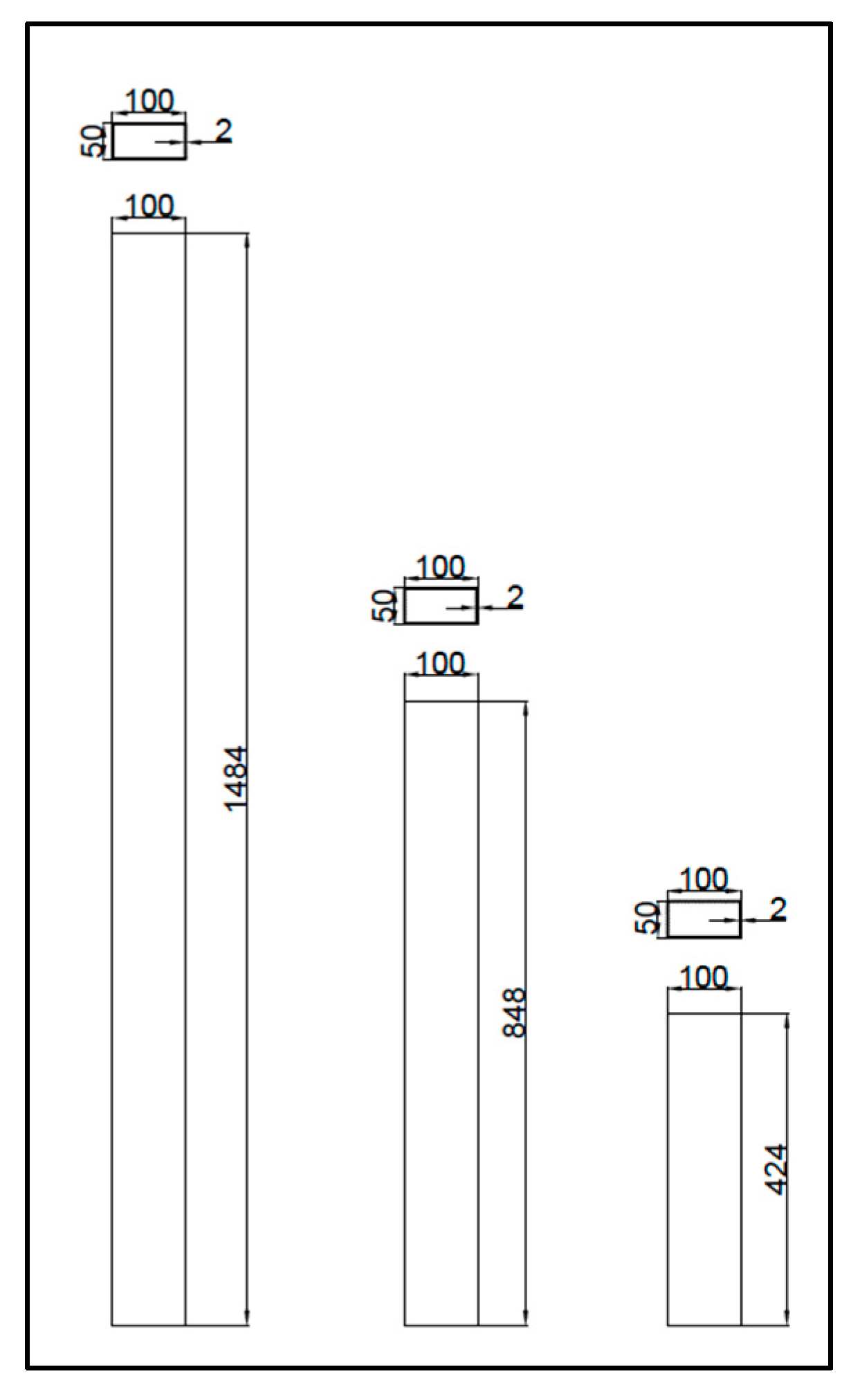
The steel fibres employed in this investigation exhibited a tensile strength of 1800 MPa, a specific gravity of 7.8, a diameter of 0.60 mm, and a span of 50 mm. The glass fibres used had measurements of 6 mm in length, 22 µm in diameter, 273 in aspect ratio, 2.68 in specific gravity, and 1700 MPa in tensile strength. The employed carbon fibres had parameters of 5 mm in length, 10 µm in diameter, an aspect ratio of 500, 1.8 specific gravity, and 4900 MPa in tensile strength. The coir fibres used had properties of 40 mm in length, 0.40 mm in diameter, an aspect ratio of 100, 1.5 specific gravity, and 500 MPa in tensile strength. The jute fibres used had a tensile strength of 600 MPa, a specific gravity of 1.5, a span of 4 mm, a diameter of 20 µm, and an aspect ratio of 200. The sisal fibres used had a diameter of 0.35 mm, a length of 40 mm, a specific gravity of 1.45, an aspect ratio of 114, and a tensile strength of 800 MPa.
The concrete infill used was made of the materials listed below. In accordance with IS 12269-2013, OPC 53 grade cement was considered in this experimental program. The material used in this research work was river sand, which was available locally. According to Indian Standard 2386-1963, 4.75 mm was the maximum size of fine aggregate, satisfying zone II. River sand, with a specific gravity of 2.56, was used. The size of the graded crumbled stone utilized as coarse aggregate was 20 mm and 12.5 mm, as per Indian Standard 2386-1963. The specific gravity of the aggregate made from crushed stone is 2.69. Superplasticizer was used to enhance the workability of the concrete and reduce the amount of water.
The cold-formed hollow steel column used in this experimental study was of size 100 mm width, 50 mm depth and 2 mm thickness, as shown in Figure 1. Three different slenderness ratios were adopted in this study: 70, 40, and 20. With respect to the slenderness ratios, the height of the column varied. The concrete filled steel tubular columns tested in this study is shown in Figure 2.
This experimental study made use of M40 concrete grade. The mix proportions for the M40 grade were taken as follows: 328.33 kg/m3 of cement, 1237.80 kg/m3 of coarse aggregate, 791.28 kg/m3 of fine aggregate, and a water-cement ratio of 0.45.

2.2. Test Specimen

The concentric axial load-carrying capacity of rectangular steel tubular columns filled with concrete was ascertained using an experimental program involving 24 specimens. Cold-formed plain steel columns were used to create the concrete-filled steel tubular columns, which were then filled with a variety of infill materials, including normal concrete, steel FRC, carbon FRC, glass FRC, coir FRC, jute FRC, and sisal FRC. For the experimental study, columns with dimensions of 100 mm × 50 mm were used. To analyze the column’s entire behaviour, 3 distinct slenderness values (λ = 20, 40 and 70) were chosen. The thickness of the cold-formed steel column adopted in this study was 2 mm. The description of specimen details is shown in Table 1.
Artificial fibres such as Steel, carbon, and glass fibres and natural fibres such as coir, jute, and sisal fibres were the several types of fibres employed in the concrete infill. Different volumetric percentages of 0%, 0.5%, 1.0%, 1.5%, and 2.0% fibres were added to individually optimize the fibre-reinforced concrete infill used in the cold-formed steel columns. The optimization of different fibre-reinforced concrete was established using the results of the compression results. The volumetric ratio of 1.5% was chosen for the steel and carbon FRC. The volumetric ratio of the concrete with glass fibre reinforcement was optimized at 1.0%. The optimal volumetric ratio for the coir FRC was 2.0%. The volumetric ratio for the jute and sisal FRC was optimized at 1.5% [43].

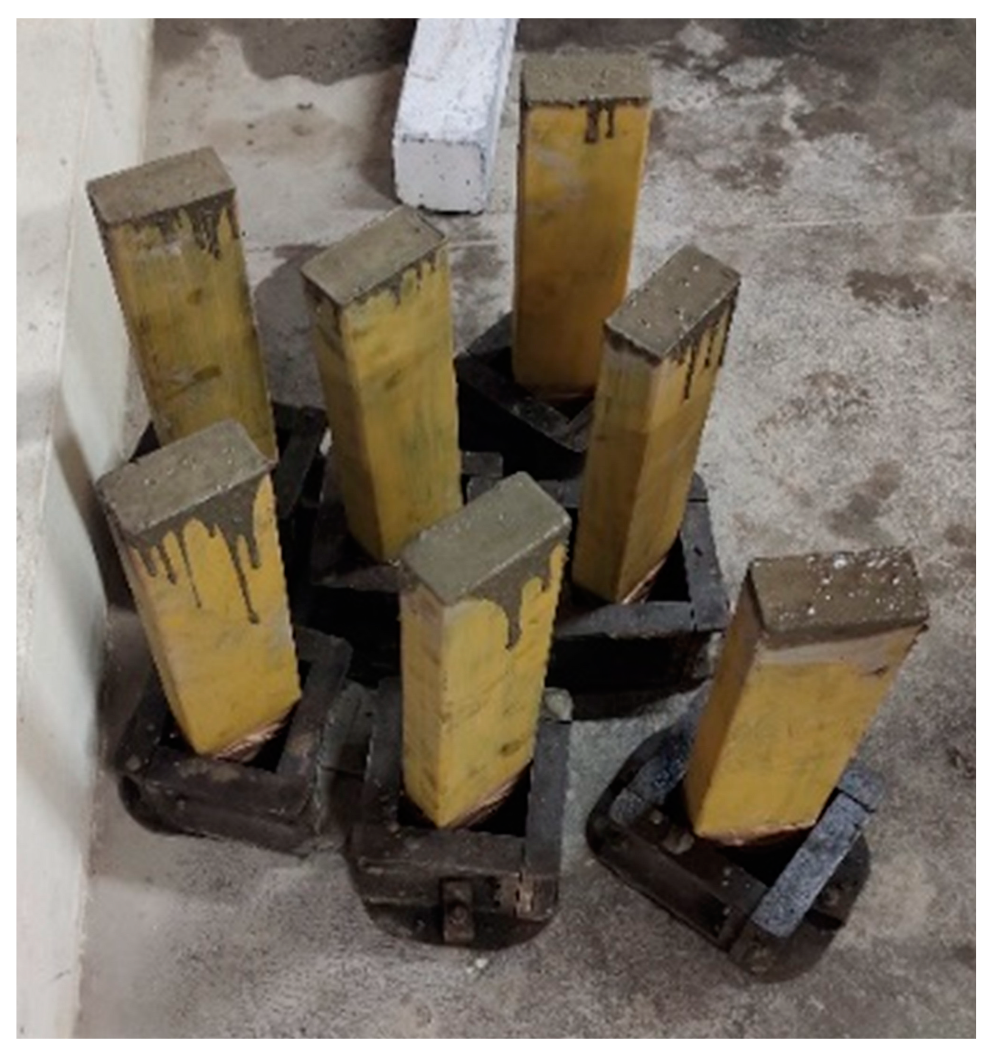
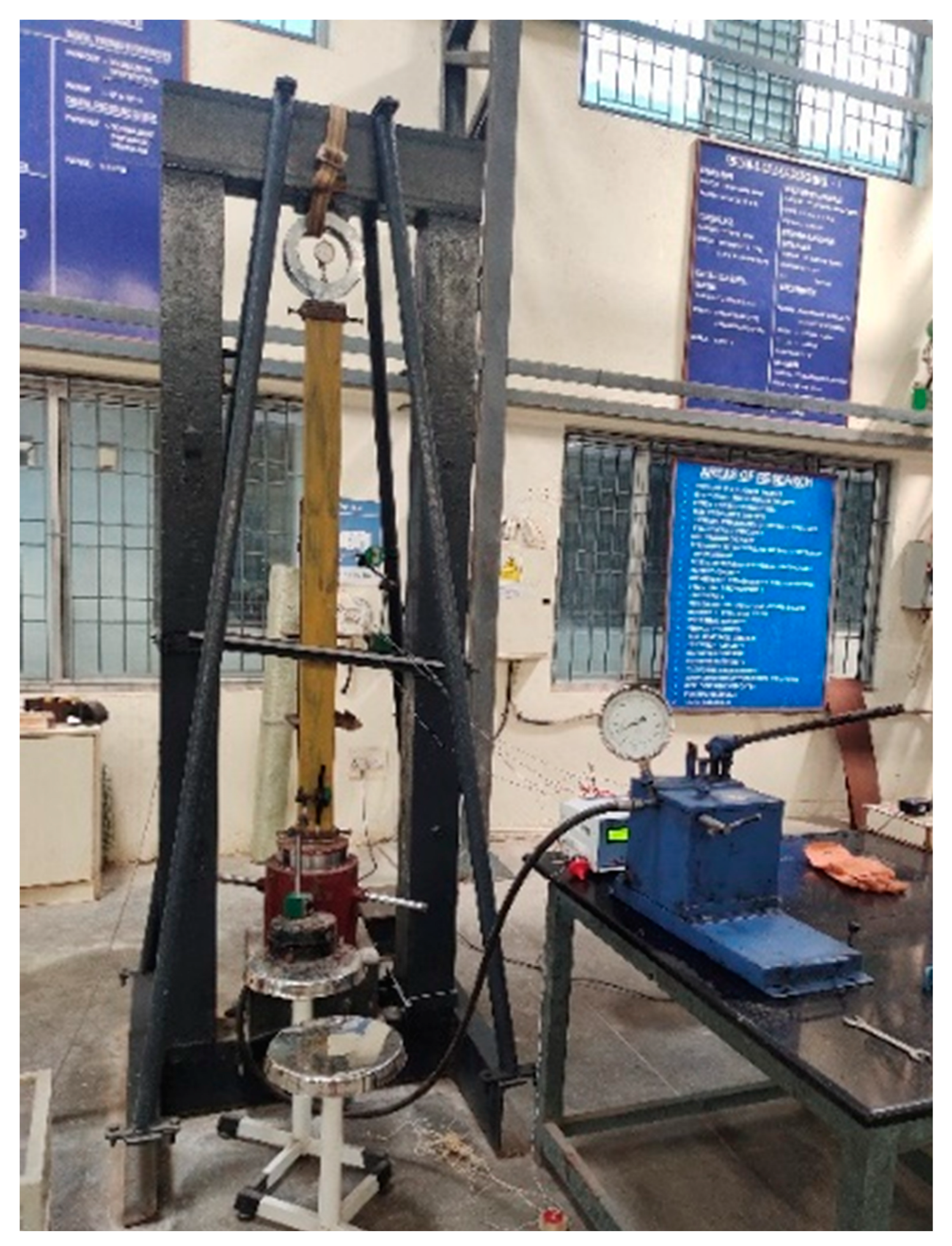
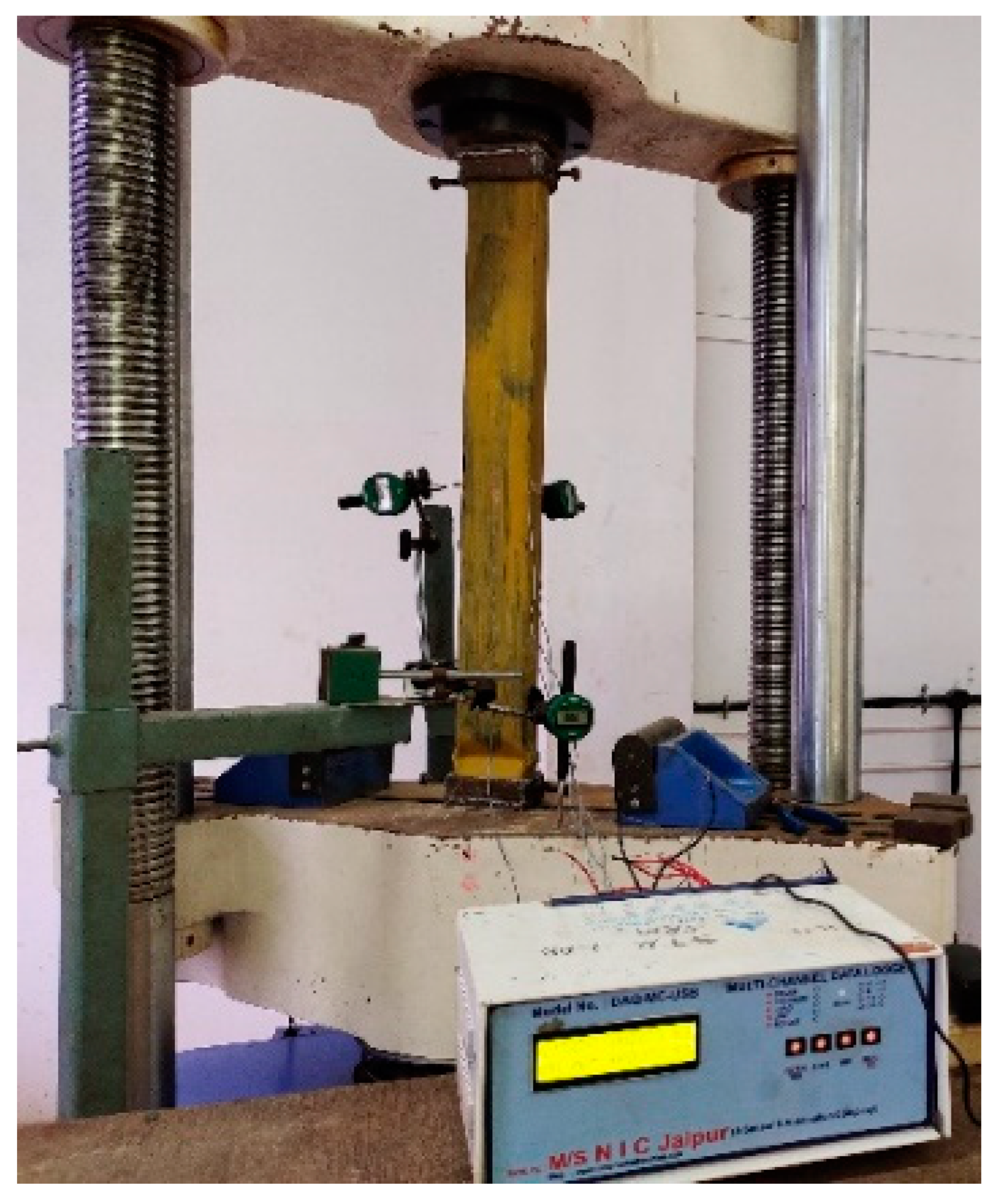
2.3. Specimen Preparation and Experimental Procedure

The requisite lengths of steel tubes were cut and machined to the desired slenderness. The grease was then scraped out of the hollow steel tubes. Anti-corrosive paint was applied to the hollow steel tube’s exterior. To stop the bottom of the steel tube from leaking concrete, it was sealed with a thick mica sheet. The steel tube was then filled with several types of concrete infills before being vibrated. A vibrator was used to compact the three or four layers of concrete. Figure 3 depicts the specimens being cast.
A metal cap was screwed to the top and bottom surfaces of the column after the column was hardened for 28 days. Then, at mid-height on either side, strain gauges were mounted. To gauge the column’s axial shortening, a deflectometer was placed at its base. Two additional deflectometers were placed at mid-height to measure the longitudinal and lateral deflections on either side of the cross-section. The specimen’s axial load was applied using a hydraulic pump. The behaviour of the column specimen was recorded using dial gauges. Figure 4 depicts the setup for the experiment testing on columns. A 5 kN increment was used to apply the load on the column. Until failure, the strain and deflection were recorded for each increase in load.

3. Results

3.1. Failure Modes

Three various lengths of hollow light gauge steel columns underwent axial tests. The findings show that local steel column buckling caused all hollow columns to fail. Hollow steel tubular columns had a relatively lower load-carrying capacity. The axial shortening was found to be greater in hollow columns. The mid-column strain was also observed to be higher in the hollow column sections. Figure 5 depicts the test setup of the hollow steel tubular column. The hollow steel tubular column experienced local buckling at the bottom, with inward buckling at the longer side of the cross-section and outward buckling at the shorter side of the cross-section.

3.1.1. Medium Column

The ultimate load of the stub, short, and medium columns for M40-grade concrete with different forms of infill is shown in Table 2.
In medium columns, the load-carrying capacity of the fibre-reinforced concrete was observed to be higher than conventional concrete. Steel FRC, glass FRC, and sisal FRC exhibited the highest load-carrying capacities when exposed to axial loading. When compared to a regular concrete-filled steel tubular column, the percentage increase in ultimate load for steel, carbon, and glass FRC-infilled steel tubular columns was 23.11%, 21.04%, and 24.74%, respectively. The percentage increase in ultimate load of coir, jute and sisal fibre-reinforced concrete-infilled steel tubular columns was observed as 16.37%, 18.85% and 21.81%, respectively, when compared to conventional concrete-filled steel tubular columns. When compared to a conventional steel tubular column filled with concrete, a hollow medium column’s ultimate load was found to be 58.95% lower.
Steel, glass, and sisal fibres incorporated into the concrete improved the column’s mid-height displacement. The graphical illustration of load vs. deflection for hollow medium columns and medium columns with various types of concrete infills is shown in Figure 6. The mid-height strain of the columns was lower in conventional concrete-infilled columns than in artificial fibre-reinforced concrete-infilled columns. In comparison, the mid-height strain of conventional concrete-infilled columns and natural fibre-reinforced concrete-infilled columns were more or less similar. The graphical representation of load vs. mid-height strain for hollow medium columns and medium columns with various types of concrete infills is shown in Figure 7.
Similarly, when compared to columns with other types of fibre-reinforced concrete infills, the axial shortening of the columns with carbon, coir, and jute infills was observed to be the least. Comparing composite columns filled with steel, carbon, and glass FRC to those filled with conventional concrete, the percentage decrease in axial shortening was found to be 4.44%, 36.39%, and 12.10%, respectively. Comparing coir, jute, and sisal FRC-filled steel tubular columns to conventional CFST columns, the percentage decrease in axial shortening was found to be 40.91%, 37.40%, and 17.92%, respectively. The graphical representation of load vs. axial shortening for medium columns and hollow medium columns with various types of concrete infills is shown in Figure 8. In medium columns, the failure occurred with the overall buckling of the column. The failure of the medium column is represented in Figure 9.
Due to the confining effect of conventional concrete and fibre-reinforced concrete by the steel section as compared to the hollow columns, the strength of the in-filled columns is significantly increased. In comparison to conventional concrete-infilled and hollow columns, the axial shortening of fibre-reinforced concrete-infilled columns is reduced due to the higher characteristic compressive strength of the infill. The failure mode for axially loaded medium columns is overall buckling with a considerable amount of local buckling.

3.1.2. Short Column

The load-bearing capacity of short columns with FRC infill was observed to be higher than conventional concrete-infilled columns. From Table 2, Comparing steel tube columns filled with steel, carbon, and glass fibre-reinforced concrete to those filled with conventional concrete, the percentage rise in maximum load was found to be 21.68%, 13.67%, and 22.82%, respectively. The percentage increase in ultimate load of coir, jute and sisal fibre-reinforced concrete-infilled steel tubular column was observed as 13.61%, 12.60%, and 16.39%, respectively, when compared to the CFST column. When compared to a conventional CFST column, the ultimate load of the short hollow column was found to be reduced by 58.14%. Steel, glass, and sisal fibres incorporated into the concrete improved the column’s mid-height displacement. The FRC infill improved the resistance of the column towards axial load by taking up more deflection before failure. Table 3 displays the stiffness of several CFST columns. Figure 10 provides a graphic representation of the relationship between load and deflection for short hollow columns and short columns with various types of concrete infills. The mid-height strain of conventional concrete-infilled columns was lower than that of artificial and natural fibre-reinforced concrete-infilled columns. This demonstrates the ductile behaviour of steel tube columns filled with FRC. The graphical representation of load vs. mid-height strain for short hollow columns and short columns with various types of concrete infills is shown in Figure 11.
From Table 3, it is derived that the stiffness was maximum for the conventional concrete-filled steel tubular column, which shows the stiff behaviour of the stub column. Similarly, the stiffness of the medium column was observed to be minimum in the carbon FRC-filled steel tubular column, which showed the improved ductile behaviour of the column. For short columns, sisal FRC-filled steel tubular columns demonstrated improved ductile behaviour of the column and exhibited the least amount of stiffness. For stub columns, steel FRC-filled steel tubular columns with improved ductile behaviour were observed to have the minimum stiffness.
The axial shortening of the columns with carbon, coir, and jute FRC infills was also observed to be less than that of columns with other types of fibre-reinforced concrete infills. Contrasting the use of conventional concrete and steel tube columns filled with steel, carbon, and glass fibre-reinforced concrete, the percentage decrease in axial shortening was found to be 4.15, 8.39, and 2.25, respectively. Comparing coir, jute, and sisal FRC-infilled steel tubular columns to conventional CFST columns, the percentage reduction in axial shortening was found to be 15.19%, 12.62%, and 4.98%, respectively. Figure 12 illustrates the relationship between load and axial shortening for hollow short columns and short columns with different kinds of concrete infills. According to Figure 13, localized buckling and crushing of the infilled concrete at the bottom of the column contributed to the column’s failure.

3.1.3. Stub Column

In comparison to conventional concrete-filled columns, stub columns with fibre-reinforced concrete infill performed better in terms of load-carrying capacity. When contrasted to a conventional CFST column, Table 2 shows that the percentage increase in the ultimate loads for steel, carbon, and glass fibre-reinforced concrete-infilled steel tubular columns was observed to be 31.6%, 22.27%, and 33.93%, respectively. The percentage increase in the ultimate loads of coir, jute and sisal fibre-reinforced concrete-infilled steel tubular columns was observed as 23.41%, 27.42%, and 28.08%, respectively, when compared to conventional CFST columns. When compared to conventional concrete-filled steel tubular columns, the ultimate load of hollow stub columns was found to be 53.13% lower. Steel, glass, and sisal fibres incorporated into the concrete improved the columns’ mid-height displacement. The fibre-reinforced concrete infill improved the resistance of the column to axial load by taking up more deflection before failure. The graphical illustration of load vs. deflection for hollow stub columns and stub columns with various types of concrete infills is shown in Figure 14. Compared to artificial and natural fibre-reinforced concrete-infilled columns, the mid-height strain of the columns was lower in conventional concrete-infilled columns. This demonstrates the ductile behaviour of steel tube columns filled with fibre-reinforced concrete. Figure 15 demonstrates load vs. mid-height strain for stub columns that are hollow and for stub columns that have different kinds of concrete infills.
Similarly, the axial shortening of the columns with the implementation of carbon, coir and sisal FRC infills was observed to be less than columns with other types of fibre-reinforced concrete infills. Comparing rectangular steel columns filled with steel, carbon, and glass FRC to those filled with ordinary concrete, the percentage decrease in axial shortening was found to be 4.98%, 13.84%, and 7.40%, respectively. Comparing coir, jute, and sisal FRC-infilled rectangular steel columns to conventional concrete-filled steel tubular columns, the percentage decrease in axial shortening was found to be 20.28%, 8.06%, and 12.67%, respectively. The graphical representation of load vs. axial shortening for hollow stub columns and stub columns with various types of concrete infills is shown in Figure 16. In stub columns, the failure occurred with the crushing of the column at the bottom of the column, except for the carbon and coir FRC-infilled steel tubular columns. In carbon and coir FRC-infilled steel tubular columns, the failure of the column occurred due to crushing at the top of the column. Table 4 displays the ductility index of several concrete-filled steel tubular columns. All of the in-filled short and stub columns were discovered to be crushed by the axial load; shear failures were not seen. Local buckling along the bottom support was the reason for the failure of the hollow short and stub columns.
In the stub columns, the ductility index was found to be maximum in the steel fibre-reinforced concrete-infilled columns and minimum in the hollow steel tubes. In the short columns, the ductility index was found to be minimum in hollow steel tubes and maximum in columns filled with steel fibre-reinforced concrete. The ductility index for medium columns was found to be lowest in hollow steel tubes and highest in steel fibre-reinforced concrete-infilled columns. As compared to hollow steel tubular columns and normal concrete-infilled steel tubular columns, fibre-reinforced concrete-infilled columns exhibit significantly better ductile behaviour.

3.1.4. Theoretical Investigation

The cold-formed steel concrete composite column with various types of fibre-reinforced concrete was adopted for theoretical investigation with four different codes of practices such as EC-4, ACI 318-11, AISC 360-16 and AS5100-6. The theoretical values for the ultimate loads of the composite columns are represented in Table 5.
In medium short and stub columns, the ratio between the ultimate experimental load and the ultimate theoretical load was determined, as mentioned in Table 6.

4. Conclusions

Three main types of steel-concrete composite columns with various slenderness ratios were examined in this work. These three main groups included conventional and other types of FRC-filled steel tube columns that were tested in axial compression. The following conclusion is reached in view of the study’s findings,
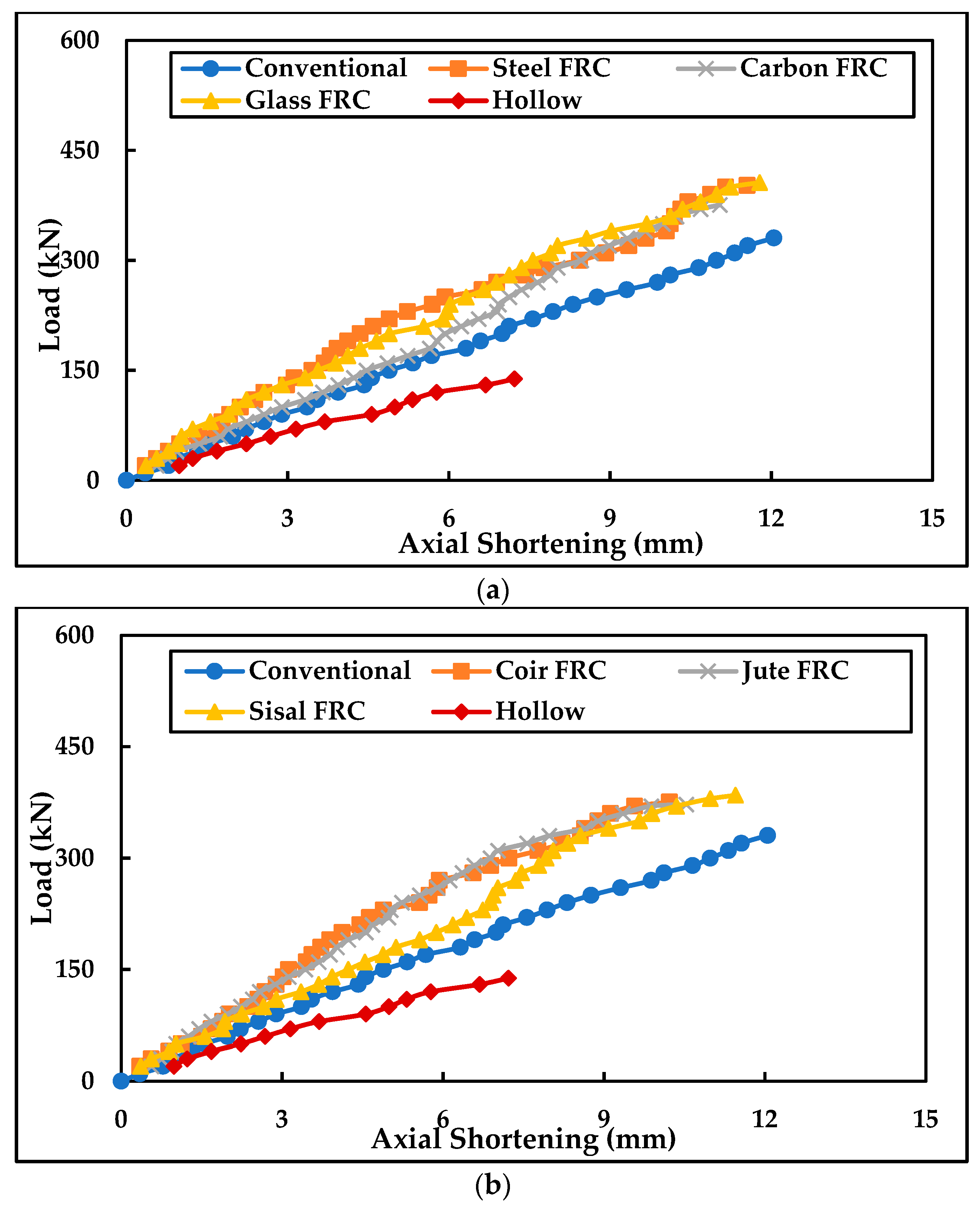
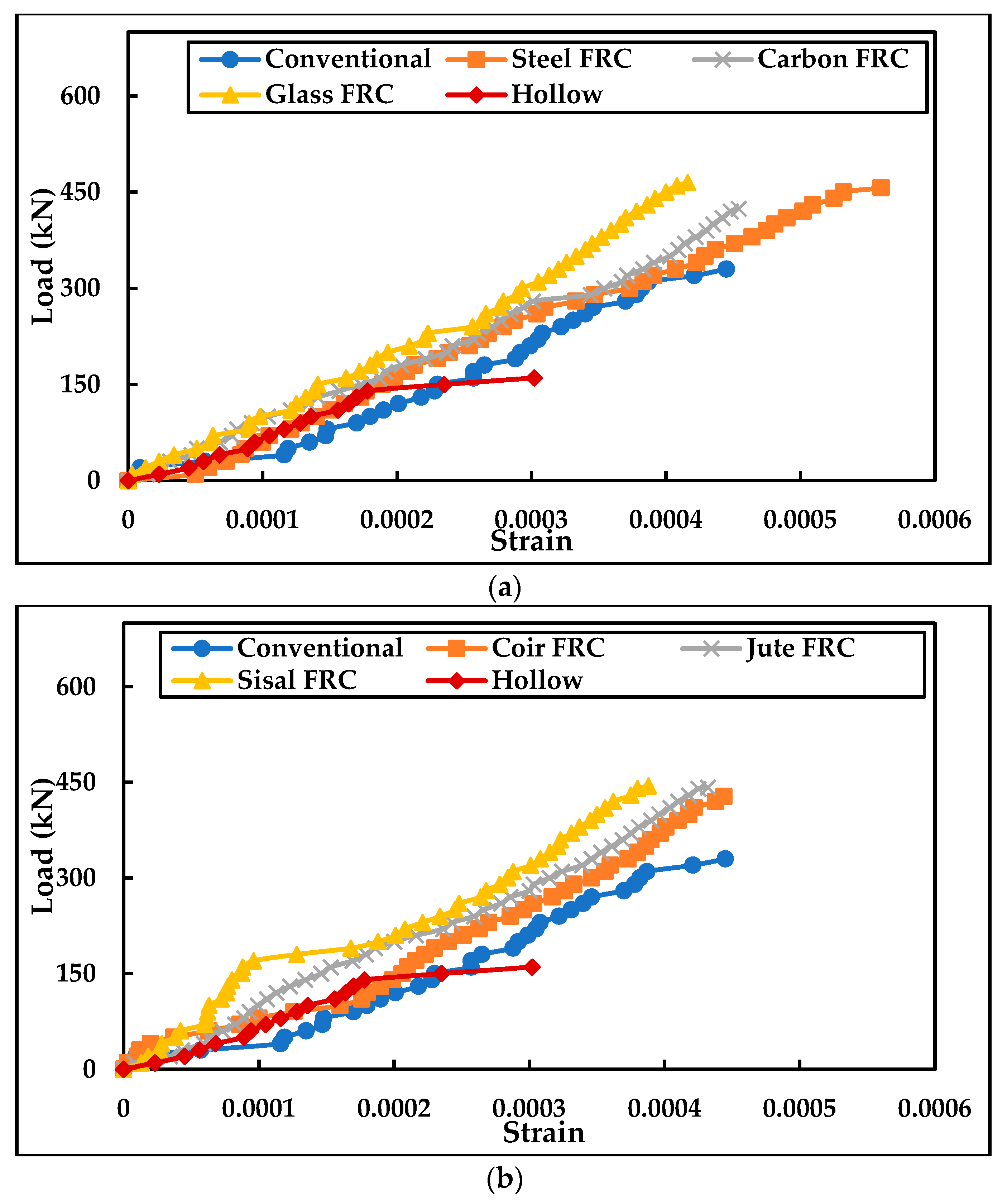
  • With the use of glass, steel, and sisal fibre-reinforced concrete infill, the maximum ultimate load of a steel tubular column filled with FRC was observed;
  • When compared to hollow steel tubular columns, the ultimate load of FRC-infilled rectangular steel columns was enhanced up to three times. Hence, fibre-reinforced concrete-infilled steel tubular columns can be effectively used in structures with high loads;
  • In the stub, short, and medium columns, the load-carrying capacity of the glass fibre-reinforced concrete-infilled steel tubular column was observed to be higher than the other types of fibre-reinforced concrete-infilled steel tubular columns. The percentage increase was observed as 203.88%, 193.48%, and 190.03% when compared to hollow cold-formed steel tubular columns in medium, short, and stub columns, respectively;
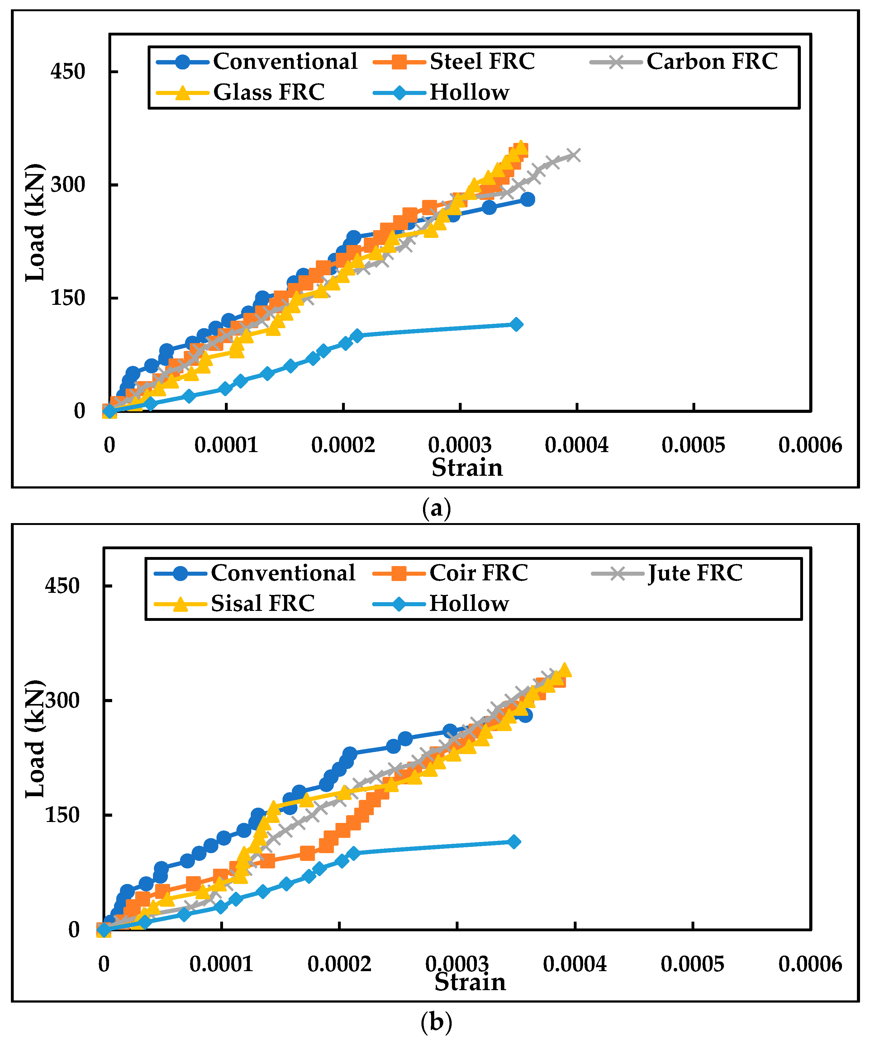
  • The load-strain plots showed that the steel fibre-reinforced concrete-infilled columns performed well in terms of ductility during the testing of the stub, short, and medium columns;
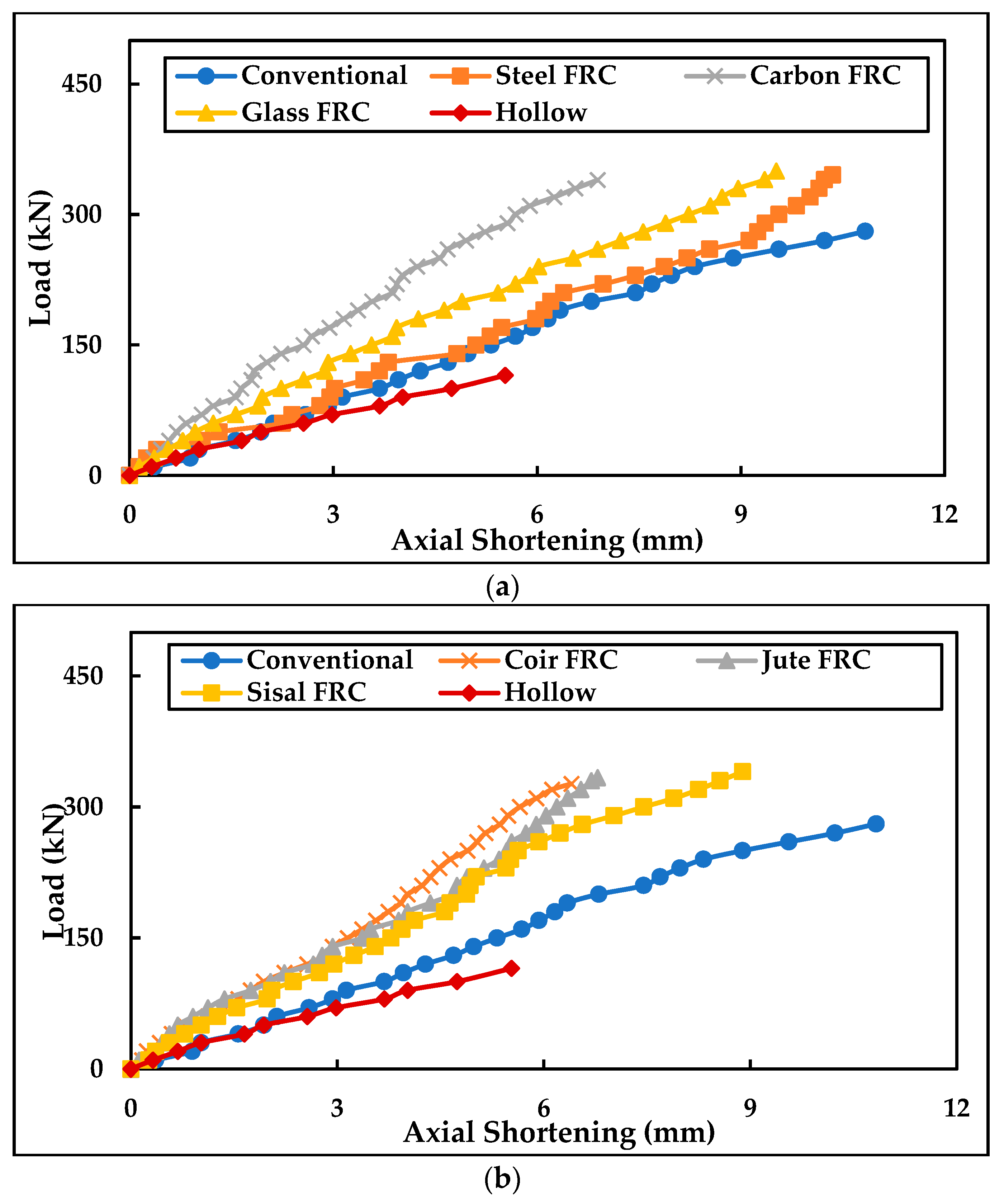
  • It was discovered that the in-filled medium columns made of glass fibre-reinforced concrete experienced 12.10% less axial shortening than the other in-filled medium columns. When compared to other in-filled short columns, steel fibre-reinforced concrete’s axial shortening was determined to be 11.50% less. It was discovered that the axial shortening of the steel fibre-reinforced concrete in-filled stub columns was 11.50% less than that of the other in-filled stub columns;
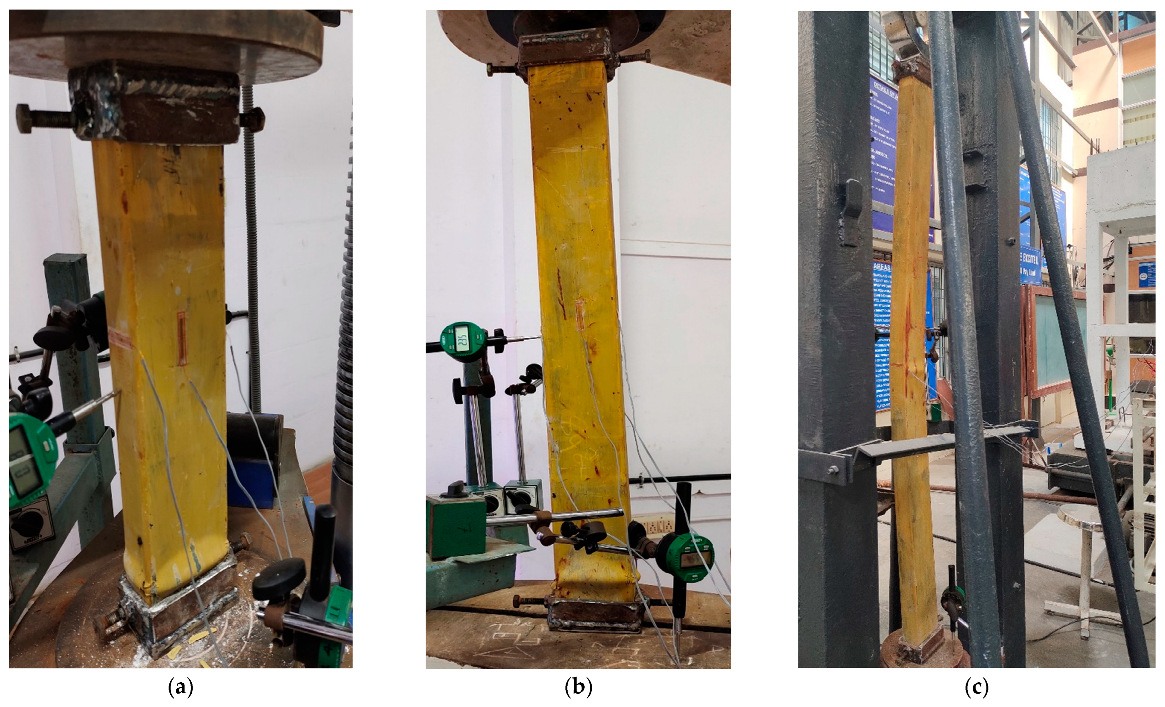
  • CFST columns with a low slenderness ratio (λ = 20 and 40) failed due to local buckling and crushing of the concrete infill. Contrarily, concrete-filled steel tubular columns with greater slenderness ratios (λ = 70) demonstrated column failure through overall buckling of the composite column;
  • Due to the crushing of in-fills on the approach of failure, the bottom of each column that was in-filled with concrete buckled externally;
  • The single curvature buckling failure pattern was the one that was seen in the axially loaded medium column;
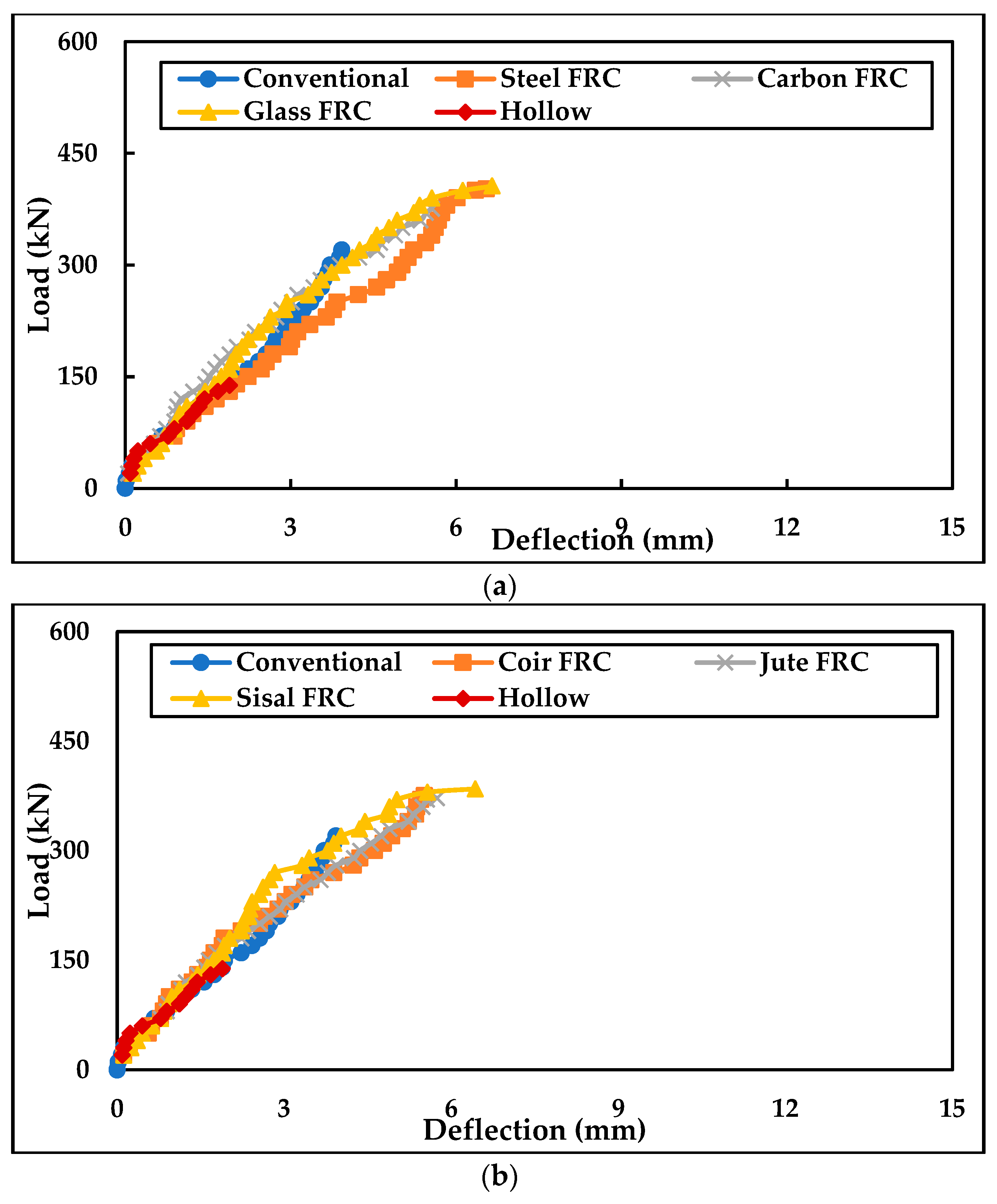
  • Fibre-reinforced concrete-infilled steel tubular columns had the ability to take more deformations and strain before failure than conventional concrete-filled steel tubular columns and hollow tubular columns, which shows improved ductile behaviour;
  • Glass, steel, and sisal fibre-reinforced concrete improved the overall behaviour of the column and hence can be effectively used in cold-formed steel tubular columns as infill in structural applications;
  • The performance of natural fibres infilled concrete was low due to the non-uniform dispersion of fibres within the column due to its fibre characteristics;
  • Due to its poor ductile behaviour, the axial shortening of the column was noted to be at its lowest with the use of carbon, coir, jute, and sisal fibre-reinforced concrete infill;
  • Further studies can be conducted by providing additional dispersion agents for the fibre-reinforced concrete infill, and different types of fibres can be incorporated into the infill. Similar studies can be carried out, varying the loading conditions.

Author Contributions

F.M.D.S.M.: Conducted the experiments. S.S.S.: supervised the research as well as the validation of results. F.M.D.S.M. and S.S.S.: introduced the idea of fibre-reinforced concrete in this project, wrote, reviewed, submitted the paper, collaborated in and coordinated the research. F.M.D.S.M. and S.S.S.: suggested and chose the journal for submission. F.M.D.S.M. and S.S.S.: paper review and editing of the final draft. All authors have read and agreed to the published version of the manuscript.

Funding

This research received no external funding.

Data Availability Statement

The data presented in this study are available on request from the corresponding author.

Conflicts of Interest

This manuscript has not been submitted to, nor is it under review by, another journal or other publishing venue. The authors have no affiliation with any organization with a direct or indirect financial interest in the subject matter discussed in the manuscript.

References

  1. Shanmugam, N.; Lakshmi, B. State of the art report on steel–Concrete composite columns. J. Constr. Steel Res. 2001, 57, 1041–1080. [Google Scholar] [CrossRef]
  2. Han, L.-H.; Li, W.; Bjorhovde, R. Developments and advanced applications of concrete-filled steel tubular (CFST) structures: Members. J. Constr. Steel Res. 2014, 100, 211–228. [Google Scholar] [CrossRef]
  3. Zhao, X.-L.; Han, L.-H.; Lu, H. Concrete-Filled Tubular Member, 1st ed.; Spon Press: Oxford, UK, 2010. [Google Scholar]
  4. Rahnavard, R.; Craveiro, H.D.; Lopes, M.; Simões, R.A.; Laím, L.; Rebelo, C. Concrete-filled cold-formed steel (CF-CFS) built-up columns under compression: Test and design. Thin-Walled Struct. 2022, 179, 109603. [Google Scholar] [CrossRef]
  5. Evirgen, B.; Tuncan, A.; Taskin, K. Structural behavior of concrete filled steel tubular sections (CFT/CFSt) under axial compression. Thin-Walled Struct. 2014, 80, 46–56. [Google Scholar] [CrossRef]
  6. Uy, B. Strength of concrete filled steel box columns incorporating local buckling. J. Struct. Eng. 2000, 126, 341–352. [Google Scholar] [CrossRef]
  7. Ren, Q.X.; Han, L.H.; Lam, D.; Hou, C. Experiments on special-shaped CFST stub columns under axial compression. J. Constr. Steel Res. 2014, 98, 123–133. [Google Scholar] [CrossRef]
  8. He, Z.; Zhou, X. Strength design curves and an effective width formula for coldformed steel columns with distortional buckling. Thin-Walled Struct. 2014, 79, 62–70. [Google Scholar] [CrossRef]
  9. Ge, H.B.; Usami, T. Strength analysis of concrete-filled thin-walled steel box columns. J. Constr. Steel Res. 1994, 30, 259–281. [Google Scholar] [CrossRef]
  10. Huang, C.S.; Yeh, Y.K.; Liu, G.Y.; Hu, H.T.; Tsai, K.C.; Weng, Y.T.; Wang, S.H.; Wu, M.H. Axial load behaviour of stiffened concrete filled steel columns. J. Struct. Eng. 2002, 28, 593–598. [Google Scholar] [CrossRef] [Green Version]
  11. Tao, Z.; Han, L.-H.; Wang, Z.-B. Experimental behaviour of stiffened concrete-filled thin-walled hollow steel structural (HSS) stub columns. J. Constr. Steel Res. 2005, 61, 962–983. [Google Scholar] [CrossRef]
  12. Nassirnia, M.; Heidarpour, A.; Zhao, X.L.; Minkkinen, J. Innovative hollow corrugated columns: A fundamental study. Eng. Struct. 2015, 94, 43–53. [Google Scholar] [CrossRef]
  13. Tao, Z.; Han, L.H.; Wang, D.Y. Strength and ductility of stiffened thin-walled hollow steel structural stub columns filled with concrete. Thin-Walled Struct. 2008, 46, 1113–1128. [Google Scholar] [CrossRef]
  14. Shen, J.; Wadee, M.A. Length effects on interactive buckling in thin-walled rectangular hollow section struts. Thin-Walled Struct. 2018, 128, 152–170. [Google Scholar] [CrossRef]
  15. Thai, H.-T.; Uy, B.; Khan, M.; Tao, Z.; Mashiri, F. Numerical modelling of concrete-filled steel box columns incorporating high strength materials. J. Constr. Steel Res. 2014, 102, 256–265. [Google Scholar] [CrossRef]
  16. Ellobody, E.; Young, B. Structural performance of cold-formed high strength stainless steel columns. J. Constr. Steel Res. 2005, 61, 1631–1649. [Google Scholar] [CrossRef]
  17. Senthilkumar, R.; Divya, M.; Roy, S.D. Behaviour of cold-formed steel-concrete composite columns under axial compression: Experimental and numerical study. Structures 2022, 44, 487–502. [Google Scholar]
  18. Zhang, S.; Li, X.; Li, J.; Lu, W.; Chen, J. Behavior comparison of seven-types of steel–Concrete composite stub columns under axial compression. Eng. Struct. 2022, 252, 113637. [Google Scholar] [CrossRef]
  19. Fam, A.; Qie, F.S.; Rizkalla, S. Concrete-filled steel tubes subjected to axial compression and lateral cyclic loads. Eng. Struct. 2004, 130, 631–640. [Google Scholar] [CrossRef] [Green Version]
  20. Giakoumelis, G.; Lam, D. Axial capacity of circular concrete-filled tube columns. J. Constr. Steel Res. 2004, 60, 1049–1068. [Google Scholar] [CrossRef]
  21. Yu, Z.-W.; Ding, F.-X.; Cai, C. Experimental behavior of circular concrete-filled steel tube stub columns. J. Constr. Steel Res. 2007, 63, 165–174. [Google Scholar] [CrossRef]
  22. Ricles, J.M.; Paboojian, S.D. Seismic performance of steel-encased composite columns. J. Struct. Eng. 1994, 120, 2474–2494. [Google Scholar] [CrossRef]
  23. Mirza, S.A.; Hyttinen, V.; Hyttinen, E. Physical tests and analyses of composite steel-concrete beam-columns. J. Struct. Eng. 1996, 122, 1317–1326. [Google Scholar] [CrossRef]
  24. Lai, B.; Liew, J.R.; Wang, T. Buckling behaviour of high strength concrete encased steel composite columns. J. Constr. Steel Res. 2019, 154, 27–42. [Google Scholar] [CrossRef]
  25. Aboutaha, R.S.; Machado, R.I. Seismic resistance of steel-tubed high-strength reinforced-concrete columns. J. Struct. Eng. 1999, 125, 485–494. [Google Scholar] [CrossRef]
  26. Brown, N.K.; Kowalsky, M.J.; Nau, J.M. Impact of D/t on seismic behavior of reinforced concrete filled steel tubes. J. Constr. Steel Res. 2015, 107, 111–123. [Google Scholar] [CrossRef]
  27. Xiamuxi, A.; Liu, X.R.; Hasegawa, A. Study of the concrete in reinforced concrete-filled steel tube column under axial loading. J. Constr. Steel Res. 2020, 170, 106111. [Google Scholar] [CrossRef]
  28. Wang, Q.X.; Zhao, D.Z.; Guan, P. Experimental study on the strength and ductility of steel tubular columns filled with steel-reinforced concrete. Eng. Struct. 2004, 26, 907–915. [Google Scholar] [CrossRef]
  29. Cai, J.M.; Pan, J.L.; Wu, Y.F. Mechanical behavior of steel-reinforced concrete-filled steel tubular (SRCFST) columns under uniaxial compressive loading. Thin-Wall Struct. 2015, 97, 1–10. [Google Scholar] [CrossRef]
  30. Farajpourbonab, E.; Kute, S.Y.; Inamdar, V.M. Steel-reinforced concrete-filled steel tubular columns under axial and lateral cyclic loading. Int. J. Adv. Struct. Eng. 2018, 10, 61–72. [Google Scholar] [CrossRef] [Green Version]
  31. Hassanein, M.; Kharoob, O.; Liang, Q. Circular concrete-filled double skin tubular short columns with external stainless steel tubes under axial compression. Thin-Walled Struct. 2013, 73, 252–263. [Google Scholar] [CrossRef]
  32. Li, Y.-J.; Han, L.-H.; Xu, W.; Tao, Z. Circular concrete-encased concrete-filled steel tube (CFST) stub columns subjected to axial compression. Mag. Concr. Res. 2016, 68, 995–1010. [Google Scholar] [CrossRef]
  33. Ayough, P.; Sulong, N.H.R.; Ibrahim, Z. Analysis and review of concrete-filled double skin steel tubes under compression. Thin-Walled Struct. 2020, 148, 106495. [Google Scholar] [CrossRef]
  34. Xiong, M.X.; Xiong, D.X.; Liew, J.Y.R. Axial performance of short concrete filled steel tubes with high-and ultra-high-strength materials. Eng. Struct. 2017, 136, 494–510. [Google Scholar] [CrossRef]
  35. Liang, Q.Q.; Fragomeni, S. Nonlinear analysis of circular concrete-filled steel tubular short columns under axial loading. J. Constr. Steel Res. 2009, 65, 2186–2196. [Google Scholar] [CrossRef]
  36. Li, W.; Chen, B.; Han, L.-H.; Lam, D. Experimental study on the performance of steel-concrete interfaces in circular concrete-filled double skin steel tube. Thin-Walled Struct. 2020, 149, 106660. [Google Scholar] [CrossRef]
  37. Lahlou, K.; Lachemi, M.; Aïtcin, P.-C. Confined high-strength concrete under dynamic compressive loading. J. Struct. Eng. 1999, 125, 1100–1108. [Google Scholar] [CrossRef]
  38. Liu, J.; Zhang, S.; Zhang, X.; Guo, L. Behavior and strength of circular tube confined reinforced-concrete (CTRC) columns. J. Constr. Steel Res. 2009, 65, 1447–1458. [Google Scholar] [CrossRef]
  39. Wang, X.D.; Liu, J.P.; Zhang, S.M. Behavior of short circular tubed-reinforced-concrete columns subjected to eccentric compression. Eng. Struct. 2015, 105, 77–86. [Google Scholar] [CrossRef]
  40. Cao, X.-Y.; Shen, D.; Feng, D.-C.; Wang, C.-L.; Qu, Z.; Wu, G. Seismic retrofitting of existing frame buildings through externally attached sub-structures: State of the art review and future perspectives. J. Build. Eng. 2022, 57, 104904. [Google Scholar] [CrossRef]
  41. Sulaiman, A.; Hunaiti, Y.; Abdel-Jaber, M.; Abdel-Jaber, M. Compressive behavior of light–gauge steel tubes filled with concrete containing recycled aggregates. Int. Rev. Appl. Sci. Eng. 2022, 13, 185–196. [Google Scholar] [CrossRef]
  42. Ibrahim, A.Z.; Hunaiti, Y.; El-Nimri, R. Behavior of light-gauge steel short columns filled with normal and lightweight aggregate concrete under concentric axial loading. J. Appl. Eng. Sci. 2022, 20, 1040–1052. [Google Scholar]
  43. More, F.M.D.S.; Subramanian, S.S. Impact of fibres on the mechanical and durable behaviour of fibre-reinforced concrete. Buildings 2022, 12, 1436. [Google Scholar] [CrossRef]
Figure 1. Specifications of the column with dimensions.
Buildings 13 00151 g001
Figure 2. Rectangular steel tubular sections.
Buildings 13 00151 g002
Figure 3. Freshly cast CFST.
Buildings 13 00151 g003
Figure 4. Experimental setup of testing on columns.
Buildings 13 00151 g004
Figure 5. Test setup of hollow steel tubular column.
Buildings 13 00151 g005
Figure 6. Graphical illustration of load vs. deflection of medium column. (a) Artificial FRC. (b) Natural FRC.
Buildings 13 00151 g006
Figure 7. Graphical illustration of load vs. strain of medium column. (a) Artificial FRC. (b) Natural FRC.
Buildings 13 00151 g007
Figure 8. Graphical illustration of load vs. axial shortening of medium column. (a) Artificial FRC. (b) Natural FRC.
Buildings 13 00151 g008
Figure 9. Failure modes in columns. (a) Stub column. (b) Short column. (c) Medium column.
Buildings 13 00151 g009
Figure 10. Graphical illustration of load vs. deflection of short column. (a) Artificial FRC. (b) Natural FRC.
Buildings 13 00151 g010
Figure 11. Graphical illustration of load vs. strain of short column. (a) Artificial FRC. (b) Natural FRC.
Buildings 13 00151 g011
Figure 12. Graphical illustration of load vs. axial shortening of short column. (a) Artificial FRC. (b) Natural FRC.
Buildings 13 00151 g012
Figure 13. Failure in short columns.
Buildings 13 00151 g013
Figure 14. Graphical illustration of load vs. deflection of stub column. (a) Artificial FRC. (b) Natural FRC.
Buildings 13 00151 g014
Figure 15. Graphical illustration of load vs. strain of stub column. (a) Artificial FRC. (b) Natural FRC.
Buildings 13 00151 g015
Figure 16. Graphical illustration of load vs. axial shortening of stub column. (a) Artificial FRC. (b) Natural FRC.
Buildings 13 00151 g016
Table 1. Specimen details of cold-formed steel tubular columns.
Cross-Sectional Dimensions of the Hollow ColumnThickness of the Steel TubeLengthConcrete Infill
100 mm × 50 mm2 mm424 mmNo infill-Hollow
Conventional concrete
Steel fibre-reinforced concrete
Carbon fibre-reinforced concrete
Glass fibre-reinforced concrete
Coir fibre-reinforced concrete
Jute fibre-reinforced concrete
Sisal fibre-reinforced concrete
848 mmNo infill-Hollow
Conventional concrete
Steel fibre-reinforced concrete
Carbon fibre-reinforced concrete
Glass fibre-reinforced concrete
Coir fibre-reinforced concrete
Jute fibre-reinforced concrete
Sisal fibre-reinforced concrete
1484 mmNo infill-Hollow
Conventional concrete
Steel fibre-reinforced concrete
Carbon fibre-reinforced concrete
Glass fibre-reinforced concrete
Coir fibre-reinforced concrete
Jute fibre-reinforced concrete
Sisal fibre-reinforced concrete
Table 2. Ultimate load of various CFST columns.
Type of InfillType of Column
Medium ColumnShort ColumnStub Column
Hollow 115.21 kN138 kN160.22 kN
Conventional concrete280.6 kN330.5 kN366.50 kN
Steel FRC345.44 kN402.12 kN456.62 kN
Carbon FRC339.62 kN375.65 kN424.22 kN
Glass FRC350.10 kN405.92 kN464.68 kN
Coir FRC326.52 kN375.45 kN428.18 kN
Jute FRC333.48 kN372.15 kN442.12 kN
Sisal FRC340.42 kN384.66 kN444.40 kN
Table 3. Stiffness for various concrete-filled steel tubular columns.
Type of InfillStiffness (kN/mm)
Medium ColumnShort ColumnStub Column
Hollow 70.2573.2172.83
Conventional concrete77.5280.2279.16
Steel FRC58.2661.4059.69
Carbon FRC57.6767.5764.77
Glass FRC61.4161.0562.29
Coir FRC59.0568.0264.20
Jute FRC61.5364.8466.39
Sisal FRC61.9059.8362.42
Table 4. Ductility index for various CFST columns.
Type of InfillDuctility Index
Medium ColumnShort ColumnStub Column
Hollow0.610.620.62
Conventional concrete0.690.740.72
Steel FRC0.920.900.90
Carbon FRC0.860.880.87
Glass FRC0.890.900.88
Coir FRC0.880.850.84
Jute FRC0.870.840.83
Sisal FRC0.910.870.87
Table 5. Theoretical ultimate load for various CFST columns.
Type of InfillUltimate Load (kN)
EC 4ACI 318-11AISC 360-16AS 5100-6
Hollow 157.68157.68157.68141.92
Conventional concrete335.21308.58308.58248.43
Steel FRC359.90329.22329.22263.00
Carbon FRC340.95313.46313.46251.88
Glass FRC359.50329.22329.22263.00
Coir FRC363.47332.6332.6265.39
Jute FRC359.50329.22329.22263.00
Sisal FRC360.38329.98329.98263.53
Table 6. Ratio of ultimate experimental load to ultimate theoretical load for various CFST columns.
Codal ProvisionTypes of
Columns
Experimental Ultimate Load/Theoretical Ultimate Load
HollowConventional ConcreteSteel FRCCarbon FRCGlass FRCCoir FRCJute FRCSisal FRC
EC 4Medium column0.740.840.9610.980.90.930.95
Short column0.880.991.121.111.131.041.041.07
Stub column1.021.11.271.251.31.181.231.24
ACI 318-11Medium column0.740.911.051.091.070.991.021.04
Short column1.021.191.391.361.421.291.351.35
Stub column1.021.191.391.361.421.291.351.35
AISC 360-16Medium column0.740.911.051.091.070.991.021.04
Short column0.981.341.531.51.551.421.421.46
Stub column1.131.481.741.691.771.621.691.69
AS 5100-6Medium column0.821.131.321.351.341.241.271.3
Short column0.981.341.531.51.551.421.421.46
Stub column1.131.481.741.691.771.621.691.69
Disclaimer/Publisher’s Note: The statements, opinions and data contained in all publications are solely those of the individual author(s) and contributor(s) and not of MDPI and/or the editor(s). MDPI and/or the editor(s) disclaim responsibility for any injury to people or property resulting from any ideas, methods, instructions or products referred to in the content.

