1. Introduction
In stark contrast to the low productivity of the construction sector relative to other sectors, the strong demand for new constructions is one of the major challenges that all civil engineering departments, firms and engineers have to face. Furthermore, the increasing scarcity of natural resources, low level of automation in design and construction, and lack of labor force are putting the sector in an unsustainable predicament [
1,
2,
3,
4].
Under such circumstances, the industry must undergo fundamental changes. One solution is to espouse the importance of the adoption of prefabrication in construction so as to achieve sustainable development. The advantages of prefabrications have long been recognized [
5,
6,
7,
8,
9,
10]: high cost-efficiency, powerful mass production, and replaceability in case of severe damage. Since prefabricated structures are produced under factory-controlled conditions, they benefit from better and standardized material quality, precise geometry, and lower cost compared to cast-in-place structures. Additionally, precasting reduces weather-related holdups and is cleaner because it eliminates the need for on-site casting and curing. The use of prefabricated elements also reduces health and safety risks by reducing on-site workmanship. Moreover, shrinkage and creep of prefabricated components occur mainly during factory production. In general, by reducing waste emissions, prefabricated buildings offer greater energy efficiency and sustainability compared to traditional monolithic systems.
Of a precast structural system, the beam-to-column connections are the most vulnerable part, susceptible to extensive damage under seismic events [
11]. For this reason, considerable research studies have been conducted to better understand the complex behavior of these connections in precast concrete structures [
12]. In recent years, the precast industry has also attempted to develop imaginative new connections that would perform well during an earthquake [
13].
For example, French et al. [
14] have conducted extensive cyclic tests on various precast connections. They found that, although the plastic hinge was forced to develop within the connection region, the specimens still exhibited ductility and energy dissipation characteristics similar to those of ordinary monolithically cast elements. Through experimentation, Soubra et al. [
15] highlighted the superiority of using fiber-reinforced concrete in critical regions of precast frames; they demonstrated that the alternative measure can dramatically improve the specimens’ cyclic behavior—displacement ductilities even up to 6.0 were achieved. Choi et al. [
16] developed a new wet precast connection which uses steel plates to realize joint continuity and consequently obtains improved seismic performance. Lago et al. [
17] demonstrated the viability of an innovative dry-assembled precast structural system with special mechanical connection devices. Senturk et al. [
18] developed a novel monolithic-like precast connection using bolted plates. The new connection system is easy to assemble and exhibits considerably higher (up to 34%) ductility and ultimate deformability compared with the monolithic connections. Correal et al. [
19] found that the precast connections in one-story industrial facilities designed as per modern ACI codes have good seismic resistance and can resist a lateral drift ratio of at least 3.5%. Recently, some innovative hybrid precast connections have also been developed and their adequate seismic performance has been well illustrated [
20,
21,
22,
23,
24].
According to [
25], the degree of automation in precast constructions is more advanced than any other part of the construction sector. Indeed, the integration of automation and robotics into precast constructions holds promise for sustainable performance in terms of increased construction efficiency, waste reduction, improved workplace safety and enhanced intelligent living environments [
26].
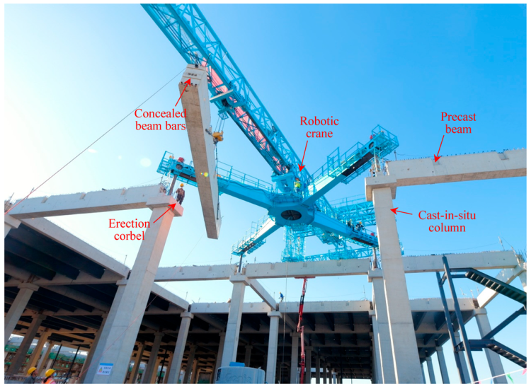
Against this background, an accelerated construction method using robotic cranes developed for industrial facilities, such as warehouse structures, is emerging in China. As shown in
Figure 1, the structure demonstrated is “semi-precast” in that the columns are cast in situ while the beams are prefabricated in plant. Most notably, the lifting of the precast beams can be greatly accelerated with the help of a robotic crane shown in the figure. The robotic crane can move as needed over the cast-in-place columns. It is temporarily fixed to the top of four erected columns during operation. After being lifted the precast beams are placed on the erection corbels (
Figure 1).
This construction method substantially increases the hoisting speed, which is especially suitable for large industrial buildings. However, it requires that the longitudinal steel bars of the precast beams do not extend out of the beam ends, so as to facilitate the temporary connection between the crane’s crawling feet and the top surface of the erected columns.
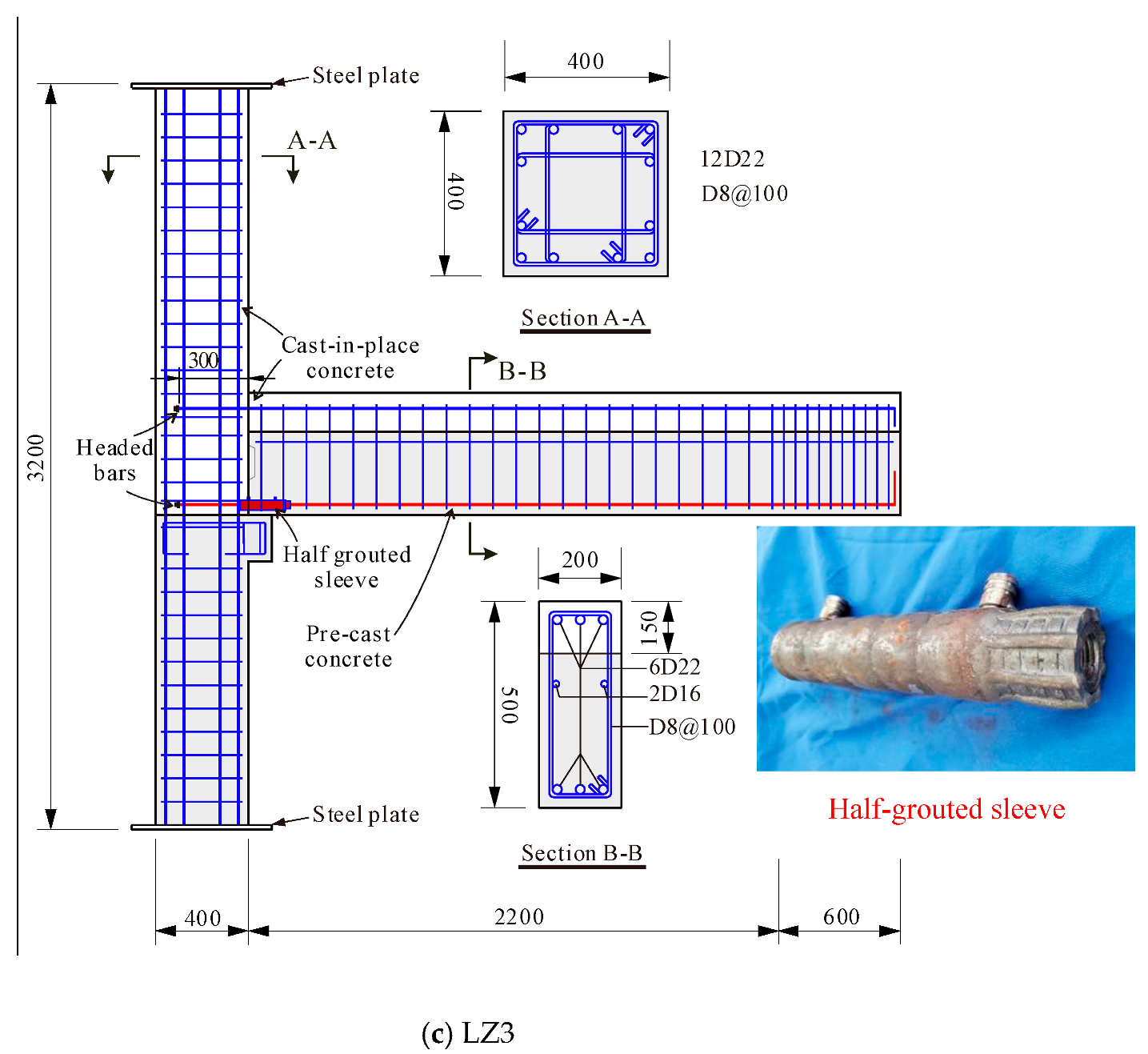
After the crane has walked away, headed reinforcement is used within the joint core to anchor the bottom rebars of the precast beams as well as their top rebars in place, as illustrated in
Figure 2a. Then the joint, the upper column, and the remaining part of the beams are cast at the job site, as shown in
Figure 2b.
For the beam bottom bars, they can be connected to the headed reinforcement by different splicing methods. Despite different types of proposed new precast connection [
16,
17,
18,
19,
20,
21,
22,
23,
24], the most practical methods are to use mechanical couplers or grouted sleeves. However, which connection approach is better is a question. Mechanical couplers are commonly used to connect reinforcing bars, but it is not clear whether they can work in areas densely reinforced with rebars (such as within beam–column joints). Grouted sleeves are the primary forms of rebar connection in precast structures, yet there are often concerns about their construction quality.
To seek out the most suitable way of connecting the headed reinforcement with the beam bottom bars, three large-scale exterior beam–column connections were fabricated and tested under cyclic loading. Two specimens using different bar splicing methods (i.e., mechanical couplers or grouted sleeves) were compared with the control cast-in-place specimen. Test results enabled thorough examination of the seismic performance of the exterior connections in terms of stiffness, strength, and energy dissipation. The potential defects of the mechanical splicing method were pointed out, thus providing design insights and ensuring safety of the semi-precast constructions.
3. Test Results
3.1. General Observations
As expected, all three specimens developed beam hinging failure and behaved in a ductile manner, with the exception of LZ2 when it was subjected to beam upward loading (a positive beam moment was generated under this condition and then the beam bottom bars and the connectors were in tension).
Figure 5 shows the progression of cracks observed in each specimen at different drift ratios, where the drift ratio was defined as the deflection at the beam loading point,
Δ, divided by the distance from the point to the center line of the column,
Lc (=2800 mm; c.f.
Figure 4). Based on inspections during the course of testing, the damage progression of the test specimens can be summarized as follows:
For LZ1, evenly distributed hairline flexural cracks initiated in the beam by a drift ratio of 0.25%. No significant cracking at the beam–joint interface was observed. As the specimen was loaded cyclically, cracks on one side of the beam (top or bottom) opened while those on the other side closed, and then vice versa. When the drift ratio attained 0.75%, a small diagonal crack emanating from the top surface of the corbel was captured. Flexural cracks also occurred at the junction between the beam top and the joint. With further loading, no distress was found within the joint region, but the damage to the specimen was concentrated gradually at the beam hinging area, especially at the bottom of the beam out of the corbel. Finally, the concrete in this region was severely crushed (
Figure 6a), signifying a complete failure of LZ1.
In the case of LZ2 using mechanical couplers, the incipient cracking was similar to that of LZ1 prior to the drift ratio of 0.75%. However, small flexural cracks appeared at the junction between the precast part and the cast-in-place part of the beam. Afterwards, the upper and lower cracks at the beam–joint interface were coalesced and widened. However, the joint core remained intact throughout the testing. Beyond a drift ratio of 1.0%, an abrupt loss in strength was witnessed when upward (positive) loading was applied to the beam. Yet the specimen was still able to sustain successive cycling and the resistance was kept and even increased under beam downward loading. This continued until a positive drift ratio of 2.5% was arrived at. At this point, the beam had softened completely, as evidenced by a drop in strength of 90% in the positive loading direction. The cause of such a failure was speculated to be related to the pull-out failure of the beam bottom bars or the joint headed bars under beam upward loading, which will be discussed later.
As to LZ3 with grouted sleeves, its damage progression resembled that of LZ1. Flexural cracks developed during positive and negative drift excursions. There was no sign of damage within the joint core. The specimen ended up failing due to the major crushing of the concrete in the plastic hinge region of the beam.
Figure 6 presents the photographs of the specimens after the completion of testing. For LZ1 and LZ3, the failure pattern near the beam–joint interface clearly confirmed the description by Englekirk [
13]: “The Achilles heel of a properly conceived concrete ductile frame beam has always been the toe (no pun intended) of the frame beam.”
Unlike LZ1 and LZ3, no concrete crushing was observed in LZ2 (
Figure 6b). Nevertheless, in LZ2 a very wide vertical crack exhibited at the junction between the beam and the joint. Moreover, the lower part of the crack close to the corbel was obviously wider than the upper part. This phenomenon was probably induced by the significant slippage of the reinforcing bars here under the action of beam positive bending. Presumably, the reinforcing bars had been pulled out of the mechanical couplers. Later explorations will corroborate this conjecture.
Note that the presence of the corbel arrested the damage in the beam end compression zone under negative bending. This was why the beam crushed region was either shifted outside the corbel (LZ1) or more severe on the top of the beam end (LZ3).
3.2. Global Load–Displacement Response
Table 2 lists the main results of the current tests (including the characteristic loads and displacements). The global load–displacement (
Vb–
Δ) relationships measured at the beam tip are shown in
Figure 7;
Vb here denotes the lateral load acting on the beam.
For LZ1, the hysteresis loops were overall symmetric. No significant pinching was found, and the specimen represented typical flexural failure mode. A drift ratio of 4.0% was achieved for LZ1, then the load declined under negative loading, which was associated with the beam concrete crushing as described previously.
For LZ3, its hysteresis loops matched qualitatively well with those of LZ1. However, the displacement at the peak load, Δp, of LZ3 was less than that of LZ1 and when the specimen was loaded toward +4.0% drift ratio, the resistance abruptly dropped off, due primarily to the concrete crushing at the beam end.
LZ2, however, presented a completely different hysteretic behavior. When the positive drift reached 27.7 mm (1.0% drift ratio), the load-bearing capacity of the specimen declined dramatically and unexpectedly, and only 12% of the capacity remained at 2.5% drift ratio. The specimen still reserved a considerable strength in the negative loading direction though, which made the positive and negative responses totally asymmetric, and a strong pinching was also clearly observed.
Figure 8 compares the skeleton curves of the specimens. Clearly, the skeleton curve of LZ3 was similar to that of LZ1, because of their similar flexural failure mode. This was also indicative of the comparable load–displacement capacity of the cast-in-situ specimen and the semi-precast specimen using grouted sleeves. In addition, according to [
18], a beam–column connection can be considered to have good seismic performance if it can sustain at least a 3.5% drift ratio with a maximum 25% load-bearing capacity loss. Apparently, both LZ1 and LZ3 met this performance criterion.
The skeleton curve of LZ2 shows an obvious post-peak strength decay in the positive loading direction. As stated, this was thought to be induced by the pull-out failure of the joint bottom headed bars or the beam bottom bars. However, in the negative loading direction, the skeleton curve of LZ2 almost coincided with that of LZ1. This suggests that the mechanical couplers could still effectively transfer forces under compression.
3.3. Energy Dissipation and Secant Stiffness Degradation
Figure 9 compares the energy dissipation of the specimens at different drift ratios. As can be seen, LZ3′s energy absorbing capacity agreed well with that of LZ1. This again demonstrated the viability of using grouted sleeves as a bar splicing solution. LZ2′s energy absorbing capacity correlated tightly with those of LZ1 and LZ3 before the drift ratio of 1.0%, but beyond that the former showed a decreased capacity to dissipate energy, especially in the positive direction. This can be ascribed to the pull-out failure as aforementioned.
Figure 10 shows comparisons of the secant stiffness degradation between the specimens. Obviously, had the pull-out failure not occurred in LZ2, the stiffness degradation of the three specimens could have been very similar.
3.4. Strain Response
Figure 11 shows the strain profiles along the beam bottom bars near the beam–joint interface under positive loading for the three specimens. These strains were important because they could provide useful information about bar slippage [
33]. If the adjacent strains of a bar recorded between two successive drifts remain the same or decrease, it signals the occurrence of pull-out of the bar [
34].
As can be seen, the strains of LZ1 and LZ3 could increase steadily along the embedded length, whereas the strains at B1~B4 of LZ2 decreased after a drift ratio of 1.5%. This implied that slip had taken place in the key regions of LZ2. This also explained why LZ2 exhibited poor seismic performance under positive loading.
3.5. Drift Contributions
The LVDT instrumentation, as illustrated in
Figure 12, was set to record the major contributions from different assembly components to the beam overall lateral drifts. The five drift contributions were: (1) the column elastic flexural deformation; (2) the joint shear deformation; (3) the beam flexural deformation outside the beam hinge; (4) the beam flexural deformation within the beam hinge; and (5) the beam–joint (B-J) interface rotation.
As can be seen, the drift contributions from the different assembly components of LZ1 and LZ3 were overall similar. The contributions from the column and joint deformations were minor and not relevant, which was consistent with the experimental observation that the column and joint were in an intact state. The primary deformation contributions came from the beam bending deformation and the rotations at the B-J interface. Note that the rotation at the B-J interface included the slip of reinforcement and the opening of flexural cracks at the interface.
Remarkably, even at a drift ratio of only 1.5%, the B-J interface rotation contribution recorded 69% for LZ2, which was almost twice that of LZ1 and LZ3. This further confirmed a significant B-J interface slip had occurred in LZ2.
5. Conclusions
In a new construction method for semi-precast industrial facilities, the steel bars in precast beams are required not to protrude from the beam ends to facilitate the temporary fixation of robotic cranes. This leaves engineers with the problem of choosing the form of connection between beam bottom bars and headed reinforcement in joints. To address this question, three large-scale exterior beam–column connections were fabricated and tested. A detailed account of the cyclic behaviors of the specimens is presented in this paper. From the obtained results the following conclusions can be drawn:
(1) The precast connection using half-grouted sleeves showed ductile seismic performance, being almost as good as its cast-in-place counterpart. A drift ratio of 3.5% could be attained, and the specimen exhibited beam hinging failure without significant beam bar slip. Therefore, the use of the combination of headed bars and half-grouted sleeves is recommended by the writers to facilitate the mechanical anchorage of the bottom steel reinforcement in the precast beam;
(2) The failure of the precast connection using mechanical couplers was not expected. A wide beam–joint interface crack was observed. Furthermore, the specimen showed sudden load shedding in the positive loading direction (i.e., when the beam upward loading was applied), resulting in substantial reductions in the post-peak strength and energy dissipation capacities. Despite being easy to install, the use of the ordinary threaded couplers cannot emulate the cyclic behavior of the cast-in-place connections. Consequently, the use of these couplers should be restricted for the new construction method, and this is especially true in high-intensity seismic regions;
(3) As revealed by this study, as loads were cycled, the reinforcement was worked back and forth in the ordinary couplers such that the bars were no longer in bearing, thus inducing tensile slippage of the reinforcement relative to the coupler. When the steel bars are not fully tightened, the tensile strength of the coupler connection may be reduced by half. According to previous studies, the threaded rebar connection with taper-threaded splices is easy to manufacture and may be a better alternative to ordinary couplers. In the future, it is necessary to conduct more in-depth research on characterizing the tensile performance of ordinary threaded couplers under large inelastic cyclic deformations.


