Article

Weaving Octopus: An Assembly–Disassembly-Adaptable Customized Textile Hybrid Prototype

TextilesHUB Research Laboratory, Department of Architecture, Building Environment and Construction Engineering (DABC), Politecnico di Milano, 20133 Milano, Italy
*
Author to whom correspondence should be addressed.
These authors have contributed equally to this work.
Buildings 2023, 13(10), 2413; https://doi.org/10.3390/buildings13102413
Submission received: 7 August 2023 / Revised: 18 September 2023 / Accepted: 20 September 2023 / Published: 22 September 2023

Abstract

:
As global challenges evolve rapidly, lightweight architecture emerges as an effective and efficient solution to meet rapidly changing needs. Textiles offer flexibility and sustainability, addressing spatial requirements in urban and residential designs, particularly in underutilized areas. This study developed a user-friendly and customizable textile hybrid structure prototype by exploring different weaving methods to find more flexible and adaptable solutions. The research adopts a three-stage process: concept design, parametric simulation prototype, and physical scale-up testing. Methodologies include Finite Element Analysis (FEA) for assessing structural bending and tensile behavior, evolutionary computation for multi-objective optimization, Arduino for enabling interactive dynamic and lighting systems, and a website interface for bespoke decisions. Results revealed a groundbreaking textile hybrid prototype, applicable individually or collectively, with flexible assembly and disassembly in various scenarios. The prototype also offers an eco-friendly, cost-efficient facade renovation solution, enhancing aesthetics and providing shading benefits. The research encompasses interactive lightweight construction design, bending-active textile hybrids, form-finding, circular economy, and mass customization, contributing to advances in lightweight construction design while promoting sustainable practices in textile architecture.

1. Introduction

Lightweight temporary constructions offer potential solutions through innovative recyclable materials, bioengineering principles, and advancements in manufacturing technology, promising more sustainable construction methods [1,2,3,4,5]. The integration of digital modeling and simulation tools in the architectural and engineering domains has significantly enhanced design and analysis capabilities, leading to cost reduction, shorter construction times, and improved building performance and sustainability [5,6,7,8,9,10].
In temporary constructions, textiles offer several advantages, including lightweight properties, flexibility, and cost-effectiveness [9,10,11]. Moreover, textiles hold immense potential for optimizing lightweight, structural, and non-structural applications, including canopies, pavilions, and facade elements [8,9,10,11,12,13,14]. Notably, projects like CITA’s Hybrid Tower, Isoropia, have further expanded computational methods, scale, and structural innovation, bringing prototypes into the realm of large-scale manufacturing and real-world certification [15,16,17]. These structures are characterized by various benefits that are easy to install, making them ideal for rapid installation and disassembly, thereby addressing the demand for quick, adaptable building solutions [12,13,14,17,18,19]. Furthermore, the inherent flexibility of textiles enables their adaptive use in dynamic interactive installations [20,21,22,23].
The existing research on textile architecture predominantly revolves around machine-knitted fabrics, with limited attention given to handcrafted woven textiles. Additionally, comprehensive studies on optimizing design and manufacturing processes throughout the lifecycle for mass customization in different spatial types are lacking. Therefore, our research emphasizes the exploration of lightweight textile architectural prototypes based on weaving, aiming to achieve multifunctional adaptability with an efficient sustainable workflow.
Therefore, our research emphasizes the exploration of lightweight textile architectural prototypes based on weaving, aiming to achieve multifunctional adaptability. The design research considers the following five points: Design for Assembly (DfA), Design for Disassembly (DfDisa), Design for Change (DfCh) [24], Material-based Computational Design (MCD) [25], and Circular Economy Design Principles [26,27,28].
For experimentation, we use the recyclable, replaceable polymer materials provided by PolRe@ Company. This resilient textile material comprises an inner core for structure and an external jacket for cover, protection, and decoration. The tubular textile with an extruded polymer structural core exhibits high mechanical resistance and recyclability. Bending elements were applied with Glass Fiber Reinforced Polymer (GFRP), adhering to common standard sizes while considering the ratio of flexural strength to stiffness on a logarithmic scale. This approach was guided by the principles of “Ashby diagrams” on common building materials with a ratio of strength to stiffness [29]. Furthermore, PolRe@ and GFRP offer a range of sizes and profiles that can be customized and conveniently chosen to align with the unique requirements of building or furniture applications.
The use of elastic deformation in 20th-century architecture, particularly in the context of double-curved shell structures, had several significant implications and applications [30]. Elastic deformation was employed as an economic construction method primarily for double-curved membranes and shell structures.
In more recent times, advancements in simulation techniques have opened up new possibilities in architectural design and construction. These developments have expanded the use of elastic deformation beyond double-curved shells to various other applications in bending-active structures. Generally, examples of bending-active structures include the following [31]:
  • Catenoids and grid shells: These are architectural elements with curved or grid-like forms that can adapt to different loads and environmental conditions through elastic deformation.
  • Bent structural components with membranes: The combination of bent structural components and tensioned membranes can create innovative architectural forms that respond dynamically to changing conditions.
Today, economic reasons such as advantages in transportation and the assembling process, as well as the performance and adaptability of structures, support the use of active bending. The advantages of bending-active structures lie, however, not only in the possibility of generating complex curved geometries for static structures but also in the shape adaptation possibilities, based on reversible elastic deformation [32]. Summing up, the adaptivity of active bending systems can result from the combination of two main design requirements:
  • Adaptivity in construction: Providing the right material properties and a reversible deformation process, active bending may also be used for adaptive structures that can be installed with different sizes and geometries, thus allowing a large tolerance during the construction stage.
  • Adaptivity in use: These structures can change shape or move during their service life, in response to external stimuli, providing opportunities for dynamic architectural design.
In addition, the availability of industrial manufacturing processes for semi-finished products like Fiber-Reinforced Polymer (FRP) through methods like pultrusion has made these materials more economically viable for use in bending-active structures. FRP offers lightweight, durable, and flexible properties that are well-suited for such applications.
In order to generate a comprehensive understanding of these potentials, the research follows an iterative workflow of designing, prototyping, testing, and scaling up, employing a systematic approach to continuously improve and refine designs to align with desired objectives and perform optimally in real-world scenarios.

Concept Generation

The Weaving Octopus (WO) concept is inspired by soft-bodied creatures, enabling the structure to adapt flexibly to complex scenarios and meet diverse user needs. The WO prototype composed of skeletons and skin and created a flexibility that can respond in real-time to human behavior and the surrounding environment, adding convenience and vitality to urban corners and vacant lots. This multifunctional prototype can be used individually as decorative furniture, lighting devices, or art installations. Additionally, the WO units can be modularly assembled to adapt flexibly to larger spatial environments (Figure 1).
In the initial experiment, the model utilized only PolRe@ for the skin and skeleton for recycling efficiency. The weaving-based skeleton did not exhibit the desired mechanical behavior. Thus, we introduced another elastic material for the skeleton while retaining PolRe@ for the skin, resulting in a textile hybrid structure. This “textile hybrid” integrates bending and form-active systems based on textile material behavior, leading to a lightweight and self-stable structure [15,33,34,35].
The concept model (Figure 1) shows the WO prototype’s adaptability for different spatial typology, such as squares, walls, and corners, addressing functional deficiencies in urban spaces caused by changing demands and activating overlooked areas.

2. Materials and Methods

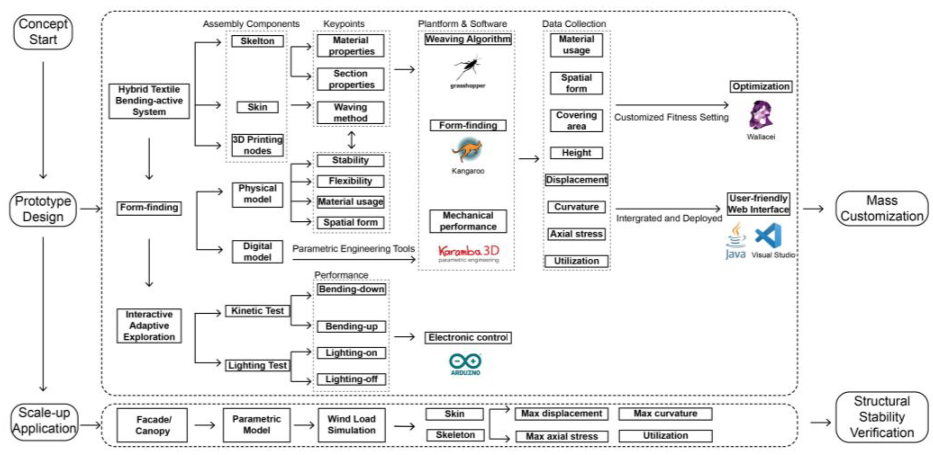
This section focuses on the material and methodology employed during the WO prototype design phase. Figure 2 illustrates the workflow of this stage, which involved both physical model testing and digital model simulations to conduct experiments and explorations.
Due to the limitations of the operating area and experimental equipment, a 1:10 scale demonstrator was constructed to test the stability, flexibility, and material usage of different weaving methods for generating WO prototype structures. Additionally, a single-board microcontroller system was integrated into the 1:10 physical model to verify the dynamic interactivity potential of different skin weaving methods.
The form-finding process for construction structures can be accomplished through both physical prototype models and digital simulations. The primary objective is to determine the equilibrium shape of the prestressed mesh, which serves as input for assessing the structural stability under external load conditions [36,37,38,39,40]. The parametric digital model used various computational design tools and platforms for form-finding, weaving algorithm development, and mechanical performance simulations.
Due to limited material mechanical property data for PolRe, we adopted parameters from polyethylene terephthalate (PET) in the actual computational process for form finding and mechanical performance analysis [41]. This decision is based on the similarity between PolRe and PET, as PolRe’s core is also made of PET material, albeit with enhanced strength of skin. Additionally, properties for GFRP were obtained by referencing existing research materials, including tensile strength and Young’s modulus and shear modulus [42,43].
Data on material usage, covering area, displacement, and other relevant parameters were collected through these simulations. The results were the foundation for subsequent multi-objective optimization, where customized fitness settings were employed to aid in design customization and optimization decisions. Moreover, using Java and Visual Studio allowed the simulation process to be implemented into an interactive web interface, simplifying, and visualizing the mass customization process.
In the scale-up application stage, we conducted simulations using Karamba to analyze the mechanical behavior of a parameterized textile facade composed of WO prototypes under horizontal wind loads. In the specific context of architectural applications, we adapted the dimensions and cross-sections of PolRe and GFRP while incorporating material parameters to perform more precise mechanical analysis calculations. This approach allowed us to theoretically validate the stability of this hybrid textile-bending active structure in the construction context. The detailed computational process and results will be presented in Section 4.3.

2.1. Bending-Active Skeleton

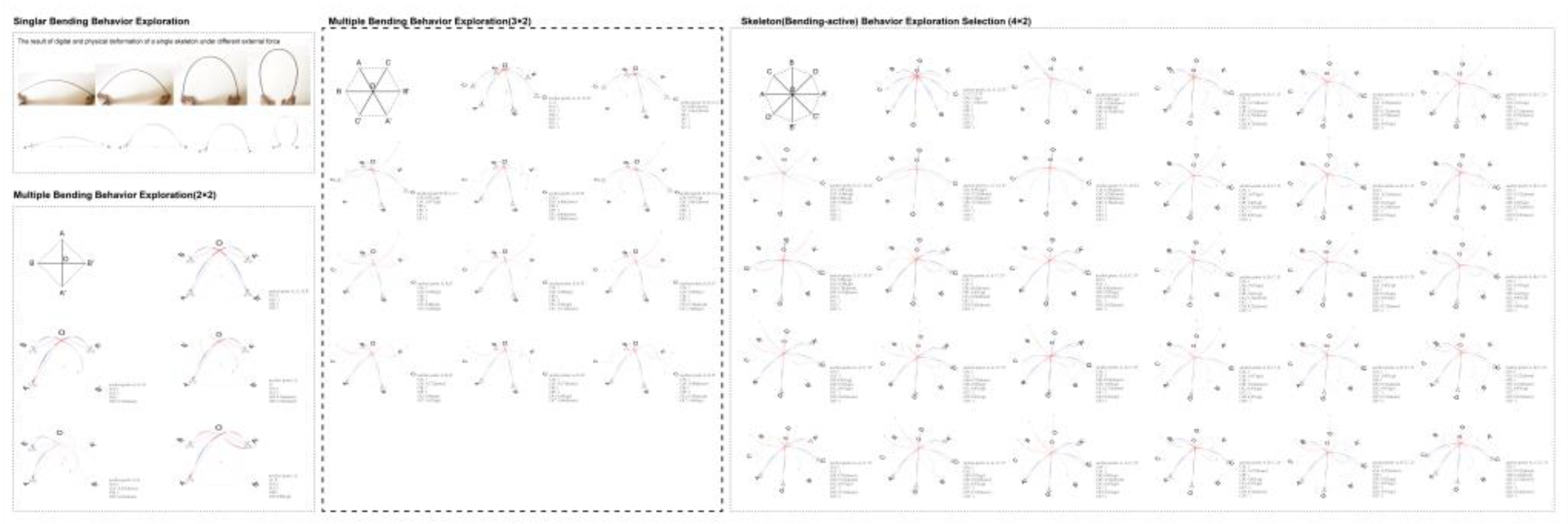
To satisfy high elasticity and strength ratios for skeletons in the WO prototype, the Ashby diagram was utilized to select the appropriate material [29]. GFRP was chosen for its bending-active properties after considering the material’s performance and availability. The research on skeleton bending initially began with single-bent rod elements and progressed to multi-bent rod elements (Figure 3). Kangaroo was employed for quick form-finding, while Karamba 3D facilitated accurate Finite Element Analysis (FEA). Ultimately, a planar hexagonal configuration formed by six bent rods was selected as the skeletons’ footprints for further investigations.

2.2. Form-Active Weaving Surface

The investigation into the weaving methods for both the skeleton and skin components of the WO prototype was carried out using both physical and digital models. The use of weaving-based surfaces offers advantages in terms of easy assembly and disassembly, as well as reducing the need for additional connection components.
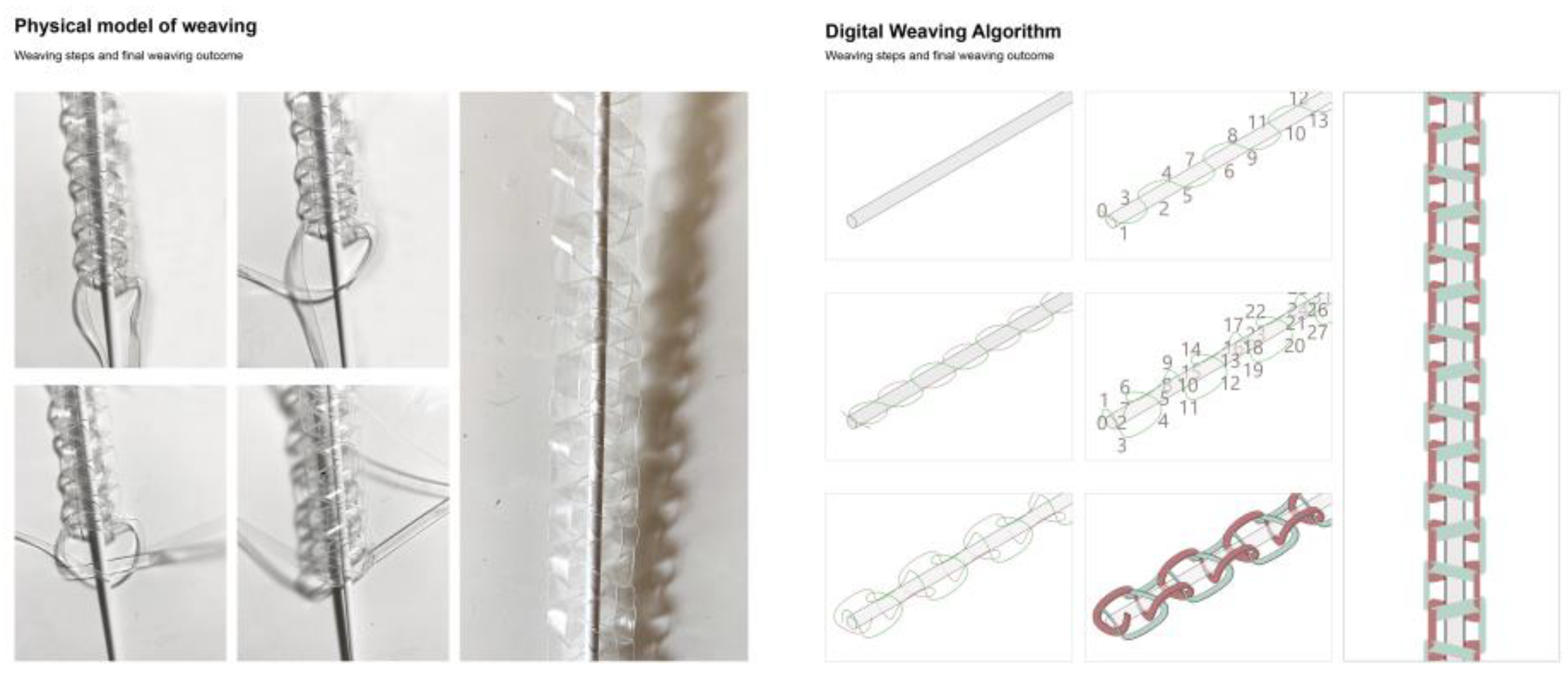
The weaving system on the bending-active skeleton utilized two PolRe@ fibers intertwined with each other. The logic of weaving on the skeleton surface in the physical model was translated into a weaving algorithm in Grasshopper (GH) for further exploration and analysis (Figure 4).
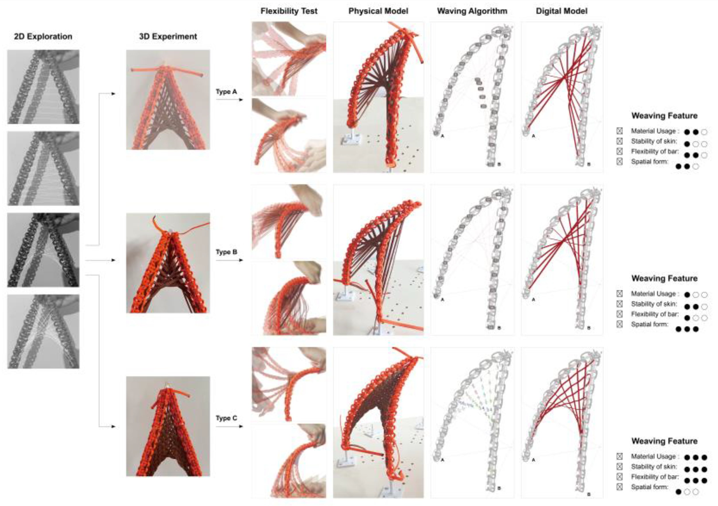
The experiment of form-active weaving skin expanded from 2D diagrams to 3D models, exploring three different weaving methods (A, B, and C). Manual bending experiments were performed on weaving models using methods A, B, and C to test flexibility and stability. The physical and digital models provided data on material usage and form configuration with different weaving methods while maintaining the same bending behavior of the skeleton (Figure 5). After evaluating parameters such as flexibility, stability, material usage, and spatial form, methods B and C were selected for subsequent overall application analysis and optimization experiments.

2.3. Computational-Aided Design

2.3.1. Form-Finding and Parametric Process

Parametric control played a crucial role in exploring the morphological variations of the WO prototype. After finalizing the skin’s weaving method and the skeleton’s footprints, the overall form-finding process was conducted. Figure 6 illustrates the parametric design workflow based on weaving method B.
The process started with using Kangaroo for fast form-finding, considering both the skin strain and skeleton elasticity. The next step involved using Karamba 3D to obtain rapid Finite Element Analysis (FEA) engineering performance results and to visualize the assembled WO components. Finally, GH tools were used to collect data on material usage, covering area, height, max displacement, max curvature, and other relevant parameters, which were then utilized in the subsequent optimization and customization process.
The parametric design process enabled the efficient generation of a wide variety of WO units by simply adjusting the input related to the skeleton’s load conditions. However, manually adjusting and selecting the WO form consumed significant computational time each time the input was changed. To streamline and expedite the customization process, there was a need for an optimized and user-friendly interface.
The input end of the GH battery pack allows for the adjustment and control of the length of each woven skin. Using the Kangaroo solver, we obtain preliminary form-finding results. This initial form serves as input for Karamba’s mechanical analysis, where we collect data such as axial stress displacement and utilization for various WO configurations. Additionally, information regarding the coverage area, height, and material usage can be derived from the form-finding process using the GH base calculator. In the subsequent multiple objective optimizations, we focus on data relevant to design objectives, particularly for temporary pavilions. This includes considerations such as available space, material usage, and maximum displacement. The weights of these three fitnesses are equally emphasized in the objective optimization process.

2.3.2. Multiple Objective Optimization

The optimization process utilized the evolutionary multi-objective optimization engine, Wallacei, within Grasshopper. This plugin allows users to set multiple different fitness criteria to cater to diverse requirements. The optimization process was demonstrated by optimizing the WO prototype as an assembled pavilion. Thus, the main objectives for this optimization were to ensure less material consumption, better mechanical performance, and sufficient available space for people to stay inside. To address these objectives, three constraints and fitness components were set (Figure 7):
  • Minimizing total material usage: a sum length of materials for weaving skin used in every 2 skeletons.
Total Material usage (m) = Material usage (AOC + A’OC’ + A’OB + AOB’ + BOC + B’OC’)
  • Better mechanical performance: minimal–maximum displacement assessed in Karamba 3D. The maximum displacement in Karamba 3d can be calculated using the following equation:
δ_max = 5qL4/384EI
(δ_max: maximum displacement at the center of the beam, q: uniform load, L: length of the beam, E: Young’s modulus of the beam material, I: moment of inertia of the beam’s cross-section.)
  • Sufficient available space: endure the ratio of the final form’s area to its height within the range of 0.058 to 2.444. The available space can be calculated using the following equation:
As = |H/A(c) − 0.058|+|H/A(c) − 2.44| − (2.44 − 0.058)
H/A(c) = H/Area
H/A(min) = 0.058
H/A(max) = 2.44
(As: available space for fitness 03, A(c): value of current state area, H: height, A: area)
The optimization results will be presented in Section 3, showcasing the iteration of optimization of the WO prototype that meets the specified criteria for an assembled pavilion.

2.4. User-Friendly Website Interface

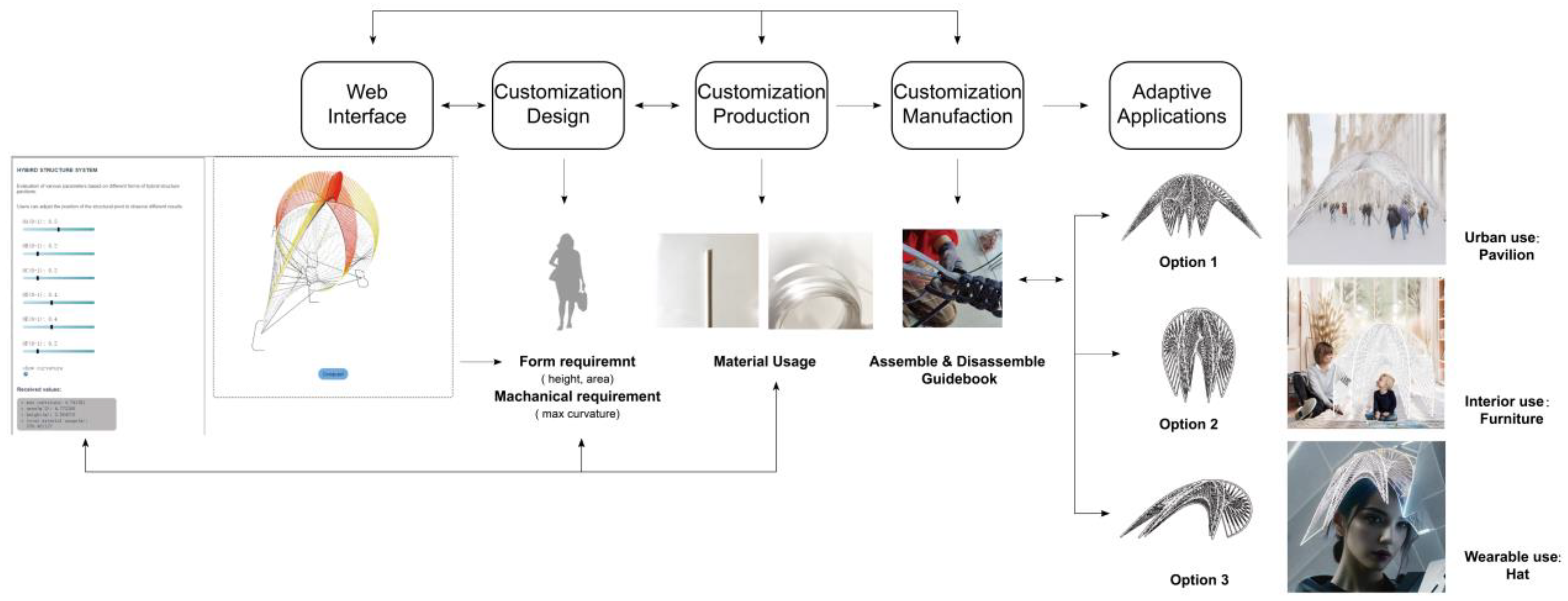
To enhance user experience and facilitate customization while obtaining essential parameters, we developed a user-friendly web interface. The process involves packaging complex algorithms using the Hops component in Grasshopper for Rhino7.0, developing web page functionality using the Java programming language in Visual Studio Code 2022, adding web components, and utilizing the Rhino Compute API to construct the web interface (Figure 8). Rhino Compute, acting as a Geometry Server, enables seamless integration and communication between Rhino and Visual Studio, ensuring efficient cross-platform compatibility. Through the web interface, users gain the convenience of directly adjusting input parameters. As a result, they receive real-time responses concerning the model and material usage data, which proves instrumental in informed design decision making. The user-friendly web interface thus plays a pivotal role in enhancing the accessibility and efficiency of the design process.

2.5. Interactive Electronic Control

The WO prototype further explored the potential of textile hybrid applications through single-board microcontroller kits for electronic interactive control. Utilizing Arduino board and Arduino IDE2.2.1 software, the study investigated dynamic interactivity and illuminated interactions (Figure 9). The experimentation involved various electronic components such as Ultrasonic Sensor, MG996R servo, and LED light sources. By programming the Arduino IDE in C++, the control of lighting switches or servo speed and direction was achieved by reading distance data from the Ultrasonic Sensor via the serial monitor, allowing interactive electronic control of the WO prototype.

3. Results

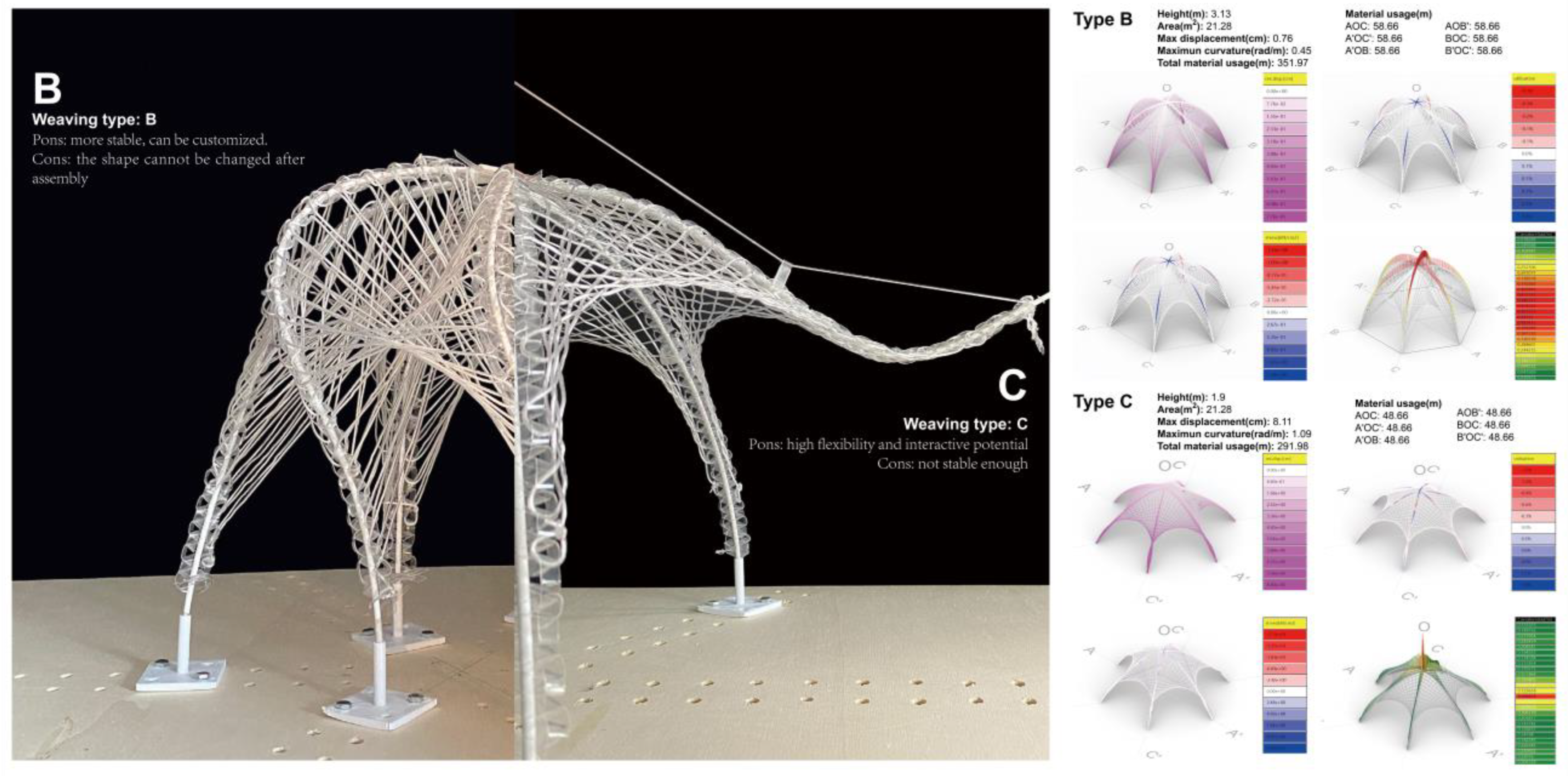
The study developed two prototypes, type B and type C, which applied the different weaving methods mentioned above (Figure 10, Left). We first compare the parameters of the results when the base area formed by the type B and type C is the same, that is, when the fulcrum positions of the skeletons are fixed (Figure 10, Right). From Figure 10, it can be observed that the max displacement formed by type C is about 8.11 cm, which is much larger than type B, which is 0.76 cm. The max utilization of B and C’s skeletons are 0.3% and 1.4%. Therefore, B is more stable than C. In addition, the heights of the internal space formed by B and C are 3.13 and 1.9 m, and the total weaving consumables are 351.97 m and 291.98 m. The binding force of C weaving method to the skeleton is not as strong as that of B. We also designed different experiments to further explore the characteristics of these two. According to their characteristics and potential, the specific application of these two prototypes is discussed.

3.1. Type B Prototype

3.1.1. Form-Finding and Results

In our physical model testing, we confirmed the prototype’s stability relying solely on skeleton elasticity and weaving constraints. To evaluate the overall stability of type B and type C structures, we conducted simulations using Karamba3D. The results, presented in Figure 10 (right) show that the type B weaving method exhibited superior stability compared to type C in maximum displacement and maximum curvature. Type B adopts weaving method B, which can effectively control the relative distance between the skeletons and provide higher stability for the whole structure. However, once this method is used, the result will be a fixed shape, and the skeleton will not have mobility.
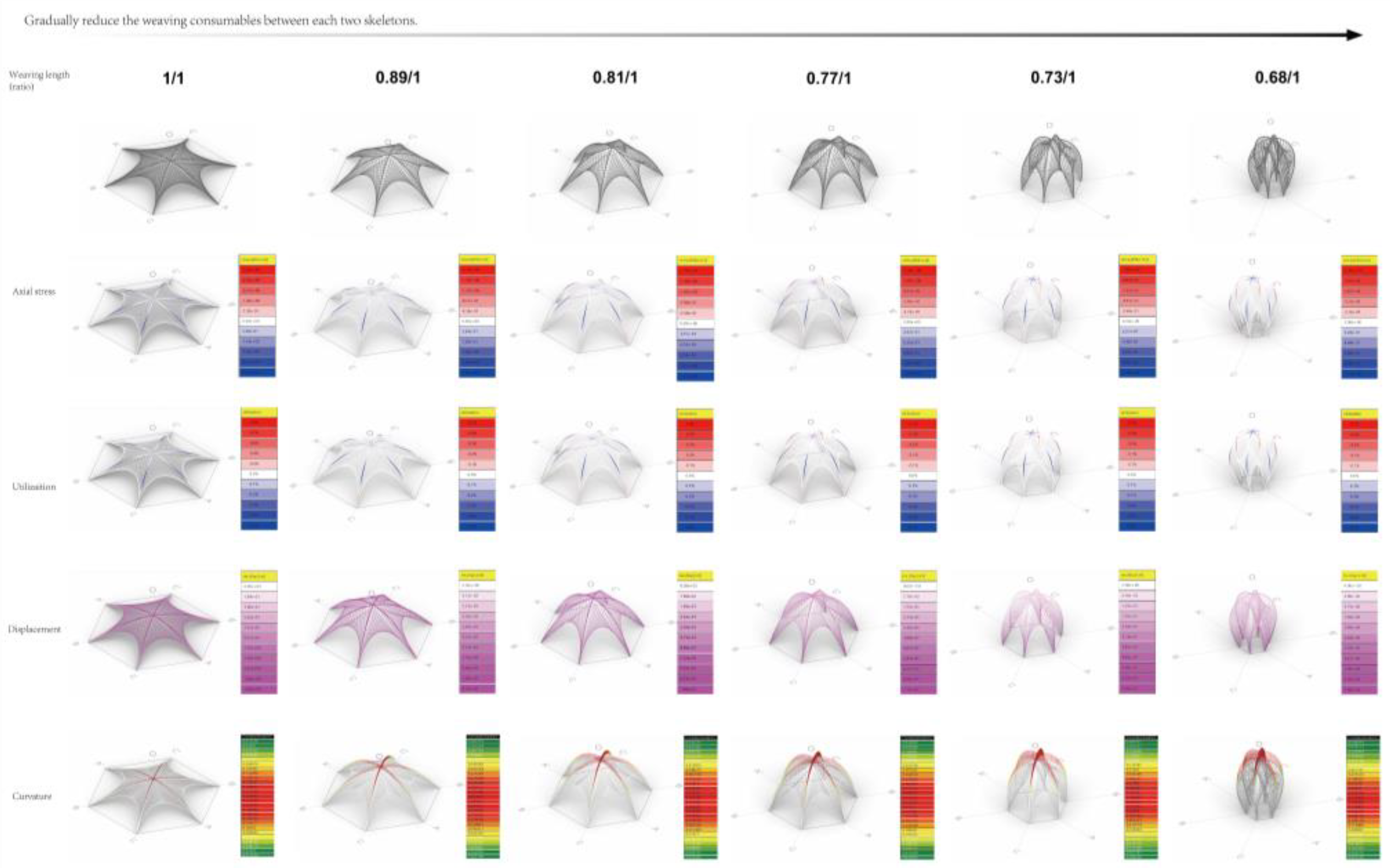
In the first experiment of type B, the length of the weaving material between every two skeletons is uniformly shrunk at the same time, and we can obtain the simulation results in GH as follows (Figure 11): Controlling the weaving material consumption can effectively change the shape of the prototype. We control the initial length to one and gradually adjust the ratio of “length” in Kangaroo to shrink the weaving length. Its prototype gradually changes from a relatively flat plane to resemble a cocoon. These weaving structures bind the entire skeleton. With shrinkage, the max curvature in the structure gradually increases (from 0.155 to 0.727), and the max displacement formed by the entire structure is gradually smaller (from 1.84 to 0.488 cm).
To further analyze the prototype, the second experiment is to change the weaving material between the two skeletons unevenly, to observe how the control of weaving will affect the final shape of the prototype. The results are impressive; stochastic control over the weave allows us to obtain more diverse variant states of the prototype. Figure 12 (Figure 12, Left) is only a part of the many variation results, but the actual situation is more abundant. This means that we can exploit this property for adaptive applications of this prototype. Each result gives real-time feedback of the following parameters: the actual weaving consumables between each group of skeletons, the total weaving consumables, the enclosed area, and the height of the internal space. We selected some variation results to further analyze their mechanical properties in Karamba 3D. Taking Figure 12 (Figure 12, Right) as an example, it can form a good internal space for human activities. The total weaving material is 358.46 m; the max displacement is 1.35 cm, which is within the acceptable range. The area and height of the inner space are 18.9 sqm and 3.1 m. That is to meet the scale of human activities.

3.1.2. Optimization and Results

In the above form-finding process, structural stability, weaving consumables, and whether the variation result can form a reasonable space to be used fare the parameters that need to be compared in each variation process. Simple comparisons cannot capture the changing rules of these parameters, so this research assumes whether there are certain specific shapes that can form an available space, making the variation results less consumable and more stable. By using Wallacei, a multi-objective optimization plug-in in Grasshopper, the research obtained the following results.
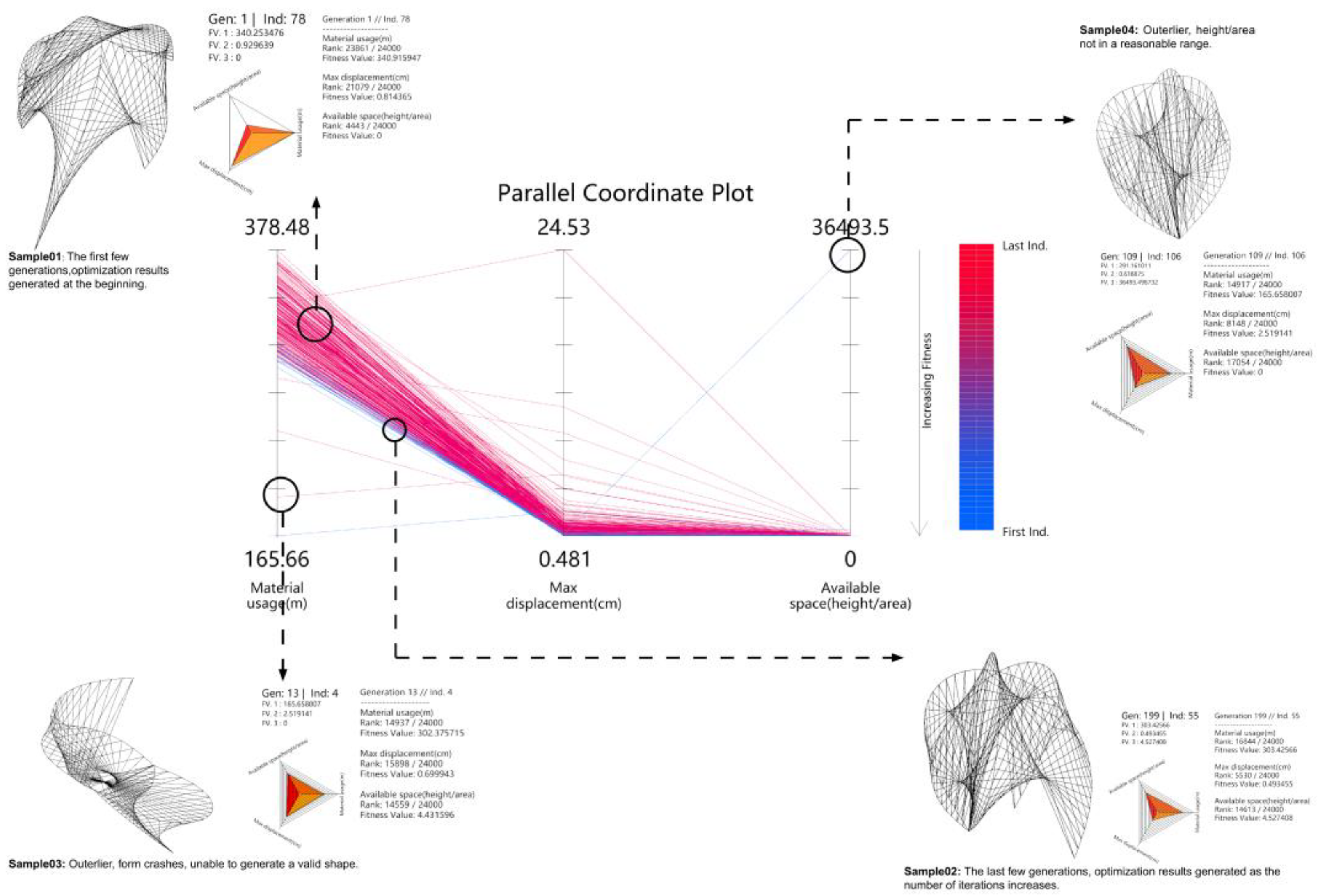
During the optimization process using Wallacei, we performed a total of 24,000 iterations at the beginning, which took 20 h. After around 4000 iterations, the stated outcome of multiple optimizations comes to the convergence criteria. As the number of iterations increases, the results of the last few iterations are closer to the ideal results in the three Fitness items (Figure 13: the red line represents the initial iteration, and the blue line represents the last few iterations). The optimization direction is to minimize the weaving consumables, minimize the structural displacement, and ensure that the available space is within a reasonable range.
By observing all the iteration results, the optimization process controls the available space (Fitness03) so that most of the results are at or close to the XY plane (Figure 14, Left). This means that the value of fitness03 is close to or equal to 0, from above in Section 2.3.2 (Figure 7), that is, the ratio of length to area of each result is between 0.058 and 2.444, which can be regarded as a space that can provide human activities. For weaving consumables, the final optimized results are concentrated between 29 and 305 m (Figure 14, Middle: the blue peak in graph). For the max displacement in the structure, the final optimized results are concentrated between 0.4 and 0.6 cm (Figure 14, Right: the blue peak in graph).
In the Parallel Coordinate Plot (PCP) graph, each iteration is a polyline, reflecting the size of its corresponding fitness value. The Parallel Coordinate Plot (PCP) obtained in this study will generally appear in the following situations (Figure 13): sample01 is from the first iterations’ result; sample02 is from the last iterations’ results. Sample03 shows an unexpected situation, and checking this result found that all the skeletons were flattened on a plane and could not form a valid shape. This may be due to the crash of the Kangaroo solver, so this study will not consider this case. Sample04 exemplifies a situation where the available area is seriously unsatisfied. The foot points of the generated shape all overlap at one point, making the shape unable to form an internal cavity and not enough to provide internal activity space.
Finally, we compare the result of the initial iteration with the last optimization. Taking Generation01 as an example (Figure 15, black line in the left), a total of 96 different results were obtained after deduplication (Figure S1). The shape of the prototype is closer to an exaggerated form. In these cases, the value of the material consumables and the structural displacement are relatively large. Observing the last iteration Generation199 (Figure 15, black line in the right), a total of 17 different results were obtained after deduplication (Figure S2). As the evolutionary direction moves closer to the fitness goal, the shape of each prototype is closer together, forming a similar cocoon shape. At the same time, the material consumables and structural stability are optimized compared to the original generation results.
All the optimization results are recorded in the form of an Excel table in Table S1. In this experiment, some more efficient prototypes were obtained through optimization, which will be an intuitive result in the selection of prototypes. However, considering the practical application, our ideal prototype is not some specific form but a variety of possibilities to meet the different needs in practical applications.

3.2. Type C Prototype

Dynamic Behavior Experiment and Results

Type C adopts weaving method C, which provides less stability than method B, but the advantage is that the woven prototype has the possibility of flexible movement with a single skeleton while maintaining its basic shape. Inspired by the structure of human fingers [44], we first restore the movement principle through a physical model (Figure 16, Left): Add a component that can constrain the control line in the middle of the skeleton, and change the lifting and gathering state of the skeleton by shrinking or relaxing the control line at the vertex. The movement of a single skeleton can be easily and flexibly controlled (Figure 16, Middle). Applying it to the entire structure, the simulation results are as follows (Figure 16, Right). We concluded that due to the difference in the weaving method, C provides limited constraints on its skeleton, allowing the skeleton to move freely to take advantage of the bending-active structure. Therefore, it has the potential to become a flexible structure in interactive and robot design [45].

3.3. Self-Combination Exploration

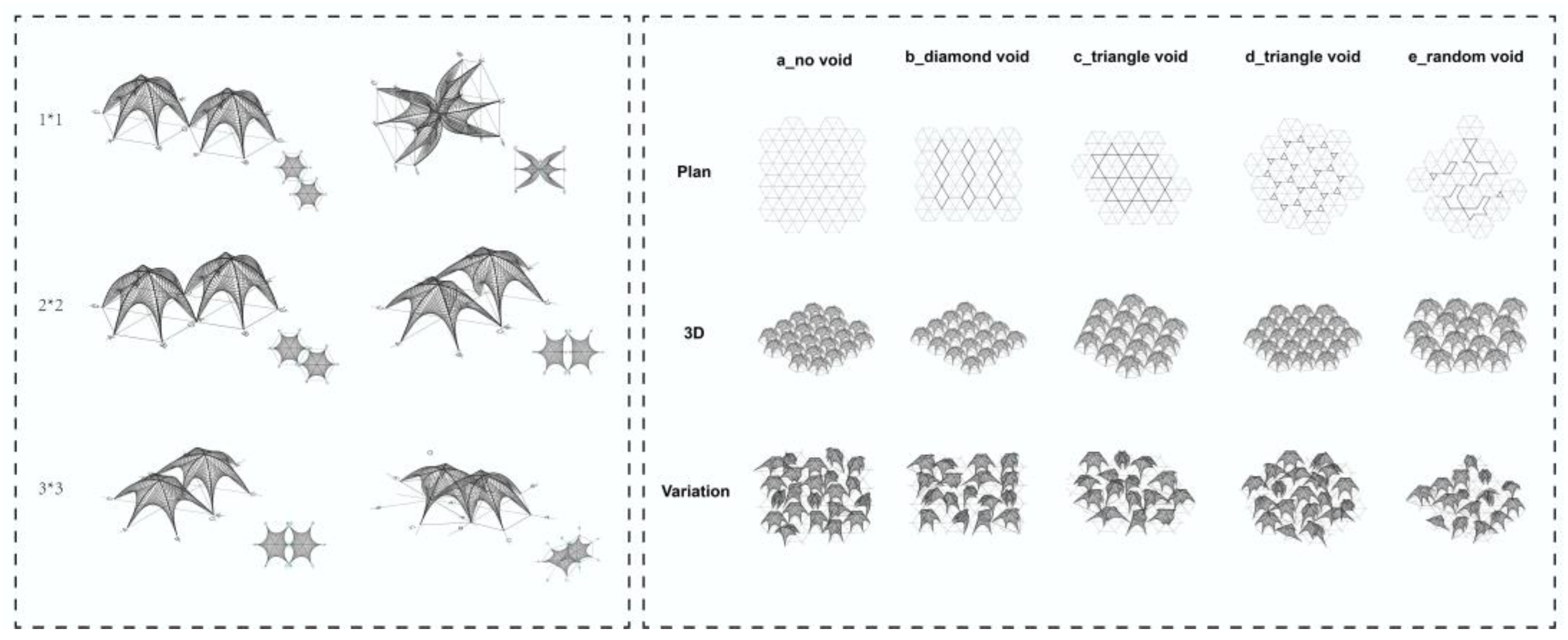
As an independent unit, WO has good adaptability, flexibility, a changeable shape, and shape controllability. In the modular design, it has the ability of various splicing with other units, which makes it have a very wide application range. The flexible self-combination capability was not discussed too much in this study, but it is worth noting that the prototype, as an independent module, has many possibilities to connect with other modules. The connection methods are mainly divided into the following (Figure 17, Left): two modules share one foot point; two modules can be connected through two different foot points; two modules are connected through up to three different foot points. The connection method and the changeable modules determine that the combination results will have many different changes, reflecting the flexibility and adaptability of the combination structure. In addition, the layout of the plan formed by the aggregation of many modules is also diverse in order to meet the venue construction of different temporary activities (Figure 17, Right). Considering the modular architectural form, this prototype is also meaningful and valuable.

4. Applications

The WO prototypes under the B and C weaving methods show different mechanical properties and development potential. This chapter will explore the application of WO prototypes based on this research from small-scale furniture decorations to architectural facades to large-scale urban installations.

4.1. Web Interface Assist Customization

With its stable structure and controllable shape, type B can be widely used in light devices that require customization [46]. We have developed a set of user-customized processes in this application scenario (Figure 18): Users adjust the slider on this interactive web to explore their desired shape, and the web page will provide real-time feedback on material usage and mechanical properties to assist in product construction. After the user’s order is generated, the manufacturer will send materials and assembly manuals to help the user complete the construction of the product. These materials will also be recycled at the end of the product’s life cycle. Variations of the prototype will have different sizes—large, medium, and small,—and they can be applied in various fields such as urban furniture, pavilions, interior decoration, and even clothing (Figure 18).

4.2. Interactive Demo

The type C weaving method is more flexible. The application based on this weaving method focuses on exploring the WO prototype for interacting with human behavior and the environment.
The dynamic results presented as photographs (Figure 19, Left, and Right up) demonstrate a demo-like experiment. Due to the size limitation, this model does not use real PolRe@ material but uses PVC wire instead. This experimental demo verified that the WO prototype’s interactive possibilities could be further improved into a mature product. In addition, the research also introduces the lighting system in terms of interaction (Figure 19, Middle and Right down). The weaving material was changed into an optical fiber tape in this demo, and the light source was at both ends of the weaving structure. In practical applications, materials can be selected based on specific needs, providing greater versatility.

4.3. Kinetic Façade

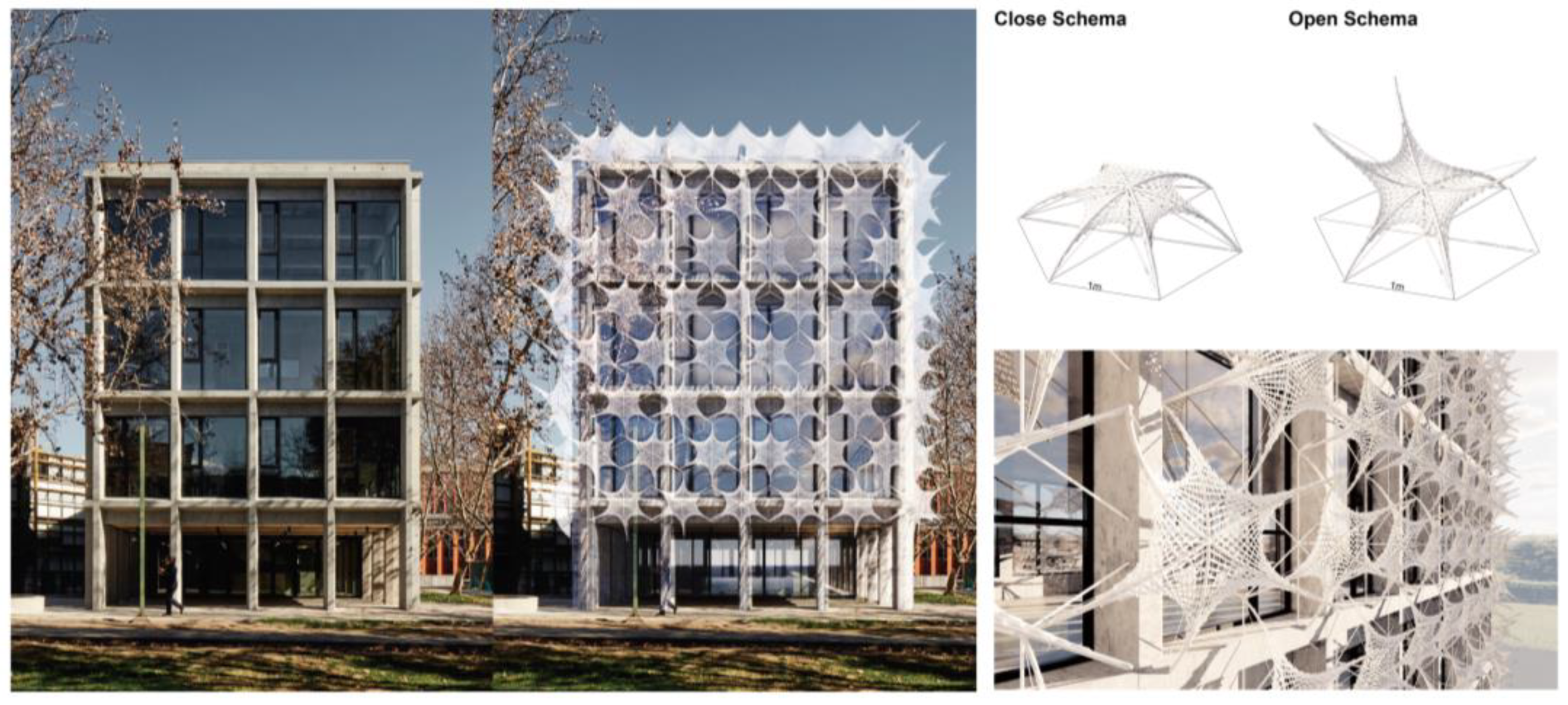
This application explores the potential of implementing a dynamic textile facade [47,48,49] using the WO prototype. As a practical example, we selected the Pedagogy in the Secondary Education School Universidad Católica and integrated the textile hybrid facade comprised of WO units onto the building’s elevation (Figure 20, Left). The WO modules can be opened or closed manually or automatically, offering aesthetic enhancements and practical sunshade functionalities. This dynamic feature adds an interactive dimension to the building’s facade, accommodating changing environmental conditions and user preferences.
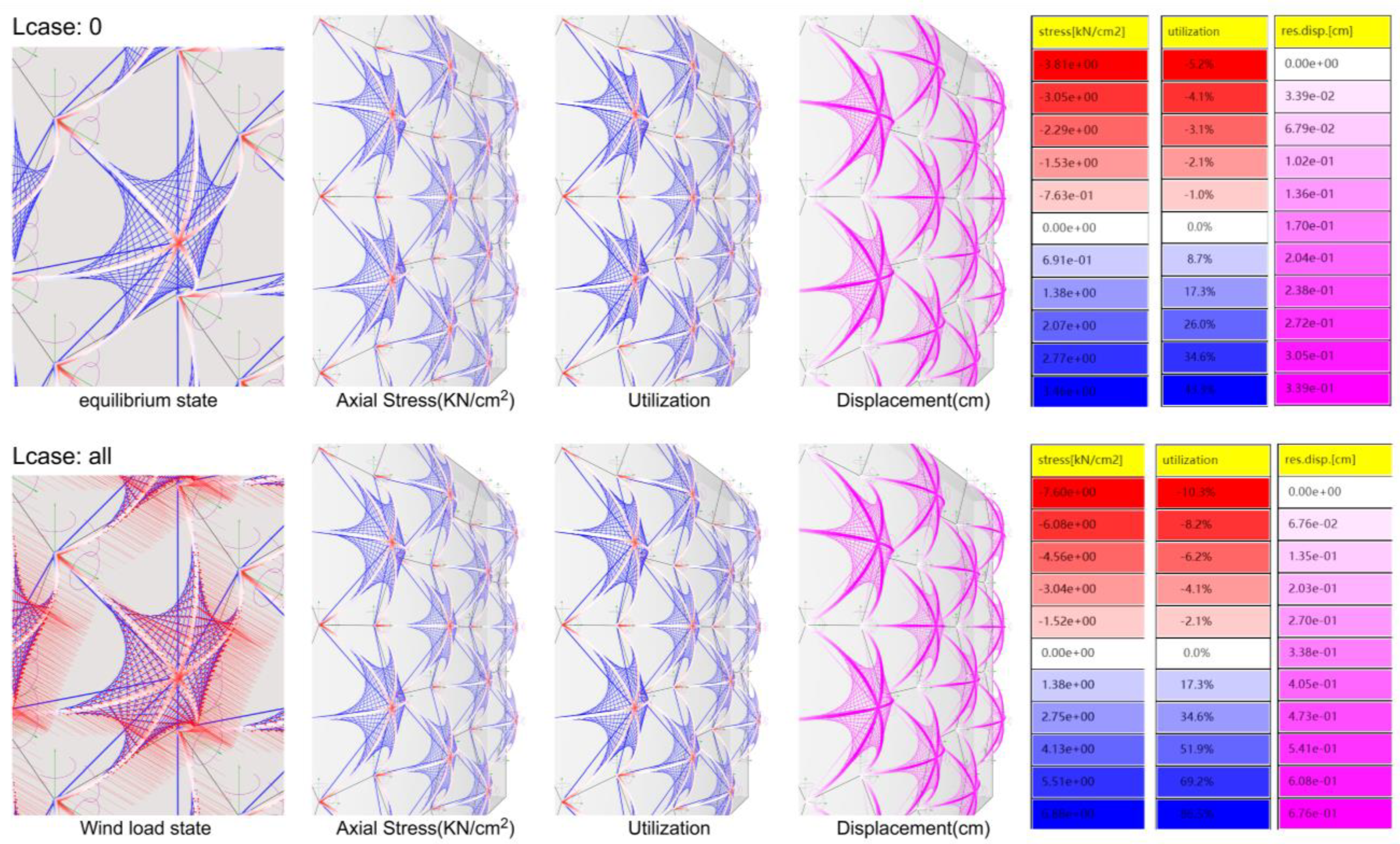
This chapter further verified the feasibility of the prototype in specific scenarios through mechanical simulation of the facade design. In order to simplify the calculation, we cut the simulation range into a building facade of 6 × 6 m. These 12 connected facade elements are considered as a structural whole for calculation. The focus of the simulation is to compare the stress in the skeleton and weaving system of the WO facade under normal state and wind load, as well as the deformation displacement of the whole structure. In the parametric structural engineering tool, Karamba 3D, we preset that the structure consists of three parts: control rope, GFRP skeleton, and weaving system. Detailed material selection and input parameters in Karamba 3D are as shown in Table 1.
During the simulation process, the stress conditions of each component and anchor points are shown in Figure 21, Left. Wind load is calculated with reference to such formula:
F = 0.00256 Cd V2A
(F = wind force (lb), Cd = drag coefficient, V = wind velocity (mi/h), A = projected area (ft2)) [50].
The wind speed of 24 m/s is used to test the designed adaptive structure. This value is obtained from Eurocode EN 1991-1-4:2005 [51], with action on the structures. Wind loads in the simulation will be applied in the direction perpendicular to the building facade. After calculation, the comparison of the value of stresses and the displacement in this structure between equilibrium and wind load can be seen in Figure 21. The maximum utilization in both states does not exceed 100%. Under the action of wind load, the maximum displacement of the structure is approximately 0.676 cm, which is far less than the maximum threshold allowed for structural deformation.
The maximum value of tensile stress in this weaving system is 3.02 kN/cm2, in control rope is 2.85 kN/cm2 (Table 2). The yield strength of PET is 5.52 kN/cm2, which means this weaving system can withstand relatively high wind speeds. The maximum value of the axial stress in the skeleton is 3.47 kN/cm2 (Table 2). The yield strength of GFRP is 45 kN/cm2. Through the above simulation and calculation, it can be seen that the structure as a whole can distribute high loads without crushing. It is feasible to apply this structure to building facades.

4.4. Adaptive Canopy

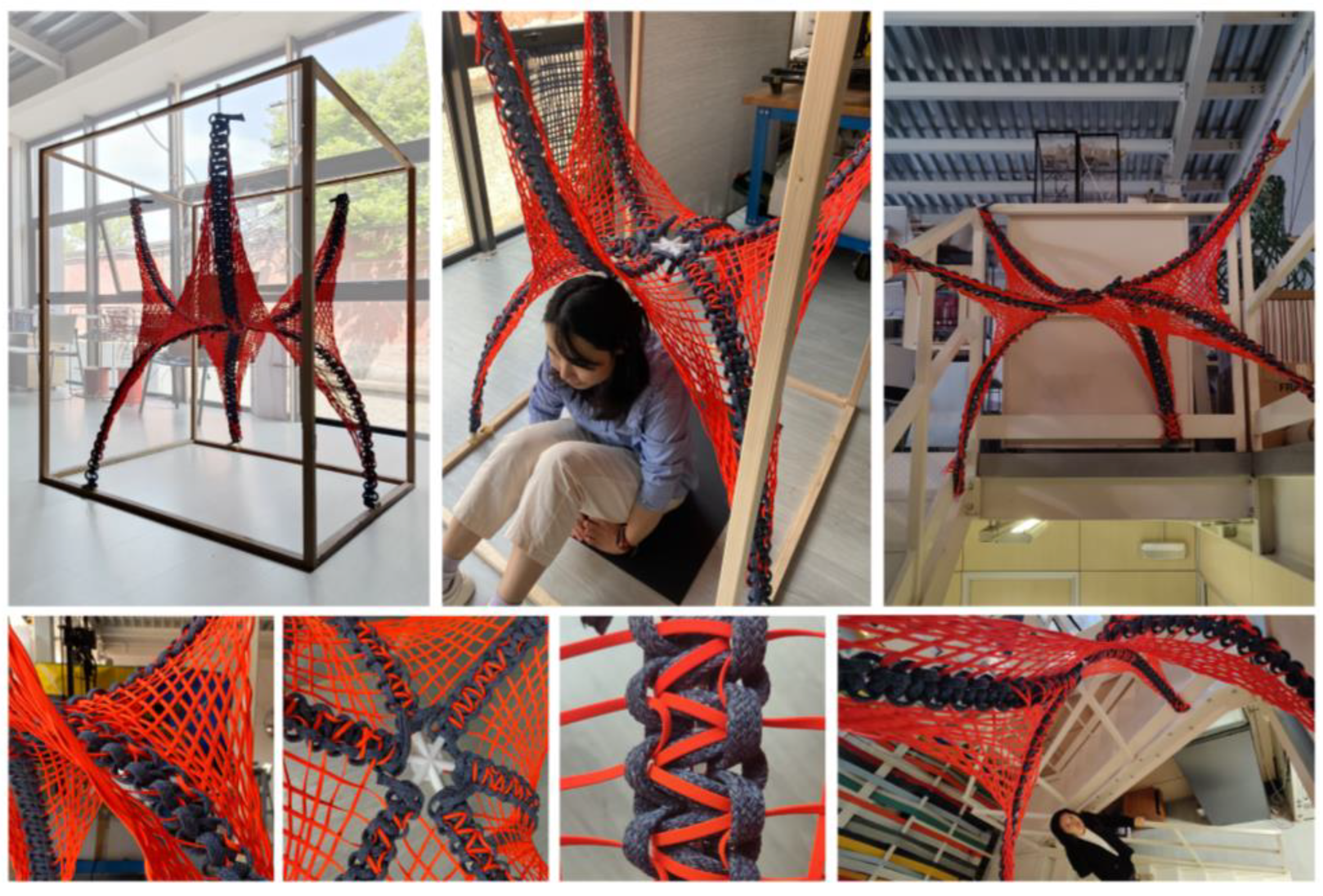
In the last application exploration, a 1:1 physical model of the WO prototype was fabricated using PolRe@ to explore its adaptive use in different indoor space types. The 1:1 WO model was installed in the open space and stairwell of Polimi Textiles Lab (Figure 22), forming furniture or an interior decoration ceiling for resting or viewing according to different space types. This successful implementation confirms the WO prototype’s adaptability for various indoor and outdoor spatial environments.

5. Discussion

Developing and designing the “Weaving Octopus” typology presents innovative approaches for sustainable and environmentally friendly textile temporal construction and decoration. However, there are limitations in the research that require further investigation and consideration.

5.1. Contribution

This research thoroughly explores and discusses the textile hybrid structure of bending-active and weaving. Unlike traditional weaving methods, this research creates a new weaving algorithm based on our irregular surface. Different weaving methods employed for the skin result in distinct dynamic behavioral characteristics, allowing users to choose suitable methods based on desired states.
This study develops two weaving methodologies with two distinct characteristics. “Weaving Octopus” (WO) demonstrates strong adaptability, excellent flexibility, ease of self-connection, and a wide range of controllable forms. Notably, WO fulfills the diverse needs of urban blank spaces and finds applications in installation design, interior design, and building facades.
The study establishes a comprehensive research-application workflow that begins with material research and progresses through physical experiments and computer simulations. Different application potentials are then explored based on the prototype’s characteristics. The research also culminates in developing a small interactive demo, a user-friendly web interface, and a 1:1 scale physical model to verify the prototype’s practical application potential. These experimental results are well implemented in practical applications.
From a life cycle perspective [27], prototypes in this study are sustainable. The woven skin and structural elements minimize connection joints and materials, enabling easy material recovery and recycling. The weaving technique allows convenient assembly and disassembly [26,52], with a parametric design flow ensuring precise control over the final effect and materials [46], significantly reducing waste and time costs. These solutions address the circular economy and environmental challenges of temporary lightweight architecture.

5.2. Limitation

Due to the manual hand weaving involved in this prototype, achieving precise control over the weaving accuracy is challenging. Additionally, the weaving methodology requires users to invest time in learning the techniques, limiting its universal applicability. Possible solutions could involve combining robotic arms for precise weaving manufacturing [53] or integrating virtual reality (VR), augmented reality (AR), and mixed reality (XR) technologies to assist users in achieving precise manufacturing [54].
The practical application of the prototype requires further consideration of specific details. For example, the detailed design of anchor points for outdoor installations and the ability to withstand snow and rain loads require examination. These factors need to be addressed to ensure the structural integrity and performance of the “Weaving Octopus” in outdoor environments.
Parametric tools and optimization software greatly aided the project’s research. However, to simplify the problem and facilitate the calculation, the optimization of the type B prototype does not traverse all the possibilities of variations. We think that the current iteration is basically enough for us to observe its optimization direction and draw rough conclusions. The prototype also did not take wind loads and other live loads into account during the Karamba 3D simulations. The mechanical analysis should be recalculated when considering different cases of application.

5.3. Future Work

This paper does not further explore the modular application of this prototype, but this paper presents some inspiring possibilities through simple simulations. In future in-depth research, it is necessary to consider the detailed and feasible connection methods between modules, the overall mechanical conditions of the aggregation results, the effective combination methods, and application scenarios between groups.
While this typology exhibits dynamic and variable potential, currently it lacks responsiveness to climatic conditions. Future research could focus on developing responses to solar forces and rain based on the dynamic behavior of the WO prototype. This would enable the realization of dynamic shading components, solar energy collection, and rainwater harvesting.

6. Conclusions

The research conducted on the “Weaving Octopus” typology confirms the feasibility and adaptivity of a textile hybrid system based on a bending-active structural system, achieved through innovative weaving methodologies. At the construction level, through specific facade applications, we have theoretically demonstrated the structural stability of the WO bending-active textile-hybrid structure. This offers a promising solution to address the diverse challenges faced by the world in terms of environmental concerns and human settlements. Moreover, it contributes significantly to advancing lightweight structural design and promoting sustainable practices in textile architecture.

Supplementary Materials

The following supporting information can be downloaded at: https://www.mdpi.com/article/10.3390/buildings13102413/s1, Figure S1: All the results from generation01; Figure S2: All the results from generation199; Table S1: Wallaice_24000results.

Author Contributions

Conceptualization, Z.C., S.Z., S.V. and A.Z.; Methodology, Z.C., S.Z. and S.V.; Software, Z.C. and S.Z.; Validation, Z.C. and S.Z.; Formal analysis, Z.C. and S.Z.; Investigation, Z.C. and S.Z.; Resources, Z.C. and S.Z.; Data curation, Z.C. and S.Z.; Writing—original draft, Z.C. and S.Z.; Writing—review & editing, Z.C., S.Z. and S.V.; Visualization, Z.C. and S.Z.; Supervision, S.V. and A.Z.; Project administration, A.Z.; Funding acquisition, A.Z. All authors have read and agreed to the published version of the manuscript.

Funding

This work was supported by DABC R&D founding and TextilesHUB laboratory of Politecnico di Milano.

Data Availability Statement

No new data were created.

Acknowledgments

We would like to thank the PolRe@ company and Textiles HUB Lab for their generous material and equipment support, which enabled us to carry out our experiments and prototype development.

Conflicts of Interest

The authors declare no conflict of interest.

References

  1. Popescu, M.; Rippmann, M.; Liew, A.; Reiter, L.; Flatt, R.J.; Van Mele, T.; Block, P. Structural design, digital fabrication and construction of the cable-net and knitted formwork of the KnitCandela concrete shell. Structures 2021, 31, 1287–1299. [Google Scholar] [CrossRef]
  2. De Vita, M.; Beccarelli, P.; Laurini, E.; De Berardinis, P. Performance Analyses of Temporary Membrane Structures: Energy Saving and CO2 Reduction through Dynamic Simulations of Textile Envelopes. Sustainability 2018, 10, 2548. [Google Scholar] [CrossRef]
  3. Shu, Q.; Middleton, W.; Dörstelmann, M.; Santucci, D.; Ludwig, F. Urban Microclimate Canopy: Design, Manufacture, Installation, and Growth Simulation of a Living Architecture Prototype. Sustainability 2020, 12, 6004. [Google Scholar] [CrossRef]
  4. Lienhard, J.; Schleicher, S.; Poppinga, S.; Masselter, T.; Milwich, M.; Speck, T.; Knippers, J. Flectofin: A hingeless flapping mechanism inspired by nature. Bioinspir. Biomim. 2011, 6, 045001. [Google Scholar] [CrossRef]
  5. Meiklejohn, E.; Hagan, B.; Ko, J. Rapid Sketching of Woven Textile Behavior: The Experimental Use of Parametric Modeling and Interactive Simulation in the Weaving Process. Comput. Aided Des. 2022, 149, 103263. [Google Scholar] [CrossRef]
  6. Sippach, T.; Dahy, H.; Uhlig, K.; Grisin, B.; Carosella, S.; Middendorf, P.J.P. Structural optimization through biomimetic-inspired material-specific application of plant-based natural fiber-reinforced polymer composites (NFRP) for future sustainable lightweight architecture. Polymers 2020, 12, 3048. [Google Scholar] [CrossRef]
  7. Zanelli, A.; Monticelli, C.; Viscuso, S. Closing the Loops in Textile Architecture: Innovative Strategies and Limits of Introducing Biopolymers in Membrane Structures. In Regeneration of the Built Environment from a Circular Economy Perspective; Della Torre, S., Cattaneo, S., Lenzi, C., Zanelli, A., Eds.; Springer International Publishing: Cham, Switzerland, 2020; pp. 263–276. [Google Scholar]
  8. Lüling, C.; Rucker-Gramm, P.; Weilandt, A.; Beuscher, J.; Nagel, D.; Schneider, J.; Maier, A.; Bauder, H.-J.; Weimer, T. Advanced 3D Textile Applications for the Building Envelope. Appl. Compos. Mater. 2021, 29, 343–356. [Google Scholar] [CrossRef]
  9. Cherif, C. Textile Materials for Lightweight Constructions; Springer: Berlin/Heidelberg, Germany, 2016. [Google Scholar]
  10. Monticelli, C.; Zanelli, A. Material saving and building component efficiency as main eco-design principles for membrane architecture: Case—Studies of ETFE enclosures. Archit. Eng. Des. Manag. 2021, 17, 264–280. [Google Scholar] [CrossRef]
  11. Gasparini, K. Digital Hybridisation in Adaptive Textiles for Public Space. Textiles 2022, 2, 436–446. [Google Scholar] [CrossRef]
  12. Mazzola, C.; Stimpfle, B.; Zanelli, A.; Canobbio, R. TemporActive Pavillion: First Loop of Design and Prototyping of an Ultra-lightweight Temporary Architecture. In Proceedings of the TensiNet Symposium 2019 “Softening the Habitats. Sustainable Innovation in Minimal Mass Structures and Lightweight Architectures”; Maggioli: Rimini, Italy, 2019; pp. 390–401. [Google Scholar]
  13. Ahlquist, S.; Lienhard, J.; Knippers, J.; Menges, A. Exploring Material Reciprocities for Textile-Hybrid Systems as Spatial Structures. In Proceedings of the Prototyping Architecture: The Conference Papers; The Building Centre Trust: London, UK, 2013; pp. 187–210. [Google Scholar]
  14. Boulic, L.; D’Acunto, P.; Bertagna, F.; Castellón, J.J. Form-driven design of a bending-active tensile façade system. Int. J. Space Struct. 2020, 35, 174–190. [Google Scholar] [CrossRef]
  15. Ahlquist, S.; Lienhard, J.; Knippers, J.; Menges, A. Physical and Numerical Prototyping for Integrated Bending and Form-active Textile Hybrid Structures. In Proceedings of the Rethinking Prototyping: Proceeding of the Design Modelling Symposium, Berlin, Germany, 30 September 2013; University of Stuttgart: Stuttgart, Germany; pp. 1–14. [Google Scholar]
  16. Lienhard, J.; Knippers, J.J.J.o.t.I.A.f.S.; Structures, S. Bending-active textile hybrids. J. Int. Assoc. Shell Spat. Struct. 2015, 56, 37–48. [Google Scholar]
  17. La Magna, R.; Fragkia, V.; Längst, P.; Lienhard, J.; Noël, R.; Šinke Baranovskaya, Y.; Tamke, M.; Ramsgaard Thomsen, M. Isoropia: An Encompassing Approach for the Design, Analysis and Form-Finding of Bending-Active Textile Hybrids. In Proceedings of IASS Annual Symposia; International Association for Shell and Spatial Structures (IASS): Madrid, Spain, 2018; pp. 1–8. [Google Scholar]
  18. Kamble, Z.; Behera, B.K. Sustainable hybrid composites reinforced with textile waste for construction and building applications. Constr. Build. Mater. 2021, 284, 122800. [Google Scholar] [CrossRef]
  19. Thomsen, M.R.; Tamke, M.; Deleuran, A.H.; Tinning, I.K.F.; Evers, H.L.; Gengnagel, C.; Schmeck, M. Hybrid tower, designing soft structures. In Modelling Behaviour: Design Modelling Symposium 2015; Springer: Berlin/Heidelberg, Germany, 2015; pp. 87–99. [Google Scholar]
  20. Millentrup, V.; Thomsen, M.R.; Nicholas, P. Actuated Textile Hybrids: Textile smocking for designing dynamic force equilibria in membrane structures. In Proceedings of the eCAADe: Architecture in the Age of the 4th Industrial Revolution, Porto, Portugal, 11–13 September 2019; pp. 521–530. Available online: https://ecaadesigradi2019.arq.up.pt/ (accessed on 6 August 2023).
  21. Mankus, M. Tactics for temporary uses of buildings and spaces in architecture. Typology and sociocultural value. Moksl. Liet. Ateitis Sci. Future Lith. 2015, 7, 132–140. [Google Scholar] [CrossRef]
  22. Ahlquist, S.; Ketcheson, L.; Colombi, C. Multisensory Architecture: The Dynamic Interplay of Environment, Movement and Social Function. Archit. Des. 2017, 87, 90–99. [Google Scholar] [CrossRef]
  23. Kim, M.-J.; Kim, B.-G.; Koh, J.-S.; Yi, H. Flexural biomimetic responsive building façade using a hybrid soft robot actuator and fabric membrane. Autom. Constr. 2023, 145, 104660. [Google Scholar] [CrossRef]
  24. Roxas, C.L.C.; Bautista, C.R.; Dela Cruz, O.G.; Dela Cruz, R.L.C.; De Pedro, J.P.Q.; Dungca, J.R.; Lejano, B.A.; Ongpeng, J.M.C. Design for Manufacturing and Assembly (DfMA) and Design for Deconstruction (DfD) in the Construction Industry: Challenges, Trends and Developments. Buildings 2023, 13, 1164. [Google Scholar] [CrossRef]
  25. Yazici, S.; Tanacan, L. Material-based computational design (MCD) in sustainable architecture. J. Build. Eng. 2020, 32, 101543. [Google Scholar] [CrossRef]
  26. ISO 20887:2020; Sustainability in Buildings and Civil Engineering Works—Design for Disassembly and Adaptability—Principles, Requirements and Guidance. ISO: Geneva, Switzerland, 2020.
  27. Roberts, M.; Allen, S.; Clarke, J.; Searle, J.; Coley, D. Understanding the global warming potential of circular design strategies: Life cycle assessment of a design-for-disassembly building. Sustain. Prod. Consum. 2023, 37, 331–343. [Google Scholar] [CrossRef]
  28. Dams, B.; Maskell, D.; Shea, A.; Allen, S.; Driesser, M.; Kretschmann, T.; Walker, P.; Emmitt, S. A circular construction evaluation framework to promote designing for disassembly and adaptability. J. Clean. Prod. 2021, 316, 128122. [Google Scholar] [CrossRef]
  29. Lienhard, J. Bending-Active Structures: Form-Finding Strategies Using Elastic Deformation in Static and Kinetic Systems and the Structural Potentials Therein. Ph.D. Thesis, University of Stuttgart, Stuttgart, Germany, 2014. [Google Scholar]
  30. Menges, A. Emergence: Morphogenetic Design Strategies; Wiley & Sons: Hoboken, NJ, USA, 2004; AD—Architectural Design; pp. 62–63. [Google Scholar]
  31. Alpermann, H.; Lafuente Hernández, E.; Gengnagel, C. Case-Studies of Arched Structures Using Actively-Bent Elements. In Proceedings of the IASS-APCS Symposium: From Spatial Structures to Space Structures, Seoul, Korea, 21 May 2012. [Google Scholar]
  32. Ahlquist, S.; Menges, A. Frameworks for Computational Design of Textile Micro-Architectures and Material Behavior in Forming Complex Force-Active Structures. In Proceedings of the ACADIA 2013 Conference, Waterloo, Belgium, 24 October 2013; pp. 281–292. [Google Scholar]
  33. Lienhard, J.; Eversmann, P. New hybrids—From textile logics towards tailored material behaviour. Archit. Eng. Des. Manag. 2021, 17, 169–174. [Google Scholar] [CrossRef]
  34. Lienhard, J.; Ahlquist, S.; Knippers, J.; Menges, A. Extending the Functional and Formal Vocabulary of Tensile Membrane Structures through the Interaction with Bending-Active Elements. In Proceedings of the Tensinet Symposium, Istanbul, Turkey, 2 December 2013. [Google Scholar]
  35. Ahlquist, S. Sensory material architectures: Concepts and methodologies for spatial tectonics and tactile responsivity in knitted textile hybrid structures. Int. J. Archit. Comput. 2016, 14, 63–82. [Google Scholar] [CrossRef]
  36. Linkwitz, K. Formfinding by the “direct approach” and pertinent strategies for the conceptual design of prestressed and hanging structures. Int. J. Space Struct. 1999, 14, 73–87. [Google Scholar] [CrossRef]
  37. Linhard, J.; Bletzinger, K.-U. “Tracing” the equilibrium—Recent advances in numerical form finding. Int. J. Space Struct. 2010, 25, 107–116. [Google Scholar] [CrossRef]
  38. Veenendaal, D.; Block, P. An overview and comparison of structural form finding methods for general networks. Int. J. Solids Struct. 2012, 49, 3741–3753. [Google Scholar] [CrossRef]
  39. Argyris, J.H.; Angelopoulos, T.; Bichat, B. A general method for the shape finding of lightweight tension structures. Comput. Methods Appl. Mech. Eng. 1974, 3, 135–149. [Google Scholar] [CrossRef]
  40. Maurin, B.; Motro, R. The surface stress density method as a form-finding tool for tensile membranes. Eng. Struct. 1998, 20, 712–719. [Google Scholar] [CrossRef]
  41. Mikail, O. Mechanical and Thermal Properties of HDPE/PET Microplastics, Applications, and Impact on Environment and Life. In Advances and Challenges in Microplastics; El-Sayed, S., Ed.; IntechOpen: Rijeka, Croatia, 2023; Chapter 5. [Google Scholar]
  42. Gao, H.; Sun, Y.; Jian, J.; Dong, Y.; Liu, H. Study on mechanical properties and application in communication pole line engineering of glass fiber reinforced polyurethane composites (GFRP). Case Stud. Constr. Mater. 2023, 18, e01942. [Google Scholar] [CrossRef]
  43. Smits, J. Fiber-Reinforced Polymer Bridge Design in the Netherlands: Architectural Challenges toward Innovative, Sustainable, and Durable Bridges. Engineering 2016, 2, 518–527. [Google Scholar] [CrossRef]
  44. Lurie-Luke, E. Product and technology innovation: What can biomimicry inspire? Biotechnol. Adv. 2014, 32, 1494–1505. [Google Scholar] [CrossRef]
  45. Schleicher, S. Bio-Inspired Compliant Mechanisms for Architectural Design: Transferring Bending and Folding Principles of Plant Leaves to Flexible Kinetic Structures; University of Stuttgart: Stuttgart, Germany, 2015. [Google Scholar]
  46. Bonev, M.; Hvam, L.; Clarkson, J.; Maier, A. Formal computer-aided product family architecture design for mass customization. Comput. Ind. 2015, 74, 58–70. [Google Scholar] [CrossRef]
  47. Hosseini, S.M.; Mohammadi, M.; Rosemann, A.; Schröder, T.; Lichtenberg, J. A morphological approach for kinetic façade design process to improve visual and thermal comfort: Review. Build. Environ. 2019, 153, 186–204. [Google Scholar] [CrossRef]
  48. Barozzi, M.; Lienhard, J.; Zanelli, A.; Monticelli, C. The Sustainability of Adaptive Envelopes: Developments of Kinetic Architecture. Procedia Eng. 2016, 155, 275–284. [Google Scholar] [CrossRef]
  49. Hosseini, S.M.; Fadli, F.; Mohammadi, M. Biomimetic Kinetic Shading Facade Inspired by Tree Morphology for Improving Occupant’s Daylight Performance. J. Daylighting 2021, 8, 65–85. [Google Scholar] [CrossRef]
  50. Kabošová, L.; Kormaníková, E.; Kmeť, S.; Katunský, D. Shape-Changing Tensegrity-Membrane Building Skin. In Proceedings of the MATEC Web of Conferences; EDP Sciences: Les Ulis, France, 2020; p. 00046. [Google Scholar]
  51. EN 1991-1-4; 2005: Eurocode 1: Actions on Structures—Part 1–4: General Actions—Wind Actions. European Standard Committee: Brussel, Italy, 2005.
  52. Cheshire, D. The Handbook to Building a Circular Economy; Routledge: New York, NY, USA, 2021. [Google Scholar]
  53. Brugnaro, G.; Baharlou, E.; Vasey, L.; Menges, A. Robotic Softness: An Adaptive Robotic Fabrication Process for Woven Structures. In Acadia 2016 Posthuman Frontiers: Data, Designers, and Cognitive Machines, Proceedings of the 36th Annual Conference of the Association for Computer Aided Design in Architecture Paperback, Ann Arbor, Michigan, 22 October 2016; Acadia: Ann Arbor, MI, USA, 2016. [Google Scholar]
  54. Stals, A.; Caldas, L. State of XR research in architecture with focus on professional practice—A systematic literature review. Archit. Sci. Rev. 2020, 65, 138–146. [Google Scholar] [CrossRef]
Figure 1. Left: WO conceptual sketches for adaptive use in urban scale. Right: WO conceptual physical models applied in different scenarios (on the ground, between two walls, and in the corner).
Buildings 13 02413 g001
Figure 2. The working flowchart.
Buildings 13 02413 g002
Figure 3. Left up: The physical and digital form-finding experiments for singular skeletons. Left down: The digital form-finding experiments of 2 * 2 skeleton. Middle: The digital form-finding experiments of 2 × 3 skeleton (selected). Right: The digital form-finding experiments of 2 × 4 skeleton.
Buildings 13 02413 g003
Figure 4. Weaving method on the skin (Left: physical model, Right: digital model), number in the right figure shows the sequent of the list of the weaving algorithm.
Buildings 13 02413 g004
Figure 5. Weaving method on skin with 3 different weaving method A, B and C.
Buildings 13 02413 g005
Figure 6. Parametric control flow exampled with weaving method B.
Buildings 13 02413 g006
Figure 7. Constraints and fitness setting of the optimization process.
Buildings 13 02413 g007
Figure 8. Workflow to build a user-friendly web interface.
Buildings 13 02413 g008
Figure 9. Workflow to integrate interactive electronic control system into the Weaving Octopus prototype.
Buildings 13 02413 g009
Figure 10. Left: The physical model comparison between prototype B and prototype C. Right: The structure simulation comparison of prototype B and prototype C in terms of displacement, utilization, stress, and curvature.
Buildings 13 02413 g010
Figure 11. Gradually reduce the weaving consumables between the two skeletons.
Buildings 13 02413 g011
Figure 12. Left: Form variation. Input: material usage for each two skeletons. Output: form/height/area/curvature/displacement of the prototype. Right: Taking one of the variations as an example for further analysis.
Buildings 13 02413 g012
Figure 13. Parallel Coordinate Plot (PCP) graph of optimization results.
Buildings 13 02413 g013
Figure 14. Left: 3D plot graph. X-Fittness01: material usage; Y-Fittness02: max displacement in the structure; Z-Fittness03: available space. Middle: standard Deviation Graph of fittness01. Right: standard Deviation Graph of fittness02.
Buildings 13 02413 g014
Figure 15. Left: Result from generation 01. Right: Result from generation 199.
Buildings 13 02413 g015
Figure 16. Left: Skeleton movement principle and experiment. Middle: Single skeleton movement effect display. Right: Physically simulate the motion state of the skeleton on the entire structure.
Buildings 13 02413 g016
Figure 17. Variations of self-combination and variations of layout configuration.
Buildings 13 02413 g017
Figure 18. Customization workflow through web interface.
Buildings 13 02413 g018
Figure 19. Dynamic and lighting interactive system display.
Buildings 13 02413 g019
Figure 20. The application of the interactive system on the building façade.
Buildings 13 02413 g020
Figure 21. Comparison of the stress on the facade system under normal state (Lcase: 0) and wind load (Lcase: all).
Buildings 13 02413 g021
Figure 22. The 1:1 scaled-up model in Polimi Textiles HUB Lab.
Buildings 13 02413 g022
Table 1. Material selection and input parameters in Karamba 3D.
Element (Material)Diameter (d) or Width (w) & Thickness (h) [cm]Specific Weight Gamma (KN/m3)In-Plane Shear Modulus G12 (KN/cm2)Transverse Shear Modulus G31, G32 (KN/cm2)Yield Strength fy1, fy2 (KN/cm2)Tensile Strength ft1, ft2 (KN/cm2)Compressive Strength fc1, fc2 (KN/cm2)
Skeleton (GFRP, orthotropic)d = 3E1 = 3656.9 E2 = 1092.4102610264574−3112.3
Weaving system/Control rope (PET, isotropic)w = 0.4/w = 0.8 h = 0.1E1 = E2 = 109.552.552.55.525.52−9.8
Table 2. Comparison of results of different structural elements under normal state and wind loads.
Element (Material)Max Axial Stress (KN/cm2) Lcase0/Lcase1Max Bending Moment (KNm) Lcase0/Lcase1Max Utilization (%) Lcase0/Lcase1Max
Displacement (cm) Lcase0/Lcase1
Skeleton (GFRP, orthotropic)3.446532/3.477179±0.095258/±0.96230.084179/0.0839350.3394/0.3363
Weaving system (PET, isotropic)3.029832/3.0237270/00.765444/0.7678420.3394/0.3363
Control rope (PET, isotropic)2.858931/2.8567770/00.408419/0.4081110.2729/0.2723
Disclaimer/Publisher’s Note: The statements, opinions and data contained in all publications are solely those of the individual author(s) and contributor(s) and not of MDPI and/or the editor(s). MDPI and/or the editor(s) disclaim responsibility for any injury to people or property resulting from any ideas, methods, instructions or products referred to in the content.