Article

Evaluation of the Thermal Performance of Fly Ash Foam Concrete Containing Phase Change Materials (PCMs)

1
Department of Architecture, College of Engineering, Nihon University, Koriyama 963-8642, Japan
2
Institute of Construction and Building Materials, Technical University of Darmstadt, Franziska-Braun-Str. 3, 64287 Darmstadt, Germany
*
Author to whom correspondence should be addressed.
Buildings 2023, 13(10), 2481; https://doi.org/10.3390/buildings13102481
Submission received: 1 September 2023 / Revised: 20 September 2023 / Accepted: 28 September 2023 / Published: 29 September 2023

Abstract

:
The aim of this study was to assess the characteristics of fly ash foam concrete containing two varying temperature ranges of microencapsulated phase change materials (PCMs): PCM28D (26–30 °C) and PCM43D (41–45 °C). In total, five different fly ash foam concrete samples were prepared, and the unit weight of cement was substituted with varying percentages of PCM (0%, 10% and 30%). As a result, differential scanning calorimetry (DSC) analysis revealed that PCM43D-30% exhibited a heat storage capacity of 45.32 °C and 37.89 °C with 42.87 J/g and 41.01 J/g in its liquid and solid phases, respectively. Furthermore, thermocycle analysis indicated that PCM43D-30% maintained the temperature within the stated phase change range for a duration of 7 h. In conclusion, the incorporation of PCMs (28D and 43D) in fly ash foam concrete shows promise in reducing indoor temperature fluctuations, thereby improving energy efficiency. The improved thermal performance can be suitable for various applications such as inner and outside walls of energy-efficient construction designs.

1. Introduction

The usage of energy in construction has become a demanding concern because of rising living standards and the increasing demand for heating and cooling. The International Energy Agency [1] reported that the construction field already occupies over one third of the world’s energy usage, so this proportion will rise even further in the next 50 years, particularly in residential buildings [2]. Therefore, there is an urgent need to decrease cooling and heating loads in construction and enhance energy efficiency.
There are multiple options to minimize cooling and heating loads in buildings [3,4,5]. One of the promising solutions to this growing issue is the inclusion of renewable energy sources into the construction field. By using solar thermal energy, for example, it is possible to decrease cooling and heating energy demands. In these regards, the incorporation of phase change materials (PCMs) has been initiated as a promising approach due to their remarkable ability to reserve and radiate thermal energy. The phase transition process of PCMs, which involves melting and solidifying states, allows them to operate as a thermal comfort system. When the ambient room temperature increases, the PCM accumulates energy before transitioning from a liquid to a solid state, and as temperature decreases, it solidifies, releasing the stored energy back into the environment [6]. It is said that this process makes it possible to create and maintain acceptable thermal comfort in residential buildings.
Within the building sector, the integration of PCMs’ phase change properties offers various applications, such as incorporating these materials into walls, roofs and floors to regulate indoor temperatures effectively. Two commonly used methods for PCM integration are direct impregnation and microencapsulation. The first, the direct impregnation method, involves absorbing PCMs into porous aggregates, but it can lead to PCM leakage and reduced thermal storage capacity [7]. The second method, microencapsulation, addresses this issue by covering PCMs in protective shells, maintaining their properties during the heating and cooling cycle [8]. However, microcapsules of PCMs have a significant drawback, as they crack during the mixing process. Because the protective shell of PCMs is composed of a polymer with limited mechanical stiffness, microencapsulated PCMs can be damaged. As was recorded in a number of studies, a number of microcapsules of PCMs were damaged [9,10,11]. Ref. [12], which evaluated the durability of self-compacting concrete incorporating microencapsulated PCMs, observed large numbers of broken microcapsules. From their findings, it can be suggested that microencapsulated PCMs are a sensitive soft material and have a lower density than concrete, which contains high-density aggregates. PCM microcapsules can be easily damaged by shear stress when mixed with conventional concrete containing high-density raw materials. Such damage results in substantial energy loss.
To address this issue and prevent disfigured PCM shells during mixing, two factors should be considered. First, using low-density materials, such as foam and fly ash, in concrete composites could help prevent cracking. Unlike conventional concrete, foamed concrete typically signifies lightweight concrete characterized by a notably lower density, increased porosity and reduced thermal conductivity [13,14,15,16]. Because of its substantial number of air voids and its lightweight properties, foamed concrete is an effective exterior wall insulation material [7,16,17]. Second, choosing an appropriate mixer also helps prevent cracking. It is also important to use an appropriate mixer to avoid such damage, and the OM mixer is claimed to be the most suitable option because, instead of stirring blades, it has a flexible rubber ball that ensures that the PCM particles are mixed homogeneously without any damage [18].
Regardless of the continuous effort in incorporating PCMs into building envelopes, it remains crucial to choose the appropriate PCM that suits different temperature ranges. It is noted that not all PCMs are suitable for thermal storage in building applications. PCMs must meet two key requirements: a suitable latent heat capacity and melting temperature [19]. The heat storage capacity of PCMs is closely related to their latent heat capacity, which measures the thermal energy absorbed during a phase transition. Researchers have primarily focused on PCMs with temperature ranges from 20 °C to 32 °C, as these temperatures align with optimal human comfort levels.
However, there are few researchers who have sought to explore PCMs with higher temperature ranges and expand their potential applications. PCMs with higher temperature ranges, between 40 °C and 50 °C, can be used in regions with hot climates to reduce heat transfer from outside and reduce the excessive temperatures of external walls. For example, in one study [20], a thermal analysis was conducted on building bricks with PCMs to be used in hot weather conditions. The melting point of the PCM used as bricks in this study is 47 °C. There was also an experimental study [21] in which the authors incorporated PCMs that have a melting point of 44 °C. The results of these studies suggest that PCMs displaying higher melting points could be useful in extreme hot weather conditions.
This study aimed to determine the energy-saving potential of two types of microencapsulated PCMs (28D and 43D) integrated into fly ash foam concrete, investigating their material properties and thermal behavior. These experiments contribute to the understanding of phase change phenomena and could have practical implications for enhancing indoor comfort and decreasing cooling and heating energy demands. These findings are also fundamental for further large-scale experiments on real buildings in different environmental conditions.
This study comprises four main sections: The Section 1 introduces the concept of PCMs and outlines methodologies employed for their integration into cement structures. The Section 2 provides an overview of basic material properties, incorporating both mechanical and thermal characteristics, along with the methods used for their assessment. The Section 3 extensively elaborates on experimental findings and engages in a detailed discussion regarding outcomes. The Section 4 offers comprehensive conclusions summarizing the main findings derived from this experimental research.

2. Materials and Methods

2.1. Materials

In this study, two varieties of microencapsulated PCMs (PCM28D and PCM43D) were used. The melting temperature of PCM28D ranged between 26 and 30 °C, and that of PCM43D ranged between 41 and 45 °C [22]. The specifications of these PCMs are as shown in Table 1, provided by the manufacturers. Apart from PCMs, rapid-hardening cement (RHC, Table 2) and type 2 fly ash, as illustrated in Table 3, meeting the requirements of [23], were used as the main dry materials. Additionally, the following admixtures were added. One of the additives was a water-reducing agent called Mighty 3000H, produced by Koa manufacturing in Tokyo, Japan. This additive was employed to enhance the workability of foam concrete. Moreover, in order to maintain the formation structure of the foam when incorporated into cement mortar, Drexel was also used as a foaming agent.

2.2. Mix Proportions

The dimensions of the samples were 40 mm × 40 mm× 160 mm, and all samples were mixed with two distinct varieties of microencapsulated PCMs. PCMs were employed to substitute 0%, 10% and 30% of the unit weights of cement, resulting in the preparation of a total of five samples (Table 4). Earlier studies indicated that the direct incorporation of PCMs into cementitious composites can lead to potential damage to PCM particles during the mixing process [12]. The OM mixer is said to be suitable for mixing PCM particles into concrete mixtures, as it prevents any damage to the PCM in the cement mixture [18]. In this research, this mixer was used. First, all the dry materials were mixed in an OM mixer with cement, fly ash and PCMs. In addition to water, a high-performance water-reducing agent was added into the mixture to achieve uniform mixing. Following this, foam was produced by a foam generator, where compressed air of 0.4 MPa was introduced. The foam was added into the mixture until complete homogeneity was achieved. Prior to foam concrete being cast into the mold, the wet density of the mortar was assessed by pouring it into a container with a predetermined volume and then measuring its weight. The wet densities of all the mix compositions were adjusted to achieve the target densities by calibrating the water–cement ratio and foam content. All mixtures were cured for 3 d at 20 °C in a wet chamber with 90% relative humidity. Following this, they were cured at 80 °C for durations of 3 d, 7 d and 28 d in a chamber with a constant temperature and humidity of 90%.

2.3. Mechanical Properties

In accordance with the standard [24], the compressive strength was measured by using the universal testing machine Hyactis 2000, manufactured by MARUI&Co., Ltd., located in Tokyo, Japan. The tests were performed at a constant loading rate of 0.1 kN/s. The test was conducted at 7 and 28 days during curing period. The results of every composition were averaged for the three samples.

2.4. Differential Scanning Calorimetry (DSC)

To assess the energy storage capacity and to analyze the process of melting and freezing in the PCM, a differential scanning calorimeter (DSC-Q200 manufactured by TA Instruments in New Castle, DE, USA) was utilized. The DSC has a temperature precision of ±0.1 °C. It records the heat flow rate of samples and measures them against the reference in terms of their time and temperature [25]. An ultra-micro balance (Model-MC25) was used to weigh the aluminum pans [26] containing the samples, with the weights of the samples being between 5 and 10 mg. Then, the samples in the pans were pressed with the lid and sealed under an encapsulated press. The measurements utilized an empty aluminum pan as a reference baseline for comparison.
The DSC test involved a range of dynamic rates and various samples, aimed at refining the experimental parameters governing the test. To accurately measure the transition temperature, it is recommended [27,28] that the samples are scanned with a low heating/cooling rate. Once the sample is measured with a low heating rate, conducting an experiment with a higher heating/cooling rate is suggested to measure the value of the enthalpy. In this study, different rates of heating/cooling, specifically 0.5 °C min−1, 1 °C min−1, 2 °C min−1, 5 °C min−1 and 10 °C min−1, were examined to ensure the value of the enthalpy and to increase its accuracy. The testing procedure began with an initial isothermal phase at 20 °C for a duration of 1 min. Subsequently, the temperature was increased to reach up to +40 °C at rates from 0.5 °C min−1 to 10 °C min−1. All samples were subjected to a complete cycle within the testing procedure.

2.5. Thermal Conductivity

The characterization of the thermal conductivity of each type was determined by means of 200 mm × 200 mm × 10 mm samples according to a standard [29]. All samples were measured with the ‘Fox-200’ instrument after 28 days of drying. In compliance with steady-state measurement standards, 20 °C is considered optimal for temperature differences between lower and upper plates, as specified by the manufacturers [30,31].

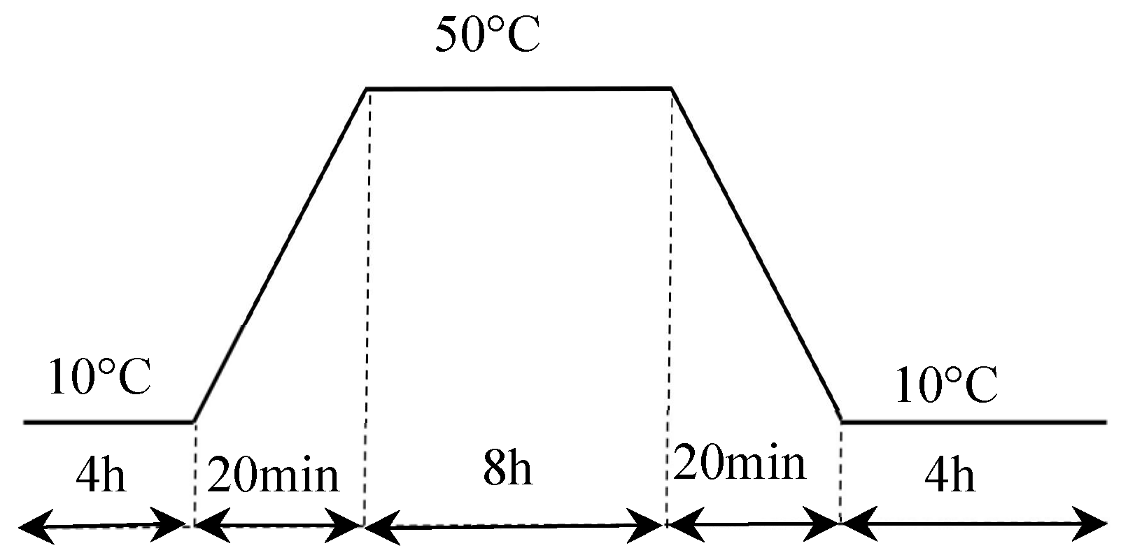
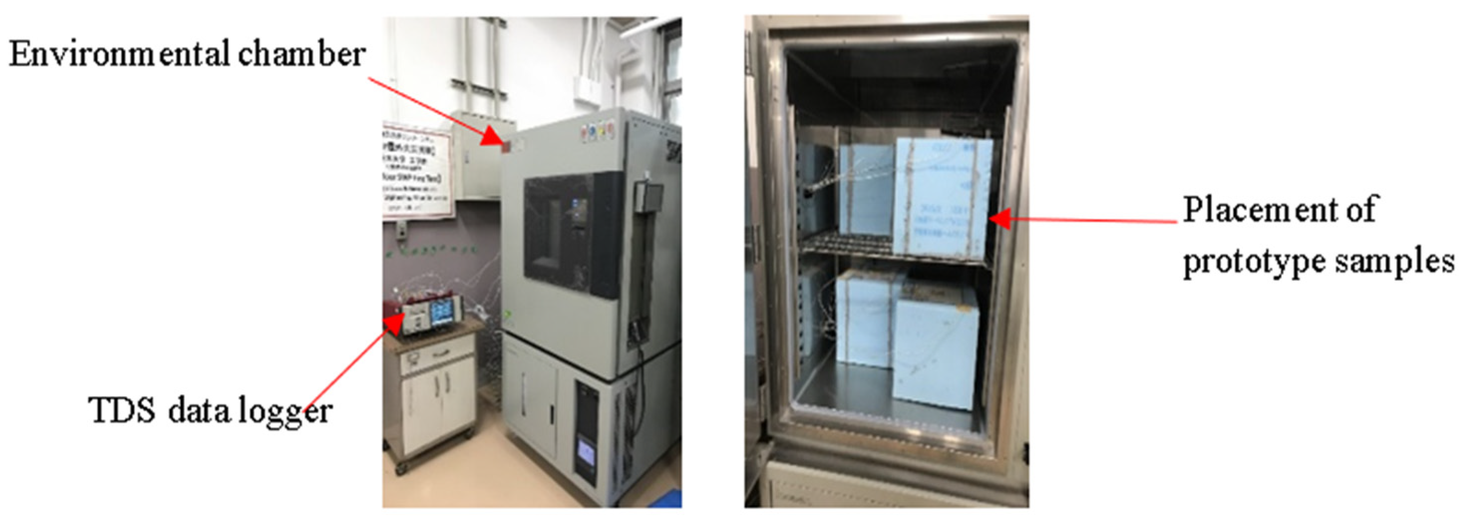
2.6. Experimental Program for Heat Cycle Test

The heat cycling procedure, outlined in Figure 1, encompassed a 21 h cycle. The chamber temperature during each cycle remained at 10 °C for a 4 h period, achieved at a gradual rate of 2.5 °C per minute. Subsequently, the temperature was increased from 10 °C to 50 °C in 20 min, and the temperature was maintained at 50 °C for 8 h before falling back to 10 °C in 20 min and being sustained at that level for 8 h.

2.7. Procedure for Preparing the Heat Cycle Test

The thermal cycling experiment was conducted using a specialized chamber (model ETAC dc-450 manufactured by Kodama Co., Ltd., in Tokyo, Japan) with adjustable temperature and humidity settings, as depicted in Figure 2.
To evaluate the impact of PCM foam concrete when employed in materials of building walls, enclosed prototype samples were constructed on a laboratory scale. The initial prototype was structured according to the following sequence, from the interior to the exterior: A PCM foam concrete layer with a 20 mm thickness was prepared for 200 mm × 200 mm × 20 mm specimens, accompanied by a 50 mm-thick layer of extruded polystyrene foam with 300 mm × 300 mm × 50 mm dimensions. The physical model’s configuration and a cross-sectional view of the prototype are visually presented in Figure 3. Within the prototype setup, a total of three thermocouples were employed. One thermocouple was positioned on the backside of the sample, another was placed on the surface, and a third was inserted into the middle of the prototype box. The mid-specimen thermocouples were utilized to facilitate comparisons with the various sides of the thermocouples.

3. Experimental Results and Discussion

3.1. Compressive Strength Test
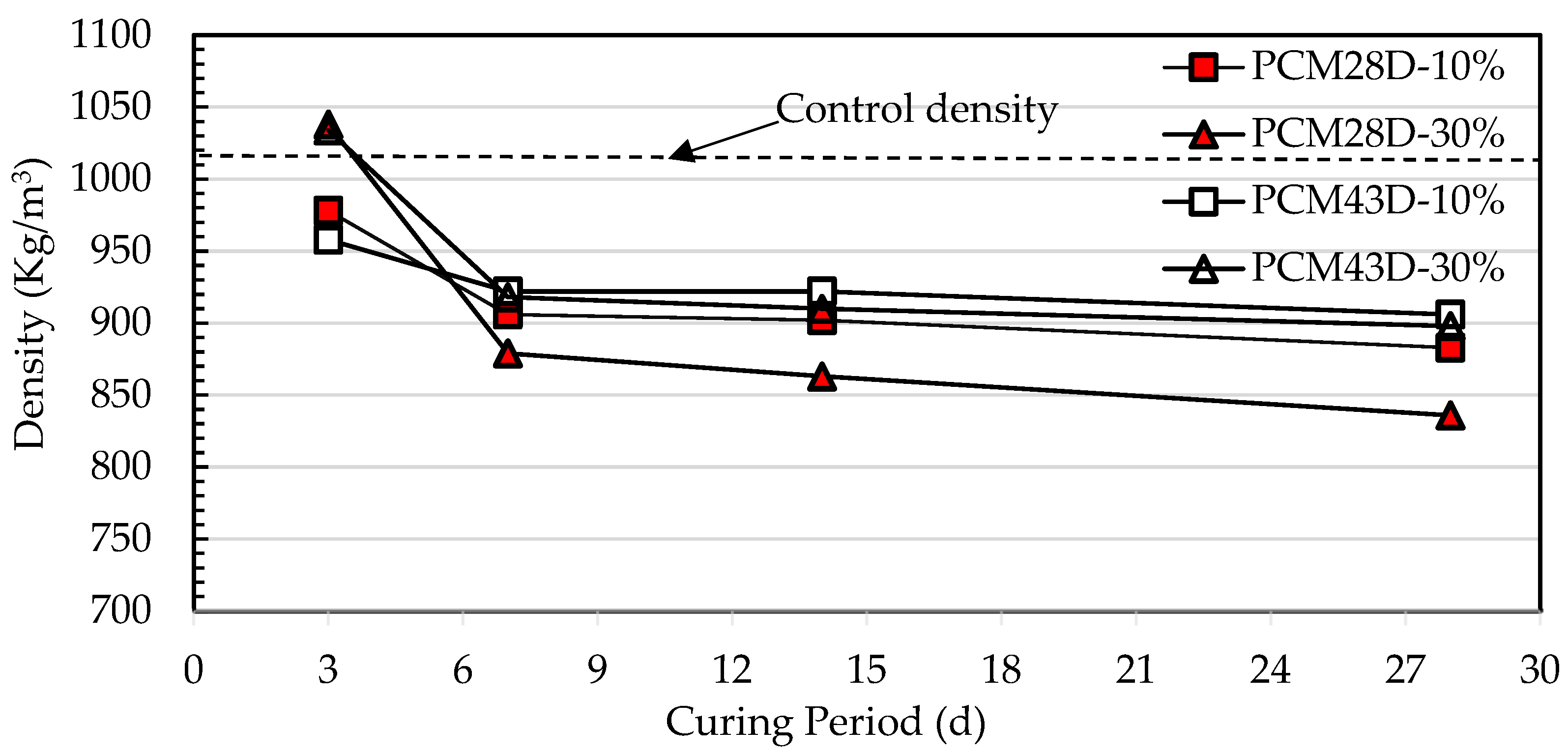
In Figure 4, the compressive strength that the No-PCM foam concrete displayed was compared with that of two concrete types containing PCMs (PCM28D and PCM43D). In both cases, 10% and 30% of the cement’s weight in foam concrete were substituted with PCMs. The tests were carried out at 7 and 28 days of curing, with a temperature of 40 °C and a relative humidity of 90%. On day 7, the compressive strength of No-PCM was recorded as 9.35 MPa. In contrast, the compressive strengths of PCM28D-10% and PCM43D-10% were 6.9 MPa and 6.8 MPa, with the strength decreasing by 26.2% and 27.2%, respectively. On day 28, a dramatic change was noted. The compressive strength of the No-PCM concrete was recorded as 13 MPa. In contrast, the compressive strengths of PCM28D-30% and PCM43D-30% were 4.8 MPa and 5.2 MPa, with the strength decreasing by 63% and 60%, respectively, compared with No-PCM. On the other hand, from day 7 to day 28, the compressive strengths of all samples increased to 28% for No-PCM; to 23.3% for PCM28D-10%; to 25.2% for PCM43D-10%; to 33.3% for PCM28D-30%; and to 19.2% for PCM43D-30%.
Two main factors in the reduction in the compressive strength are as follows: First, the results show that the increase in the PCM added to the PCM foam concrete causes a higher foam volume. A larger amount of foam creates higher porosity, leading to a reduction in the compressive strength exhibited by the PCM foam concrete. Furthermore, an increasing amount of PCM results in a notable decline in the compressive strength of the PCM foam concrete because of the low mechanical properties of the PCM. PCMs behave more like voids rather than aggregates and can be readily fractured under a compressive force. According to [32], the retardation of the hydration process is evident in cement mortars with PCMs; it was also reported that PCMs interacting with the C-S-H formation adversely impacts the strength [33,34,35].

3.2. Density Tests

The primary characteristics that define foam concrete density are stability and consistency. The outcomes of the density tests are provided in Table 5. Stability, in the context of foamed concrete, refers to the ratio of the initial (fresh) density to the final (hardened) density. Conversely, consistency relates to the ratio between the fresh density and the target density, which is determined by the quantity of foam introduced into the foam concrete mixture. In general, the density of foam concrete is influenced by both stability and consistency factors, both of which have a direct impact on the material’s strength. The test results demonstrate that all mix compositions containing PCM exhibited comparable levels of consistency and stability, closely aligning with the intended target densities.
The density test results of the PCM28D and PCM43D concrete with 10% and 30% PCM on days 3, 7, 14 and 28 are shown in Figure 5. For all types of PCM foam concrete, the control wet density was 1100 kg/m3. It is apparent that the density range of the PCM28D and PCM43D foam concrete was between 1050 and 836 kg/m3, with the highest recorded at 1050 kg/m3 for PCM43D-10% and the lowest at 836 kg/m3 for PCM28D-30%. A decrease in density was observed from days 3 to 28, and the calculated percentage variations were as follows: for PCM28D-10%, 9.7%; for PCM28D-30%, 16.8%; for PCM43D-10%, 5.4%; and for PCM43D-30%, 13.15%. The findings indicate that, with an increase in the quantity of PCM, the density of the foamed concrete decreases. This is attributed to the lower specific gravity of the PCMs in comparison to other components in foamed concrete [25].

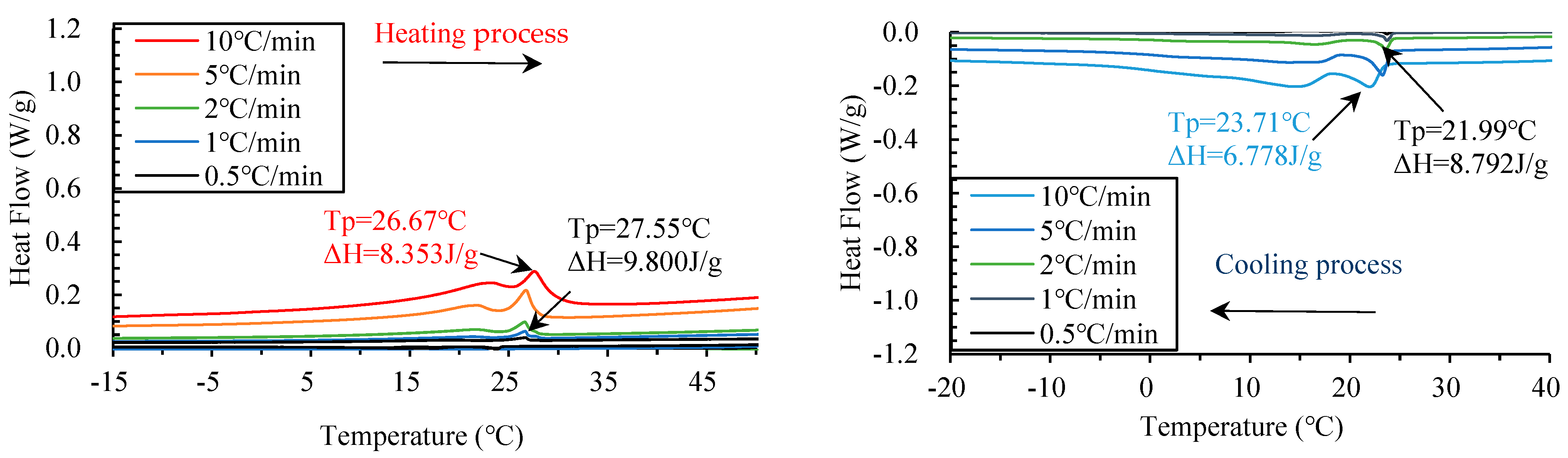
3.3. DSC Test and Thermal Analysis

The DSC test was conducted on PCM foam concretes (PCM28D and PCM43D) with a different amount of PCM using five distinct heating/cooling ranges between 0.5 °C/min and 10 °C/min. The DSC test was also conducted on both the No-PCM foam concrete and concrete with different amounts of PCM to determine their latent heat capacity.
Figure 6 and Figure 7 comprise line graphs that show the effects of all five heating/cooling rates of foam concrete with PCM28D (10% and 30%). A closer look at the scanning rates of the PCM28D foam concrete (Figure 6) reveals that the lowest latent heat (Δh) was PCM28D-10% at 0.5 °C/min, with melting and freezing peaks recorded at 27.55 °C and 21.99 °C, and their latent heat storage (Δh) was 9.80 J/g and 8.79 J/g, respectively. In contrast, the highest latent heat (Δh) was PCM28D-30% under 10 °C/min heating and cooling rates (Figure 7). The melting peak and the freezing peak were observed at 28.89 °C and 23.65 °C, and the latent heat storage capacity was 38.68 J/g and 32.68 J/g, respectively.
Regarding the PCM43D foam concrete, the heating/cooling cycle test results (10% and 30% samples) are shown in Figure 8 and Figure 9. By looking more closely at their scanning rates, it can be seen that the lowest latent heat (Δh) was for PCM43D-10% (Figure 8) when measured at a 0.5 °C/min heating and cooling rate. The melting peak was 43.53 °C with a latent heat storage capacity (Δh) of 12.48 J/g, and the freezing peak was 39.07 °C with a latent heat storage capacity of 14.47 J/g. Also, the latent heat (Δh) of PCM43D-30% was the highest (Figure 9) at a 10 °C/min heating and cooling rate. The melting peak was 45.32 °C with a latent heat storage capacity (Δh) of 42.87 J/g, and the freezing peak was 37.89 °C with a latent heat storage capacity of 41.01 J/g.
In conclusion, the DSC analysis conducted in this study had several significant findings. First, this DSC analysis showed an overall increase in the latent heat, depending on the added amount of PCM. Second, the impact of the heating and cooling rates on the behavior of PCMs was evident. As the heating rates increased, the freezing ranges became broader, and the maximum peaks shifted toward lower temperatures. There are two peaks that were noticed in the cooling rates in the results of both types of PCM foam concrete, regardless of the amount of PCM. It could be suggested that the two peaks have different reasons. The smaller peak could have been caused by a transition in the polymer shell of the PCM material itself, whereas the larger peak might have been caused by the phase change of the paraffin material. If so, this is in line with [36]. Third, a comparative analysis between two distinct PCM foam concretes (PCM28D and PCM43D) exhibited slight variations in their latent heat capacities. Specifically, the latent heat capacity of the melting and freezing peaks for PCM28D-30% exhibited lower latent capacities (38.68 J/g and 32.68 J/g) compared to PCM43D-30% (42.87 J/g and 41.01 J/g) at a scanning rate of 10 °C/min. This discrepancy can be attributed to the inherently lower latent heat capacity of pure PCM28D in comparison to PCM43D, the data of which were provided by the manufacturer. These findings underscore the importance of considering both the amount of PCM used and the heating rate when designing materials for thermal energy storage applications.

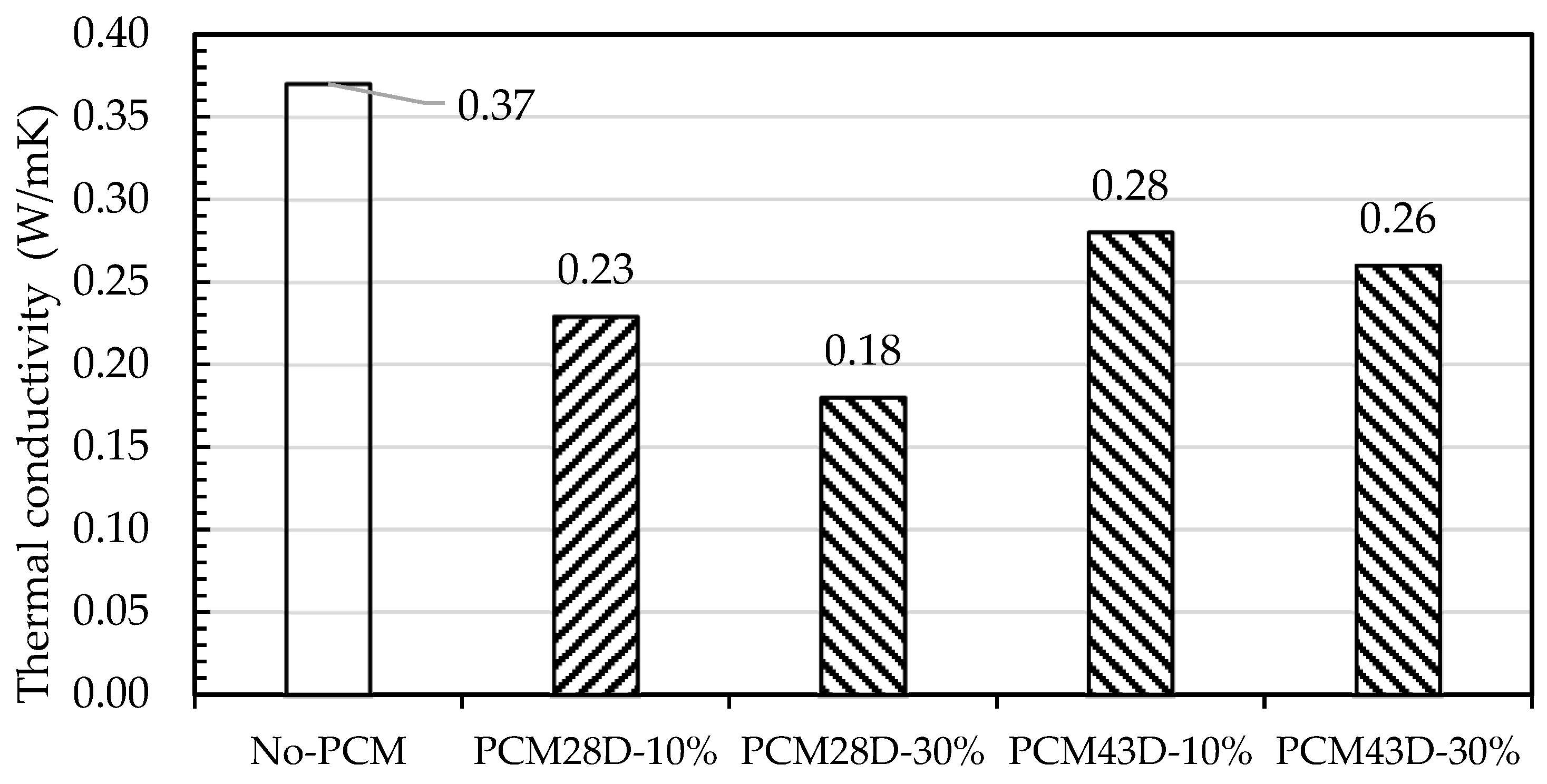
3.4. Thermal Conductivity

The impact of PCM substitution into foam concrete samples was measured on day 28 of the thermal conductivity test. For each designated mix, ranging from PCM28D-10% to PCM43D-30%, the thermal conductivity was measured (Figure 10). The thermal conductivity of PCM28D decreased to 37.8% and 51.3% when PCM replacements of 10% and 30% were introduced. For PCM43D, thermal conductivity reductions were found at 24.3% and 29.7%, respectively. The decline in thermal conductivity as the amount of PCM composite increased can be attributed to the lower thermal conductivity of the PCM28D and PCM43D composites, which falls within the range of 0.18–0.37 W/mK.
Earlier investigations have observed that the density of concrete has a significant impact on its thermal conductivity. This is in line with suggestions from [37], which concluded that thermal conductivity increases with higher densities due to the lower porosity of the sample. The density of both PCMs is lower than that of the No-PCM sample due to the increase in the PCM replacement, which could have resulted in the low thermal conductivity of PCM particles [38]. Another possible reason could be that the independent cell foam prevents pores from releasing heat, resulting in lower conductivity values [7,17,39].

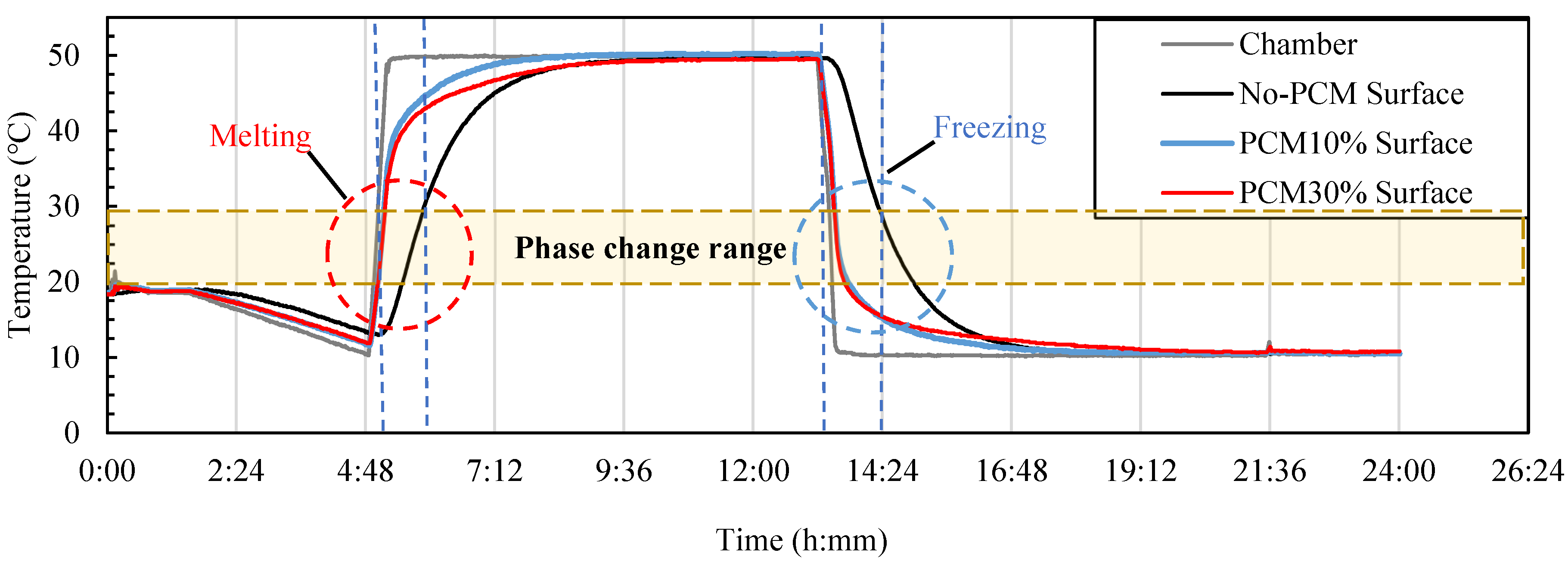
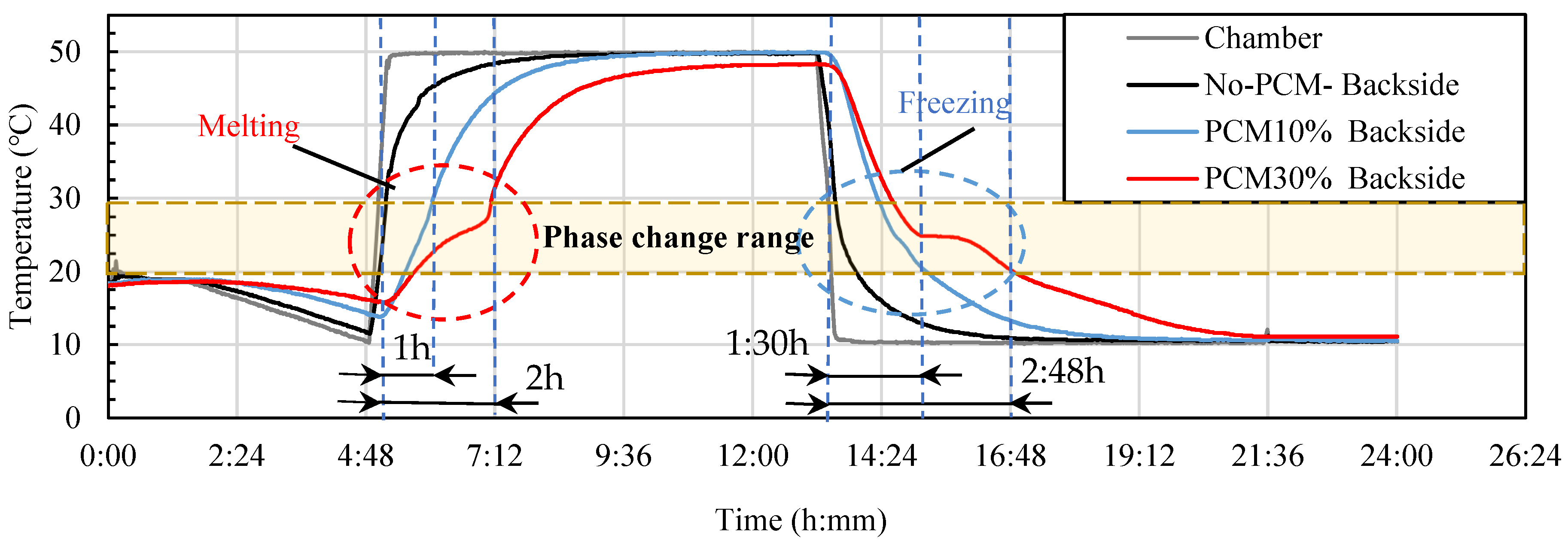
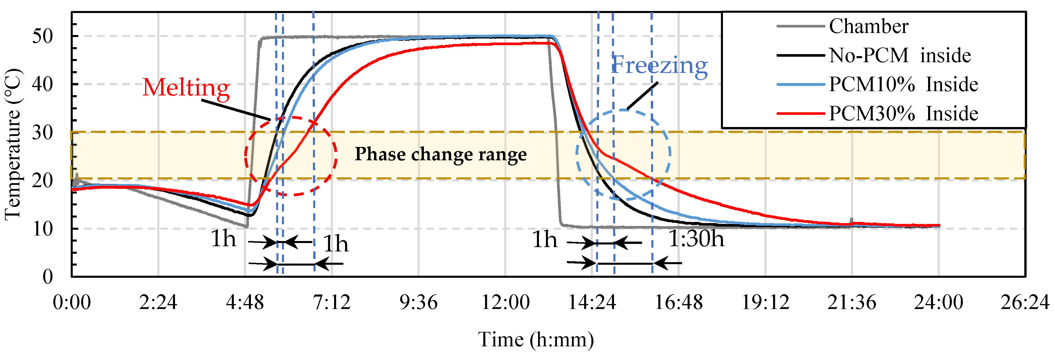
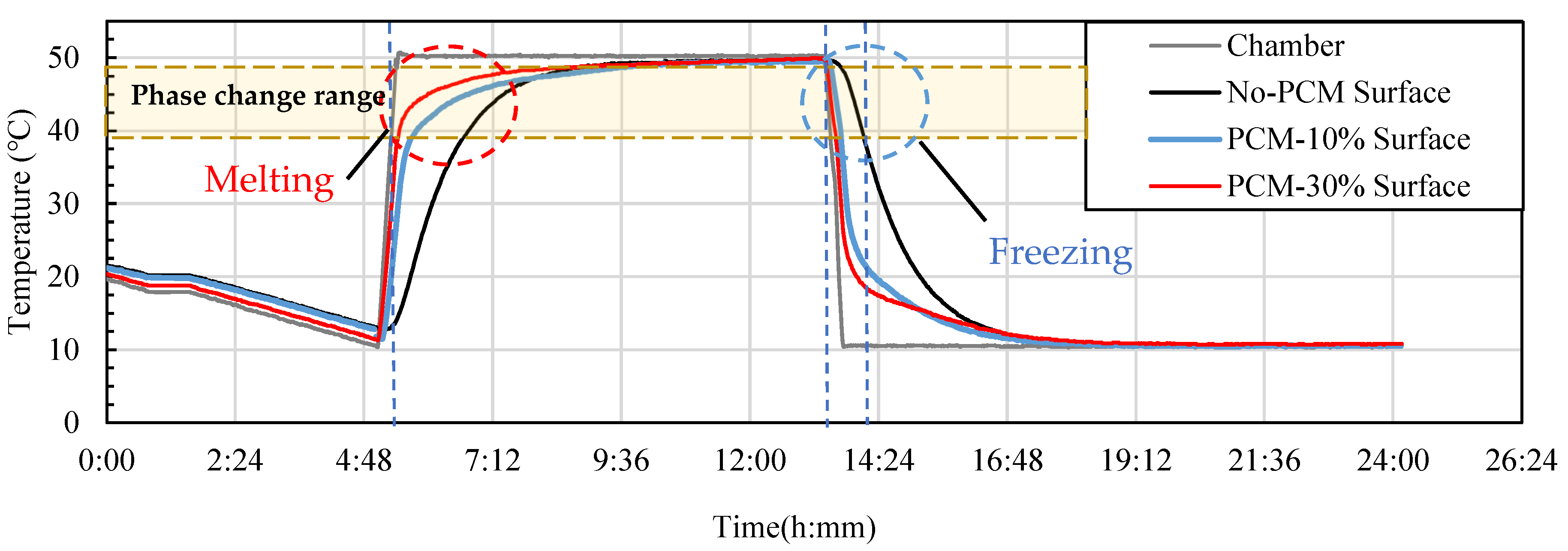
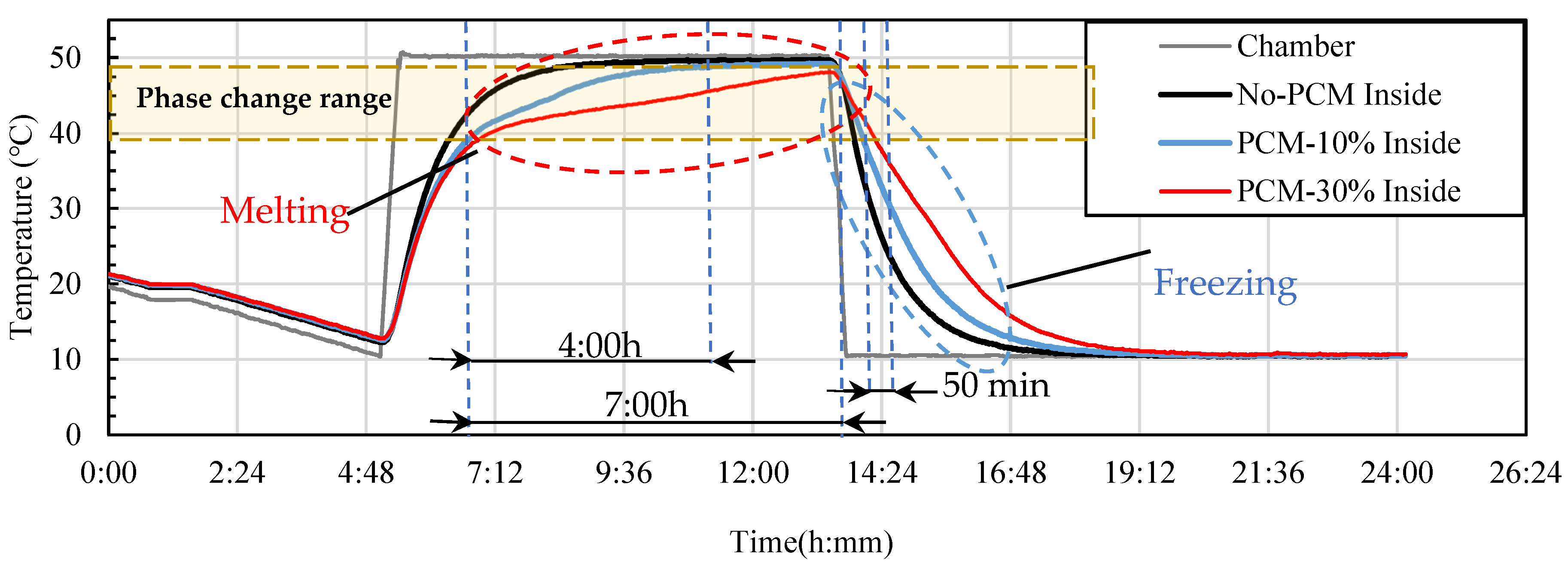
3.5. Thermocycle Analysis

The evaluation of the thermal properties of PCM foam concrete panels (PCM28D and PCM43D) with different proportions of PCMs was conducted through an analysis of temperature variations. The temperature was measured at multiple points, includingthe surface the backside of the foam concrete and the center of the prototype box. The heat cycling conditions included 24 h per cycle in total, with heating and cooling rates lasting for 8 h at 2.5 °C/min. The heat cycle temperature ranged between 10 °C and 50 °C. This condition was chosen based on the melting and freezing ranges of these two types of PCMs.
PCM28D has melting and freezing temperatures ranging between 20 °C and 30 °C. The temperature on the surface (Figure 11) of PCM28D-10% increased dramatically up to 40 °C at the beginning of the heating process and then gradually increased up to 50 °C in approximately 3 h, whereas the growth rate of the temperature of the No-PCM foam concrete was steady up to 50 °C. Moreover, on the backside of the foam concrete panel (Figure 12), the PCM in the foam concrete melts first, absorbs the heat and maintains the temperature for approximately one hour in a temperature range of 20–30 °C. After that, the temperature of PCM28D-10% gradually increased up to 50 °C, and No-PCM experienced a dramatic increase. On the inside of the prototype (Figure 13), the temperature trend almost identical tothat observedfor the No-PCM foam concrete occurred during the heating process. Contrarily, when the cooling process began, the surface temperature dropped dramatically from 50 °C to 20 °C. In the following 3 h, the temperature gradually decreased to 10 °C. On the backside of the foam concrete panel, initially, the PCM foam concrete froze and began releasing heat when the temperature was between 30 °C and 20 °C. Here, the temperature decreases observed in both PCM28D-10% and No-PCM had a similar trend despite the temperature delay of around 1 h 30 min in PCM28D-10%. On the inside of the prototype, there was almost no observed difference between the PCM28D-10% and No-PCM foam concrete during the cooling process.
Regarding PCM28D-30%, the temperature on the surface (Figure 11) of PCM28D-30% increased dramatically up to 40 °C at the beginning of the heating process. After that, the temperature gradually increased up to 50 °C in approximately 3 h, whereas the growth rate in the temperature of the No-PCM foam concrete was steady up to 50 °C. Moreover, on the backside of the foam concrete panel, with temperature increases from 20 °C to 30 °C, the PCM in the foam concrete began to melt and absorb heat. The melting curve is shown in Figure 12. The temperature was delayed for around 2 h compared to No-PCM, which experienced a dramatic increase. After completing the melting process, the temperature gradually increased up to 47 °C in approximately 7 h. Moreover, on the inside of the prototype (Figure 13), as the temperature increased from 20 °C to 30 °C, the PCM in the foam concrete began to melt and absorb heat, and the room temperature was maintained for around 60 min. After finishing the melting process, the temperature gradually increased to 50 °C in approximately 3 h. Contrarily, when the cooling process commenced, the surface temperature fell dramatically from 50 °C to 20 °C. In approximately the 3 h that followed, the temperature gradually decreased to 10 °C. On the backside of the foam concrete panel, as the temperature fell from 30 °C to 20 °C, the PCM foam concrete began freezing and released heat. The temperature was delayed for approximately 2 h 48 min, and that of No-PCM dramatically decreased. On the inside of the prototype, the temperature difference between No-PCM and PCM28D-30% can be clearly seen. The room temperature was maintained for around 1 h 30 min during the cooling process compared to No-PCM.
Regarding the PCM43D foam concrete samples, the results of the cooling and heating cycles with different proportions are illustrated in Figure 14, Figure 15 and Figure 16. For PCM43D-10%, it had the lowest heat, and the melting and freezing range was between 40 °C and 50 °C. On the surface (Figure 14), the temperature escalated dramatically up to 40 °C at the beginning of the heating process, and then it gradually increased up to 50 °C in approximately 3 h. That of No-PCM remained steady up to 50 °C. Simultaneously, heat was transferred to the backside of the foam concrete panel (Figure 15). As the temperature increased from 40 °C to 50 °C, the PCM in the foam concrete began to melt and absorb heat. The temperature was delayed for approximately 6 h. However, compared with No-PCM, the temperature dramatically increased. On the inside of the prototype (Figure 16), the room temperature was maintained for 4 h within the specified range. No-PCM’s temperature showed the highest indoor temperature values throughout the heating process. In contrast, when the cooling process commenced, the surface temperature dropped dramatically from 50 °C to 40 °C. In approximately the 3 h that followed, the temperature gradually decreased to 10 °C, and the rate of the decrease in the temperature of No-PCM foam concrete remained steady up to 10 °C. On the backside of the foam concrete panel, as the temperature fell from 50 °C to 40 °C, the PCM foam concrete began freezing and released heat. The temperature was maintained for approximately 30 min within the phase change range. After that, the temperature gradually decreased and reached 10 °C after around 4 h, and that of No-PCM dramatically decreased. On the inside of the prototype, the observed temperature decreased; both PCM43D-10% and No-PCM followed a similar trend.
For PCM43D-30%, the surface temperature increased gradually and reached 50 °C after 4 h (Figure 14), and on the backside of the foam concrete panel (Figure 15), as the temperature rose from 40 °C to 50 °C, the PCM in the foam concrete melted and began absorbing heat. There was a temperature delay of approximately 8 h, and the temperature curve became nearly flat compared with No-PCM, the temperature of which dramatically increased. Moreover, on the inside of the prototype (Figure 16), the room temperature was maintained for around 7 h within the phase change range, and that of No-PCM gradually increased up to 50 °C. In contrast, when the cooling process began, the surface temperature dropped dramatically from 50 °C to 20 °C. In approximately the 3 h that followed, the temperature gradually decreased to 10 °C, and the rate of the decrease in the temperature of the No-PCM foam concrete remained steady up to 10 °C. On the backside of the foam concrete panel, as the temperature fell from 47 °C to 40 °C, the PCM foam concrete began freezing and releasing heat. The temperature was maintained for approximately 50 min within the phase change temperature range. An interesting fact is that the DSC analysis revealed two cooling peak points, occurring at 40 °C and 30 °C. The heat cyclic test showed similar patterns with those two peaks shown at 40 °C and 30 °C during the cooling process of the heat cycle test. The temperature of No-PCM consistently had the lowest values during the cooling process. Moreover, on the inside of the prototype, the temperature was maintained for around 50 min during the cooling phase. After that, the temperature decreased steadily until the end of the temperature range, and the temperature of No-PCM decreased gradually. As can be seen from Figure 14, Figure 15 and Figure 16, the temperatures observed on the surface of the foam concrete panel over time were different from those on the backside of the foam concrete. This difference could be explained by the absorption of heat from the surface and its release from the backside of the foam concrete to the inside of the prototype.
In conclusion, both types of PCMs in foam concrete were effective in maintaining temperature within the phase change range. Consequently, PCM foam concrete can find versatile practical applications within buildings, including lightweight blocks and precast panels. The enhanced thermal performance offered by PCM-infused foam concrete can be applied across real-world construction projects to improve energy efficiency, comfort levels and overall sustainability. Given the scope of this research to determine the energy-saving potential of microencapsulated PCMs (PCM28D and 43D), it became clear that, when the amount of PCM in the foam concrete increased, the room temperature was maintained for a longer period. Regarding the inside of the prototype, it was revealed that both PCMs in foam concrete were effective in maintaining the temperature within the phase change range. However, on the surface of the prototypes, the temperature of both types of PCMs increased dramatically, although it was expected that the excessive temperature would be reduced. Some differences were observed between PCM28D and PCM43D, which is another significant finding of this experiment. PCM28D showed a lower energy-saving potential compared to that of PCM43D. This can be explained by their thermal properties. For example, PCM28D-30% had latent heat of 38.68 J/g, which was less than that of PCM43D-30% (42.87 J/g). Additionally, it also had lower thermal conductivity (0.18 W/mK) compared to that of PCM43D-30% (0.28 W/mK). This is because PCM28D had lower latent heat and thermal conductivity, which resulted in PCM28D not showing a proper thermal performance. In other words, PCM28D could not efficiently transfer heat through the inside of the concrete panel due to its low thermal conductivity [40]. Therefore, it could be argued that PCM43D has greater potential in decreasing energy consumption because of its capacity to restrict temperature variations and to shift heating or cooling loads [41]. This suggests that PCMs with higher temperature ranges between 40 °C and 50 °C could be suitable for regions with hot climates to minimize heat transfer from the exteriors to the interiors of buildings.

4. Conclusions

This study provides the material properties and thermal performance of foamed concrete incorporating PCMs, emphasizing the contributions of PCMs to the mixture. The results of the series of tests conducted, as part of this experiment, are as follows:
  • Mechanical testing revealed that both PCM28D-30% and PCM-43D-30% exhibit sufficient mechanical properties for various applications, including ALC panels with a required compressive strength of 3 MPa.
  • Regarding the DSC test results, the energy storage capability of PCM foam concrete increases with a higher PCM content.
  • The thermal conductivity results showed a decrease in thermal conductivity with increasing amounts of PCM composites.
  • The thermocycle analysis demonstrated a favorable performance for the PCM foam concrete types, maintaining temperatures within the desired ranges for extended periods.
In conclusion, PCM foam concrete demonstrates beneficial characteristics, including improved thermal performance and latent heat storage capabilities. The findings of this study indicate that the incorporation of PCMs’ high melting and freezing ranges in foam concrete can effectively reduce indoor temperature fluctuations, leading to enhanced energy saving and improved thermal comfort in buildings.
Moreover, there are a few considerations that should be addressed in the future. First, as a follow up to this small-scale test conducted on lightweight PCM foam concrete, more experimental studies are needed to ensure the proper application of PCM foam concrete in large-scale, real building environments. Second, what needs to be considered is the cost of PCMs, which would be a challenge for PCM applications. Therefore, further studies could also focus on ways to make PCM applications cost-effective and affordable.

Author Contributions

Conceptualization, P.-E.B.-E., E.K., M.L. and P.X.; Methodology, P.-E.B.-E., C.M. and P.X.; Investigation, P.-E.B.-E. and M.L.; Resources, P.-E.B.-E., M.L. and P.X.; Data curation, M.L. and P.X.; Writing—original draft, P.-E.B.-E.; Writing—review & editing, P.-E.B.-E., S.P. and E.K.; Visualization, P.-E.B.-E., S.P. and C.M.; Supervision, S.P., E.K. and C.M. All authors have read and agreed to the published version of the manuscript.

Funding

This research received no external funding.

Data Availability Statement

Data will be made available on request.

Conflicts of Interest

The authors declare no conflict of interest.

References

  1. IEA. Buildings. License: CC BY 4.0ings. IEA: Paris, France, 2022. Available online: https://www.iea.org/reports/buildings (accessed on 8 June 2023).
  2. World Energy Outlook. 2022. Available online: www.iea.org/t&c/ (accessed on 25 May 2023).
  3. Far, C.; Far, H. Improving energy efficiency of existing residential buildings using effective thermal retrofit of building envelope. Indoor Built. Environ. 2019, 28, 744–760. [Google Scholar] [CrossRef]
  4. Lotfabadi, P.; Hançer, P. A Comparative Study of Traditional and Contemporary Building Envelope Construction Techniques in Terms of Thermal Comfort and Energy Efficiency in Hot and Humid Climates. Sustainability 2019, 11, 3582. [Google Scholar] [CrossRef]
  5. Gan, V.J.L.; Lo, I.M.C.; Ma, J.; Tse, K.T.; Cheng, J.C.P.; Chan, C.M. Simulation optimisation towards energy efficient green buildings: Current status and future trends. J. Clean. Prod. 2020, 254, 120012. [Google Scholar] [CrossRef]
  6. Hawes, D.W.; Feldman, D.; Banu, D. Latent heat storage in building materials Objectives of research in thermal storage building materials. Energy Build. 1993, 20, 77–86. [Google Scholar] [CrossRef]
  7. Hekimoğlu, G.; Nas, M.; Ouikhalfan, M.; Sarı, A.; Kurbetci, Ş.; Tyagi, V.; Sharma, R.; Saleh, T.A. Thermal management performance and mechanical properties of a novel cementitious composite containing fly ash/lauric acid-myristic acid as form-stable phase change material. Constr. Build. Mater. 2021, 274, 122105. [Google Scholar] [CrossRef]
  8. Tyagi, V.V.; Kaushik, S.C.; Tyagi, S.K.; Akiyama, T. Development of phase change materials based microencapsulated technology for buildings: A review. Renew. Sustain. Energy Rev. 2011, 15, 1373–1391. [Google Scholar] [CrossRef]
  9. Zhao, L.; Wang, H.; Luo, J.; Liu, Y.; Song, G.; Tang, G. Fabrication and properties of microencapsulated n-octadecane with TiO2 shell as thermal energy storage materials. Sol. Energy 2016, 127, 28–35. [Google Scholar] [CrossRef]
  10. Giro-Paloma, J.; Martínez, M.; Cabeza, L.F.; Fernández, A.I. Types, methods, techniques, and applications for microencapsulated phase change materials (MPCM): A review. Renew. Sustain. Energy Rev. 2016, 53, 1059–1075. [Google Scholar] [CrossRef]
  11. Liu, F.; Wang, J.; Qian, X. Integrating phase change materials into concrete through microencapsulation using cenospheres. Cem. Concr. Compos. 2017, 80, 317–325. [Google Scholar] [CrossRef]
  12. Hunger, M.; Entrop, A.G.; Mandilaras, I.; Brouwers, H.J.H.; Founti, M. The behavior of self-compacting concrete containing micro-encapsulated Phase Change Materials. Cem. Concr. Compos. 2009, 31, 731–743. [Google Scholar] [CrossRef]
  13. Ahmad, M.R.; Chen, B.; Shah, S.F.A. Investigate the influence of expanded clay aggregate and silica fume on the properties of lightweight concrete. Constr. Build. Mater. 2019, 220, 253–266. [Google Scholar] [CrossRef]
  14. Gencel, O.; Nodehi, M.; Hekimoğlu, G.; Ustaoğlu, A.; Sarı, A.; Kaplan, G.; Bayraktar, O.Y.; Sutcu, M.; Ozbakkaloglu, T. Foam Concrete Produced with Recycled Concrete Powder and Phase Change Materials. Sustainability 2022, 14, 7458. [Google Scholar] [CrossRef]
  15. Gencel, O.; Bayraktar, O.Y.; Kaplan, G.; Arslan, O.; Nodehi, M.; Benli, A.; Gholampour, A.; Ozbakkaloglu, T. Lightweight foam concrete containing expanded perlite and glass sand: Physico-mechanical, durability, and insulation properties. Constr. Build. Mater. 2022, 320, 126187. [Google Scholar] [CrossRef]
  16. Khan, Q.S.; Sheikh, M.N.; McCarthy, T.J.; Robati, M.; Allen, M. Experimental investigation on foam concrete without and with recycled glass powder: A sustainable solution for future construction. Constr. Build. Mater. 2019, 201, 369–379. [Google Scholar] [CrossRef]
  17. Gencel, O.; Nodehi, M.; Bayraktar, O.Y.; Kaplan, G.; Benli, A.; Gholampour, A.; Ozbakkaloglu, T. Basalt fiber-reinforced foam concrete containing silica fume: An experimental study. Constr. Build. Mater. 2022, 326, 126861. [Google Scholar] [CrossRef]
  18. Bat-Erdene, P.E.; Pareek, S. Experimental Study on the Development of Fly Ash Foam Concrete Containing Phase Change Materials (PCMs). Materials 2022, 15, 8428. [Google Scholar] [CrossRef]
  19. Frigione, M.; Lettieri, M.; Sarcinella, A. Phase Change Materials for Energy Efficiency in Buildings and Their Use in Mortars. Materials 2019, 12, 1260. [Google Scholar] [CrossRef]
  20. Alawadhi, E.M. Thermal analysis of a building brick containing phase change material. Energy Build. 2008, 40, 351–357. [Google Scholar] [CrossRef]
  21. Hasan, M.I.; Basher, H.O.; Shdhan, A.O. Experimental investigation of phase change materials for insulation of residential buildings. Sustain. Cities Soc. 2018, 36, 42–58. [Google Scholar] [CrossRef]
  22. Microtek. Available online: https://www.microteklabs.com/ (accessed on 18 September 2023).
  23. JIS A 6201; Japanese Industrial Standard of Fly Ash. Japanese Standard Association: Tokyo, Japan, 1991.
  24. JIS A 1108; Compressive Strength Test Methods for Concrete. Japanese Standard Association: Tokyo, Japan, 2018.
  25. Kheradmand, M. Incorporation of hybrid phase change materials in plastering mortars for increased energy efficiency in buildings. Ph.D. Thesis, Universidade do Minho, Braga, Portugal, 2016. [Google Scholar] [CrossRef]
  26. Andrássy, Z.; Szánthó, Z. Thermal behaviour of materials in interrupted phase change. J. Therm. Anal. Calorim. 2019, 138, 3915–3924. [Google Scholar] [CrossRef]
  27. He, B.; Martin, V.; Setterwall, F. Phase transition temperature ranges and storage density of paraffin wax phase change materials. Energy 2004, 29, 1785–1804. [Google Scholar] [CrossRef]
  28. Fatahi, H.; Claverie, J.; Poncet, S. Thermal Characterization of Phase Change Materials by Differential Scanning Calorimetry: A Review. Appl. Sci. 2022, 12, 12019. [Google Scholar] [CrossRef]
  29. JIS H 8453; Measurement Method for Thermal Conductivity of Thermal Barrier Coating. Japanese Standard Association: Tokyo, Japan, 2018.
  30. Baccilieri, F.; Bornino, R.; Fotia, A.; Marino, C.; Nucara, A.; Pietrafesa, M. Experimental measurements of the thermal conductivity of insulant elements made of natural materials: Preliminary results. Int. J. Heat. Technol. 2016, 34, S413–S419. [Google Scholar] [CrossRef]
  31. Dakhli, Z.; Chaffar, K.; Lafhaj, Z. The Effect of Phase Change Materials on the Physical, Thermal and Mechanical Properties of Cement. Science 2019, 1, 27. [Google Scholar] [CrossRef]
  32. Eddhahak, A.; Drissi, S.; Colin, J.; Caré, S.; Neji, J. Effect of phase change materials on the hydration reaction and kinetic of PCM-mortars. J. Therm. Anal. Calorim. 2014, 117, 537–545. [Google Scholar] [CrossRef]
  33. Kheradmand, M.; Azenha, M.; De Aguiar, J.L.B.; Krakowiak, K.J. Thermal behavior of cement based plastering mortar containing hybrid microencapsulated phase change materials. Energy Build. 2014, 84, 526–536. [Google Scholar] [CrossRef]
  34. Chen, X.; Wei, S.; Wang, Q.; Tang, M.; Shen, X.; Zou, X.; Shen, Y.; Ma, B. Morphology prediction of portlandite: Atomistic simulations and experimental research. Appl. Surf. Sci. 2020, 502, 144296. [Google Scholar] [CrossRef]
  35. Xian, G.; Liu, Z.; Wang, Z.; Zhou, X. Study on the Performance and Mechanisms of High-Performance Foamed Concrete. Materials 2022, 15, 7894. [Google Scholar] [CrossRef]
  36. Eddhahak-Ouni, A.; Colin, J.; Drissi, S.; Neji, J. Analysis by Differential Scanning Calorimetry of concrete modified with microencapsulated phase change materials. In Proceedings of the 2013 International Renewable and Sustainable Energy Conference (IRSEC), Ouarzazate, Morocco, 7–9 March 2013. [Google Scholar]
  37. Huang, X.; Zhu, C.; Lin, Y.; Fang, G. Thermal properties and applications of microencapsulated PCM for thermal energy storage: A review. Appl. Therm. Eng. 2018, 147, 841–855. [Google Scholar] [CrossRef]
  38. Meshgin, P.; Xi, Y. Multi-scale composite models for the effective thermal conductivity of PCM-concrete. Constr. Build. Mater. 2013, 48, 371–378. [Google Scholar] [CrossRef]
  39. Qiao, L.; Li, N.; Luo, L.; He, J.; Lin, Y.; Li, J.; Yu, L.; Guo, C.; Murto, P.; Xu, X. Design of monolithic closed-cell polymer foamsviacontrolled gas-foaming for high-performance solar-driven interfacial evaporation. J. Mater. Chem. A Mater. 2021, 9, 9692–9705. [Google Scholar] [CrossRef]
  40. Wi, S.; Yang, S.; Park, J.H.; Chang, S.J.; Kim, S. Climatic cycling assessment of red clay/perlite and vermiculite composite PCM for improving thermal inertia in buildings. Build. Environ. 2020, 167, 106464. [Google Scholar] [CrossRef]
  41. Cui, H.; Tang, W.; Qin, Q.; Xing, F.; Liao, W.; Wen, H. Development of structural-functional integrated energy storage concrete with innovative macro-encapsulated PCM by hollow steel ball. Appl. Energy 2017, 185, 107–118. [Google Scholar] [CrossRef]
Figure 1. Heat cycling program.
Buildings 13 02481 g001
Figure 2. Environmental chamber for heat cycle test.
Buildings 13 02481 g002
Figure 3. Prototype sample for heat cycle test.
Buildings 13 02481 g003
Figure 4. Impact of PCM addition on compressive strength of foam concrete.
Buildings 13 02481 g004
Figure 5. Effect of adding PCM on density of foam concrete.
Buildings 13 02481 g005
Figure 6. DSC measurement results: PCM28D-10% at different heating and cooling rates.
Buildings 13 02481 g006
Figure 7. DSC measurement results: PCM28D-30% at different heating and cooling rates.
Buildings 13 02481 g007
Figure 8. DSC measurement results: PCM43D-10% at different heating and cooling rates.
Buildings 13 02481 g008
Figure 9. DSC measurement results: PCM43D-30% at different heating and cooling rates.
Buildings 13 02481 g009
Figure 10. Results of the thermal conductivity test for foam concrete with and without PCM.
Buildings 13 02481 g010
Figure 11. Heat cycle analysis of different amounts of PCM28D on the surface.
Buildings 13 02481 g011
Figure 12. Heat cycle analysis of different amounts of PCM28D on the backside of the surface.
Buildings 13 02481 g012
Figure 13. Heat cycle analysis of different amounts of PCM28D on the inside of the prototype.
Buildings 13 02481 g013
Figure 14. Heat cycle analysis of different amounts of PCM43D on the surface.
Buildings 13 02481 g014
Figure 15. Heat cycle analysis of different amounts of PCM43D on the backside of the surface.
Buildings 13 02481 g015
Figure 16. Heat cycle analysis of different amounts of PCM43D on the inside of the prototype.
Buildings 13 02481 g016
Table 1. Thermo-physical properties of various microencapsulated PCMs.
MaterialNatureSize (μm)Melting (°C)Heat of Fusion (J/g)Solid Content %
PCM28DDry15.0–30.026 to 3018997.0–100.0
PCM43DDry15.0–30.041 to 4523597.0–100.0
Table 2. Chemical composition of rapid hardening cement.
SO3ClNa2OeqMgOC3SC2SC3AC4AFIg.Loss
RHC2.990.0070.441.186412881.05
Table 3. Chemical composition of fly ash.
SIO2Al2O3Fe2O3CaOMgOGlassp (g/cm3)Ig.Loss
Japan FA-II (JIS)64.523.94.85.31.577.13.142.10
Table 4. Mix compositions for PCM foam concrete.
Mix
Designation
Cement
(kg)
Fly Ash
(kg)
(10%)
W/C
(Lit)
0.3
PCM
(kg)
10–30%
SP
(kg)
1%
Foam
(g)
Reference (0%)4.500.451.3500.045310
PCM 28D (10%)3.150.450.940.450.045440
PCM 28D (30%)2.250.450.671.350.045890
PCM 43D (10%)3.150.450.940.450.045430
PCM 43D (30%)2.250.450.671.350.045900
Table 5. Density test results of foam concrete containing PCMs.
(Density Control)
Mix
Designation
(wt.%)Curing
Condition
Curing Period
(d)
Fresh
Density (kg/m3)
Dry Density
(kg/m3)
Consistency
(%)
Stability
(%)
No-PCM040 °C RH-95%3104410211.01.0
7104410161.01.0
14104410121.01.0
28104410081.01.0
PCM28D-10%1040 °C RH-95%39379780.91.0
79379060.91.0
149379020.91.0
289378830.91.1
PCM28D-30%3040 °C RH-95%3102010381.01.0
710208791.01.2
1410208631.01.2
2810208361.01.2
PCM43D-10%1040 °C RH-95%39199580.91.0
79199220.91.0
149199220.91.0
289199060.91.0
PCM43D-30%3040 °C RH-95%3105010341.11.0
710509181.11.1
1410509100.00.0
2810508980.00.0
Disclaimer/Publisher’s Note: The statements, opinions and data contained in all publications are solely those of the individual author(s) and contributor(s) and not of MDPI and/or the editor(s). MDPI and/or the editor(s) disclaim responsibility for any injury to people or property resulting from any ideas, methods, instructions or products referred to in the content.

