Article

Research on the Dynamic Response of a Slope Reinforced by a Pile-Anchor Structure under Seismic Loading

1
Faculty of Urban Construction, Beijing University of Technology, Beijing 100124, China
2
Xinjiang Key Laboratory of Geohazard Prevention, Xinjiang Institute of Engineering, Urumqi 830023, China
*
Author to whom correspondence should be addressed.
Buildings 2023, 13(10), 2500; https://doi.org/10.3390/buildings13102500
Submission received: 12 August 2023 / Revised: 25 September 2023 / Accepted: 27 September 2023 / Published: 1 October 2023
(This article belongs to the Section Building Structures)

Abstract

:
In earthquake-prone areas, pile-anchor structures are widely employed for slope reinforcement due to their reliable performance. Current research has primarily focused on static and quasi-static analyses of slopes reinforced by using pile-anchor structures, with limited investigation into their dynamic response. In this work, the finite element method (FEM) is used to study the dynamic behavior of a pile-anchor slope system, and the extended finite element method (XFEM) is used to simulate the progressive failure processes of piles. Three different reinforcement schemes, which include no support, pile support, and pile-anchor support, are considered to examine the performance of the pile-anchor structure. The simulation results suggest that the pile-anchor structure displays a reduction of 39.6% and 40.6% in the maximum shear force and bending moment of the piles, respectively, compared to the pile structure. The XFEM is utilized to model the progressive failure process of the piles subjected to seismic loading. We find that crack initiation in the pile body near the slip surface, for both the pile supported and the pile-anchor supported conditions, occurs when the peak ground acceleration arrives. Crack growth in the piles completes in a very short period, with two distinct increments of crack area observed. The first increment occurs when the peak ground acceleration arrives and is significantly larger than the second increment. Consequently, for the seismic design of piles, it is necessary to strengthen the pile body around slip surfaces. The novelty of this paper is that we realize the simulation of crack initiation and propagation in piles subjected to seismic loading.

1. Introduction

Pile-anchor structures have been widely used for stabilizing slopes in earthquake-prone areas [1,2,3]. Engineering practice finds that piles could fail due to incorrect design, especially under earthquakes; such failures often initiate from localized damage caused by stress concentration [4]. For example, pile damage and anchor head failure were observed after the Wenchuan earthquake [5]. Current research on pile-anchor systems has primarily focused on static and quasi-static analyses. Understanding how these systems respond under seismic loading should be further investigated for the seismic design of slopes [6].
Research methods on the response of slope reinforcement mainly involve physical model tests and numerical simulations. Shaking table tests provide a powerful tool for modeling the dynamic characteristics of reinforced slopes. For instance, Huang et al. [7] studied the seismic response of a slope reinforced by a pile-anchor structure based on 50 g dynamic centrifuge tests, and they found that the pile bore most of the soil pressure, while the anchor assisted in preventing the pile from outward tilting. Hu et al. [8] demonstrated the effective performance of a pile-anchor structure for stabilizing slopes even if under intense earthquakes. Xu et al. [9] performed a shaking table model test on a rock slope anchored with adaptive anchor cables, and they demonstrated that the adaptive anchor cables could buffer the seismic loading through energy dissipation sliding sleeves. Qu et al. [10] proposed an analytical model for analyzing the dynamic behaviors of reinforced slopes and performed a shaking table test to verify the model. Jahromi et al. [11] conducted an experimental study of the deformation of piles in a sandy slope using a 1 g shaking table test, and they found that the dynamic response of the slope gradually decreased from slope toe to crest. Cheng et al. [12] reported a model test on the response of anchors subjected to cyclic loading. Srilatha et al. [13] and Panah and Eftekhari [14] studied the influence of peak acceleration and frequency on the dynamic behavior of reinforced slopes through shaking table tests. Although shaking table tests can provide insights into the failure mechanism of slopes under seismic conditions, their applicability is limited by the model size. Moreover, these tests are costly and time-consuming.
Numerical simulations offer an economical and reliable approach for analyzing the behaviors of reinforced slopes [15,16,17], including the finite element method (FEM), the finite difference method (FDM), mesh-free methods [18,19,20,21,22], and artificial intelligence methods [23,24,25,26,27,28,29,30,31,32]. Among these methods, the FEM and the FDM are the most widely used. For instance, Cai and Ugai [33] investigated the influence of piles on the stability of a slope using the shear strength reduction FEM, and they concluded that the pile row performed best in stabilizing slopes when it was placed in the middle of the slope. Won et al. [34] reported a stability analysis of a pile-slope system using the explicit finite difference code FLAC 3D. Lin et al. [35] employed FLAC3D to simulate the seismic response of slopes reinforced with anchored frame beams and pile-slab wall. Joorabchi et al. [36] presented an approach for calculating yield acceleration and displacement of a drilled shaft-reinforced slope using the FEM method. Huang et al. [1] conducted a comparative analysis of slope stability under earthquake conditions using different support schemes (i.e., no support, pile support, anchor support, and pile-anchor support) through the FEM method, and they found that the pile-anchor structure performed best in stabilizing slopes. Xu et al. [6] utilized the FEM to investigate the influence of base excavation, continuous rainfall, and earthquakes on slope stability, and they evaluated the effectiveness of pile-anchor structures in slope reinforcement. Ye et al. [37] modeled the dynamic response of a slope reinforced by frame and anchors using the FEM. Based on a limit analysis, Yan et al. [38] presented a numerical method for slope stability analysis which considered axial force change under seismic loading. Chakraborty and Dey [39] reported a probabilistic assessment of the dynamic behavior of a toe-excavated hillslope. These previous studies have provided insights into the dynamic responses of reinforced slopes under seismic shaking, including the internal force of piles and anchors and deformation of slopes, which is helpful for the seismic design of slopes. However, most numerical simulations have failed to consider the pile–soil interaction, and have yet elucidated the damage and failure mechanism of supporting structures under earthquakes. In addition, most studies have focused on the force characteristics of piles [40,41,42], but little is known about their progressive failure process involving crack initiation and propagation.
In this work, an investigation is conducted on the dynamic response of a reinforcement-slope system under seismic loading. Here, three scenarios are considering, including no support, pile support, and pile-anchor support. By analyzing parameters such as slope deformation, axial force of anchors, and shear force and bending moment of piles, this research aims to reveal the dynamic response of the reinforcement. In addition, simulation of the progressive failure process of the piles is realized using the extended finite element method, which provides insight into the failure mechanism of the piles. The findings of this study could provide helpful guidance for the seismic design of slopes.

2. Numerical Model

2.1. Methodology

In this work, the finite element software ABAQUS was used to simulate the dynamic response of a pile-anchor reinforced slope. A FEM dynamic analysis was used to simulate the wave propagations in the slope. Dynamic/implicit in ABAQUS was adopted as the solver to carry out the analysis. The equation governing the dynamic analysis is represented as follows [43]:
[ M ] { u ¨ } + [ C ] { u ˙ } + [ K ] { u } = { F }
where [M] is the mass matrix, [C] is the damping matrix, [K] is the stiffness matrix, F is the external force, and u is the nodal point displacement.

2.2. Model Description

For this study, we selected the simplified three-dimensional slope model proposed by Cai and Ugai [33] (Figure 1), which is widely employed for numerical analyses and validations [33,34,44,45]. In the model, two cylindrical concrete piles, each with a length of 15.5 m, are placed at the midpoint of the slope. The diameter of each pile (D) is 0.8 m. According to Won et al. [34], the spacing S between the pile centers is 2.4 m, which is three times the pile diameter (S = 3D). Two anchors, each with a free section of 12 m and an anchoring section of 8 m, are placed in the slope with an inclination angle of 15° to the horizontal line. The anchor head is located 0.5 m below the top of the pile. Tie constraints in the ABAQUS software are used to define the connection between the anchor and the pile, so that the anchor head and the pile have the same degree of freedom at the tied nodes. The parameter settings in the model are listed in Table 1, which are based on previous studies [33,46,47]. In the simulations, the piles and anchors were modeled as linear elastic materials, while the soil was modeled by the Mohr–Coulomb failure criterion. Three monitoring points, namely A1, A2, and A3, were set in the model to measure the acceleration and displacement of the slope under seismic loading (Figure 1).
In the FEM model, the piles and anchors are regarded as linear elastic materials. The soil and piles are modeled by the C3D8R solid element which is an 8-node linear brick. The anchors are represented using the T3D2 truss element which is a 2-node linear displacement element that can transmit only axial force and use linear interpolation for position and displacement. To capture the interaction between the piles and soil, a master-slave contact algorithm was implemented. Specifically, the surface of the piles is designated as the master surface, while the soil acts as the slave surface. The normal contact is set as hard contacts, allowing for separation between the soil and piles when tension occurs. The tangential direction of the contacts incorporates a penalty function that follows the Coulomb’s friction law. Thus, when the shear stress on the contact surface exceeds the frictional strength, relative sliding between the soil and piles occurs [48]. The friction coefficient is assumed to be 0.3. A binding constraint is applied between the anchors and piles, while an embedded region is utilized to model the interface between the anchors and soil. The prestress of the anchors is achieved using the cooling method. When the slope is not reinforced, the safety factor is calculated, while the safety factor results of the shear strength finite element method, the finite difference code FLAC, and Bishop’s simplified method are 1.14, 1.15, and 1.13, respectively [33]. This validated the method used in this work to some extent.

2.3. Seismic Input

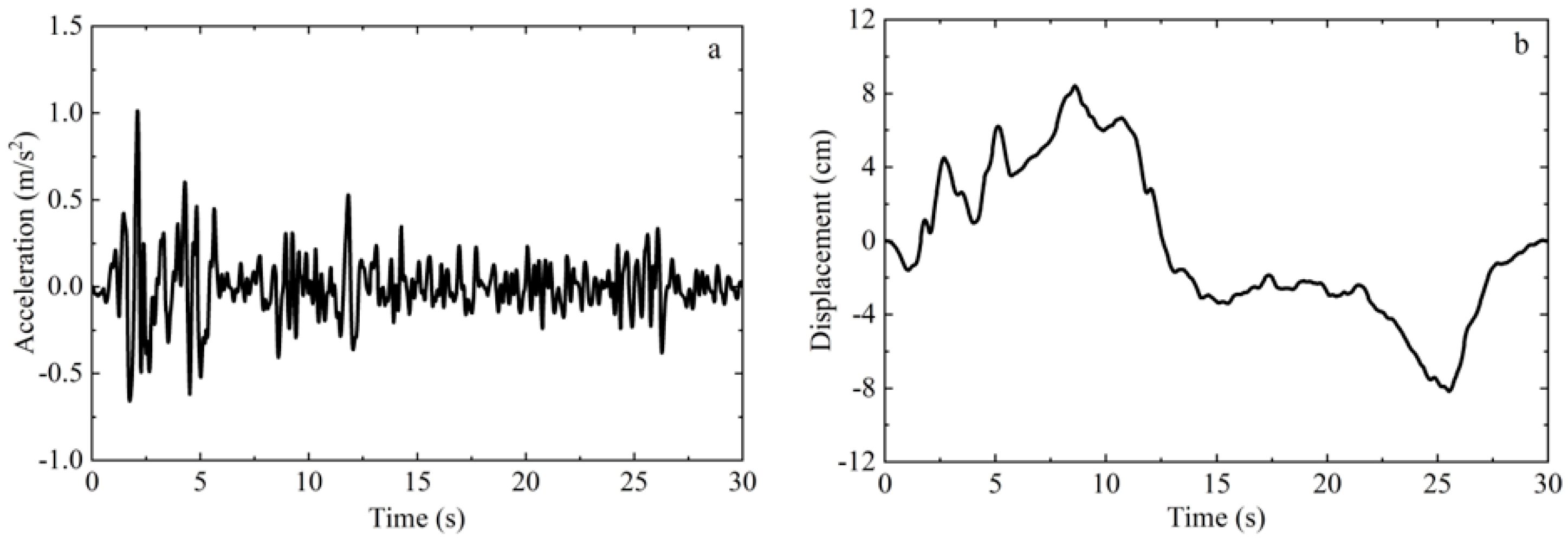
Horizontal seismic shaking is a major factor that contributes to slope failures [49]. In this study, to simulate the dynamic response characteristics of the reinforced slope under seismic loading, a horizontal seismic wave was applied in the X-direction at the base of the model. The selected seismic wave was based on the horizontal acceleration time history of the El Centro wave. In order to eliminate baseline drift, baseline correction was performed on the seismic wave [50,51]. The adjusted seismic wave had a duration of 30 s, a time step of 0.02 s, and a peak acceleration of approximately 0.1 g. The time histories of acceleration and displacement are shown in Figure 2.

2.4. Material Damping

The Rayleigh damping model, which has been widely used to incorporate damping in dynamic response analyses, was selected. In the model, the damping matrix [C] is a linear combination of the mass matrix [M] and the stiffness matrix [K] [30,52]:
[ C ] = α [ M ] + β [ K ]
where α and β are the damping coefficients calculated by:
α = ξ 2 ω i ω j ω i + ω j
β = 2 ξ ω i + ω j
where ωi and ωj refer to the characteristic frequencies corresponding to the ith and jth modes of the structural model, respectively, and ξ is the damping ratio which is set as 0.05 in this research.

2.5. Boundary Conditions

To account for the impact of the initial stress state of the slope on its dynamic response, a finite element analysis method incorporating static and dynamic coupling was employed for the boundary condition [53,54,55]. The numerical computation process consisted of three steps:
(1)
The bottom of the model is fixed, while the lateral boundaries are subjected to normal constraints. This allows for stress equilibrium within the model. Then, the entire model is subjected to gravity to simulate the self-weight load. As a result, nodal reactions at the left and right lateral boundaries can be obtained, providing valuable insights into the distribution of forces within the slope under gravity.
(2)
To achieve the conversion from static to dynamic boundary conditions, the horizontal constraints of the left and right boundaries of the model are released; meanwhile, the displacement in the vertical direction is restricted. Additionally, the reaction forces obtained from Step 1 are applied to the corresponding nodes at the left and right boundaries to maintain balance. This approach allows for a smooth transition from the static calculation to the dynamic analysis, ensuring consistency in the boundary conditions and enabling an accurate assessment of the dynamic response of the reinforced slope under seismic loading.
(3)
In the dynamic analysis, the horizontal constraint on the bottom of the model is released. Simultaneously, ground motion is applied in the horizontal direction. This setup allows for the investigation of the dynamic response characteristics of the reinforced slope under seismic loading.

2.6. Validation

(1)
Stability of the slope without reinforcement under gravity
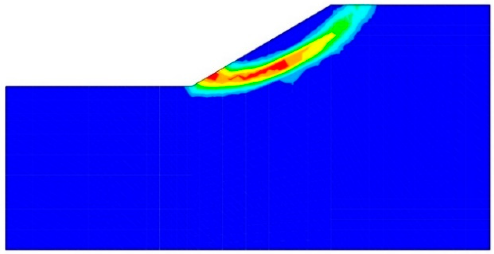
The strength reduction method is employed to calculate the safety factor (FOS) for the unsupported slope under gravity. The safety factor is calculated to be 1.15 in this research. When the slope has no reinforcement, the safety factors calculated by Cai and Ugai [33], the FLAC, and Bishop’s simplified method are 1.14, 1.15, and 1.13, respectively [34]. Figure 3 shows the critical slip surface within the slope.
(2)
Dynamic response of the slope without reinforcement under seismic loading
The acceleration time-history curves of the three monitoring points in the slope with no support under seismic loading are shown in Figure 4. The dynamic response characteristics of these monitoring points display similarity to the input seismic wave (Figure 3). The peak accelerations of points A1, A2, and A3 are 1.62 m/s2, 1.80 m/s2, and 2.54 m/s2, respectively.

3. Dynamic Response of the Slope Model Reinforced by Different Structures

In the simulations, three different reinforcement schemes were considered, i.e., no support, pile support, and pile-anchor support. We compared the performances of different structures on the effectiveness of stabilizing the slope.

3.1. Dynamic Response of the Soil Slope

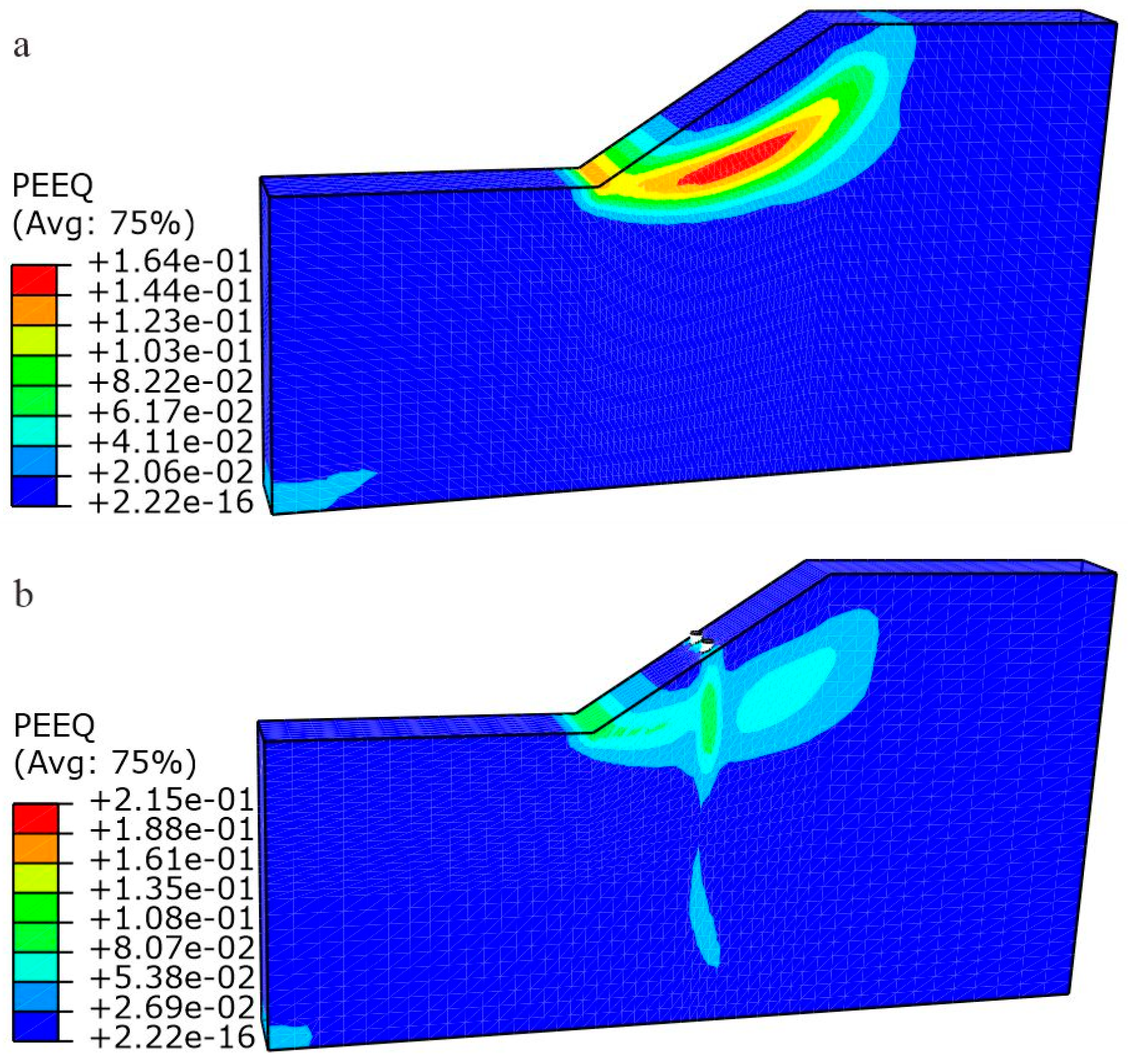
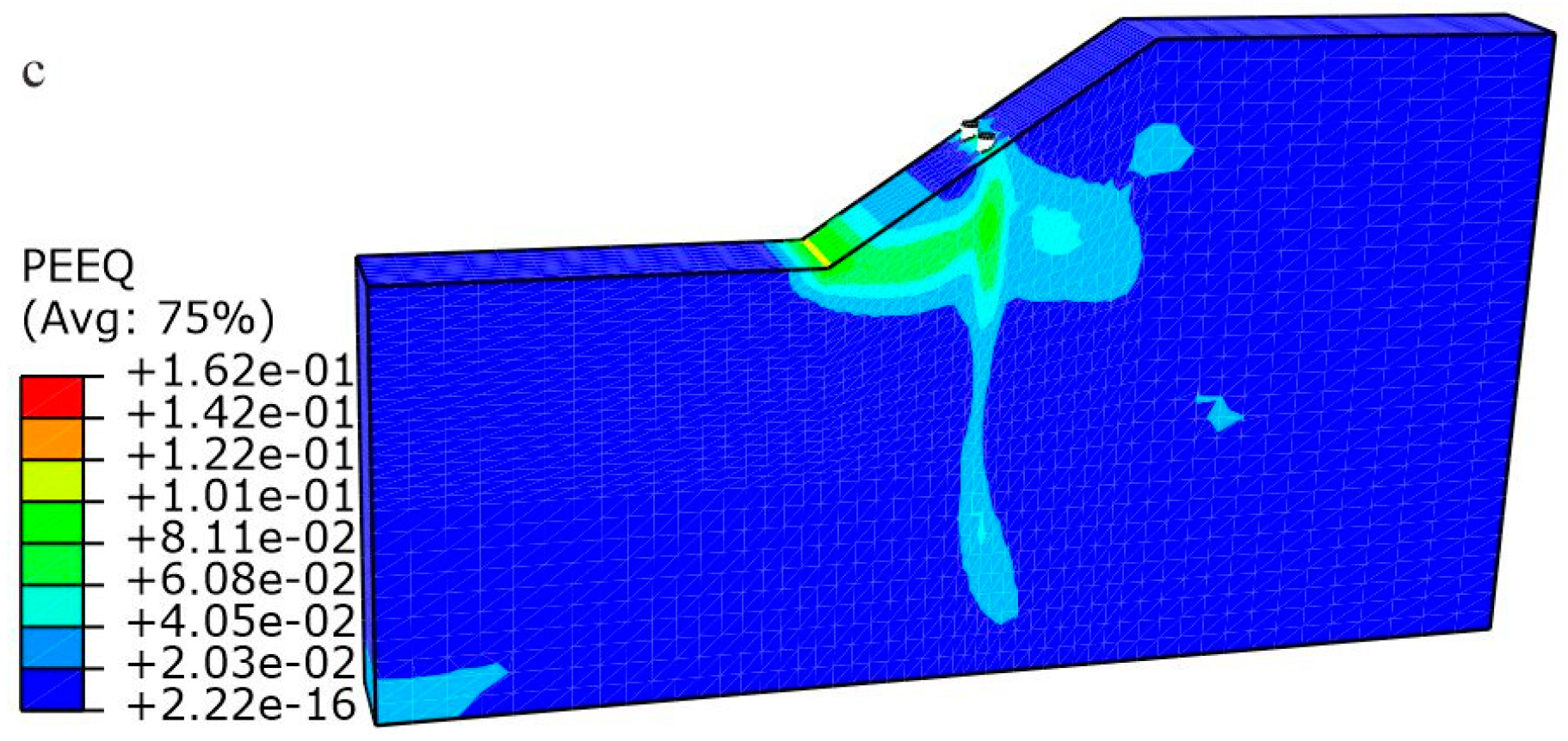
Equivalent plastic strain is a measure of cumulative plastic deformations during seismic loading processes, which provides a comprehensive representation of the cumulative effect of seismic loading [56]. Figure 5 illustrates the equivalent plastic strain cloud diagrams in the slope with different reinforcement schemes after seismic loading. It can be observed from Figure 5 that the unsupported slope experiences a through-going sliding surface extending from the slope toe to the slope crest. The plastic zone of the slope reinforced by piles is cut into two segments due to the influence of the piles (Figure 5b); and therefore, the overall failure of the slope is constrained. Notably, the pile-anchor structure further enhances the reinforcement area, and the plastic strain primarily occurs in the soil in front of the piles (Figure 5c).
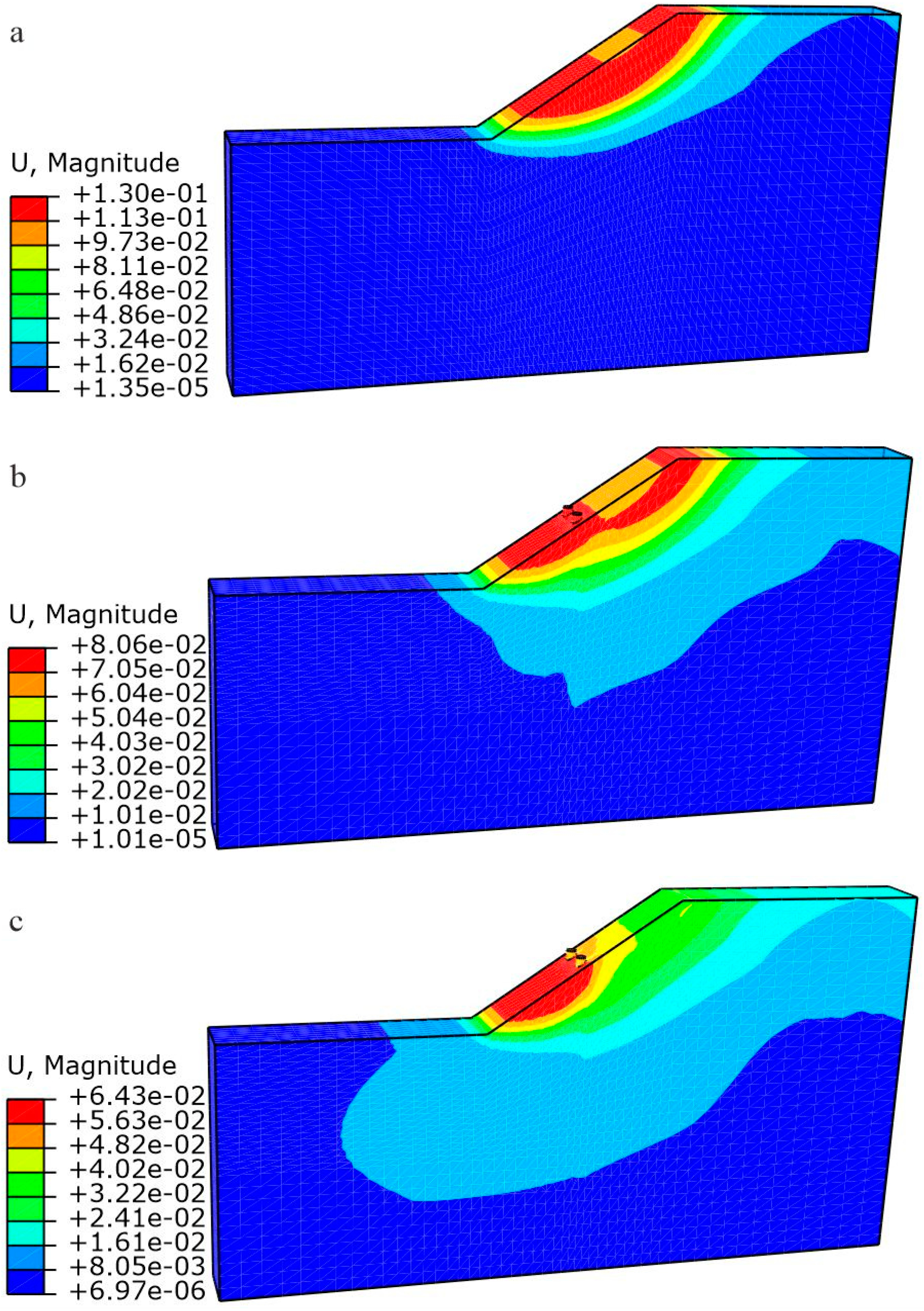
Figure 6 presents the displacement cloud diagrams of the slope with different reinforcement schemes after seismic loading. It is evident that the slope supported by the pile-anchor structure yields the smallest displacement compared with other reinforcement schemes. This observation suggests that the pile-anchor structure bonds the slope to form a cohesive unit, enabling coordinated displacement and deformation between the structure and the slope under seismic loading. The piles, which serve as the primary load-bearing components, effectively reduce slope deformation. It should be noted that the soil behind the piles is prone to suffering from overtop failure (Figure 6b), indicating that the pile-reinforced structure may not provide sufficient support for the slope. The combination of anchors and piles not only effectively restrains overall slope deformation but also enhances the stiffness of the soil behind the piles, contributing to reliable seismic performance.
Figure 7 shows the peak accelerations of the monitoring points in different reinforcement schemes. Under horizontal loading, the acceleration response of the slope exhibits a nonlinear elevation amplification effect. Figure 8 shows the horizontal displacement measured in the slope reinforced by the pile-anchor structure. The horizontal displacement of each monitoring point agrees well with the displacement of the input seismic wave. Significant deviations from the input baseline occur near the peak acceleration of the input seismic wave (Figure 2a), indicating that the deformation of the slope is mainly caused by the peak acceleration.

3.2. Dynamic Response of the Piles

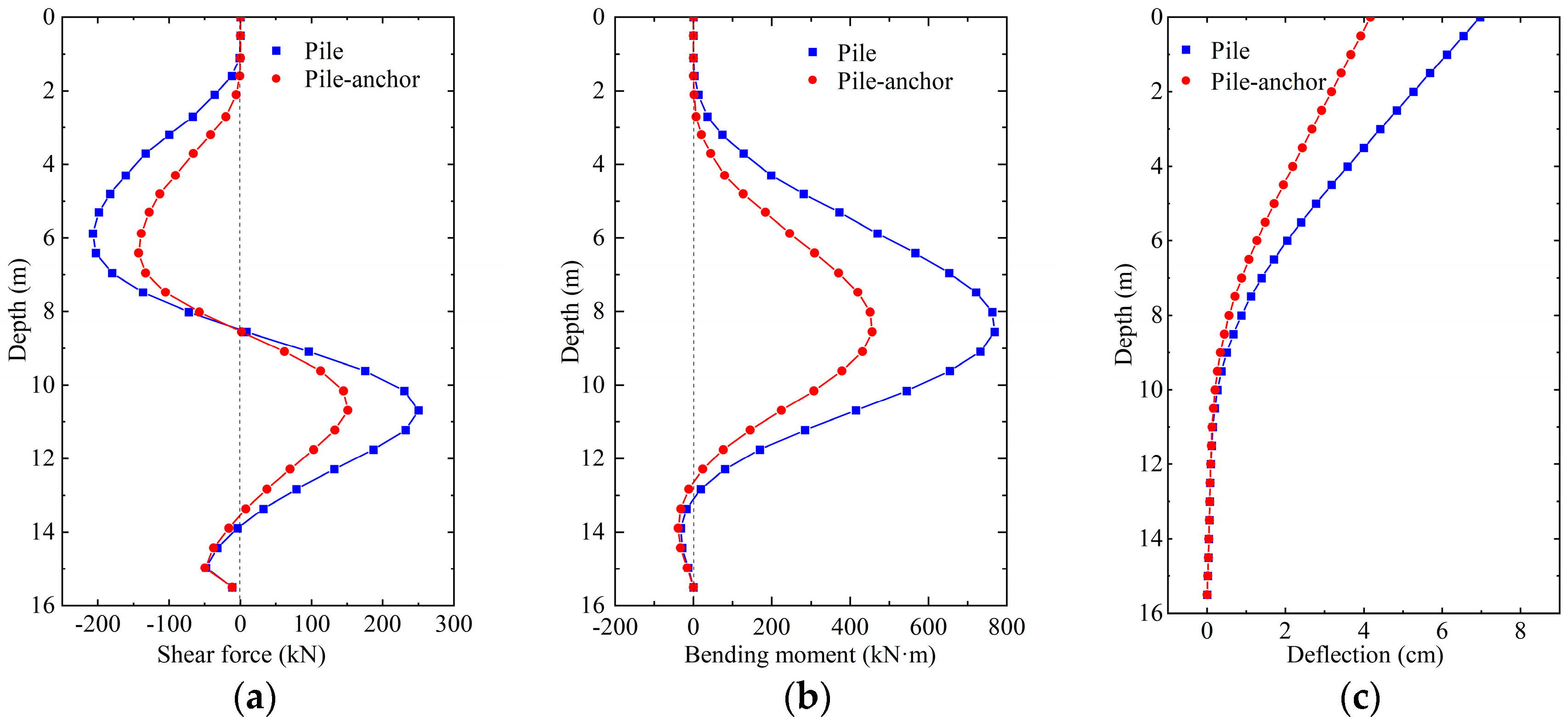
The post-processing visualization module ‘View Cut’ in the ABAQUS software is used to slice the piles to extract the section stress. The shear force is obtained by multiplying the section stress by the section area, while the bending moment is obtained by multiplying the section stress by the section moment of inertia. Figure 9 illustrates the distributions of the shear force, bending moment, and deflection along the pile for the pile-supported and pile-anchor-supported conditions after seismic loading. Here, the anchors in the pile-anchor-supported condition are not prestressed. For both conditions, the shear force reaches the first peak at a depth of approximately 6.0 m which is near the slip surface. The maximum bending moment occurs at a depth of 8.5 m and is located below the slip surface. The maximum deflections of the pile for the pile-supported and pile-anchor-supported conditions are 7.0 and 4.2 cm, respectively, demonstrating the effectiveness of the anchors in controlling pile deflection. When the slope is only supported by the piles, the maximum shear force and bending moment of the piles are 220 kN and 768 kN·m, respectively. However, for the pile-anchor-supported condition, these values decrease to 151 kN and 456 kN·m, representing reductions of 31.3% and 39.4%, respectively. These results highlight the effectiveness of the pile-anchor structure in improving the stress state of the piles and preventing bending damage caused by insufficient pile stiffness during earthquakes.

3.3. Dynamic Response of the Anchor

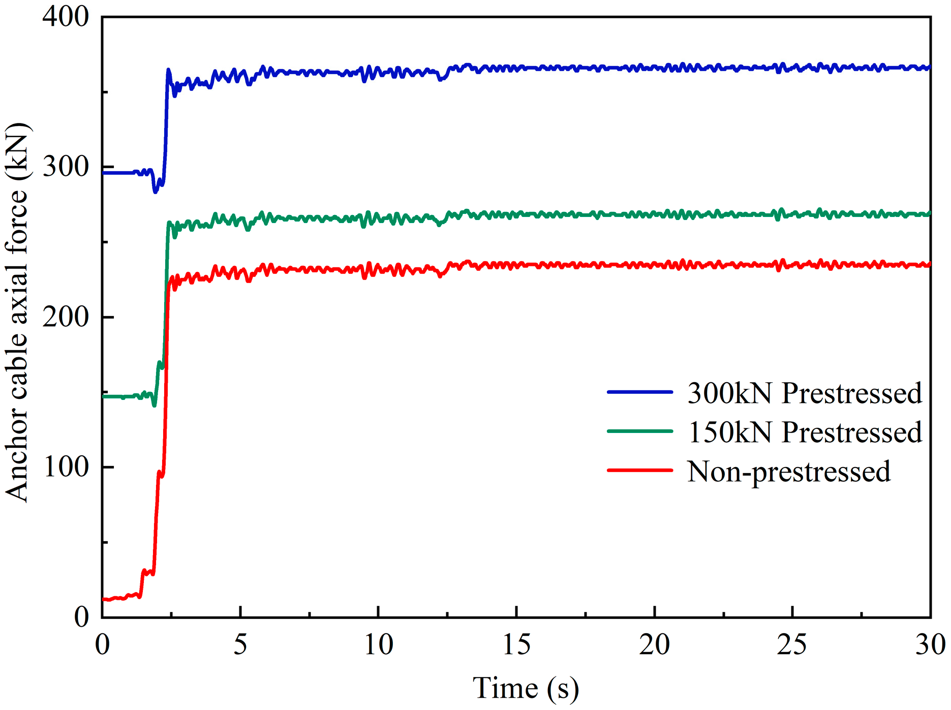
In this section, three cases for the anchors are set in the simulations, i.e., Case 1 with no prestress, Case 2 with prestress of 150 kN, and Case 3 with prestress of 300 kN. The time-history curves of the maximum axial force of the anchors with different prestresses are shown in Figure 10. Under seismic shaking, the anchors experienced rapid increments in the axial force at t = 2.5 s when the peak ground acceleration arrived, and then the axial force converged to a stable value. This suggests that the soil strongly pushed the pile to a tilt, leading to a rapid increase in the anchor tension but remaining within the elastic deformation range [57]. The anchor forces in Cases 1, 2, and 3 after seismic shaking are 236, 270, and 367 kN, respectively. The response of the anchor force is sensitive to the input seismic wave. The increment in the anchor force mainly occurs when there are significant changes in seismic acceleration amplitude, making the anchors susceptible to damage. Consequently, in the design of anchors, it is necessary to consider instantaneous increments in axial force caused by seismic loading in order to prevent the failure of the anchors.

4. Progressive Failure Process of the Piles Subjected to Seismic Loading

The failure of piles often starts from localized damage caused by stress concentration during earthquakes [11]. However, little research has been conducted on the progressive failure process of piles. To address this limitation, research on the failure characteristics of piles including crack initiation and propagation was conducted using the extended finite element method (XFEM). The XFEM, proposed by Belytschko and Black (1999) [58], is a widely used approach for modeling crack propagation. It incorporates extended functions into the displacement solution of finite elements to model cracks. In this research, the piles are represented as elastic materials and the damage of the piles follows the traction–separation laws. The failure process of piles can be investigated using an improved displacement approximation expression [58,59]:
u = I = 1 N N I ( x ) [ u I + H ( x ) a I + α = 1 4 F α ( x ) b I α ]
where NI(x) is the standard finite element shape function of node I, uI is the nodal displacement vector, H(x) is the Heaviside step function, Fα(x) is the elastic asymptotic crack-tip function, and aI and b I α are the degree of freedom vectors. The maximum principal stress criterion is adopted, which is described by:
f = { σ m a x σ m a x o }
where σ m a x o is the maximum allowable principal stress and < > is the Macaulay bracket which means that damage will not occur under pure compressive stress. It is assumed that damage initiates when f =1. Influenced by damage, the stress components (tn, ts, and tt) of the traction–separation model are calculated by [60,61]:
t n = { ( 1 D ) T n , T n 0 T n , T n < 0
t s = ( 1 D ) T s
t t = ( 1 D ) T t
where D is a damage variable ranging from 0 to 1; Tn, Ts and Tt are the stress components for current separations of cracks without damage. For the anchored piles, the anchors are represented as linear elastic materials.
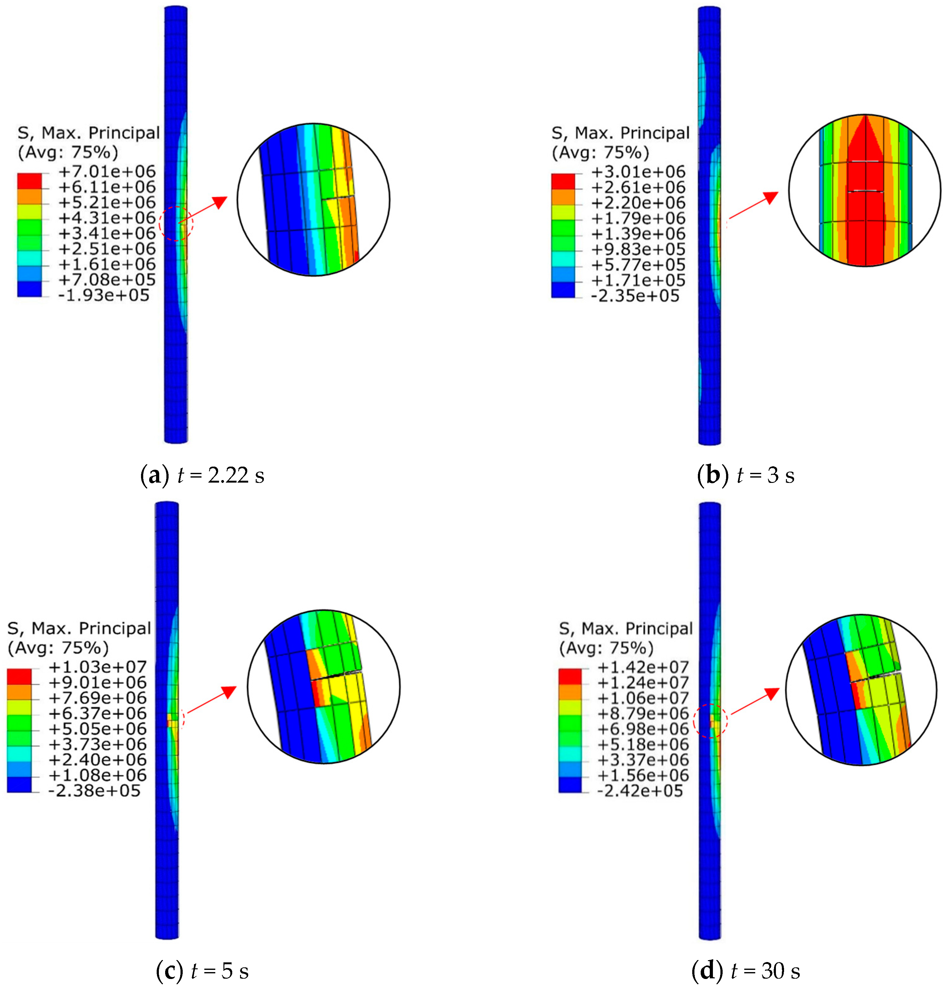
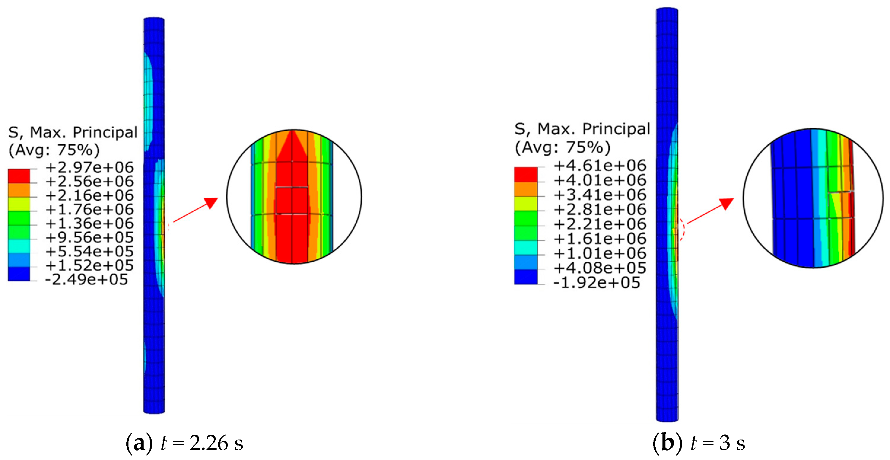
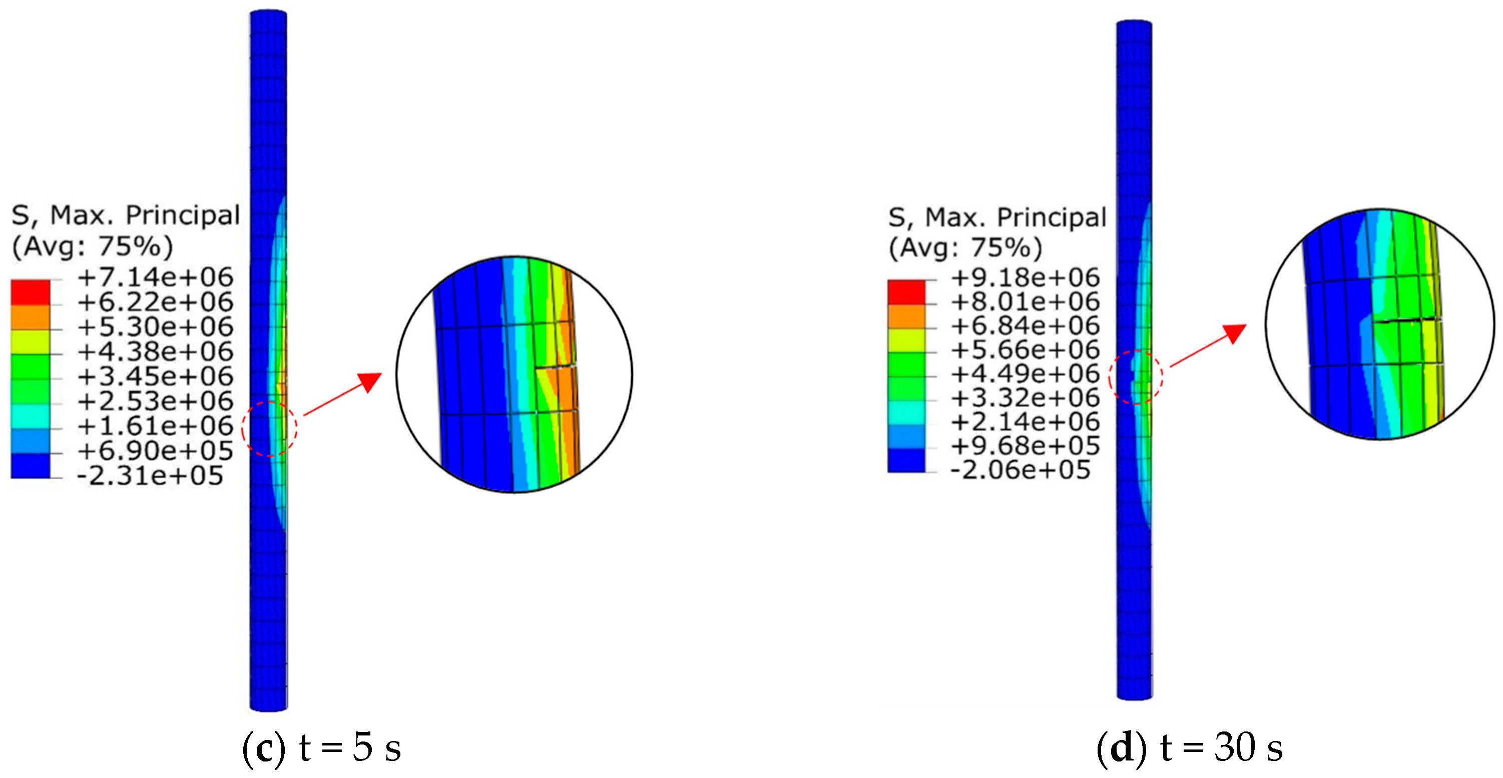
Figure 11 and Figure 12 show the propagation of cracks in the piles for the pile-supported and pile-anchor-supported conditions. Under seismic loading, the piles undergo bending due to slope deformation. As a result, one side of the pile experiences tension while the other side experiences compression. When the maximum principal stress exceeds the tensile strength of the pile, cracks initiate. For the pile-supported slope, a crack occurs at a depth of 7.75 m when t = 2.22 s, which is located at 1.75 m below the slip surface (Figure 11). For the pile-anchor-supported slope, a crack in the pile first appears at t = 2.26 s, located at a depth of 7.25 m (Figure 12). It seems that crack initiation in the pile body for both of the two support conditions occurs when the peak ground acceleration arrives. Then, the cracks gradually expand with continuous seismic loading. The maximum opening of the cracks in the pile-supported and pile-anchor-supported conditions are 0.98 and 0.36 mm, respectively.
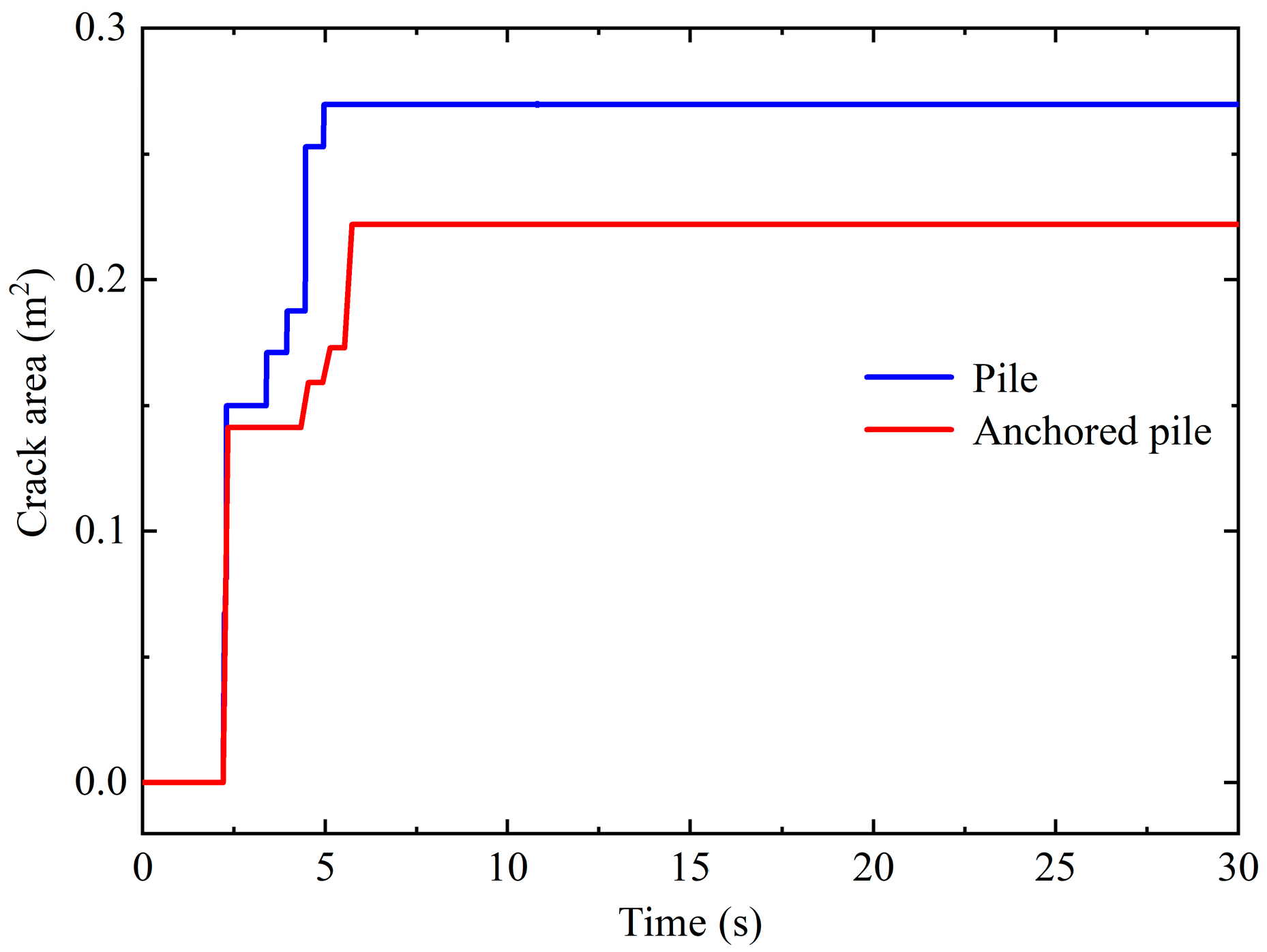
The output module ‘STATUSXFEM’ in ABAQUS is employed to output the node information of damaged units. The crack area is computed by summing the cross-sectional area of the damaged units. Figure 13 presents the evolution of cracks in the pile under seismic loading. The results indicate that crack growth in the pile body completes in a very short period, with two distinct increments of crack area observed. The first increment occurs when the peak ground acceleration arrives and is significantly larger than the second increment. Crack growth mainly happens during periods of significant changes in seismic acceleration amplitudes. The total crack areas for the pile-supported and pile-anchor-supported conditions are 0.27 m2 and 0.22 m2, respectively. According to Figure 11, Figure 12 and Figure 13, we can conclude that the anchors perform well in constraining crack growth in the piles. Under seismic loading, the failure pattern of the piles is tensile damage. Cracks initially emerge near the slip surface after the peak acceleration. Cracks in the pile body significantly weaken the performance of piles. Consequently, for the seismic design of piles, it is crucial to ensure the arrangement of stirrups near the concrete piles around the slip surface.

5. Conclusions

In this work, the dynamic behavior of a pile-anchor reinforced slope is studied using the finite element method (FEM). Three different reinforcement schemes, which include no support, pile support, and pile-anchor support, are considered to examine the performance of the pile-anchor structure. We compare the performances of different structures on the effectiveness of stabilizing the slope. The failure process of the pile is investigated using the XFEM.
The results show that the pile-anchor structure not only restrains overall slope deformation but also enhances the stiffness of the soil behind the piles. Under seismic shaking, the anchors experience rapid increments in the axial force when the peak ground acceleration arrives. The maximum shear force and bending moment of the piles for the pile-anchor-supported condition are much lower than those for the pile-supported condition, highlighting the effectiveness of the pile-anchor structure in improving the stress state of the piles and preventing bending damage during earthquakes.
The XFEM proves to be effective for predicting the formation and evolution process of cracks in piles subjected to seismic loading. Crack initiation in the pile body for both the pile supported and the pile-anchor-supported conditions occurs when the peak ground acceleration arrives, and then the cracks gradually expand into the pile body. Crack growth in the piles is completed in a very short period of time, with two distinct increments of crack area observed. The first increment occurs when the peak ground acceleration arrives and is significantly larger than the second increment. The simulations show that the FEM offers a useful tool for simulating the failure process of piles. The novelty of this work is that we realize the simulation of crack initiation and propagation in piles subjected to seismic loading.
The position, length, and spacing of piles and the inclination angles of anchors all influence the stability of slopes. In addition, vertical components of earthquakes also strongly influence slope stability. However, these influencing factors are not considered in this work. Further research on the influence of these factors on the dynamic response of stabilized slopes will be conducted.

Author Contributions

Conceptualization, Y.L.; Methodology, Y.L. and Z.C.; Software, Z.C. and L.Z.; Validation, Y.L. and Z.C.; Formal Analysis, Y.L. and Z.C.; Investigation, Z.C. and L.Z.; Resources, Y.L.; Data Curation, Y.L. and Z.C.; Writing—Original Draft Preparation, Y.L., Z.C., L.Z., and Y.H.; Writing—Review and Editing, Y.L., Z.C., L.Z., and Y.H.; Visualization, Y.H.; Supervision, Y.L.; Project Administration, Y.L.; Funding Acquisition, Y.L. All authors have read and agreed to the published version of the manuscript.

Funding

This work was financially supported by the National Key Research and Development Project of China (No. 2019YFC1509702) and the Opening Fund of Xinjiang Key Laboratory of Geohazard Prevention (No. XKLGP2022K04).

Data Availability Statement

Data will be made available on request.

Conflicts of Interest

The authors declare that they have no conflict of interest to this work.

References

  1. Huang, Y.; Xu, X.; Mao, W. Numerical performance assessment of slope reinforcement using a pile-anchor structure under seismic loading. Soil Dyn. Earthq. Eng. 2020, 129, 105963. [Google Scholar] [CrossRef]
  2. Wang, Y.; Wang, F.; Zhang, X. Application of small-diameter steel tube soldier piles in slope emergency works. Drill. Eng. 2022, 49, 152–157. [Google Scholar]
  3. Sun, J.; Fan, M.; Li, X. Combined supporting system of the slope protection pile and the compound soil nail wall with micro steel pipe piles. Drill. Eng. 2021, 48, 116–124. [Google Scholar]
  4. Xu, C. Landslide seismology geology: A sub-discipline of environmental earth sciences. Eng. Geol. 2018, 26, 207–222. [Google Scholar]
  5. Zhou, D.P.; Zhang, J.J.; Tang, Y. Seismic damage analysis of Roda slopes in Wenchuan earthquake. Chin. J. Rock Mech. Eng. 2010, 29, 565–576. [Google Scholar]
  6. Xu, X.; Huang, Y. Parametric study of structural parameters affecting seismic stability in slopes reinforced by pile-anchor structures. Soil Dyn. Earthq. Eng. 2021, 147, 106789. [Google Scholar] [CrossRef]
  7. Huang, Y.; Xu, X.; Liu, J.; Mao, W. Centrifuge modeling of seismic response and failure mode of a slope reinforced by a pile-anchor structure. Soil Dyn. Earthq. Eng. 2020, 131, 106037. [Google Scholar] [CrossRef]
  8. Hu, H.Q.; Huang, Y.; Xiong, M.; Zhao, L.Y. Investigation of seismic behavior of slope reinforced by anchored pile structures using shaking table tests. Soil Dyn. Earthq. Eng. 2021, 150, 106900. [Google Scholar] [CrossRef]
  9. Xu, M.; Tang, Y.; Liu, X.; Yang, H.; Luo, B. A shaking table model test on a rock slope anchored with adaptive anchor cables. Int. J. Rock Mech. Min. Sci. 2018, 112, 201–208. [Google Scholar] [CrossRef]
  10. Qu, H.L.; Luo, H.; Hu, H.G.; Jia, H.Y.; Zhang, D.Y. Dynamic response of anchored sheet pile wall under ground motion: Analytical model with experimental validation. Soil Dyn. Earthq. Eng. 2018, 115, 896–906. [Google Scholar] [CrossRef]
  11. Jahromi, H.F.; Jafarzadeh, F.; Zakaria, M.S. Experimental study of burial depth effect on embedded pipe deformations in sandy slopes under dynamic landsliding. Soil Dyn. Earthq. Eng. 2018, 114, 281–297. [Google Scholar] [CrossRef]
  12. Cheng, X.L.; Li, Y.F.; Wang, P.G.; Liu, Z.X.; Zhou, Y.D. Model tests and finite element analysis for vertically loaded anchors subjected to cyclic loads in soft clays. Comput. Geotech. 2020, 119, 103317. [Google Scholar] [CrossRef]
  13. Srilatha, N.; Latha, G.M.; Puttappa, C.G. Effect of frequency on seismic response of reinforced soil slopes in shaking table tests. Geotext. Geomembr. 2013, 36, 27–32. [Google Scholar] [CrossRef]
  14. Panah, A.K.; Eftekhari, Z. Shaking table tests on polymeric-strip reinforced-soil walls adjacent to a rock slope. Geotext. Geomembr. 2021, 49, 737–756. [Google Scholar] [CrossRef]
  15. Yang, Z.; Wang, J.; Xu, P. Stability analysis of deep fill slope under the influence of rainfall-surcharge coupling. Drill. Eng. 2023, 50, 94–102. [Google Scholar]
  16. Lin, Y.L.; Shi, F.; Yang, X.; Yang, G.L.; Li, L.M. Numerical analysis on seismic behavior of railway earth embankment: A case study. J. Cent. S. Univ. 2016, 23, 906–918. [Google Scholar] [CrossRef]
  17. Li, D.F.; Zhang, Z.J. The anti sliding mechanism of adjacent pile-anchor structure considering traffic load on slope top. Adv. Civ. Eng. 2021, 2021, 6615224. [Google Scholar] [CrossRef]
  18. Kiani, K. Nanomechanical sensors based on elastically supported double-walled carbon nanotubes. Appl. Math. Comput. 2015, 270, 216–241. [Google Scholar] [CrossRef]
  19. Peng, L.X.; Liew, K.M.; Kitipornchai, S. Buckling and free vibration analyses of stiffened plates using the FSDT mesh-free method. J. Sound Vib. 2006, 289, 421–449. [Google Scholar] [CrossRef]
  20. Zhang, L.W.; Zhang, Y.; Liew, K.M. Modeling of nonlinear vibration of graphene sheets using a meshfree method based on nonlocal elasticity theory. Appl. Math. Model. 2017, 49, 691–704. [Google Scholar] [CrossRef]
  21. Kiani, K. Column buckling of magnetically affected stocky nanowires carrying electric current. J. Phys. Chem. Solids. 2015, 83, 140–151. [Google Scholar] [CrossRef]
  22. Wang, L.; He, X.; Sun, Y.; Liew, K.M. A mesh-free vibration analysis of strain gradient nano-beams. Eng. Anal. Bound Elem. 2017, 84, 231–236. [Google Scholar] [CrossRef]
  23. Wu, Z.; Luo, G.; Yang, Z.; Guo, Y.; Li, K.; Xue, Y. A comprehensive review on deep learning approaches in wind forecasting applications. CAAI Trans. Intell. Technol. 2022, 7, 129–143. [Google Scholar] [CrossRef]
  24. Bong, T.; Kim, S.R.; Kim, B.I. Prediction of ultimate bearing capacity of aggregate pier reinforced clay using multiple regression analysis and deep learning. Appl. Sci. 2020, 10, 4580. [Google Scholar] [CrossRef]
  25. Gao, S.; Li, S. Bloody Mahjong playing strategy based on the integration of deep learning and XGBoost. CAAI Trans. Intell. Technol. 2021, 7, 95–106. [Google Scholar] [CrossRef]
  26. Cakiroglu, C.; Islam, K.; Bekdaş, G.; Nehdi, M.L. Data-driven ensemble learning approach for optimal design of cantilever soldier pile retaining walls. Structures 2023, 51, 1268–1280. [Google Scholar] [CrossRef]
  27. Gasparin, A.; Lukovic, S.; Alippi, C. Deep learning for time series forecasting: The electric load case. CAAI Trans. Intell. Technol. 2021, 7, 1–25. [Google Scholar] [CrossRef]
  28. Khan, J.; Lee, E.; Kim, K. A higher prediction accuracy–based alpha–beta filter algorithm using the feedforward artificial neural network. CAAI Trans. Intell. Technol. 2022, 1–16. [Google Scholar] [CrossRef]
  29. Hsiao, I.H.; Chung, C.Y. AI-infused semantic model to enrich and expand programming question generation. J. Artif. Intell. Res. 2022, 2, 47–54. [Google Scholar] [CrossRef]
  30. Benali, A.; Hachama, M.; Bounif, A.; Nechnech, A.; Karray, M. A TLBO-optimizedartificial neural network for modeling axial capacity of pile foundations. Eng. Comput. 2021, 37, 675–684. [Google Scholar] [CrossRef]
  31. Deng, Y.; Zeng, Z.; Jha, K.; Huang, D. Problem-Based Cybersecurity Lab with Knowledge Graph as Guidance. J. Artif. Intell. Res. 2022, 2, 55–61. [Google Scholar] [CrossRef]
  32. Jia, Z.; Wang, W.; Zhang, J.; Li, H. Contact High-Temperature Strain Automatic Calibration and Precision Compensation Research. J. Artif. Intell. Res. 2022, 2, 69–76. [Google Scholar]
  33. Cai, F.; Ugai, K. Numerical Analysis of the Stability of a Slope Reinforced with Piles. Soils Found. 2000, 1, 73–84. [Google Scholar] [CrossRef]
  34. Won, J.; You, K.; Jeong, S.; Kim, S. Coupled effects in stability analysis of pile–slope systems. Comput. Geotech. 2005, 32, 304–315. [Google Scholar] [CrossRef]
  35. Lin, Y.L.; Cheng, X.M.; Yang, G.L.; Li, Y. Seismic response of a sheet-pile wall with anchoring frame beam by numerical simulation and shaking table test. Soil Dyn. Earthq. Eng. 2018, 115, 352–364. [Google Scholar] [CrossRef]
  36. Joorabchi, A.E.; Liang, R.Y.; Li, L.; Liu, H.L. Yield acceleration and permanent displacement of a slope reinforced with a row of drilled shafts. Soil Dyn. Earthq. Eng. 2014, 57, 68–77. [Google Scholar] [CrossRef]
  37. Ye, S.; Fang, G.; Zhu, Y. Model establishment and response analysis of slope reinforced by frame with prestressed anchors under seismic considering the prestress. Soil Dyn. Earthq. Eng. 2019, 122, 228–234. [Google Scholar] [CrossRef]
  38. Yan, M.J.; Xia, Y.Y.; Liu, T.T.; Bowa, V.M. Limit analysis under seismic conditions of a slope reinforced with prestressed anchor cables. Comput. Geotech. 2019, 108, 226–233. [Google Scholar] [CrossRef]
  39. Chakraborty, R.; Dey, A. Probabilistic assessment of seismic response of toe-excavated hillslopes retained using anchored sheet-pile-wall. Ain Shams Eng. J. 2022, 13, 101736. [Google Scholar] [CrossRef]
  40. He, Z.; Qin, Y.; Zhang, Y.; Xu, Y.; Li, X. Engineering geological characteristics of completely weathered argillaceous limestone under the influence of water content and analysis of pile hole stability. Drill. Eng. 2023, 50, 84–93. [Google Scholar]
  41. Li, C.D.; Wang, X.Y.; Tang, H.M.; Lei, G.P.; Yan, J.F.; Zhang, Y.Q. A preliminary study on the location of the stabilizing piles for colluvial landslides with interbedding hard and soft bedrocks. Eng. Geol. 2017, 224, 15–28. [Google Scholar] [CrossRef]
  42. Xu, X.; Xing, Y.C.; Guo, Z.; Yu, H. Stability analysis of rainfall-triggered toe-cut slopes and effectiveness evaluation of pile-anchor structures. J. Earth Sci. 2021, 32, 1104–1112. [Google Scholar] [CrossRef]
  43. Mitani, Y.; Wang, F.; Okeke, A.C.; Qi, W.H. Dynamic analysis of earthquake amplification effect of slopes in different topographic and geological conditions by using ABAQUS. Prog. Geo Disaster Mitig. Technol. Asia 2012, 469–490. [Google Scholar]
  44. Shooshpasha, I.; Amirdehi, H.A. Evaluating the stability of slope reinforced with one row of free head piles. Arab. J. Geosci. 2015, 8, 2131–2141. [Google Scholar] [CrossRef]
  45. Wei, W.B.; Cheng, Y.M. Strength reduction analysis for slope reinforced with one row of piles. Comput. Geotech. 2009, 36, 1176–1185. [Google Scholar] [CrossRef]
  46. Haghani, M.; Neya, B.N.; Ahmadi, M.T.; Vaseghi, A.J. A new numerical approach in the seismic failure analysis of concrete gravity dams using extended finite element method. Eng. Fail. Anal. 2022, 132, 105835. [Google Scholar] [CrossRef]
  47. Huang, H.; Zeng, Z.C.; Zhang, F.; Zeng, Z.C. Mechanical behavior and influencing factors of different pile-anchor supporting structures. J. Highw. Transp. Res. Dev. 2015, 32, 58–66. [Google Scholar] [CrossRef]
  48. Liu, X.Y.; Cai, G.J.; Liu, L.L.; Zhou, Z.J. Investigation of internal force of anti-slide pile on landslides considering the actual distribution of soil resistance acting on anti-slide piles. Nat. Hazards 2020, 102, 1369–1392. [Google Scholar] [CrossRef]
  49. Ye, S.H.; Huang, A.P.; Fang, G.W. Dynamics of loess multi-level high fill slope under horizontal earthquake response law and stability analysis. Technol. Earthq. Disaster Prev. 2020, 1, 1–10. [Google Scholar]
  50. Lin, Y.L.; Li, Y.X.; Yang, G.L.; Li, Y. Experimental and numerical study on the seismic behavior of anchoring frame beam supporting soil slope on rock mass. Soil Dyn. Earthq. Eng. 2017, 98, 12–23. [Google Scholar] [CrossRef]
  51. Lin, Y.L.; Li, Y.X.; Zhao, L.H.; Yang, T.Y. Investigation on seismic response of a three-stage soil slope supported by anchor frame structure. J. Cent. South Univ. 2020, 27, 1290–1305. [Google Scholar] [CrossRef]
  52. Xie, J.; Duan, L.; Li, Y.T.; Yan, J.; Peng, J.J. Shock absorption analysis based on the tunnel-soil-surface building interaction system. J. Asian Archit. Build. 2022, 21, 1545–1560. [Google Scholar] [CrossRef]
  53. Zhuang, h.y.; Hu, z.h.; Wang, x.j.; Chen, G.X. Seismic responses of a large underground structure in liquefied soils by FEM numerical modelling. Bull. Earthq. Eng. 2015, 13, 3645–3668. [Google Scholar] [CrossRef]
  54. Machaček, J.; Triantafyllidis, T.H.; Staubach, P. Fully coupled simulation of an opencast mine subjected to earthquake loading. Soil Dyn. Earthq. Eng. 2018, 115, 853–867. [Google Scholar] [CrossRef]
  55. Li, Y.H.; Guo, Z.; Jing, H.B.; Deng, Q.C. Failure effect of seismic faults and the slope stability along highways under seismic hazards based on dynamic finite element analysis and genetic algorithm. Geotech. Geol. Eng. 2021, 39, 5191–5200. [Google Scholar]
  56. Xu, X.; Huang, Y.; Yashima, A.; Du, X. Failure evolution process of pile-anchor reinforced rock slope based on centrifuge shaking table tests. Eng. Geol. 2022, 311, 106920. [Google Scholar] [CrossRef]
  57. Li, X.J.; Wang, X.M.; Zhang, J.W. Method for judging seismic stability state of soil slopes. Chin. J. Geotech. 2018, 40, 2096–2102. [Google Scholar]
  58. Fries, T.P.; Baydoun, M. Crack propagation with the extended finite element method and a hybrid explicit-implicit crack description. Int. J. Numer. Methods Eng. 2012, 89, 1527–1558. [Google Scholar] [CrossRef]
  59. Belytschko, T.; Black, T. Elastic crack growth in finite elements with minimal remeshing. Int. J. Numer. Meth. Eng. 1999, 45, 601–620. [Google Scholar] [CrossRef]
  60. Wang, X.L.; Liu, C.; Wang, H.; Liu, H.; Wu, H.A. Comparison of consecutive and alternate hydraulic fracturing in horizontal wells using XFEM-based cohesive zone method. J. Pet. Sci. Eng. 2016, 143, 14–25. [Google Scholar] [CrossRef]
  61. Guo, J.C.; Luo, B.; Lu, C.; Lai, J.; Ren, J.C. Numerical investigation of hydraulic fracture propagation in a layered reservoir using the cohesive zone method. Eng. Fract. Mech. 2017, 186, 195–207. [Google Scholar] [CrossRef]
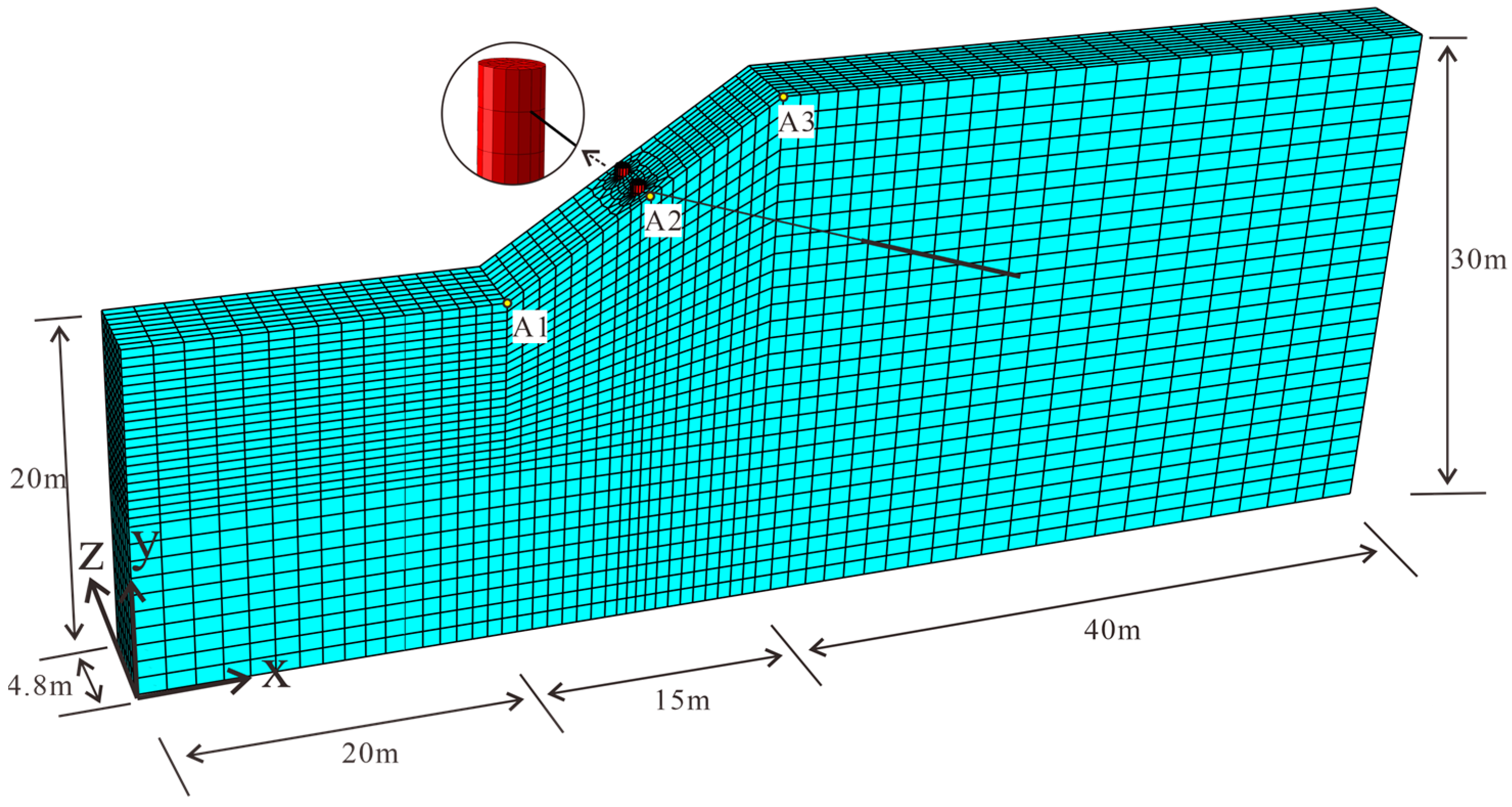
Figure 1. Slope model and finite element mesh (modified from Shooshpasha and Amirdehi [44]).
Buildings 13 02500 g001
Figure 2. Time histories of (a) acceleration and (b) displacement of the input seismic wave.
Buildings 13 02500 g002
Figure 3. Slip surface of the slope without reinforcement (FOS = 1.15).
Buildings 13 02500 g003
Figure 4. Acceleration time-history curves of the monitoring points within the unsupported slope.
Buildings 13 02500 g004
Figure 5. Equivalent plastic strain cloud diagram in the: (a) unsupported slope; (b) pile-supported slope; (c) pile-anchor-supported slope.
Buildings 13 02500 g005aBuildings 13 02500 g005b
Figure 6. Slope displacement cloud diagram in the: (a) unsupported slope; (b) pile-supported slope; (c) pile-anchor-supported slope (unit, m).
Buildings 13 02500 g006
Figure 7. Peak accelerations of the monitoring points under different support conditions.
Buildings 13 02500 g007
Figure 8. Time-history curves of the horizontal displacement measured in the slope reinforced by the pile-anchor structure.
Buildings 13 02500 g008
Figure 9. Pile behavior characteristics for the pile-supported and pile-anchor-supported slope models: (a) Shear force; (b) bending moment; (c) deflection.
Buildings 13 02500 g009
Figure 10. Time-history curves of the maximum axial force of the anchors with different prestresses.
Buildings 13 02500 g010
Figure 11. Propagation of cracks in the pile for the pile-supported condition.
Buildings 13 02500 g011
Figure 12. Propagation of cracks in the pile for the pile-anchor-supported condition.
Buildings 13 02500 g012aBuildings 13 02500 g012b
Figure 13. Time-history curves of pile crack area.
Buildings 13 02500 g013
Table 1. Parameter settings for the slope model [33,46,47].
MaterialDensity (Kg/m3)Elastic Modulus (MPa)Poisson’s RatioFriction Angle (º)Cohesion (KPa)
Soil20412000.352010
Pile246331,0000.2--
Anchor7800200,0000.25--
Disclaimer/Publisher’s Note: The statements, opinions and data contained in all publications are solely those of the individual author(s) and contributor(s) and not of MDPI and/or the editor(s). MDPI and/or the editor(s) disclaim responsibility for any injury to people or property resulting from any ideas, methods, instructions or products referred to in the content.