Abstract
In the shear design of corrugated steel web bridges, the shear stress distribution in the web is a more critical issue. In order to solve the calculation problem of shear stress distribution in corrugated steel webs, an energy-based method of calculating shear stress distribution in corrugated steel webs was proposed. This method uses the energy method as the basic principle, and through the basic idea that the external work is equal to the sum of the longitudinal strain energy and the transverse strain energy of the bridge, the proportion of shear force shared by each web is calculated, and the shear force distribution coefficient characterizes the proportion of shear force shared by each web. The method is applied to calculate the shear stress distribution coefficients of a single-box, six-cell corrugated steel web box girder bridge, and a finite element model of the bridge was established. The finite element calculation results were compared with the results of the energy method to analyze the accuracy of the shear force distribution coefficients of each web calculated by the energy method. The analysis results show that the method can analyze the shear force distribution between multiple corrugated steel webs more accurately and provide a basis for the shear design of this type of bridge.
1. Introduction
With the development of bridge design technology, waveform steel web-plate bridges have gained increasing popularity due to their aesthetic appeal, effective utilization of steel and concrete, rational structural form, and wide applicability. This type of structure combines the advantages of concrete compression and corrugated steel webs for shear resistance and makes full use of the materials, and it is a kind of economical-type bridge [1,2,3,4,5,6,7,8,9,10,11,12,13,14,15].
Due to its excellent overall performance, the steel box girder composite bridge with waveform steel webs has gained popularity in the field of bridge engineering, both domestically and internationally. Currently, researchers are primarily conducting theoretical and experimental studies on various aspects, including bending performance [16], shear behavior [17], torsion and distortion response [18,19], and dynamic characteristics [20,21].
Due to the relatively thin thickness of the waveform steel web, the shear deformation of the waveform steel web cannot be neglected when analyzing the mechanical behavior of waveform steel web composite box girders. He Jun et al. [22] assumed different rotations between the concrete flanges and the section, established a bending theory considering shear deformation, and analyzed the influence of a high span-to-depth ratio on beam deflection. Nie Jianguo et al. [23] considered the superposition of bending and truss actions to account for the bending behavior of waveform steel web composite box girders and proposed the effective stiffness method considering web shear deformation. Chen et al. [24] considered the local bending of the flanges and the shear deformation of the web and developed a nonlinear sandwich beam model for prestressed waveform steel web composite box girders.
Currently, there are three main methods for calculating shear stress in waveform web plates in academic research: The first method is to divide the total shear force of the section by the area of the waveform steel web plate to obtain the shear stress. Jia Shaoli et al. [25] found that this method is used in specifications from countries such as Japan, Europe, and the United States. However, the permissible shear stress values differ among these countries: China uses 155 MPa, Japan uses 205 MPa, Europe uses 160 MPa, and the United States uses 114 MPa. This method has a clear drawback in assuming that the shear force is entirely borne by the waveform web plate, while in reality, the top and bottom plates also contribute to carrying a certain amount of shear force. Research conducted by Zhou Man et al. [17], Liu Chao et al. [26], and others found that for cantilever beams, the proportion of shear force carried by the concrete top and bottom plates can reach nearly 50% at the fixed end. Therefore, this method of calculating shear stress is inaccurate for the steel web plate, leading to overestimated values, and it overlooks the proportion of shear force carried by the top and bottom plates, resulting in insufficient safety for the concrete top and bottom plates. The second method is to calculate shear stress based on the principles of material mechanics [27]. This theory provides reasonable accuracy for bridges with uniform cross-sections. However, due to the differences in the centroid positions of the cross-sections at both ends of bridges with variable cross-sections, both bending moments and axial forces generate self-consistent shear stresses that cannot be considered using this method. Therefore, it is not suitable for bridges with variable cross-sections. The third method is an extension of the second method, which takes into account the shear stresses generated by both bending moments and axial forces [28]. This method provides more accurate results, but it has not yet been widely applied to single-cell and multi-cell bridges.
Luo et al. [29] performed numerical simulations of the shear-carrying capacity of waveform web-plate beams using the nonlinear finite element method, establishing an ideal elastoplastic material model that conforms to the von Mises yield criterion. Wei et al. [30] derived shear flow calculation formulas for the cantilevered section of a waveform steel web-plate box girder under restrained torsion, further elucidating the distribution of free torsional shear stress and distortional torsional shear stress. Elgaaly et al. [5] conducted an experimental study on the failure of corrugated web beams under punching loads. The cause of the failure is the destruction of the web or the web yielding. At the same time, the finite element model was used to analyze the specimens, and parametric research was carried out. A simple design equation was deduced. The influence of in-plane bending or shear on the bearing capacity was analyzed, and design suggestions were put forward.
Scholars such as Li Shi et al. [31] used finite element simulations to study the shear performance of composite beams with corrugated steel webs in the case of nonlinearity while considering the effects of large deformation and initial defects. Research shows that the shear resistance of corrugated steel webs is significantly better than that of ordinary steel web beams. Song Jianyong et al. [32] used finite element simulations to study the shear buckling performance of composite beams with corrugated steel webs, while considering the effects of dimensional and thickness defects. Studies have shown that the ultimate shear buckling load of corrugated webs is sensitive to small-dimensional defects but less sensitive to thickness defects. Abbas et al. [33] proposed the shear capacity equation based on the classical plate theory, the orthotropic plate theory, the systematic analysis of the existing data, and two full-scale waved web beam experiments to re-evaluate and revise the proposed shear design equation. Nie Jianguo et al. [34] led the experiment of eight corrugated steel web beams. Through finite element analysis, they pointed out the key factors affecting the shear strength and buckling strength of the corrugated web. At the same time, combining numerical analysis and theory, a simplified calculation formula for the shear buckling strength of corrugated steel plates was derived, and the previous experimental data of corrugated webs were used to verify the validity of the model. Zhou Man et al. [17] proposed the shear stress calculation theory of variable cross-section wavy webs, which can more accurately calculate the shear stress of variable cross-section wavy webs and calculate the shear force distribution between the web and the top and bottom plates. On this basis, Liu Chao et al. [26] deduced the calculation method of the shear stress of the corrugated steel web with a variable cross-section and took a cantilever beam as an example. At the same time, the finite element model was used to verify the effectiveness of the algorithm.
In addition to the shear deformation of the web plate, shear lag effects at the flange stiffener junction are fundamental mechanical behaviors observed in waveform steel web composite box girders. These effects can have significant adverse consequences, including non-uniform stress distribution, reduced bending stiffness, increased flange shear deformation, and alterations in vibration characteristics. To address shear lag, the energy variational method and the equivalent beam method have been developed as straightforward and effective analysis techniques. Researchers have extended the energy variational method by assuming a linear distribution of normal stress along the height of the beam’s flange, satisfying the assumption of a plane section, to analyze the shear lag effects in waveform steel web composite box girders. Li Lifeng et al. [35] presented analytical solutions for deflection and stress, considering shear lag effects, and investigated the influence of flange/web connection methods on strain energy. Through theoretical derivation, finite element analysis, and model experiments, Liu Baodong et al. [36] demonstrated the necessity of accounting for shear lag and shear deformation effects in deflection calculations for waveform steel web composite box girders. Ji Wei et al. [37] derived a shape function to address the warping caused by shear lag in waveform steel web box girders and proposed a deflection calculation method considering both shear lag and shear deformation. Cheng et al. [38] proposed deflection calculation formulas for single-cell and multi-cell waveform steel web composite box girders, assessing the impacts of shear lag and shear deformation on deflection. Ma Chi et al. [39] developed beam elements for analyzing shear lag and shear deformation based on analytical solutions of internal forces and displacements in waveform steel web composite box girders. Zhang Zichen et al. [40] considered different shear lag intensities in the upper and lower flanges, derived analytical solutions for the displacement of waveform steel web composite box girders, and investigated the effects of boundary conditions on shear lag coefficients and folding effects. Zhou Cong et al. [41] proposed an equivalent beam method for analyzing shear lag in waveform steel web composite box girders with variable cross-sections, examining the influence of the load type, span-to-width ratio, and beam/height ratio on shear lag coefficients.
Currently, there have been numerous research results on the calculation methods for shear stress in waveform steel web-plates. However, the shear force distribution among multiple chambers and their respective waveform web-plates remain unclear. Based on the energy method, a shear stress distribution calculation method for waveform steel web-plates is proposed, aiming to further investigate the shear resistance mechanism of waveform steel web-plates and provide a reference for improving the safety and accuracy of designs.
2. The Calculation Theory of Shear Force Distribution of Variable Cross-Section Corrugated Steel Webs Based on the Energy Method
The distribution of shear stress within a beam is more complex than that of normal stress. In an idealized beam with a constant cross-section, it is commonly assumed that the shear flow remains constant across the depth of the section. This assumption is based on the concept of ‘uniform shear stress distribution’. It implies that the shear forces are uniformly distributed along the depth of the beam, resulting in a constant shear stress across the entire cross-section. However, in reality, due to various factors such as changes in the cross-sectional shape, the presence of openings, or variations in material properties, the shear stress distribution may not be perfectly uniform. In such cases, more detailed analysis methods such as shear flow theory or finite element analysis are employed to determine the actual distribution of shear stress. Currently, both domestic and international researchers believe that the bending shear stress of a corrugated steel web-girder composite bridge is primarily borne by the corrugated steel web. However, extensive experimental studies have shown that the concrete top and bottom flanges also bear a significant portion of the shear force [4,5,6,7,8,9,10]. Therefore, when calculating the shear stress of the web, a simple shear stress formula cannot be used, as it would lead to significant errors.
According to the calculation theory of shear stress of variable cross-section corrugated steel webs proposed by Zhou Man [17] and Liu [26], the shear stress of variable cross-section corrugated steel webs can be calculated more accurately, but the shear force distribution between the webs cannot be accurately calculated. In order to make up for the shortcomings of the existing theory, this chapter puts forward the calculation theory of shear force distribution of variable cross-section corrugated steel webs based on the energy method [24]. Strain energy is the energy stored due to the deformation caused by changes in the shape or structure of the object. This energy is stored within the object and can be released when the load is removed. The energy stored when we bend, twist, or stretch comes from the work performed by the external forces applied to the body. During these deformation processes, the work performed by the forces we apply to the object converts energy into stored strain energy. When a load is applied to a body, the stored energy takes the form of strain energy. The energy method believes that the longitudinal bending strain energy of the bridge plus the transverse bending strain energy is equal to the work performed by the external force, as shown in Equation (1). Assuming the deflection curve of the transverse deformation of the bridge, using the Lagrangian multiplier method [24], Equation (1) can solve the value of each parameter by taking the partial derivative of the hypothetical parameter to 0 for the entire system, and then further obtain shear force distribution.
At the same time, a finite element model is established to verify the validity of the calculation theory and compared with the traditional shear flow theory. The theoretical accuracy of this paper is higher than that of the traditional shear flow calculation theory.
2.1. Deflection Curve and Deflection Surface
For a cantilever beam, given a unit load at the free end, using the principle of force method, the calculation of the bridge longitudinal deflection curve is as follows:
In the formula, E is the elastic modulus of concrete, I is the bending moment of inertia of the section, l is the full length of the bridge, and x is the distance between the selected point and the free end.
In each transverse direction, the bridge surface is bent transversely. Assuming that the curved surface of the transverse direction is a quartic curve, the deflection curve of the transverse bridge direction structure is as follows:
In the formula, a, b, c, d, and e are coefficients, and in Figure 1 below are the deflection of the corresponding web.
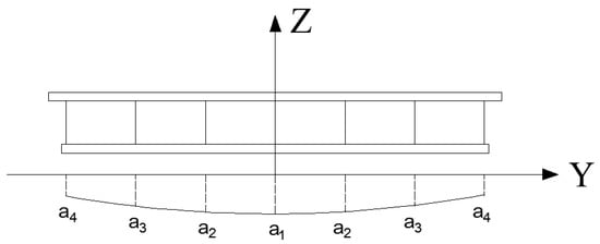
Figure 1.
Bridge lateral bending curve.
The deflection surface of the structure is when the load q is applied in the transverse bridge direction (y direction) at the cantilever end of the actual structure.
Assuming that the deflection surface can be approximately expressed as follows:
2.2. Longitudinal Bending Strain Energy
Taking the section of a single-box, six-chamber corrugated steel web in a certain actual project as an example, assuming the full bridge bending moment of inertia is I, the specific parameters and divisions of the section are shown in Figure 2, and the corrugated steel web sections are shown in Figure 3.

Figure 2.
Specific parameters and division of corrugated steel web section for single box and six chambers (unit: m).
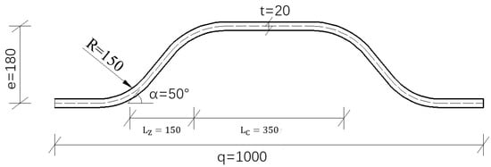
Figure 3.
Corrugated steel web sections (unit: mm).
Then, the bending moment of inertia of the i–th section is I (x direction), and the bending strain energy of the i–th beam along the bridge is as follows:
If there are n longitudinal beams, the calculation formula for the bending strain energy of the full bridge along the bridge direction is as follows:
2.3. Bending Strain Energy in the Transverse Direction
The transverse bridge structure can be regarded as composed of many open-web beams, and the open-web beams are mainly shear deformation. The upper and lower chord sections cannot be regarded as integral rigid sections, so approximate conversions must be made. Consider taking out the concrete top and bottom plates and corrugated steel webs of the axial unit length of a chamber, as shown in Figure 4a, and the equivalent calculated bending moment is shown in Figure 4b below.

Figure 4.
Diagram for calculation of bending moment of inertia of bridge unit transverse direction. (a) Unit segment. (b) Equivalent calculation of moment diagram.
Assuming that one side is just connected and the other side applies a unit force P, the deflection of the web on the side applying unit force can be obtained using the graph multiplication method:
In the formula, is the elastic modulus of the steel plate, is the elastic modulus of concrete, is the bending moment diagram under the action of the unit force, and is the bending moment diagram under the action of the external force . is the bending moment of inertia of the concrete top and bottom plate, and is the bending moment of inertia of the corrugated steel web. The reason for multiplying by 1/2 is that the stiffness of each web is equally divided by the chambers on both sides.
According to the research of Li Yale, the equivalent out-of-plane moment of inertia of the corrugated steel web is calculated as follows:
In the formula, is the elastic modulus of the steel plate, is the elastic modulus of the concrete, is the thickness of the corrugated steel web, is the inclination of the inclined slab section of the web, is the wave height, is the length of the straight slab, is the inclined slab segment projection length, and is the wavelength, as shown in Figure 3.
With , the equivalent generation method can be used to calculate the equivalent bending stiffness of the transverse bridge.
Next, the bending strain energy in the transverse direction can be calculated, and the calculation diagram is shown in Figure 5:
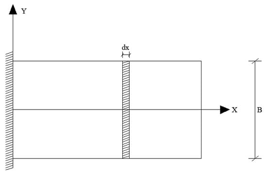
Figure 5.
Calculation scheme of beam transverse bending strain energy.
Take a beam with a width of dx, and assuming that the bending moment of inertia per unit length of the beam is known, the bending strain energy of the beam is as follows:
So, the transverse bending strain energy of the full bridge is as follows:
2.4. Calculation of Work of External Force
In the case that the free end of the actual structure is subjected to the load of equal wiring, the external force is calculated as follows:
2.5. Parameter Calculation
The variables in the equation are assumed to be five coefficients, a, b, c, d, and e, of the deflection curve in the transverse direction, using the Lagrangian multiplier method, and the whole system can be solved if the partial derivative of the coefficient is zero. Find the value of each coefficient.
where is the coefficient in , the above equation can be solved.
2.6. Shear Distribution Coefficient
According to Equation (1), if the shear force is , the bridge deflection curve equation is as follows:
In the formula, is the deflection curve equation when subjected to shear .
For each beam, the following expression can be written:
In the formula, is the shear force allocated to the i-th beam.
Divide (14) by (15) to achieve the following:
Therefore, the shear distribution coefficient of the i-th beam is as follows:
2.7. Shear Stress of Each Web
According to the calculation theory of shear stress proposed by Zhou Man et al., [17], the average shear stress of the section is calculated as τ, and the average shear stress of each web can be calculated according to the following formula:
In the formula, is the magnitude of the shear stress of the i-th beam, n is the number of single-box, multi-chamber section webs, and is the shear force distribution coefficient of a single web in Equation (17).
3. Shear Flow Theory
According to the basic principles of material mechanics [16], shear stress does not have a significant influence on deformation. Therefore, the method of deriving normal stress cannot be used to calculate shear stress. Instead, the shear stress theorem is employed to convert the calculation of shear stress on a cross-section into the calculation of shear stress on a longitudinal section because the situation of longitudinal stress is relatively clear. For an open section, the magnitude of shear flow at a certain location on the section can be calculated using the following formula:
Among them, q is the shear flow Q is the shear force on the section;, is the static moment at a certain position of the section, and I is the moment of inertia of the section.
For the closed corrugated steel web box girder section, Formula (18) becomes inapplicable, but the principle of the force method can be used to open each box chamber and add a virtual shear flow to create an open section throughout. The displacement coordination conditions at the structural opening can be used to obtain the virtual shear flow and then the size of the actual cross-sectional shear flow.
As shown in Figure 6, taking a thin-walled box girder with multiple boxes as an example, the original closed box room shear stress solution problem (a) can be decomposed into open box room shear stress (b) and closed box room unknown shear flow (c). Assuming that the shear flow distribution formed on the box girder section under the action of the shear force Q is , then can be calculated by Equation (20).
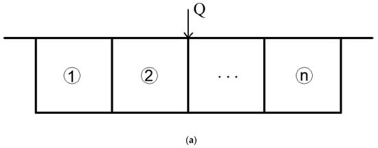
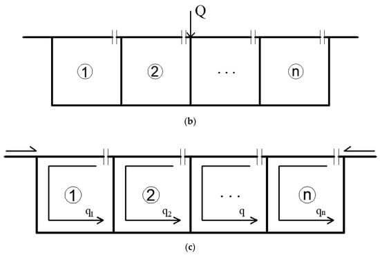
Figure 6.
Diagram of solving actual shear flow of corrugated steel web. (a) Shear stress of closed box chamber. (b) Shear stress of virtual open box room. (c) Unknown shear flow in virtual open chamber.
Since the three-box and three-chamber section is symmetrical, the bending center of the section is on the axis of symmetry, the origin of the coordinates is established at the bending center, and the direction of shear flow is specified according to Figure 6c.
According to the principle of the force method, at each incision, there should be no relative displacement on both sides of the incision. According to this, on each web, the strains caused by external forces and are and , respectively. List the following equation:
In the following formula: is the shear modulus, is the shear flow in the k-th chamber, integral represents the closed-circuit integral along the periphery of the i-th chamber, integral represents the i-th chamber integral with the common wall of the k-th room, and t is the thickness of the corresponding wall section.
According to the characteristics of the actual corrugated steel web bridge, first make assumptions about the calculation model to simplify the calculation: (1) Every part of the top slab has the same thickness except for the web. (2) The cross-section web at the same position has the same width and height. (3) The bottom plate has the same thickness. (4) For the corrugated steel web bridge, because the corrugated steel web is very thin (top and bottom plate thickness/web thickness > 20), it can be considered that the static moment at both ends of the corrugated steel web is constant. First, calculate the origin of the main axis of the section according to Formula (4), as shown in Figure 7. Suppose the distance between the origin of the spindle and the bottom plate of the box beam is H, then the requirements for the spindle are as follows:

Figure 7.
Calculation diagram.
That is, the static moment calculated for the entire section of the x-axis is 0, which is as follows:
Find H after simplification:
Then, calculate the distribution of the assumed opening section. Since only the law of web shear distribution in the bending state of a thin-walled box girder is studied, the torsion of the box girder is not considered for the time being, so the shear flow of the box girder can be obtained by the formula .
For a certain section of H, since is a constant, the distribution of can be obtained by only requiring the static moment, , to be distributed along the section. For the corrugated steel web section, the wall thickness is equal in sections, and the section profile is composed of straight lines, so it can be simply calculated according to the following formula:
After obtaining the contour integral, , , , and can be obtained, respectively, according to the simultaneous equations of Equation (20). For the shear stress, , on each web, the shear force distribution coefficient can be calculated by the following formula:
4. Finite Element Calculation Model
In order to further highlight the influence of the bending moment on the web shear stress, this paper selects the beam length 50 m, the cross section is a variable cross-section single-box, six-chamber corrugated steel web section, the structure type is a cantilever beam, and ABAQUS v.2020 is selected. The schematic diagram of the finite element model is shown in Figure 8. The free end section is a small section; the fixed end is a large section; the middle section parameters are linearly transitioned; and the box girder section parameters are shown in Figure 2. A vertical concentrated force of 1000 kN is applied to the free end of the cantilever beam. The schematic diagram of the corrugated steel web is shown in Figure 3. In terms of the material selection, this model only uses two materials: steel and concrete, both of which are assumed to be in a linear elastic state and isotropic materials. At the same time, the degree of freedom of the contact surface between the concrete top and bottom plate and the corrugated steel web is coupled to simulate the state of no axial slip. In terms of grid division, the concrete roof and bottom plates use a spatial 3D grid, and the corrugated steel web uses a flat 2D grid. A total of 276,201 nodes and 207,023 elements are planned. The material property settings are shown in Table 1.

Figure 8.
Finite element model.

Table 1.
Parameters of cantilever beam.
5. Result Analysis
5.1. Comparative Analysis of Shear Distribution Coefficient
For the cantilever beam, the calculation results of the energy method calculation Formulas (2)–(17), the traditional shear flow theory Formulas (19)–(25), and the finite element (FEM) method proposed in this paper are given for accuracy comparison. For the finite element calculation results, Formula (25) is used to calculate the shear distribution coefficient :
In the formula, is the shear stress of the middle web, the second middle web, the second side web, and the side web.
The definition of each web is shown in Figure 9. In research, the shear stress distribution is usually obtained in the regions or critical sections of interest. The specific sections to be considered depend on the research objectives and the characteristics of the structure. For example, in beam structures, it may be important to focus on the shear stress distribution at specific cross-sections, while in complex three-dimensional structures, the shear stress distribution throughout the entire structure may need to be considered. In order to avoid the influence of complex stress at the end, the bridge length of 40 m is cut as shown in Figure 9, and the section is taken every meter to calculate the shear stress.
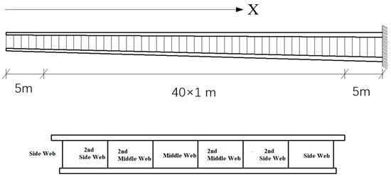
Figure 9.
Section selection and web definition.
The results of the finite element model are shown in Figure 10. Two conclusions can be drawn from Figure 10: (1) The shear stresses of the webs of the single-box, multi-chamber sections are not equal, and there is obvious shear force distribution among the webs. The shear force distribution coefficient of the middle web is the largest; the closer to the side web, the smaller the shear force distribution coefficient; and the side web shear force distribution coefficient is the smallest. (2) The shear force distribution coefficient is not constant, but it changes with the distance from the free end. The change law of the shear distribution coefficient of the middle web and the secondary web is: as the distance from the free end increases; the change law of the shear force distribution coefficient of the secondary web is: as the distance from the free end increases, the shear force distribution coefficient of the slab decreases first and then increases; the change law of the shear distribution coefficient of the side web is: it decreases as the distance from the free end increases.

Figure 10.
Shear coefficient calculated by FEM model.
The results of the shear flow method are shown in Figure 11, and three main conclusions can be drawn from Figure 11: (1) The shear flow method can calculate the shear force distribution coefficient of each web, and it can clearly reflect the shear force distribution. As a result, the shear force distribution coefficient of the middle web is the largest, and the closer the edge web is, the smaller the shear force distribution coefficient is, and the edge web shear distribution coefficient is the smallest. (2) From the change law of the shear force distribution coefficient, the shear force flow method is completely opposite to the finite element results. The shear force distribution coefficients of the middle web, the secondary web, and the secondary web all increase as the distance from the free end increases. At large, the shear distribution coefficients of the side webs all decrease as the distance from the free end increases.

Figure 11.
Shear coefficient calculated by shear flow method.
The results of the energy method are shown in Figure 12. Two conclusions can be drawn from Figure 12: (1) The shear flow method can calculate the shear distribution coefficient of each web and clearly reflect the shear distribution effect. The mid-web shear distribution coefficient is the largest; the smaller the shear distribution coefficient of the side webs, the smallest the shear distribution coefficients of the side webs. (2) From the change law of the shear force distribution coefficient, the results of the shear flow method and the finite element method are different, and the shear force distribution coefficient of each web basically does not change with the increase of the distance from the free end.

Figure 12.
Shear coefficient calculated by energy method.
The comparison between the energy method, the traditional shear flow method, and the finite element FEM proposed in this paper is shown in Figure 13. Figure 13a–d are the middle web, the secondary web, and the secondary side and show a comparison result of the web and the side web. Five conclusions can be drawn from the figure: (1) The shear force distribution coefficient of each web in the shear flow method varies with the distance from the free end, which is contrary to the finite element result. The shear force distribution coefficient of the web in the energy method basically does not vary with the distance. (2) Within the span range, the web shear distribution coefficient in the finite element method varies from 14.8% to 16.7%, the secondary web shear distribution coefficient varies from 15.2 to 16.3%, and the slab shear distribution coefficient varies from 14.3 to 15.7%. The shear distribution coefficient of side webs varies from 9.8 to 12.7%. (3) Within the span range, the web shear distribution coefficient in the shear flow method varies from 15.1 to 15.5%, the secondary web shear distribution coefficient varies from 15.0 to 15.3%, and the secondary web shear distribution coefficient change from 14.5 to 14.6%. The shear distribution coefficient of side webs varies from 12.6 to 13.2%. (4) Within the span range, the web shear distribution coefficient in the energy method varies from 15.925 to 15.924% (changes only 0.001%), the secondary web shear distribution coefficient varies from 15.752 to 15.753% (changes only 0.001%), and the shear distribution coefficient of the secondary webs varies from 14.932 to 14.933% (changes only 0.001%). The distribution coefficient of side web shear force varies from 11.517 to 11.518% (change only 0.001%). (5) Overall, the accuracy of the energy method is higher than that of the shear flow method.

Figure 13.
Comparison of the shear force distribution coefficient of each web in FEM, shear flow method, and energy method. (a) Middle web. (b) Second middle web. (c) Second side web. (d) Side web.
5.2. Error Analysis
According to the analysis of the error between each web, it is calculated as Formula (27):
In the formula, is the result of the energy method or the shear flow theory calculation of the shear force distribution coefficient, and is the result of the finite element calculation of the shear force distribution coefficient.
According to the analysis of the overall average shear force distribution coefficient error σ, it is calculated as Formula (28):
In the formula, , , , and are the errors of the side web, the secondary web, the secondary web, and the middle web, respectively. The reason for adding the absolute value is as follows: if the absolute value number is not added, the positive and negative errors of the webs may cancel each other out, making the calculated average error less than the actual average error.
The error between the shear force distribution coefficient calculated by the energy method and the finite element is shown in Figure 14a, and the error between the shear force distribution coefficient calculated by the shear flow method and the finite element is shown in Figure 14b. The specific error range is shown in Table 2. Four conclusions can be drawn from the figure: (1) Overall, the energy method calculates the shear distribution coefficient and the finite element error is small, and the error distribution has no obvious law; the shear flow method and the finite element error are large; and as the distance from the free end increases, the error increases. (2) For the energy method, within the span range, the error of the middle web is from −4.6% to 7.4%, the error of the secondary web is from −3.6% to 2.8%, and the error of the secondary web is from −5.1% to 4.0%. The marginal web error ranges from −9.3% to 17.4%, and the overall average error ranges from 1.8% to 7.5%. For the shear flow method, within the span range, the error of the middle web is from −9.1% to 4.8%, the error of the secondary web is from −7.8% to 0.6%, and the error of the secondary web is from −7.8% to 1.4%. The marginal web error ranges from 0.4% to 35.2%, and the overall average error ranges from 0.8% to 14.9%. (3) From the point of view of subdivided webs, the energy method has a larger error with the side webs, and the closer to the fixed end, the greater the error; the maximum error exceeds 15%; the error with other webs is small; and the absolute value of the error is basically at 5%. Within, the shear flow method has a large error with the side webs; the maximum error exceeds 35%, and there are also large errors with other webs; the maximum error is close to 10%. (4) Regardless of whether it is a single web or as a whole, the energy method is more accurate than the shear flow method in calculating the shear distribution coefficient.
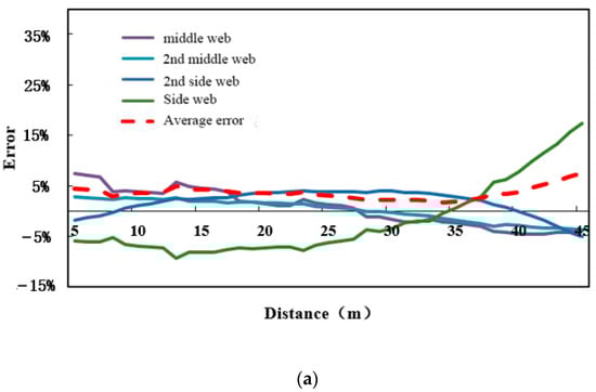
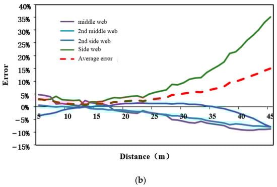
Figure 14.
Error analysis of the shear force distribution coefficient of each web in shear flow method and energy method. (a) Error analysis of energy method shear distribution coefficient. (b) Error analysis of shear distribution coefficient of shear flow method.
Table 2.
Errors analysis.
6. Conclusions
- (1)
- Taking the shear force distribution coefficient as the calculation reference standard, according to the finite element results, two conclusions can be clearly drawn: (a) There is an obvious shear force distribution phenomenon between the webs of the single-box, multi-chamber section, as the shear force distribution coefficient gradually decreases from the middle web to the side web. (b) The shear force distribution coefficient is not constant, but it changes with the distance from the free end.
- (2)
- Comparing the finite element model with the two calculation theories, four conclusions can be drawn: (a) The law of the shear force distribution coefficient of each web of the shear flow method varies with the distance from the free end, which is contrary to the finite element result. The shear force distribution coefficient of each web in the method basically does not change with the distance from the free end. (b) Generally speaking, the energy method calculates the shear force distribution coefficient, the finite element error is small, and the error distribution has no obvious law. The error with the finite element is larger, and as the distance from the free end increases, the error becomes larger. (c) From the perspective of subdivided webs, the energy method has a larger error with the side webs, and the closer to the fixed end, the greater the error; the maximum error exceeds 15%, and the other webs have smaller errors, and the absolute value of the error is basically 5%. Within, the shear flow method has a large error with the side webs; the maximum error exceeds 35%, and there are also large errors with other webs; the maximum error is close to 10%.
- (3)
- Regardless of whether it is a single web or a whole, the energy method is more accurate than the shear flow method in calculating the shear distribution coefficient. The energy method, based on the principle of conservation of energy, assumes linear material behavior and small deformations. In the case of corrugated steel webs, these assumptions may not always hold true, particularly under high shear loads or complex stress conditions, leading to potential discrepancies. The shear flow method, often used for thin-walled structures, assumes uniform shear stress distribution across the thickness, which might not be consistently accurate for corrugated steel web structures, especially under high shear flow or when the web thickness varies. The finite element method, a numerical approach, is susceptible to errors due to approximations in the numerical solution, definitions of boundary conditions, or simplifications in the material behavior or geometry of the structure. The quality and density of the mesh used in the finite element analysis can also significantly impact the accuracy of the results.
- (4)
- In the present study, the influence of torsion and distortion on the shear stress of waveform webs was not considered, and the folding effect of waveform webs could not be calculated. Further research should focus on these two aspects and conduct corresponding experimental verification and analysis.
- (5)
- By using the energy method to study the distribution of shear stress, we contribute to a deeper understanding of the behavior of beams under different loading conditions. The knowledge gained from our research can be applied to improve the accuracy of structural models and calculations, particularly when dealing with beams with non-uniform conditions or complex geometries. By considering the actual distribution of shear stress, designers can optimize the structural performance, ensure adequate load-bearing capacity, and prevent potential failure modes such as shear deformation or stress concentration.
- (6)
- The focus of this paper is to introduce the calculation method of the shear stress distribution coefficient for the waveform steel web-plate. Therefore, a parametric analysis of the relevant parameters of the waveform steel web-plate box girder bridge was not conducted. In the future, it is necessary to perform parameter analysis and experimental verification of factors that influence the shear stress performance of the waveform steel web-plate, such as the thickness of the steel web-plate, the thickness of the top and bottom plates, and the waveform of the steel web-plate. This will provide references for improving the theoretical analysis and design of such structures.
Author Contributions
Conceptualization, C.L. and Z.S.; methodology, C.L.; validation, C.L.; formal analysis, Z.S.; data curation, Z.S.; writing—original draft preparation, Z.S.; writing—review and editing, C.L. All authors have read and agreed to the published version of the manuscript.
Funding
This research received no external funding.
Data Availability Statement
Data are available upon request.
Conflicts of Interest
The authors declare no conflict of interest.
References
- Hendy, C.R.; Johnson, R. Designers’ Guide to EN 1994-2 Eurocode 4: Design of Composite Steel and Concrete Structures; General Rules and Rules for Bridges; Thomas Telford: London, UK, 2006; ISBN 0727731610. [Google Scholar]
- Units, C.U.S.; Edition, T. AASHTO LRFD Bridge Design Specifications; American Association of State Highway and Transportation Officials: Washington, DC, USA, 2010; ISBN 9781560514053. [Google Scholar]
- Abbas, H.H.; Sause, R.; Driver, R.G. Analysis of Flange Transverse Bending of Corrugated Web I-Girders under In-Plane Loads. J. Struct. Eng. 2007, 133, 347–355. [Google Scholar] [CrossRef]
- Elgaaly, M.; Hamilton, R.W.; Seshadri, A. Shear Strength of Beams with Corrugated Webs. J. Struct. Eng. 1996, 122, 390–398. [Google Scholar] [CrossRef]
- Elgaaly, M.; Seshadri, A. Girders with Corrugated Webs under Partial Compressive Edge Loading. J. Struct. Eng. 1997, 123, 783–791. [Google Scholar] [CrossRef]
- Elgaaly, M.; Seshadri, A. Depicting the behavior of girders with corrugated webs up to failure using non-linear finite element analysis. Adv. Eng. Softw. 1998, 29, 195–208. [Google Scholar] [CrossRef]
- Ibrahim, S.A.; El-Dakhakhni, W.W.; Elgaaly, M. Behavior of bridge girders with corrugated webs under monotonic and cyclic loading. Eng. Struct. 2006, 28, 1941–1955. [Google Scholar]
- Khalid, Y.A.; Chan, C.L.; Sahari, B.B.; Hamouda, A.M.S. Bending behaviour of corrugated web beams. J. Mater. Process. Technol. 2004, 150, 242–254. [Google Scholar] [CrossRef]
- Metwally, A.E.; Loov, R.E. Corrugated steel webs for prestressed concrete girders. Mater. Struct. 2003, 36, 127–134. [Google Scholar]
- Moon, J.; Yi, J.W.; Choi, B.H.; Lee, H.E. Lateral–torsional buckling of I-girder with corrugated webs under uniform bending. Thin-Walled Struct. 2009, 47, 21–30. [Google Scholar]
- Nguyen, N.D.; Han, S.R.; Kim, J.H.; Kim, S.N.; Kang, Y.J. Moment modification factors of I-girder with trapezoidal web corrugations under moment gradient. Thin Walled Struct. 2012, 57, 1–12. [Google Scholar]
- Nguyen, N.D.; Han, S.R.; Lee, G.S.; Kang, Y.J. Moment modification factor of I-girder with trapezoidal-web-corrugations considering concentrated load height effects. J. Constr. Steel Res. 2011, 67, 1773–1787. [Google Scholar]
- Nguyen, N.D.; Kim, S.N.; Han, S.R.; Kang, Y.J. Elastic lateral-torsional buckling strength of I-girder with trapezoidal web corrugations using a new warping constant under uniform moment. Eng. Struct. 2010, 32, 2157–2165. [Google Scholar] [CrossRef]
- Oh, J.-Y.; Lee, D.H.; Kim, K.S. Accordion effect of prestressed steel beams with corrugated webs. Thin Walled Struct. 2012, 57, 49–61. [Google Scholar]
- Romeijn, A.; Sarkhosh, R.; Hoop, H.D. Basic parametric study on corrugated web girders with cut outs. J. Constr. Steel Res. 2009, 65, 395–407. [Google Scholar]
- He, J.; Liu, Y.Q.; Wang, S.H.; Xin, H.; Chen, H.; Ma, C. Experimental Study on Structural Performance of Prefabricated Composite Box Girder with Corrugated Webs and Steel Tube Slab. J. Bridge Eng. 2019, 24, 04019047. [Google Scholar]
- Zhou, M.; Zhang, J.D.; Zhong, J.T.; Zhao, Y. Shear Stress Calculation and Distribution in Variable Cross Sections of Box Girders with Corrugated Steel Webs. J. Struct. Eng. 2016, 142, 04016022. [Google Scholar] [CrossRef]
- Deng, W.Q.; Mao, Z.L.; Liu, D.; Zhang, J.D. Analysis and Experimental Study on Torsion and Distortion of Single Box Three-Cell Cantilever Girder with Corrugated Steel Webs. J. Build. Struct. 2020, 41, 173–181. [Google Scholar]
- Liu, B.D.; Feng, W.Z.; Ren, H.W.; Li, P.F.; Mou, K. Experimental Study on Torsion and Distortion of Continuous Rigid Frame Bridge with Corrugated Steel Webs. China Railw. Sci. 2015, 36, 40–46. [Google Scholar]
- Ji, W.; Deng, L.; He, W. Vehicle-Bridge Coupled Vibration Analysis and Calculation of Dynamic Impact Factor for the PC Box-Girder Bridge with Corrugated Steel Webs. J. Vib. Eng. 2016, 29, 1041–1047. [Google Scholar]
- Yang, Z.Y.; Yang, M.; Rong, X.L.; Tian, L. Theoretical and Numerical Study on Dynamic Characteristics of Composite Trough Girder with Corrugated Steel Webs. J. Bridge Eng. 2021, 26, 0402100. [Google Scholar]
- He, J.; Liu, Y.Q.; Chen, A.R.; Wang, Q. Deflection Calculation of Composite Girder Bridge with Corrugated Steel Web with Consideration of Shear Deformation. J. Tongji Univ. Nat. Sci. Ed. 2009, 37, 440–444. [Google Scholar]
- Nie, J.G.; Li, F.X.; Fan, J.S. Effective Stiffness Method for Calculating Deflection of Corrugated Web Girder. Eng. Mech. 2012, 29, 71–79. [Google Scholar]
- Chen, X.C.; Bai, Z.Z.; Zeng, Y.; Jiang, R.J.; Au, F.T. Prestressed Concrete Bridges with Corrugated Steel Webs: Nonlinear Analysis and Experimental Investigation. Steel Compos. Struct. 2016, 21, 1045–1067. [Google Scholar] [CrossRef]
- Jia, Z.L.; Gao, S.Z.; Tao, M.X. Shear Design Method for Corrugated Steel Web of PC Compounding Box Girder. Highw. Eng. 2015, 40, 96–100+123. [Google Scholar]
- Chao, L.; Yuhao, H.; Zhan, G. Calculation of shear stress of corrugated steel web box girder with variable section. J. Tongji Univ. 2018, 47, 475–481. [Google Scholar]
- Department of Materials Mechanics, Tongji University. Mechanics of Materials; Tongji University Press: Shanghai, China, 1987. [Google Scholar]
- Li, J. Research on practical shear stress calculation of variable cross-section composited box-girder with corrugated steel webs. J. Railw. Sci. Eng. 2017, 14, 80–86. [Google Scholar]
- Luo, R.; Edlund, B. Shear capacity of plate girders with trapezoidally corrugated webs. Thin-Walled Struct. 1996, 26, 19–44. [Google Scholar] [CrossRef]
- Wei, N.; Zhang, Y.; Yao, X. Analysis on Restrained Torsional Shear Stresses of Box Girders with Corrugated Steel Webs. Appl. Math. Mech. 2020, 41, 386–395. [Google Scholar]
- Shi, L.; Yanlin, G. Study on the Shear Performance of Wave-folded Web Beam. J. Archit. Struct. 2001, 49–54. [Google Scholar] [CrossRef]
- Song, J.Y.; Zhang, S.R.; Lu, J.M. Simulation and Influence of Initial Defects in the Analysis of Shear Buckle of Corrugated Steel Web. Highw. Traffic Technol. 2004, 64–67. [Google Scholar]
- Abbas, H.H.; Sause, R.; Driver, R.G. Shear Strength and Stability of High Performance Steel Corrugated Web Girders. In Proceedings of the Annual Stability Conference, Research Council, San Antonio, TX, USA, 8–11 February 2006; pp. 1381–1392. [Google Scholar]
- Jianguo, N.; Liang, T. Nonlinear Analysis of Pure Torsion Property for Prestressed Concrete Composite Box Girders with Corrugated Steel Webs. Chin. J. Highw. 2007, 20, 71–77. [Google Scholar]
- Li, L.; Peng, K.; Wang, W. Theoretical and Experimental Study on Shear Lag Effect of Composite Box Girder with Corrugated Steel Webs. J. Highw. Transp. Res. Dev. 2009, 26, 78–83. [Google Scholar]
- Liu, B.; Ren, H.; Li, P. Deflection Analysis Considering the Characteristics of Box Girder with Corrugated Steel Webs. China Railw. Sci. 2011, 32, 21–26. (In Chinese) [Google Scholar]
- Ji, W.; Lin, P.Z.; Liu, S.Z. Deflection Calculation and Analysis of PC Box Girder Bridges with Corrugated Steel Webs. J. Southwest Jiaotong Univ. 2018, 53, 46–55. [Google Scholar]
- Cheng, J.; Yao, H. Simplified Method for Predicting the Deflections of Composite Box Girders. Eng. Struct. 2016, 128, 256–264. [Google Scholar] [CrossRef]
- Ma, C.; Liu, S.Z.; Wu, M.Q. Matrix Analysis of Composite Box Girder with Corrugated Steel Webs Considering Shear Deformation and Shear Lag Effect. China J. Highw. Transp. 2018, 31, 80–88. [Google Scholar]
- Zhang, Z.C.; Jin, X.; Gan, Y. Vertical Bending Mechanical Properties of Box Composite Girder with Corrugated Steel Webs. China Railw. Sci. 2019, 40, 52–59. [Google Scholar]
- Zhou, C.; Wang, J.Q.; Li, L.F. Bar Simulation Method for Shear Lag Analysis of Non-Prismatic Composite Box Girders with Corrugated Steel Webs. J. China Railw. Soc. 2022, 44, 143–152. [Google Scholar] [CrossRef]
Disclaimer/Publisher’s Note: The statements, opinions and data contained in all publications are solely those of the individual author(s) and contributor(s) and not of MDPI and/or the editor(s). MDPI and/or the editor(s) disclaim responsibility for any injury to people or property resulting from any ideas, methods, instructions or products referred to in the content. |
© 2023 by the authors. Licensee MDPI, Basel, Switzerland. This article is an open access article distributed under the terms and conditions of the Creative Commons Attribution (CC BY) license (https://creativecommons.org/licenses/by/4.0/).