Article

Numerical Study on Seismic Behavior of Demountable Joints Consisting of Reinforced Concrete Columns and Steel Beams

1
Jiangxi Guojing Construction Investment Co., Ltd., Zhangshu 331200, China
2
China Jiangxi International Economic and Technical Cooperation Co., Ltd., Nanchang 330038, China
3
College of Civil Engineering and Architecture, Wenzhou University, Wenzhou 325035, China
4
Key Laboratory of Engineering and Technology for Soft Soil Foundation and Tideland Reclamation of Zhejiang Province, Wenzhou 325035, China
*
Author to whom correspondence should be addressed.
Buildings 2023, 13(10), 2558; https://doi.org/10.3390/buildings13102558
Submission received: 14 September 2023 / Revised: 3 October 2023 / Accepted: 8 October 2023 / Published: 10 October 2023

Abstract

:
In this study, three new types of demountable connections, consisting of reinforced concrete columns and steel beams, are proposed, and their seismic performance is investigated through the use of cyclic loading tests. The test results reveal that these three demountable RCS joints show good seismic performance, in which the ductility coefficients of specimens RCS-1 and RCS-2 are improved by 69% and 109%, respectively, compared with the reference group of RCS-0 specimens. Various parameters, such as the beam flange thickness, bolt strength, and connecting steel strength, were analyzed using the finite element software ABAQUS 2021 to determine the effect of these parameters on the seismic performance and behavior of the connections. The results also show that the three demountable RCS joints are very sensitive to the variation in beam flange steel thickness, while the connector steel strength and bolt type have very little effect on the joint load-carrying capacity. In addition, different current theoretical approaches for calculating the shear bearing capacity in the panel zone of joints are discussed.

1. Introduction

Construction and demolition waste (C&DW) accounts for about 30% of global waste production, which can lead to heterogeneous ecological impacts such as the depletion of resource pools, global warming, and land degradation [1,2,3,4,5]. Ordinary buildings are usually designed as permanent structures, but the disposal of construction waste is quite difficult due to various demolition problems [6]. In recent years, many scholars have conducted in-depth studies on the application of post-demolition waste treatment for existing old buildings. For example, Fayed et al. [7] utilized steel mesh fabric constraints to improve the bonding properties of ribbed steel reinforcement embedded in recycled aggregate concrete, and Aksoylu et al. [8] used waste ceramic powder as a cement replacement and studied its application in reinforced concrete beams. Several scholars have also begun to pay attention to the reuse aspect of building components, but this has not yet entered into mainstream practice [9]. However, the application of demountable structures in building construction can allow for the reuse of building materials and reduce the waste of dismantling [10]; at the end of a building’s life cycle, once disassembled, these materials can then be reassembled to a new building, which has a good environmental and economic benefit. Compared with site-cast integrated components, the question of how to ensure the performance of demountable components to meet the requirements of the structural design becomes extremely important.
Considering that the connection of prefabricated components plays a crucial role in the performance of an entire demountable structure, the factory prefabricated components need to be of stable quality and, at the same time, minimize the difficulty of on-site construction and installation as much as possible. At the level of the joint failure mode, it has been concluded from the evaluation of past earthquake damage that the connections of prefabricated elements usually fail before the prefabricated elements themselves. Many studies have been conducted that investigate the behavior of demountable joints. The main existing studies focused on demountable steel structures are divided into the following two directions: on the one hand, beam or column members in demountable beam–column joints are spliced to achieve detachability. For example, Uy et al. [10] carried out finite element simulations and considered the parametric analysis of beam–beam connection, column–column connection, and beam–plate connection joints and proposed different innovative demountable beam–column connections; the computational results showed that when the load is no greater than 50% of the computed load, beam–column connection can be achieved. The calculation results showed that when the load is no greater than 50% of the calculated load, the function of the demountable cover beam in the beam–beam connection joint can be achieved. Additionally, the stiffness and ultimate tensile strength of the column–column demountable joint can be improved by increasing the sleeve length and reinforcement rate. Özkılıç et al. [11] proposed a new type of beam–column joint connection for flexural frames with replaceable reduced beam sections that not only have the advantages of a high versatility and the energy-consuming capacity of general flexural frame structures, but also greatly reduce the difficulty of assembly in field construction. This new connection can successfully replace energy-consuming members under the residual deformation of the frame after an earthquake, so the authors decided to extend its application to the intermediate splice section of eccentric braced frames [12,13]. Wang et al. [14] carried out an experimental study on the static and hysteresis performance of the proposed new demountable beam–column combined bolt joint, and parametric analysis was performed using the finite element model validated by the experimental results. Ataei et al. [15,16] also carried out an experimental study on a semi-rigid demountable joint with flush end plates between steel beams and steel tube columns. The experimental results showed that the joint has a good bending and rotation capacity, and the proposed structural system can be easily removed and used in other buildings once the previous building reaches the end of its service life. On the other hand, some existing studies focused on another direction, namely studying the control of joint damage in replaceable energy-consuming connectors. Lin et al. [17] focused on the beam–column joint outrigger beam region connected to the main beam using replaceable damage control fuses; the experimental results show that the fuses not only control the joint damage in the region but also serve as indicators for evaluating the degree of damage that is visible after an earthquake. R-RBS beam end splice steel joints can avoid welding in the field; Özkılıç et al. [18] carried out cyclic loading test and finite element analysis for this joint form, and the results show that this joint can meet the AISC code requirements.
To study the seismic performance of repaired demountable steel column–steel beam joints, Peng [19] first conducted a static test on the joints, and then they repaired the joints by removing and replacing the beams. The repaired steel column–steel beam joint was investigated using low circumferential repeated load tests. The test results demonstrate that the repaired joints show good seismic performance and meet the requirements of the seismic design codes. In addition, other scholars have considered the effect of concrete slabs on the seismic performance of steel frame structures. Vasdravellis et al. [20] analyzed the effect of partial combined action and partial strength connections of concrete slabs and steel beams on the ground vibration response of composite frames. Valent et al. [21] used the repairable fuse device to deal with the joints to consider the seismic performance of the slab, and the weakened steel plate was used as the fuse device at the web and flange of the steel beam. The effects of bolted and welded devices on the seismic response of combined steel frames were able to be deeply understood through the use of experiments and numerical simulations. In addition to demountable steel connections, demountable concrete connections have also been extensively studied. Xiao et al. [22] conducted five full-scale tests on beam–beam demountable connections with concrete frame side joints. The obtained results test results showed that the demountable concrete joints exhibited good ductility under both static and seismic loads. Ding et al. [23], who conducted a test study on seven full-size demountable concrete beam–column joints, demonstrated that the joints showed good seismic performance but poor ductility. In addition, the feasibility of recycling demountable concrete structures was verified during the construction process. Huang et al. [24] proposed the use of multi-seam devices to enhance the seismic performance of a demountable concrete beam–column connection joint. In addition, compared to the traditional pure steel beams and reinforced concrete beams, steel–concrete combination beams have stronger structural characteristics in terms of strength and stiffness. In recent years, to achieve the demountable connection between the concrete slab and the steel beam, in some research articles, in order to make dismantling convenient and improve the installation efficiency, it has been proposed to replace the use of traditional steel bolts nailed to a fixed steel–concrete combination of the concrete slab. Wang et al. [25] carried out experiments on the launching of concrete slab steel beams fixed with multiple bolted connections using a numerical model validation and parametric analysis. Malla et al. [26] numerically investigated bolted demountable connections between concrete shear walls. The results of their study showed that the bolted connection significantly affected the damage mode of the connection. As a result of the in-depth research of various scholars, shear connections different from ordinary shear bolts were proposed. He [27] and Loqman et al. [28] proposed the application of a demountable shear connection (LB-DSC and HTFGB) in steel–concrete composite structures, respectively. The results of the launching experiments and finite element simulation results show that compared with the other bolted shear connections, a shear connection with a high shear resistance and high stiffness was used, and the corresponding ultimate bearing capacity equations of the connectors were proposed.
On the other hand, the basis of the development of steel–concrete combined structures is derived from traditional concrete structures and steel structures, but their stress performance has greatly improved. For concrete structures, the addition of steel can result in a reduction in the self-weight of the structure, reduce the construction cross-section area, save formwork, speed up the construction process, etc. For steel structures, the addition of concrete can increase the fire resistance and durability of the structure, improve the overall stiffness of the structure, reduce the amount of steel, and reduce the cost [2]. The reinforced concrete column–steel beam (RCS) combination structure has received extensive attention from scholars at home and abroad in recent years due to its ability to comprehensively utilize the advantages of steel and concrete. Compared with steel structures, RCS structures can significantly save on construction costs and increase the damping and lateral stiffness of the structure [29], while the deadweight of RCS structures is lower than that of concrete structures. Numerous studies have focused on the performance of RCS structures. Le et al. [30] carried out tests on concrete column–steel beam combination edge joints with built-in I-beams made of short steel. Zhang et al. [31] conducted tests on steel–concrete combination beam-reinforced concrete column joints under monotonic loading. Fargier-Gabaldón et al. [32] experimentally investigated the seismic performance of RCS joints and discussed the effect of column width. Men et al. [33] tested three RCS subassemblies with different slab widths to study the effect of the slab on the RCS joints. However, most of these studies were based on cast-in-place RCS joints; there is a lack of studies on demountable RCS joints.
To attain sustainability throughout the entire life cycle of composite structures consisting of reinforced concrete columns and steel beams, three novel demountable RCS joints have been proposed in this study. Unlike conventional RCS joints, the new demountable joints are rigidly connected to the beam–column members by high-strength bolts and wedge plates, which not only ensure that the joints provide full play to their seismic performance but also greatly improve the efficiency of on-site installation and construction, and the added wedge plates can both transmit vertical loads and bear part of the shear force. The safety of these joints under earthquake conditions has been ensured through an experimental and numerical evaluation that compared their seismic performance to that of non-demountable RCS joints. In addition, a finite element model was created for the demountable RCS joint, considering parameters like beam flange thickness, bolt strength, and detailed connection steel strength. Various approaches have been used, selected based on existing specifications and research findings, to determine the ratio between the theoretical and experimental results of the joint core shear-bearing capacity.

2. Experiment Investigation

2.1. Experimental Design

This article has created four 1/2 scaled specimens of beam–column exterior joints for a prototype frame structure with multiple levels, boasting a floor height of 4 m and a beam span of 7.4 m. The specimens feature a column height of 2000 mm and a beam height of 3700 mm. The joint design is based on the design criteria “strong column, weak beam” and “strong shear, weak bending” in the GB/T 50011-2010 “Code for Seismic Design of Buildings” [34]. To simplify the disassembly of the RCS joint, bolt connections were used. The specimens are categorized into four types based on the various forms of beam–column joint connections, namely RCS-0, RCS-1, RCS-2, and RCS-3. Figure 1 shows the detailed dimensions and overall size of the specimens.

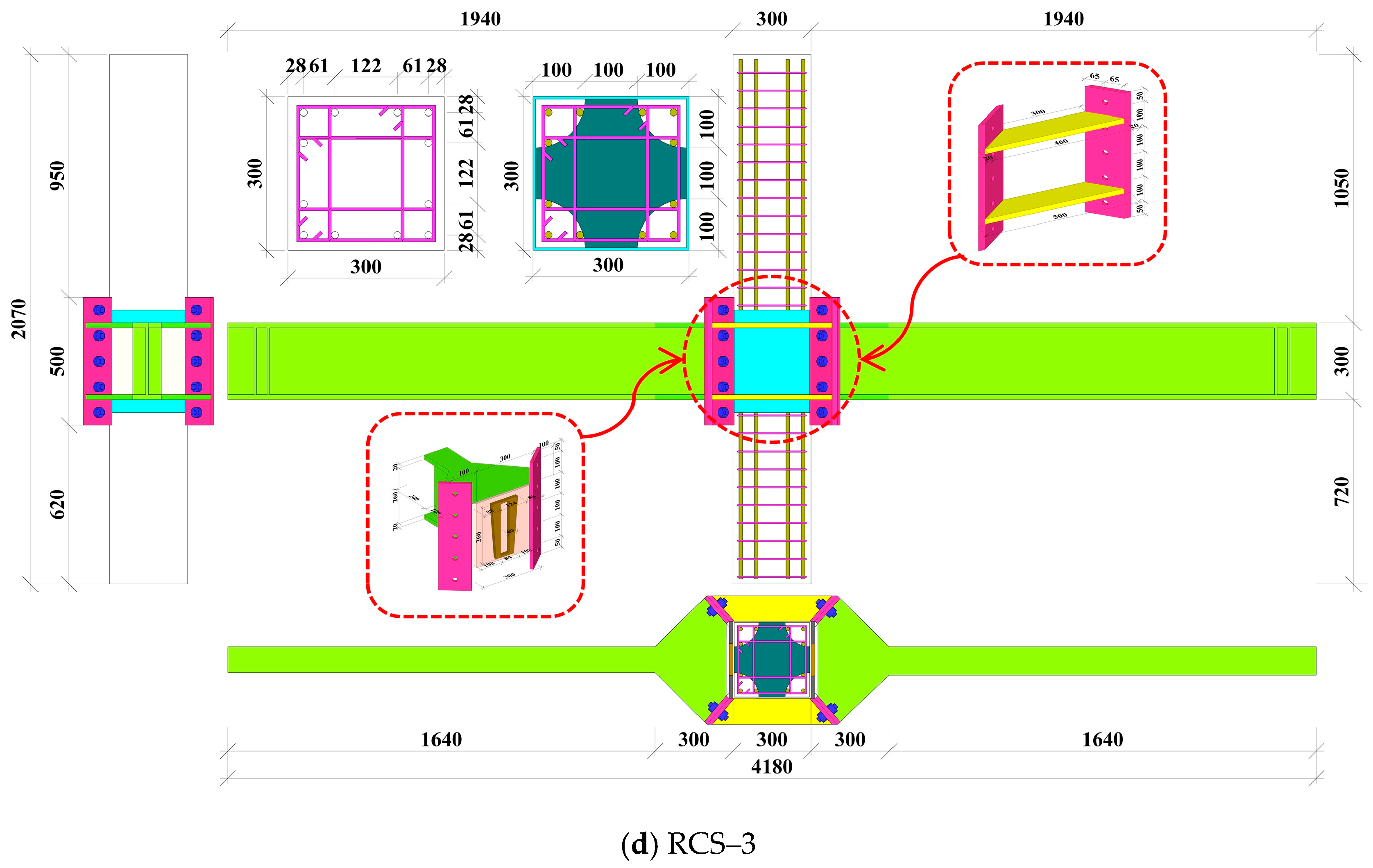
2.1.1. Specimen Specification Preparation

As can be seen in Figure 1, with the specimen RCS-0 as a reference specimen, stiffening the rib via the welding process, with the steel hoop connection fixed, and the steel hoop and concrete column intersection of the core area built-in stiffening plate can improve the joint bending capacity and stiffness. Also, the beam side of the triangular stiffening ribs can improve the welding strength between the steel beam and the steel hoop, as well as the strength of the connection [35], effectively avoiding weld cracks that can result in joint failure. The perforated end plates of specimen RCS-1 were welded with extended flange widening beams and steel beams at the end of the columns, and a wedge-shaped plate was built in between the end plates to transfer the shear force and reduce the difficulty of on-site construction, with the two end plates being related to high-strength bolts. For the study of the performance of extensible end plate-type joints, Özkılıç investigated the cyclic and monotonic performance of the extensible stiffened end plate joints with large-size bolts and thin end plates through experiments and a large number of numerical simulations, with parameters such as different cross-sectional forms, the widths of the end plates, the spacing of the bolt washers, and the thickness of the weld seam being taken into account; the results showed that the current code underestimates the bending load capacity of the extensible stiffened end plate joints [36,37]. Vertically distributed high-strength bolts link the connection component of the specimen RCS-2 to the steel beam. In addition, the upper and lower flanges are connected to the steel beam, which utilizes a groove for assembly, enabling them to transmit bending moment and shear force. To enhance the efficiency of on-site construction joints and facilitate speedy installation, we designed a demountable RCS-3 joint. Figure 1d illustrates the connection structure. It is akin to the demountable RCS-2 joint and makes use of a wedge block to facilitate the transfer of shear force. An external beam and end plate, along with four sets of diagonal bolts, are employed to secure the concrete column and steel beam. This method of joint connection can decrease the necessary quantity of bolts, and the diagonal bolt group can withstand more shear force and the transfer bending moment. Except for the separate energy-absorbing connections installed in the demountable RCS-1, RCS-2, and RCS-3 joints, the material selection and dimensions of all other components remain consistent. These include square-sectioned concrete columns (mm), I-beam steel sections (mm), high-strength grade 8.8 friction bolts with a diameter of 20 mm for longitudinal bars and hoops, longitudinal bars with diameters of 14 mm spaced 61 mm apart, and hoops with diameters of 6 mm spaced 80 mm apart. Technical abbreviations are explained upon first use within the paper.

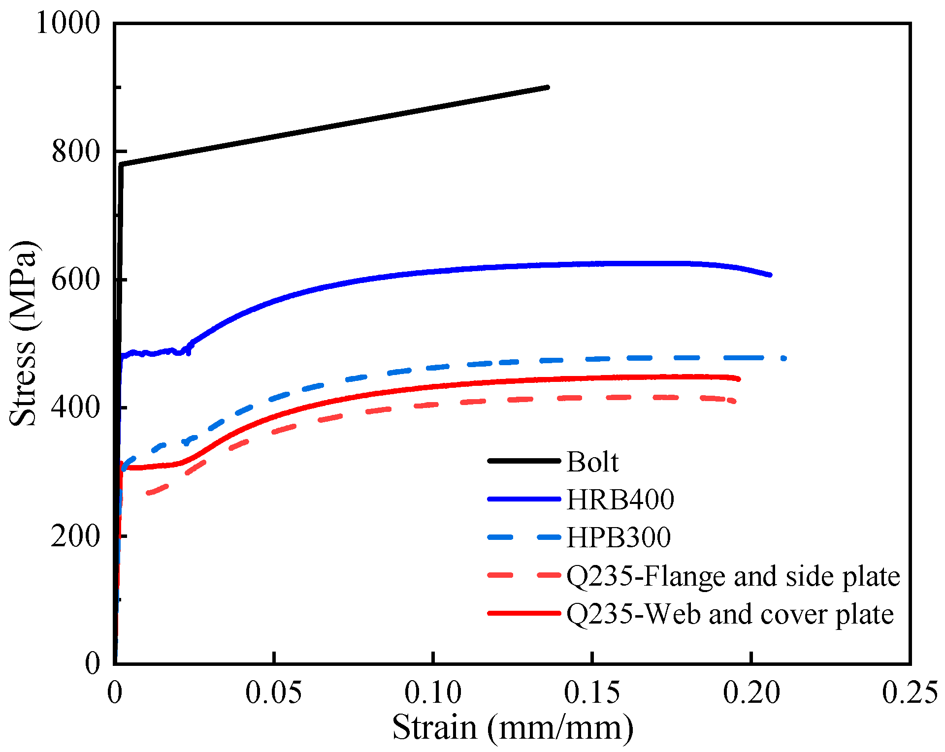
2.1.2. Material Properties

Specimens were prepared using HPB300 steel bars, with a diameter of 6 mm, and HRB400 steel bars, with a diameter of 14 mm. Steel beams were fabricated by welding Q235 steel plates with thicknesses of 10 mm and 20 mm. The material properties of the necessary steel and steel bars were assessed in accordance with the “Metal Materials Tensile Test Part 1: Room Temperature Test Methods” (GB/T 228.1-2010) [38] specifications. Table 1 presents a summary of the mechanical properties of steel, steel bars, and bolts obtained by averaging the test results derived from three material specimens. The concrete columns were mixed in the laboratory with a predetermined mixing ratio and then poured into various forms. P. O 42.5R ordinary Portland cement was utilized, alongside medium sand as fine aggregate and a coarse aggregate that had a particle size range of 5–25 mm. The concrete’s average compressive strength was determined by creating cylindrical specimens that were 300 mm in height and 150 mm in diameter. Subsequently, static load compression strength tests were performed on each group of specimens to acquire the average compressive strength values, which are presented in Table 2.

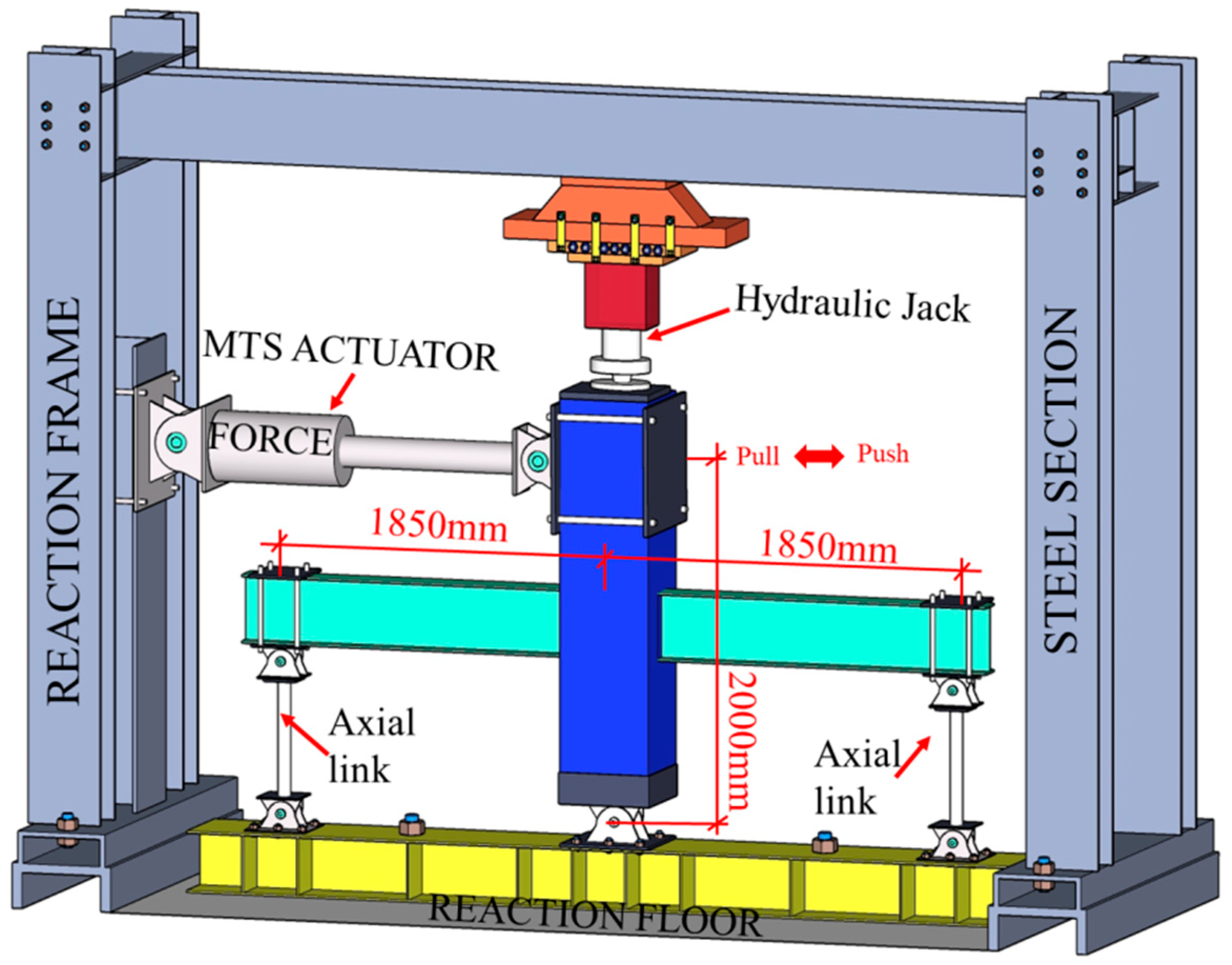
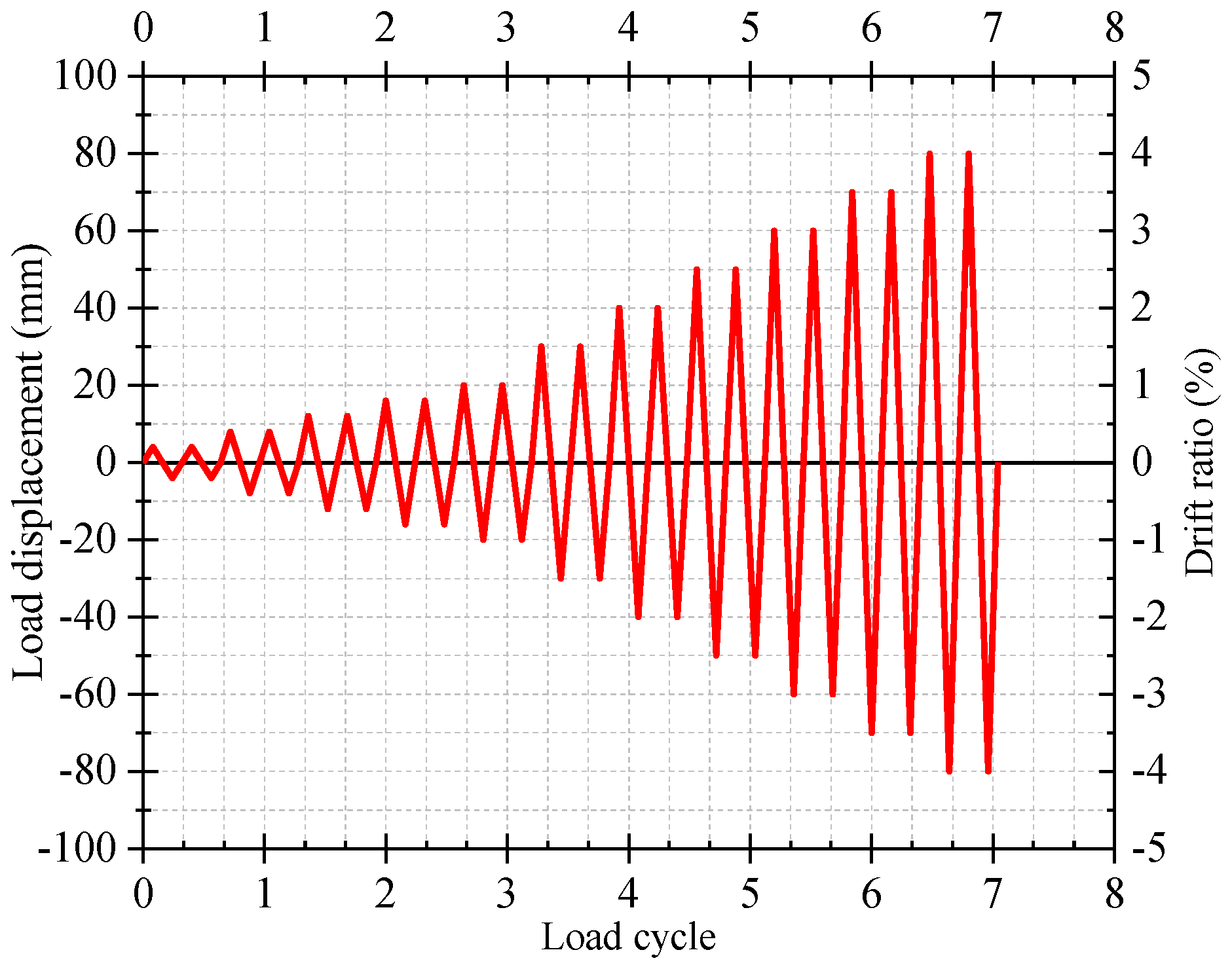
2.2. Test Setup and Loading Condition

The experimental loading apparatus comprises a robust steel framework, a 500 kN MTS hydraulic servo actuator, a vertical hydraulic jack, a firm steel beam, anchor bolts, and auxiliary loading devices such as beam end clamps and column bottom sleeve hinge bearings. Figure 2 shows the complete apparatus. The demountable RCS joint specimen is scheduled for static testing via the application of vertical loads to the column top through hydraulic jacks, controlling the axial stress ratio, followed by horizontal reciprocating loads at the end of the column. The loading protocol for this experiment conforms to the “Code for Seismic Testing Methods of Buildings” (JGJ101-2015) [39], and the loading regime for the planned static testing of the specimen utilizes a full-stage displacement-controlled loading configuration. The loading displacement value is controlled by multiples of the interlayer displacement angle, and each loading is repeated twice. The loading system is depicted in Figure 3. In the later phase of the experiment, it is crucial to remember that loading ceases when the lateral load on the specimen decreases to 85% of the peak load or cannot be sustained any longer.

3. FEM Simulation

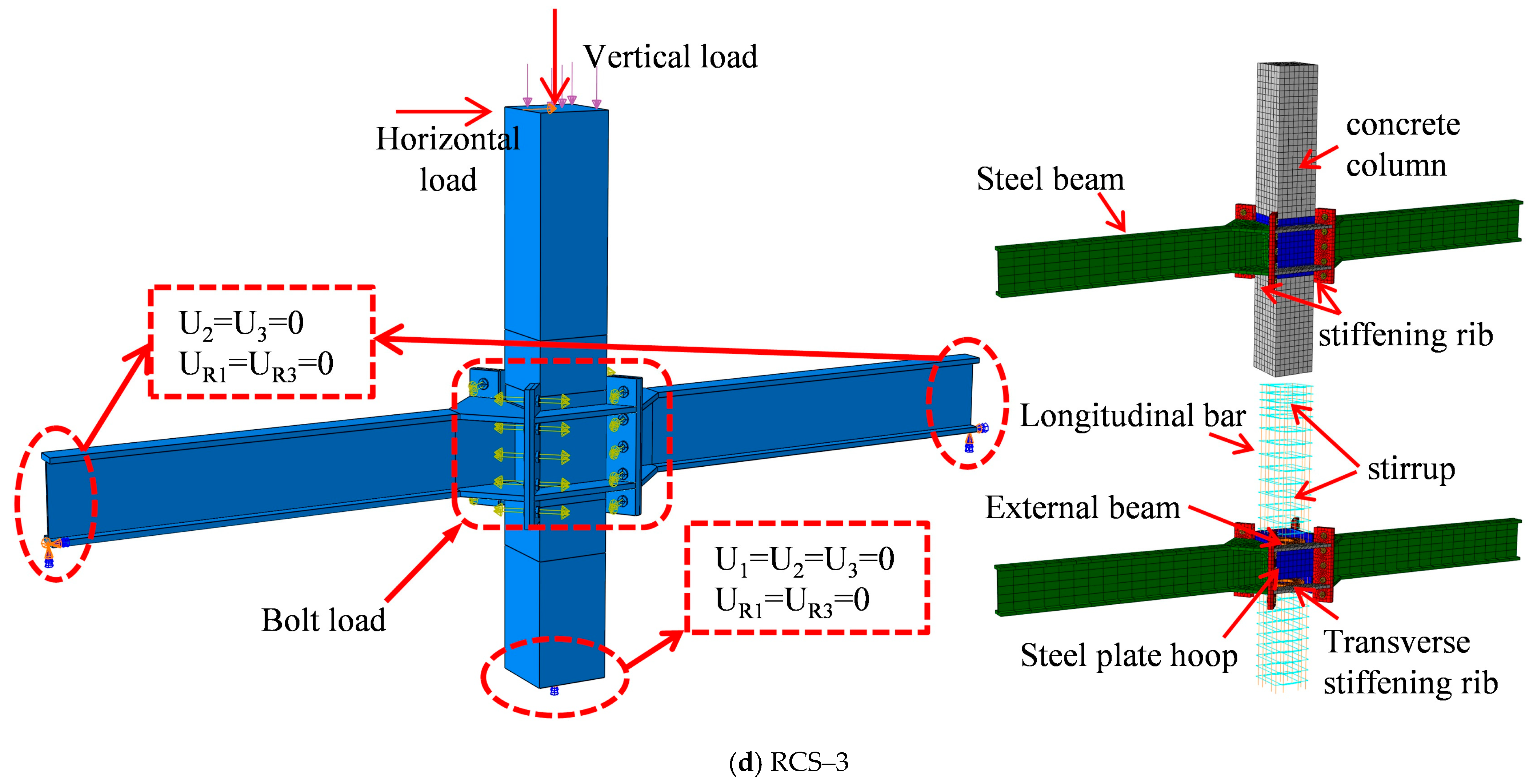
3.1. Model Description

Finite element models of four beam–column joint specimens were established by using the general-purpose finite element software ABAQUS, and the constructional parameters and arrangement diagrams of each specimen are shown in Figure 1. The concrete principal elements entered into the numerical model were calculated according to the tensile–compressive principal relationship criterion in the Code for the Design of Concrete Structures (GB 50010-2010) [40], and the damage parameters were calculated according to the CDP plastic damage model in ABAQUS, in which the damage plasticity model parameters (expansion angle Ψ, eccentricity ε, fb0/fc0, k, and the coefficient of viscosity) were set to 30, 0.1, 1.16, 0.6667, and 0.0001, respectively. The density and Poisson’s ratio of C40 concrete are 2400 kg/m3 and 0.2, respectively, and the isotropic Von Mises’s yield criterion was used to describe the intrinsic behavior of reinforcement bars and steels; the intrinsic stress–strain curves of specific inputs are shown in detail in Figure 4. Furthermore, the intrinsic relationship of bolts was adopted by the bilinear hardening criterion, and the density of steel and Poisson’s ratio were set to 7800 kg/m3 and 0.3, respectively. The concrete columns, steel beams, bolts, and connectors were modeled using C3D8R solid units, while the longitudinal and hoop reinforcement were modeled via T3D2, i.e., three-dimensional two-node frame units.
To replicate the experimental loading process, the control points were linked to the underside of the concrete column and the beam end section, employing the “coupling” function. The displacement and rotational degrees of freedom for the control points, i.e., the six degrees of freedom, were then restricted in the X, Y, and Z planes to ensure comparable boundary conditions to the experimental loading process. The reinforcing steel of the concrete column was incorporated into the corresponding concrete components using the “Embedded Region” instruction to allow the steel and concrete to function together under load and deformation. The “Tie” directive was utilized to limit the welded connections between steel members. Surface-to-surface contact between steel components was established with contact pairs, which included bolt–plate and plate–plate contact. A vertical constant uniformly distributed load of 8 Mpa was applied at the top of the column to meet the 0.2 axial pressure ratio of the experimental frame column. Additionally, a cyclic horizontal load was applied at the column end, as demonstrated in Figure 5.

3.2. Model Validation

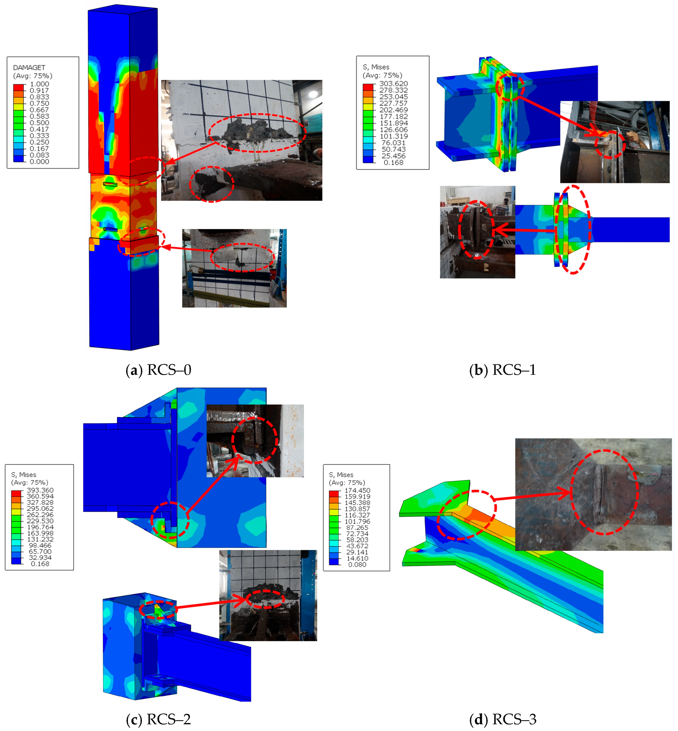
3.2.1. Failure Pattern

During the loading process of the experiment, the four joints exhibited various failure modes. The specimen RCS-0 underwent failure during the second cycle as the loading displacement at the top of the column reached 30 mm. The concrete at the upper and lower joints of the steel plate hoops and the column was crushed, and cracks emerged in the welding seam between the steel beam and the steel plate hoop, signifying a substantial reduction in the lateral bearing capacity of the joint, meaning it is deemed a failure. When the loading displacement at the top of the column reached 50 mm on the second cycle, the external hanging short beam welding seam area of the specimen RCS-1 cracked, and noticeable out-of-plane flexural deformation occurred on the two end boards. As the displacement was further loaded to 80 mm, the welding seam cracks continued to widen, and the horizontal bearing capacity of the joint was less than 85% of the peak load, indicating that the specimen had failed and reached destruction. The steel beam and column of the specimen RCS-2 were fixed using a slot. During testing, audible friction was detected between the end board and slot. The slot connection was responsible for transmitting both bending moment and shear force. Beyond a loading displacement of 40 mm, cracks emerged in the welding seam that joined the slot and cover board. Continuing to load up to 50 mm in the second cycle resulted in the crushing and serious spalling of the upper concrete of the steel plate hoop. Additionally, the welding seam between the slot and the cover board was fractured, which points towards joint failure and destruction. The beam–column connection of the specimen RCS-3 was established by means of an outer ring beam and lateral bolts, accompanied by a wedge plate at the end board to bear a portion of the shear force. When the interlayer displacement reached 50 mm during loading, the joint achieved its highest bearing capacity. As loading continued and reached 60 mm during the second cycle, a fracture became apparent in the welding seam of the left beam flange mutation, leading to the cessation of the loading process and indicating that the specimen had failed.
As demonstrated in Figure 6, a comparison of the failure modes of the experimental specimens and the instantaneous stress distribution of the FEM model suggests that numerical simulation can accurately predict and replicate the ultimate failure states observed in the experiment. These include concrete crushing and spalling, weld fracture, and steel bending deformation. Although there are slight disparities between the numerical and experimental outcomes, the numerical model still satisfies the precision criteria and adequately depicts the stress transfer and mechanical behavior of the joints during the loading process.

3.2.2. The Hysteresis Curves and Skeleton Curves
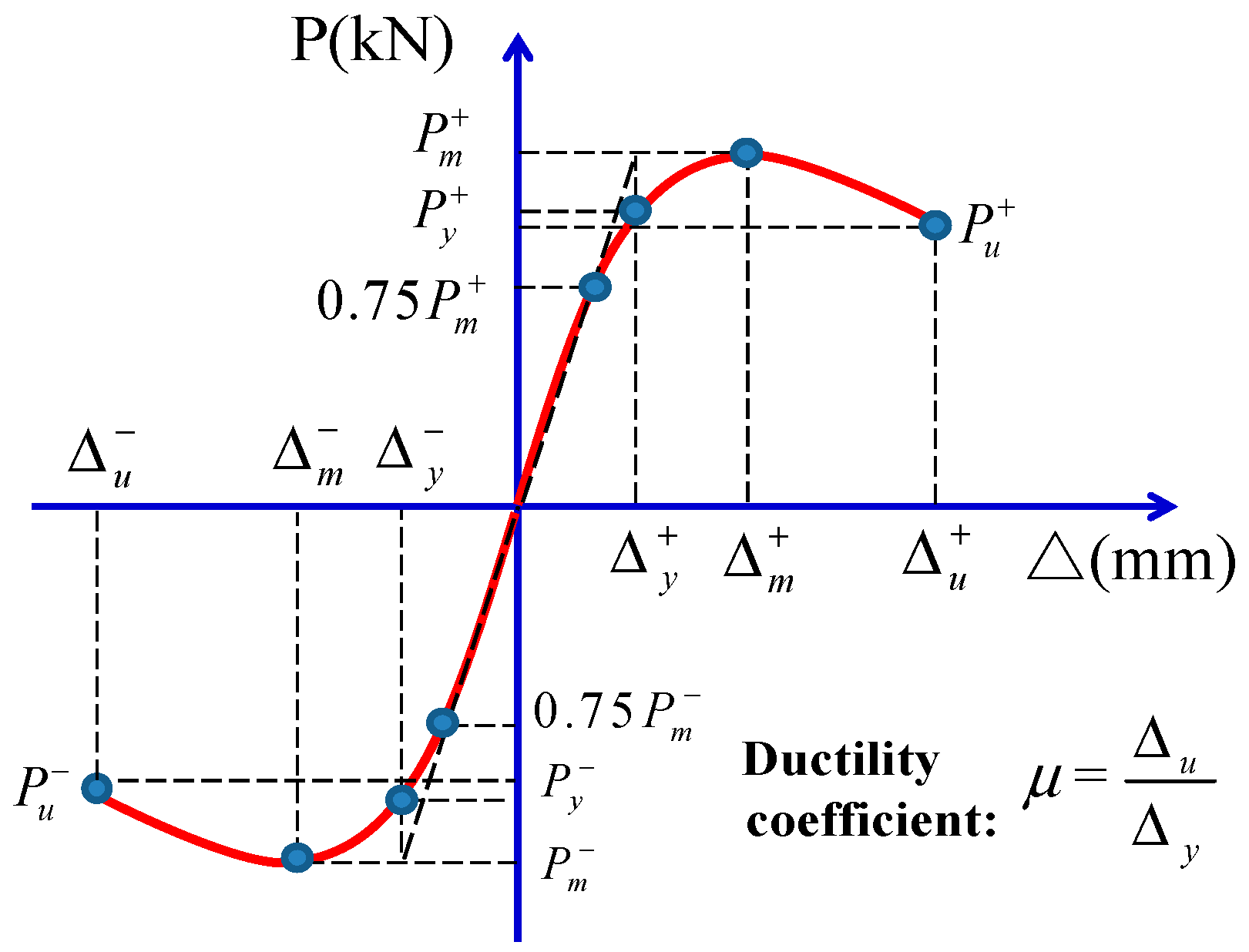
The hysteresis curve and skeleton curve, as obtained via finite element analysis, are presented in Figure 7. The numerical simulation can reasonably predict the overall trend of the hysteresis curves of the four joints in comparison to the experimental findings. However, RCS-1 did not exhibit significant necking effects in the final numerical results. The hysteresis loop envelopes for RCS-2 and RCS-3 are in good agreement, whereas the hysteresis loop envelopes obtained via numerical simulation for RCS-0 and RCS-1 are marginally smaller when compared to the experimental results.
For the non-demountable specimen RCS-0 in the reference group, the negative loading skeleton curve corresponds to the experimental results, whereas the positive loading skeleton curve exceeds the experimental results. This phenomenon could be explained by the initial damage incurred in the positive direction during the experiment. The concrete was tensioned before being pushed, first in the negative direction and then in the positive direction, resulting in a substantially lower positive bearing capacity compared to the negative bearing capacity and numerical findings. On the contrary, regarding the separable specimens RCS-1, RCS-2, and RCS-3 during the initial loading, as well as the elastic and plastic phases, the numerically estimated skeleton curves in the positive and negative directions correspond closely with the experimental outcomes. However, in the numerical simulation, welding is designated as a “tie” connection, and the concrete cannot reach the damaged state of crushing and spalling; hence, the skeleton curve in the numerical simulation does not exhibit a noticeable descending section.

3.2.3. Ductility

As illustrated in Figure 8, the yield point and yield displacement can be determined from the ultimate bearing capacity of the skeleton curve. Table 3 presents the yield load, yield displacement, ultimate load, ultimate displacement, and ductility coefficient for specimens with four joints. From these data, Figure 8 is plotted. The ductility coefficient is defined as the ratio of the beam end displacement at joint failure to the beam end displacement. This can be computed using the formula below:
μ = δ u δ y
From Table 3 to Figure 9, it can be observed that the ductility of the specimens RCS-0 and RCS-3 specimens is poor, as indicated by the finite element results which reveal positive and negative direction ductility coefficients of 2.92 and 3.89 and 2.37 and 2.38, respectively. In contrast, the specimens RCS-1 and RCS-2 exhibited better ductility or deformation capacity, with positive and negative direction ductility coefficients of 4.71 and 5.01 and 6.29 and 6.38, respectively. The ductility coefficients obtained from the finite element analysis exceed the experimental values. The experiment applied negative loading, leading to a build-up of concrete damage in the positive direction. As a result, the positive direction demonstrates a higher level of yield point displacement and lower ductility coefficients than the negative direction.

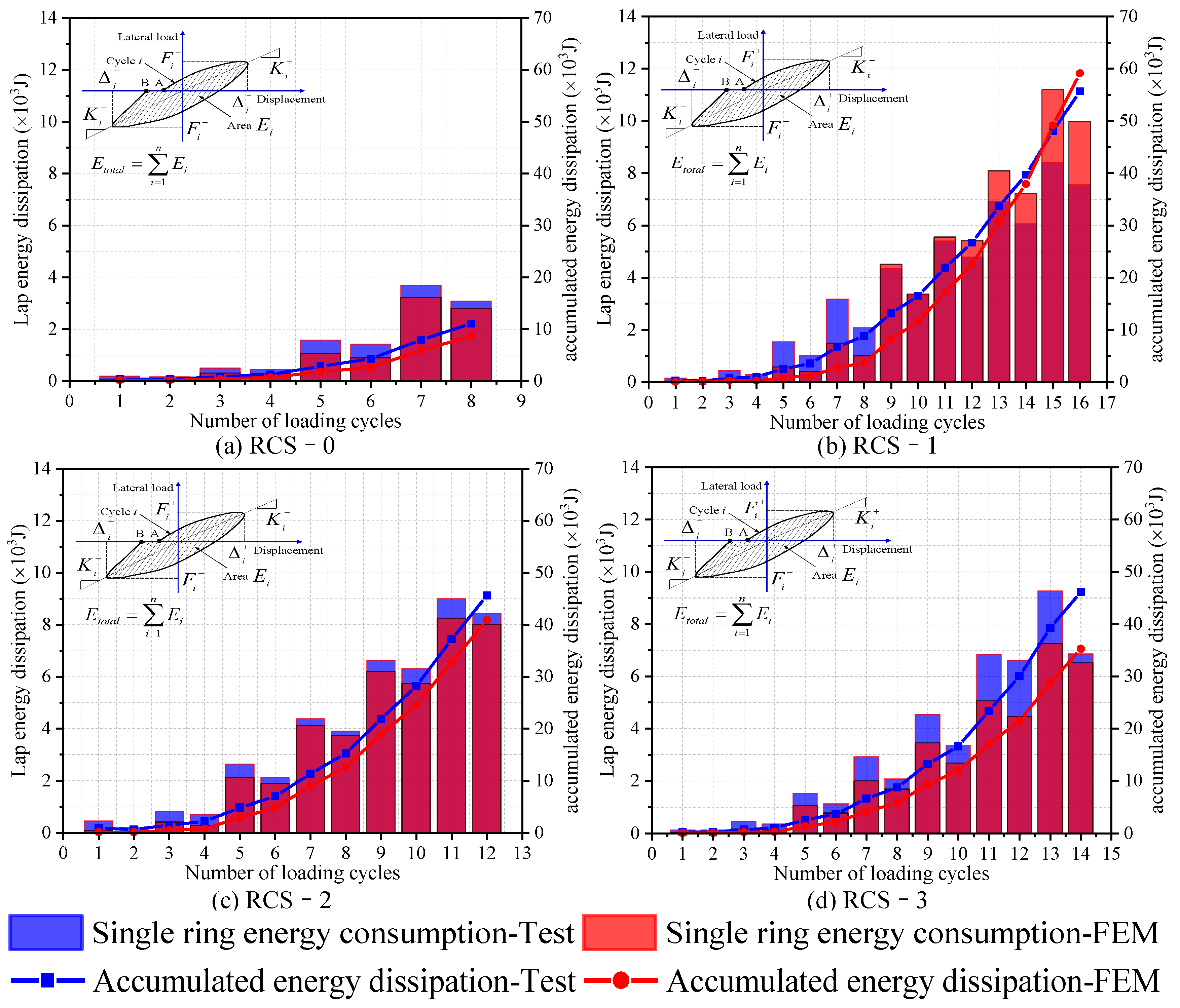
3.2.4. Energy Dissipation

As illustrated in Figure 10, the single-cycle and cumulative energy absorption of each joint are displayed. Upon comparison, it is apparent that the non-demountable specimen RCS-0 exhibits lower single-cycle and cumulative energy absorption at each level of displacement compared to the other three demountable joints. Among them, the cumulative energy absorption of the specimen RCS-1 is the highest, with a 21.97% and 20.57% increase compared to the specimens RCS-2 and RCS-3 in the experimental results. Meanwhile, based on the finite element analysis results, the cumulative energy absorption of the specimen RCS-1 is 44.58% and 67.52% greater than that of the specimens RCS-2 and RCS-3, respectively. Compared to the experimental and finite element analysis outcomes, it is evident that they are in excellent accordance, confirming the precision of the finite element model.

4. FEM Parameter Analysis

4.1. Steel Strength of Some Connector
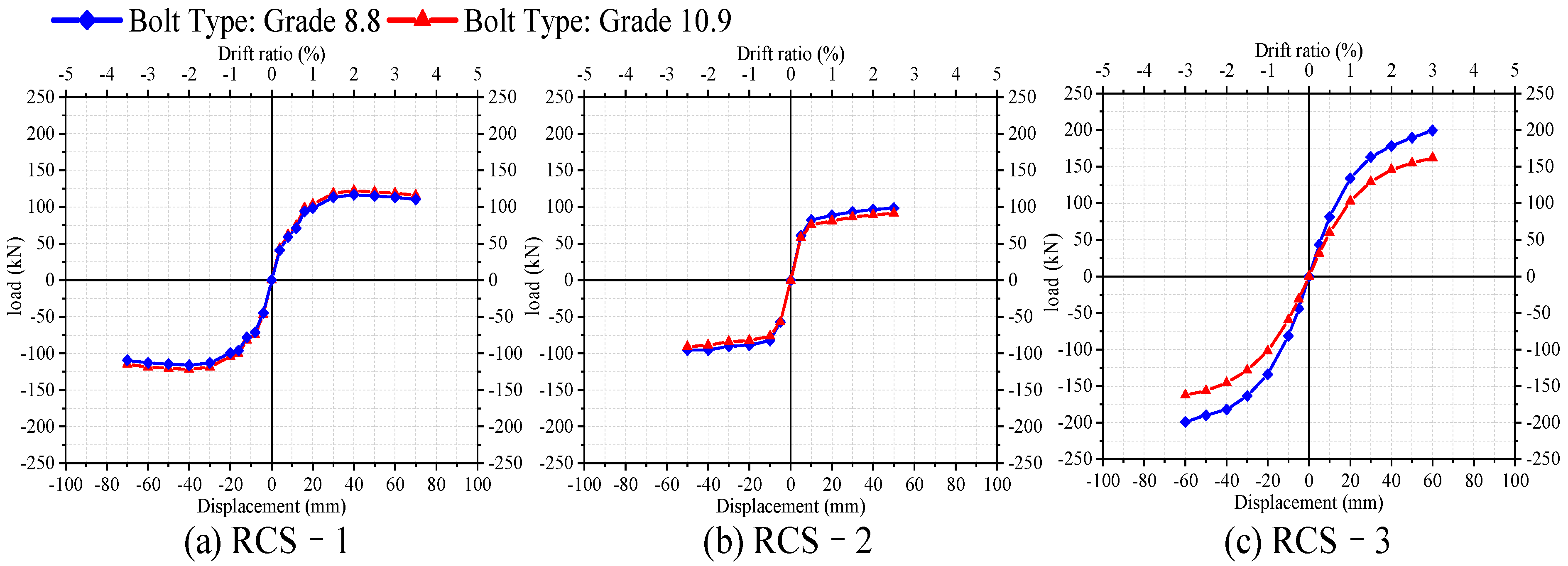
Given the structural variances in the beam–column connections between the three separate RCS joints, this section selects specific connecting components for each joint. One of the analysis parameters is the modification of their steel strength. Figure 11 exhibits the detailed connection components. The validated finite element model permits a comparison of the skeleton curve of the beam–column joint under a reciprocating load. Keeping the dimensions of the specimens and all other conditions unchanged, only the steel grades of the key connecting components in the three demountable joints have been altered from the original Q235 steel to Q345 steel. The finite element analysis obtains the column load–displacement skeleton curves of the three demountable joints under different strength steel connection conditions, as shown in Figure 11.
For the demountable specimens RCS-1 and RCS-3, the strength of the steel connecting elements has no notable impact on the skeleton curve. However, the skeleton curve of the demountable RCS-2 specimen is considerably affected by it. As the specimen RCS-2 depends on its connecting components to transfer both bending moments and shear forces between the beam and column, the vertical high-strength bolts that secure the connecting components to the beam also play a role in bend moment transfer. Thus, strengthening the steel of the connecting components can result in a corresponding increase in bending capacity. Therefore, switching the connecting components from Q235 steel to Q345 steel has no significant impact on the initial stiffness of the joint. However, the ultimate load-bearing capacity rises by 21.00%. Hence, these findings indicate that enhancing the steel strength of the connecting components in the demountable specimen RCS-2 can substantially upgrade the joint’s bearing capacity.

4.2. Bolt Strength

To examine the effect of bolt strength on the seismic behavior of RCS joints, we upgraded the high-strength bolts of the numerical models of the three demountable beam–column joints from grade 8.8 to 10.9. Additionally, the bolts’ pre-tightening force in the finite element model was raised from 120 kN to 150 kN. The skeleton curves for each RCS joint with different bolt types are illustrated in Figure 12. It is evident from the diagram that the bolt type does not have a noteworthy impact on the load-carrying capacity of specimens RCS-1 and RCS-2. In contrast, the demountable RCS-3 joint specimen features a concrete column with a crossbeam that is connected to a steel beam using diagonal bolts. The diagonal bolts are responsible for the primary shear force and bending moment support. As such, improving the strength of the bolts could in turn improve the joint’s ability to withstand horizontal loads.

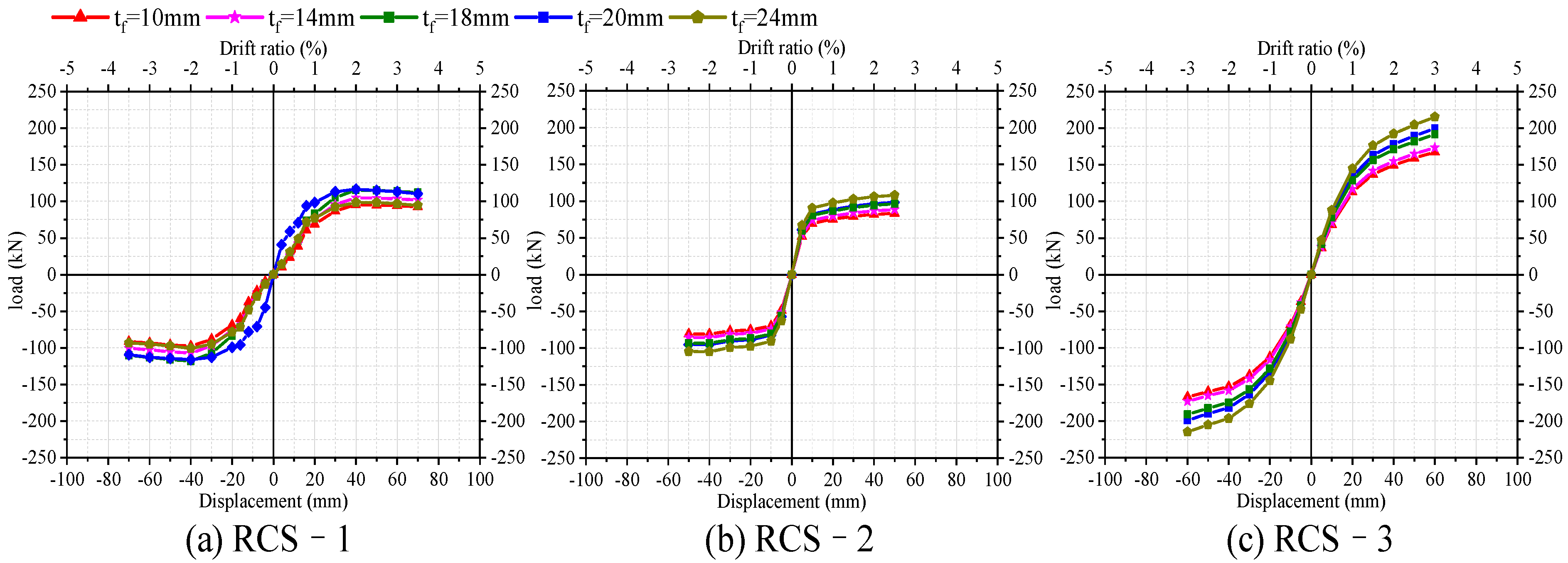
4.3. Steel Beam Flange Thickness

Figure 13 demonstrates the vital impact of flange thickness on the mechanical behavior of the joint. For studying the effect of the flange thickness of pure steel beam segments on the seismic conduct of demountable RCS joints, five finite element models with varying flange thicknesses (tf = 10 mm, 14 mm, 18 mm, 20 mm, 24 mm) were developed. From the skeleton curves acquired via finite element analysis, it is evident that the maximum bearing capacities of the specimens RCS-2 and RCS-3 improves as the flange thickness increases. The bearing capacity increases by 10.02% and 8.24%, respectively, when the flange thickness increases from 10 mm to 24 mm. Concerning the RCS-1 specimen’s skeleton curve, the joint’s bearing capacity exhibits a continually increasing trend with an increase in the flange thickness. However, when the flange thickness continues to increase to 24 mm, the joint’s maximum bearing capacity diminishes. These results indicate that the steel beam design of the specimen RCS-1 is the most suitable, enabling the maximum bearing capacity of the joint.

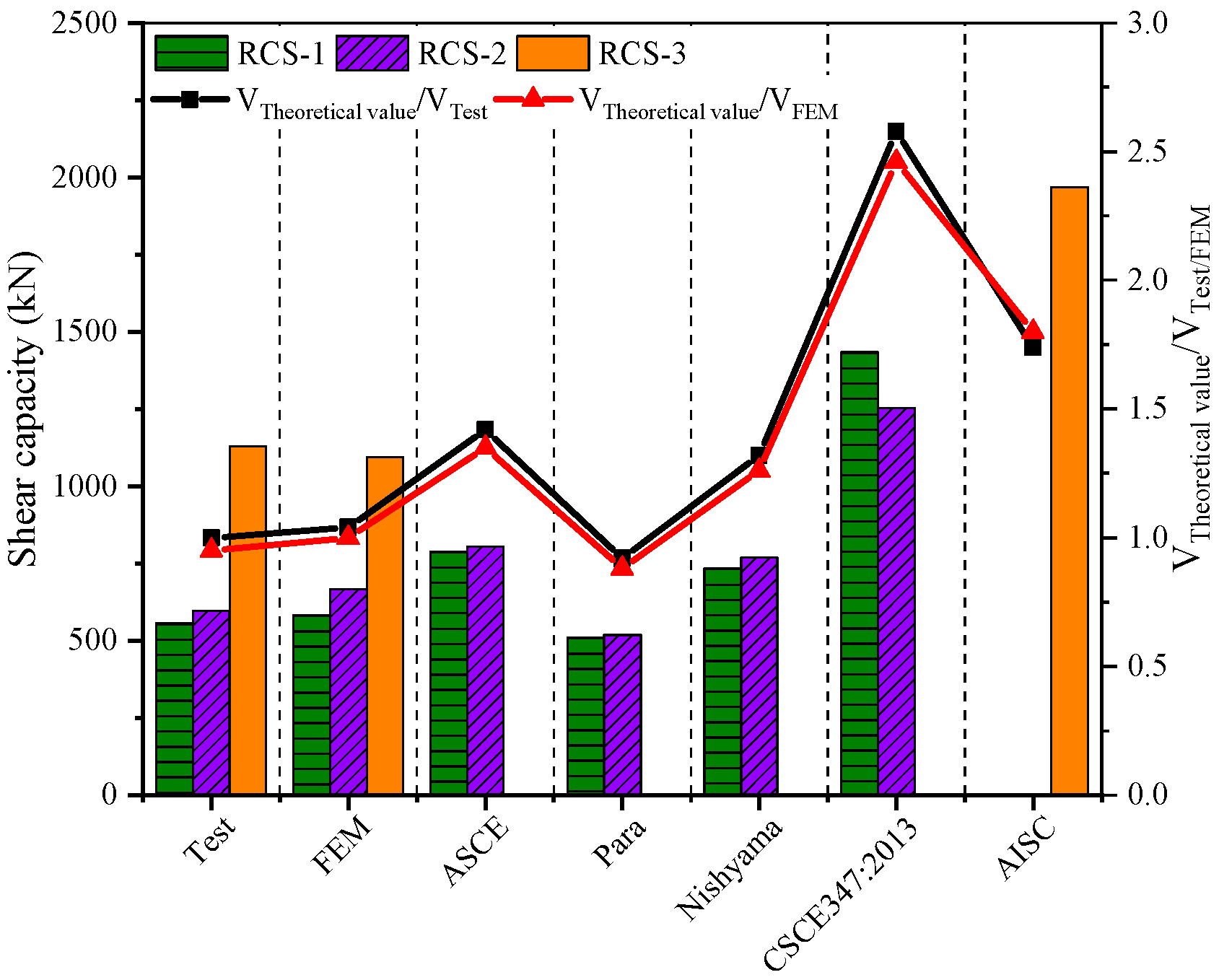
5. Shear Capacity Analysis

This article presents three novel varieties of demountable RCS joints, each designed as a “column through” joint. A steel plate hoop limits the central region of the joint, while transverse reinforcement ribs are mounted inside the transmit stress. The transverse reinforcement ribs significantly enhance the joint’s stiffness. From the failure mode of the specimens, it is apparent that other components fail before the core area of the joint, demonstrating compliance with the design principle of “strong column, weak beam, and strong joint, weak member”.
To investigate a more practical calculation approach for determining the shear-bearing capacity of steel beam-reinforced concrete (RCS) composite joints, Tao et al. [41] compiled shear failure test data of RCS joints from recent years and compared the results with those gained from the Chinese code technique, Nishiyama method, Para method, and ASCE guideline method. The study examined the impact of various parameters on the shear-bearing capacity of the joints. The research findings demonstrate the practical engineering value of all four methods. The Para method exhibits the least dispersion, while the ASCE method is overly conservative with perpendicular beam specimens and displays the greatest dispersion. The Chinese code and Nishiyama method yield similar results; they both indicate a hazardous state for joints where the concrete strength exceeds 60 MPa. The Chinese code offers the most straightforward calculation method. Following the four distinct shear-bearing capacity calculation methods presented in the referenced article, the shear-bearing capacity of each new demountable RCS joint’s core area is computed separately.
According to the ASCE guidelines [42] and the literature [43], it is possible to calculate the ultimate shear strength of the core area of an RCS beam–column joint using the subsequent formula:
V j 0.85 ( 0.85 · γ k 0 f c b 0 h + 0.75 · 1 6 t c p b c p f y c p )
where V j is the shear strength of the beam–column panel region; γ is the strength factor, with internal seams taken as 1.0 and external seams taken as 0.6; k 0 is the restraint strength factor of the external concrete columns, where for joints with tension fasteners and steel straps, it is 2.5, and for other joints, it is 2.0; f c is the standard compressive strength of concrete (MPa); b 0 is the effective joint width; f is the thickness of the cover plate at the beam–column core region; t c p is the width of the cover plate along the shear direction; and f y c p is the standard yield strength of the cover plate.
To compensate for the shortcomings of the ASCE guideline calculation method, Para et al. [44] proposed a method that can be used for the design of “through beam” joints with concrete strengths ranging from 21 MPa to 70 MPa in high-seismic-intensity areas. This method divides the shear capacity of the joint into three parts: steel beam webs and internal and external concrete regions.
V j = 0.9 f w y 3 t w h c + 0.3 f c i b i h c + 0.3 f c o b o h c
f c i = V i b a s e ( 0.0048 f c + 1.13 ) k 1 k 2
f c o = V o b a s e ( 0.0048 f c + 1.13 ) k 1 k 2 k 3
Based on the results of the experimental study, the concrete compressive strength is 48.2 MPa, and the concrete in the core area of the joint is not distinguished between the inner and outer areas. Considering the contribution of the added transverse reinforcement ribs to the shear capacity of the slab area, a modification of the Para method is made, and the formula is as follows:
V j = 1 6 t c p b c p f y c p + 0.3 f c b c h c
f c = V b a s e ( 0.0048 f c + 1.13 ) k 1 k 2 k 3
where b c is the width of the column section; h c is the height of the column section; V b a s e is the basic strength factor, which for RCS joints is approximately twice that of edge joints; and k 1 k 2 k 3 is the concrete restraint factor, which aims to consider the strength enhancement of construction elements such as stirrups, steel hoops, and column surface plates; it requires selecting corresponding values according to different constructions when calculating. For specific details, please refer to Table 1 in reference [44].
Nishiyama et al. [45] provided a design method for the seismic performance of RCS joints in their guidelines for the seismic design of concrete structures. This method applies to concrete strengths ranging from 21 to 60 MPa. Unlike the previous two methods, concrete is no longer divided into inner and outer elements. Instead, the shear strengths of the concrete, beam webs, stirrups, and steel plates on the column surface are directly superimposed. Considering that all the specimens are ‘column-through’ joints, with no steel webs passing through the core area of the slab, the shear capacity of the joint can be calculated using the following formula:
V j = V f + V h + V c
V f = 0.5 A s 1 f s 2 / 3
V r = 1 6 t c p b c p f y c p
V c = 0.04 C 2 C 3 b c h c f c δ
where Vf, Vh, Vc represent the shear load-bearing capacity contributions of the column surface plate, transverse stiffeners, and concrete, respectively; A s 2 is the area of the steel hoops in the shear direction; f s 2 is the design value of the tensile strength of the steel hoops; δ is the influence coefficient of the joint location, where for interior joints, exterior joints, and corner joints, the values are 3, 2, and 1, respectively; and C2, C3 are coefficients related to joint construction, which specifically consider the enhancement effects of extending surface plates, steel hoops, perpendicular beams, etc., on concrete strength. The specific values are shown in Table 2 in reference [45].
China Code CECS347:2013 “Technical Specification for Confining Concrete Column-Composite Beam Frame Structure” [46] proposes two types of joints, beam through and column through, and provides corresponding formulae to calculate the bearing capacity. Like the calculation approach of the Nishiyama method, the shear strength of each component is directly superimposed to obtain the joint capacity. The nodal strength of the column consists of the concrete, hoops, and steel plate of the column surface. However, in the experimental specimens, there are no hoops in the slab area; horizontal reinforcing ribs are used instead. Therefore, the joint shear strength consists of concrete, a column surface steel plate, and horizontal reinforcing ribs:
V i = 0.15 α b c h c f c + 0.4 A s 2 f s 2 + 1 6 t c p b c p f y c p
where α is the joint position influence coefficient; it has a value of 1 for interior joints, 0.7 for exterior joints, and 0.4 for top corner joints. The remaining parameters are referenced above.
Unlike the specimens RCS-1 and RCS-2, the RCS-3 specimens have wedge and corner plates welded to the outer ring of the steel plate hoops. These two detailed components contribute to the shear capacity of the joint. Referring to ANSI/AISC 358-16 [47], the formula for calculating the shear strength is as follows:
V j 0.6 f y c p A p z
A p z = 2 d c t c o l + 4 d l e g C C t l e g C C
where d c is the depth of the concrete column section; t c o l is the thickness of the steel hoop; d l e g C C is the effective depth of the leg components, with a value of d l e g C C = 89 mm; and t l e g C C is the effective thickness of the leg components of the axial ring angle component, with a value of t l e g C C = 13 mm.
Figure 14 and Table 4 show the theoretical shear strength calculation values obtained by four different shear strength methods for three demountable RCS joint specimens. The results show that, compared with the experimental results, except for the Para method which calculates a shear strength lower than the experimental result, the remaining formulae calculate shear strengths higher than the experimental results. This is because the RCS-1 and RCS-2 specimens did not reach yield throughout the loading process of the experiment, resulting in a relatively small contribution to the shear strength. The theoretical calculation formula uses the yield strength of the steel; therefore, the theoretical calculation value is greater than the experimental result. From the data in the table, the finite element analysis of RCS-1 and RCS-2 joint core regions has greater shear strength than the experimental results, while the finite element calculation result of RCS-3 is smaller than the experimental value. Therefore, the ratio of the theoretical calculation result to the finite element result is smaller than the ratio of the theoretical calculation result to the experimental result. Because the Para method does not consider the shear strength of the columnar steel plate, the calculated shear strengths of the specimens RCS-1 and RCS-2 are 8% and 13% less than the experimental results and 12% and 22% less than the FEM predicted values, respectively. The ASCE guide method calculates results that are 42% and 30% higher than the experimental values, which are 35% and 21% higher than the FEM predicted values. The Nishiyama method gives results that are 32% and 29% higher than the experimental values, which are 26% and 15% higher than the FEM predicted values. The calculated value using the national standard CSCE 347:2013 is 158% and 110% higher than the experimental values, which are 146% and 88% higher than the FEM predicted values. This is because the formula recommended in the CSCE standard for calculating the shear strength of the core region of the columnar through the type joint also considers the influence of the end plate bolt connection, resulting in a greatly overestimated shear capacity of the joint. For the specimens RCS-3, the calculated result using the AISC standard is 74% higher than the experimental value and 80% higher than the FEM predicted value. This is because the formula considers the influence of the welding of four corner plates on the side of the steel plate hoop, which improves the calculated value of the shear capacity of the joint core region.

6. Conclusions

This paper proposes three new demountable RCS joints with different connection structures, and cyclic loading tests were conducted to investigate the seismic performance of demountable RCS joints. In addition, three finite element models of the specimens were established, and the accuracy of the finite element models was verified using the experimental results. Then, the influence of different design parameters (strength of the demountable steel connection, type of high-strength bolts, and thickness of the steel flange) on the seismic performance of the joints was analyzed. Based on the experimental and finite element results, the following conclusions are drawn:
(1)
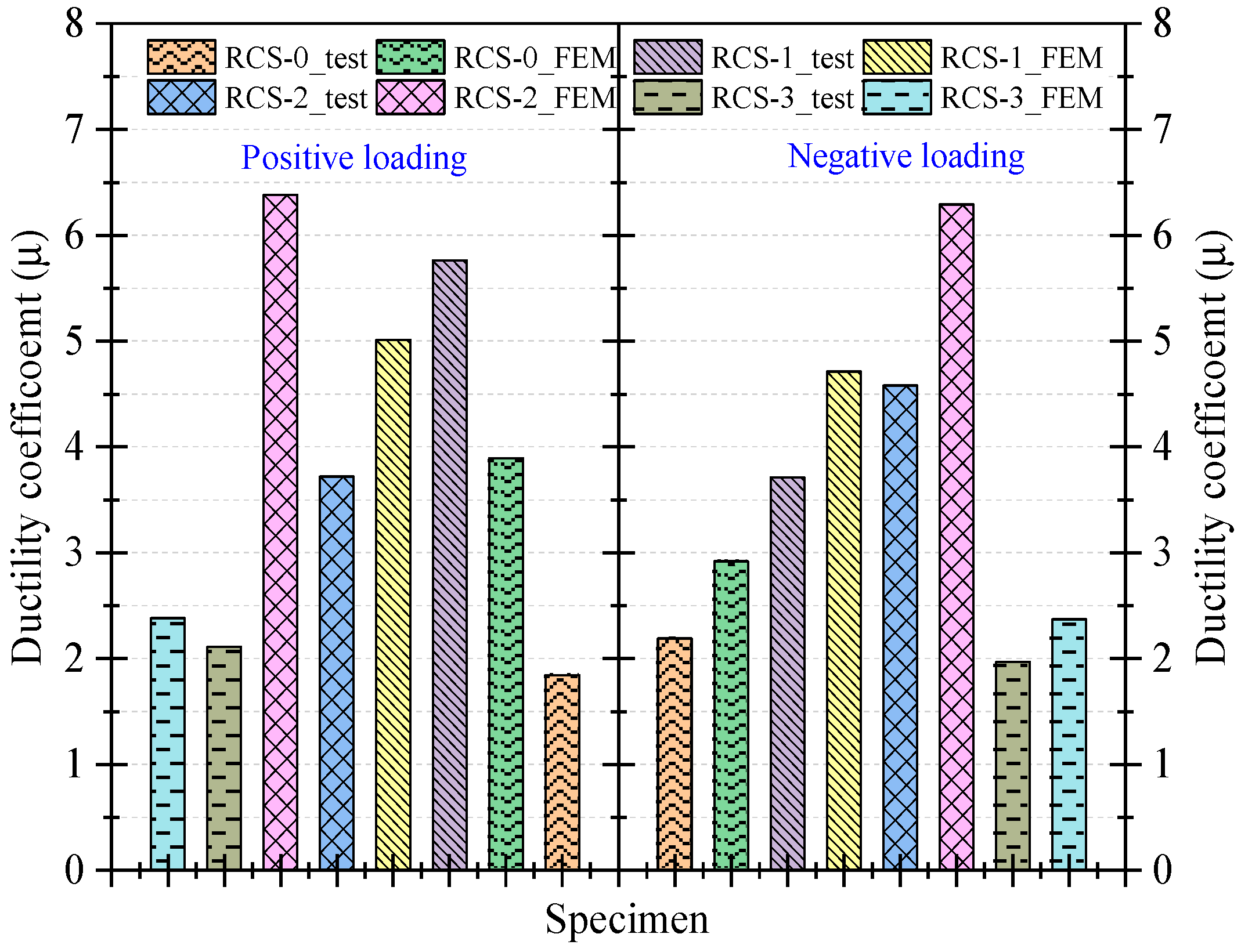
According to the experimental results, the bearing capacity and seismic performance of the three new demountable RCS joints are superior to those of the control group of non-demountable RCS joints. The specimens RCS-1 and RCS-2 have better deformation capabilities than the RCS-0 specimen, with ductility coefficients that are increased by 69% and 109%, respectively, while the difference in the deformation capability between the RCS-3 specimen and the RCS-0 specimen is not significant, with positive and negative loading direction ductility coefficients differing by 14.68% and 10.04%, respectively. The same trend is observed in the energy dissipation capacity of the joints, as the deformability of the joints determines the cumulative energy dissipation of the joints.
(2)
The established finite element model can simulate the performance of non-demountable RCS joints (RCS-0) and demountable RCS joints (RCS-1, RCS-2, and RCS-3) under cyclic loading. The finite element model can effectively reproduce the experimental results and meet the accuracy requirements in terms of joint failure mode, hysteresis behavior, ductility, and energy dissipation.
(3)
The finite element model validated using the experimental results was further analyzed via parameter studies. The results showed that the hysteretic response of demountable joints RCS-1 and RCS-2 is not sensitive to the strength of the detailed connections, while the bolt strength has no significant influence on the hysteretic response of demountable joints RCS-1 and RCS-3.
(4)
The flange thickness of the steel beam has a significant effect on the bearing capacity of the demountable joints. As the flange thickness increases from 10 mm to 24 mm, the ultimate bearing capacity of each joint increases by 9.44%, 10.02%, and 8.24%, respectively. Compared with the skeleton curve, the cross-sectional design of the experimental steel beam is appropriate and can fully exert its flexural bearing capacity.
(5)
This study referred to four different calculation methods recommended in the literature to check whether the shear capacity of the nodal core area met the requirements. By comparing the theoretical calculation results with the experimental and FEM predicted values, it is found that the calculation results for specimens RCS-1 and RCS-2 are higher than the experimental and predicted values because the cylindrical steel plates in these specimens have not yielded. On the other hand, the Para method does not consider the contribution of the cylindrical steel plate to the shear strength of the joint core area, so the calculated result obtained from the formula is underestimated. For the RCS-3 specimen, a four-sided plate is added to the outer ring of the steel plate hoop according to the calculation requirements of ANSI/AISC 358-16, and the calculated shear capacity of the joint core area is overestimated.
(6)
The new demountable RCS joints are not only far superior to ordinary joints in terms of seismic performance, but the application of demountable structures in building construction can also achieve the reuse of building materials and reduce the waste of dismantling, which greatly improves the efficiency of on-site joint construction.
(7)
From the experimental damage pattern, it can be found that all three new demountable RCS joints suffer weld tearing, which fails to provide full play to the flexural load bearing capacity of their connection parts. Therefore, in future work, it would be worthwhile to conduct in-depth research on the analysis of the joint load-carrying mechanism on the basis of ensuring welding quality. The enhancement of the seismic performance of RCS frames using new demountable joints and a nonlinear response under seismic loading will be further investigated in the future.

Author Contributions

Conceptualization, W.L.; methodology, J.C.; software, Z.D. and W.L.; investigation, W.L.; resources, W.L.; data curation, Z.D.; writing—review and editing, J.C.; visualization, W.L.; project administration, W.L. All authors have read and agreed to the published version of the manuscript.

Funding

National Natural Science Foundation of China (NSFC) [Grant No. 51308419]. Zhejiang Province Public Welfare Technology Application Research Project (No. LGF22E080004), and Wenzhou Association for Science and Technology (No. kjfw34).

Informed Consent Statement

Not applicable.

Data Availability Statement

Not applicable.

Conflicts of Interest

The authors declare no conflict of interest.

References

  1. Figueira, D.; Ashour, A.; Yıldırım, G.; Aldemir, A.; Şahmaran, M. Demountable connections of reinforced concrete structures: Review and future developments. Structures 2021, 34, 3028–3039. [Google Scholar] [CrossRef]
  2. Yang, Y.; Chen, B.; Su, Y.; Chen, Q.; Li, Z.; Guo, W.; Wang, H. Concrete mix design for completely recycled fine aggregate by modified packing density method. Materials 2020, 13, 3535. [Google Scholar] [CrossRef] [PubMed]
  3. Yang, Y.; Chen, B.; Zeng, W.; Li, Y.; Chen, Q.; Guo, W.; Wang, H.; Chen, Y. Utilization of completely recycled fine aggregate for preparation of lightweight concrete partition panels. Int. J. Concr. Struct. Mater. 2021, 15, 32. [Google Scholar] [CrossRef]
  4. Uy, B.; Patel, V.; Li, D.; Aslani, F. Behaviour and design of connections for demountable steel and composite structures. Structures 2017, 9, 1–12. [Google Scholar] [CrossRef]
  5. Han, D.; Kalantari, M.; Rajabifard, A. Building information modeling (BIM) for construction and demolition waste management in Australia: A research agenda. Sustainability 2021, 13, 12983. [Google Scholar] [CrossRef]
  6. Van den Berg, M.C. Managing Circular Building Projects. Ph.D. Thesis, University of Twente, Enschede, The Netherlands, 2019. [Google Scholar]
  7. Fayed, S.; Madenci, E.; Özkiliç, Y.O.; Mansour, W. Improving bond performance of ribbed steel bars embedded in recycled aggregate concrete using steel mesh fabric confinement. Constr. Build. Mater. 2023, 369, 130452. [Google Scholar] [CrossRef]
  8. Aksoylu, C.; Özkılıç, Y.O.; Bahrami, A.; Yıldızel, S.A.; Hakeem, I.Y.; Özdöner, N.; Başaran, B.; Karalar, M. Application of Waste Ceramic Powder as a Cement Replacement in Reinforced Concrete Beams toward Sustainable Usage in Construction. Case Stud. Constr. Mater. 2023, 19, e02444. [Google Scholar] [CrossRef]
  9. Rakhshan, K.; Morel, J.C.; Alaka, H.; Charef, R. Components reuse in the building sector—A systematic review. Waste Manag. Res. 2020, 38, 347–370. [Google Scholar] [CrossRef] [PubMed]
  10. Tingley, D.D.; Davison, B. Design for deconstruction and material reuse. Proc. Inst. Civ. Eng.-Energy 2011, 164, 195–204. [Google Scholar] [CrossRef]
  11. Özkılıç, Y.O.; Bozkurt, M.B. Numerical validation on novel replaceable reduced beam section connections for moment-resisting frames. Structures 2023, 50, 63–79. [Google Scholar] [CrossRef]
  12. Özkılıç, Y.O.; Topkaya, C. Extended end-plate connections for replaceable shear links. Eng. Struct. 2021, 240, 112385. [Google Scholar] [CrossRef]
  13. Özkılıç, Y.O.; Bozkurt, M.B.; Topkaya, C. Mid-spliced end-plated replaceable links for eccentrically braced frames. Eng. Struct. 2021, 237, 112225. [Google Scholar] [CrossRef]
  14. Wang, J.; Uy, B.; Thai, H.T.; Li, D. Behaviour and design of demountable beam-to-column composite bolted joints with extended end-plates. J. Constr. Steel Res. 2018, 144, 221–235. [Google Scholar] [CrossRef]
  15. Ataei, A.; Bradford, M.A.; Valipour, H.R. Experimental study of flush end plate beam-to-CFST column composite joints with deconstructable bolted shear connectors. Eng. Struct. 2015, 99, 616–630. [Google Scholar] [CrossRef]
  16. Ataei, A.; Bradford, M.A.; Valipour, H.R.; Liu, X. Experimental study of sustainable high strength steel flush end plate beam-to-column composite joints with deconstructable bolted shear connectors. Eng. Struct. 2016, 123, 124–140. [Google Scholar] [CrossRef]
  17. Lin, X.; Li, H.; He, L.; Zhang, L. Experimental study on seismic behavior of the damage-control steel plate fuses for beam-to-column connection. Eng. Struct. 2022, 270, 114862. [Google Scholar] [CrossRef]
  18. Özkılıç, Y.O. A new replaceable fuse for moment resisting frames: Replaceable bolted reduced beam section connections. Steel Compos. Struct. 2020, 35, 353–370. [Google Scholar]
  19. Peng, L.F. Study on Hysteretic Behavior of a New Prefabricated Concrete Filled Square Steel Column-Steel Beam Joint. Ph.D. Dissertation, Huaqiao University, Quan Zhou, China, 2020. [Google Scholar]
  20. Vasdravellis, G.; Valente, M.; Castiglioni, C.A. Dynamic response of composite frames with different shear connection degree. J. Constr. Steel Res. 2009, 65, 2050–2061. [Google Scholar] [CrossRef]
  21. Valente, M.; Castiglioni, C.A.; Kanyilmaz, A. Dissipative devices for earthquake resistant composite steel structures: Bolted versus welded solution. Bull. Earthq. Eng. 2016, 14, 3613–3639. [Google Scholar] [CrossRef]
  22. Xiao, J.; Ding, T.; Zhang, Q. Structural behavior of a new moment-resisting DfD concrete connection. Eng. Struct. 2017, 132, 1–13. [Google Scholar] [CrossRef]
  23. Ding, T.; Xiao, J.; Chen, E.; Khan, A.U.R. Experimental study of the seismic performance of concrete beam-column frame joints with DfD connections. J. Struct. Eng. 2020, 146, 04020036. [Google Scholar] [CrossRef]
  24. Huang, W.; Hu, G.; Miao, X.; Fan, Z. Seismic performance analysis of a novel demountable precast concrete beam-column connection with multi-slit devices. J. Build. Eng. 2021, 44, 102663. [Google Scholar] [CrossRef]
  25. Wang, W.; Zhang, X.D.; Chen, J.; Zhou, X.L.; Zhang, B. Repetitive behavior of an advanced demountable bolted shear connection in push-off tests. Constr. Build. Mater. 2023, 362, 129656. [Google Scholar] [CrossRef]
  26. Malla, P.; Xiong, F.; Cai, G.; Xu, Y.; Larbi, A.S.; Chen, W. Numerical study on the behaviour of vertical bolted joints for precast concrete wall-based low-rise buildings. J. Build. Eng. 2021, 33, 101529. [Google Scholar] [CrossRef]
  27. He, J.; Suwaed, A.S.H.; Vasdravellis, G.; Wang, S. Behaviour and design of the ‘lockbolt’ demountable shear connector for sustainable steel-concrete structures. Structures 2022, 44, 988–1010. [Google Scholar] [CrossRef]
  28. Loqman, N.; Safiee, N.A.; Bakar, N.A.; Nasir, N.A.M. Structural behavior of steel-concrete composite beam using bolted shear connectors: A review. MATEC Web Conf. 2018, 203, 06010. [Google Scholar] [CrossRef]
  29. Cheng, C.T.; Chen, C.C. Seismic behavior of steel beam and reinforced concrete column connections. J. Constr. Steel Res. 2005, 61, 587–606. [Google Scholar] [CrossRef]
  30. Dung Le, D.; Nguyen, X.H.; Nguyen, Q.H. Cyclic testing of a composite joint between a reinforced concrete column and a steel beam. Appl. Sci. 2020, 10, 2385. [Google Scholar] [CrossRef]
  31. Zhang, J.; Hu, X.; Gong, S.; Wu, J.; Zhu, W.; Ren, C. Experimental investigation of steel-concrete composite beam to reinforced-concrete column joints with single plate shear connection. Eng. Struct. 2021, 245, 112906. [Google Scholar] [CrossRef]
  32. Fargier-Gabaldón, L.B.; Parra-Montesinos, G.J.; Wight, J.K. Seismic Behavior of Exterior Reinforced Concrete Wide-Column-to-Steel Beam Joints. ACI Struct. J. 2020, 117, 117–128. [Google Scholar]
  33. Men, J.; Xiong, L.; Wang, J.; Fan, G. Effect of different RC slab widths on the behavior of reinforced concrete column and steel beam-slab subassemblies. Eng. Struct. 2021, 229, 111639. [Google Scholar] [CrossRef]
  34. GB 50011-2010; National Standard of the People’s Republic of China. Code for Seismic Design of Buildings. China Construction Industry Press: Beijing, China, 2010.
  35. Ozkilic, Y.O. The effects of stiffener configuration on stiffened T-stubs. Steel Compos. Struct. 2022, 44, 475–488. [Google Scholar]
  36. Özkılıç, Y.O. Cyclic and monotonic performance of unstiffened extended end-plate connections having thin end-plates and large-bolts. Eng. Struct. 2023, 281, 115794. [Google Scholar] [CrossRef]
  37. Özkılıç, Y.O. Cyclic and monotonic performance of stiffened extended end-plate connections with large-sized bolts and thin end-plates. Bull. Earthq. Eng. 2022, 20, 7441–7475. [Google Scholar] [CrossRef]
  38. GB/T 228.1-2010; National Standard of the People’s Republic of China. Tensile Testing of Metallic Materials Part I: Room Temperature Test Methods. China Construction Industry Press: Beijing, China, 2010.
  39. JGJ/T 101-2015; National Standard of the People’s Republic of China. Specification for Seismic Testing of Buildings. China Construction Industry Press: Beijing, China, 2015.
  40. GB 50010-2010; National Standard of the People’s Republic of China. Design Code for Concrete Structures. China Construction Industry Press: Beijing, China, 2010.
  41. Tao, Y.; Xiao, Z.; Zhao, W. Comparative study on calculation methods of shear capacity of RCS hybrid joints. J. Harbin Inst. Technol. 2022, 1–16. [Google Scholar]
  42. Cordova, P. Validation of the Seismic Performance of Composite RCS Frames: Full-Scale Testing Analysis and Seismic Design. Ph.D. Dissertation, Stanford University, Stanford, CA, USA, 2005. [Google Scholar]
  43. Ma, H.W. Study on the Joints of Composite Beam and Continuous Compound Spiral Hoop Reinforced Concrete Column. Ph.D. Dissertation, Xi’an University of Architecture and Technology, Xi’an, China, 2003. (In Chinese). [Google Scholar]
  44. Parra-Montesinos, G.; Wight, J.K. Modeling shear behavior of hybrid RCS beam-column connections. J. Struct. Eng. 2001, 127, 3–11. [Google Scholar] [CrossRef]
  45. Nishiyama, I.; Kuramoto, H.; Noguchi, H. Guidelines: Seismic design of composite reinforced concrete and steel buildings. J. Struct. Eng. 2004, 130, 336–342. [Google Scholar] [CrossRef]
  46. CECS 347-2013; National Standard of the People’s Republic of China. Technical Specification for Constrained Concrete Column Combined Beam Frame Structures. China Construction Industry Press: Beijing, China, 2013.
  47. ANSI/AISC 358-16; Prequalified Connections for Special and Intermediate Steel Moment Frames for Seismic Applications. AISC: Chicago, IL, USA, 2016.
Figure 1. Demountable beam–column joints in the whole and connecting component diagram.
Buildings 13 02558 g001aBuildings 13 02558 g001bBuildings 13 02558 g001c
Figure 2. Laboratory specimen loading device.
Buildings 13 02558 g002
Figure 3. Loading system.
Buildings 13 02558 g003
Figure 4. Stress–strain curves of the bolts, reinforcement, and steel.
Buildings 13 02558 g004
Figure 5. Boundary conditions and meshing of finite element model.
Buildings 13 02558 g005aBuildings 13 02558 g005bBuildings 13 02558 g005c
Figure 6. Comparison of stress distribution between test and finite element results.
Buildings 13 02558 g006
Figure 7. Comparison of hysteresis curve and skeleton curve between finite element simulation and test results.
Buildings 13 02558 g007
Figure 8. Ductility coefficient calculation diagram.
Buildings 13 02558 g008
Figure 9. Ductility coefficient of each joint specimen.
Buildings 13 02558 g009
Figure 10. Single-ring energy dissipation and cumulative energy dissipation of each joint specimen.
Buildings 13 02558 g010
Figure 11. Effect of connector steel strength on the bearing capacity of demountable joint specimens.
Buildings 13 02558 g011
Figure 12. Effect of bolt type on the bearing capacity of demountable joint specimens.
Buildings 13 02558 g012
Figure 13. Effect of steel beam flange thickness on the bearing capacity of demountable joint specimens.
Buildings 13 02558 g013
Figure 14. Comparison of shear strength of demountable RCS joints for different methods.
Buildings 13 02558 g014
Table 1. Material properties of steel, rebar, and bolts.
GradeSampling Position E s /GPa f y / M P a ε y f u / M P a ε u
Q235Web and cover plate198308.30.00206450.50.1598
Flange and side plate205254.50.00217423.20.1612
HRB400Longitudinal bar196479.30.00213631.20.1532
HPB300Stirrup201342.70.00221487.60.1956
8.8Bolts2007800.002029000.1360
Table 2. Average compressive strength of concrete cylinder test block.
Specimen IDRCS-0RCS-1RCS-2RCS-3
Average compressive strength (MPa)38.5042.5230.9539.24
Table 3. Yield load, ultimate load, and ductility factor.
Specimen IDLoad DirectionYield Load
p y / k N
Yield Displacement
y / m m
Peak Load
u / k N
Peak Displacement
p u / m m
Ductility Coefficient
μ
TestRCS-0Negative−94.20−16.28−125.6−30.001.84
Positive52.3113.6869.7530.002.19
RCS-1Negative−74.00−12.15−98.66−70.005.76
Positive83.9311.67111.943.293.71
RCS-2Negative−65.64−13.44−87.52−50.003.72
Positive65.7610.9287.6850.004.58
RCS-3Negative−159.00−28.37−212−60.002.11
Positive139.3630.46185.8160.001.97
FEMRCS-0Negative−94.23−7.71−125.64−30.003.89
Positive88.5810.29118.1030.002.92
RCS-1Negative−87.04−13.98−116.06−70.005.01
Positive87.2314.86116.3170.004.71
RCS-2Negative−71.64−7.84−95.52−50.006.38
Positive73.647.9595.1950.006.29
RCS-3Negative−149.30−25.22−199.06−60.002.38
Positive149.5125.31199.3460.002.37
Table 4. Comparison of shear strength of demountable RCS joints (kN).
Joint TypesRCS-1RCS-2RCS-3
Test values555.48596.211128.32
FEM583.25667.761094.47
ASCE788.78804.88-
V J A S C E / V J t e s t 1.421.30
V J A S C E / V J F E M 1.351.21
Para 511.04518.70
V J P a r a / V J t e s t 0.920.87
V J P a r a / V J F E M 0.880.78
N i s h i y a m a 733.23769.11
V J N i s h i y a m a / V J t e s t 1.321.29
V J N i s h i y a m a / V J F E M 1.261.15
CSCE 347:2013 1433.291254.84
V J C E C S / V J t e s t 2.582.10
V J C E C S / V J F E M 2.461.88
AISC - 1967.88
V J A I S C / V J t e s t 1.74
V J A I S C / V J F E M 1.80
Disclaimer/Publisher’s Note: The statements, opinions and data contained in all publications are solely those of the individual author(s) and contributor(s) and not of MDPI and/or the editor(s). MDPI and/or the editor(s) disclaim responsibility for any injury to people or property resulting from any ideas, methods, instructions or products referred to in the content.

