Article

Experimental Vibration Analysis in the Knowledge Process of a Historic Confined Masonry Building

1
Italian National Agency for New Technologies, Energy and Sustainable Economic Development, Bologna Research Centre, 40129 Bologna, Italy
2
Italian National Agency for New Technologies, Energy and Sustainable Economic Development, Casaccia Research Centre, 00123 Rome, Italy
*
Author to whom correspondence should be addressed.
Buildings 2023, 13(10), 2560; https://doi.org/10.3390/buildings13102560
Submission received: 10 September 2023 / Revised: 3 October 2023 / Accepted: 6 October 2023 / Published: 10 October 2023

Abstract

:
Experimental vibrational analysis is used in the knowledge process of a historic building, made of confined masonry, a construction system suggested in the reconstruction after the 1915 earthquake at Avezzano, Italy. The building was the primary subject of the usual experimental campaign to verify the structural geometry, the characteristics of the materials and the permanent loads. Then, a detailed experimental vibration analysis was carried out. Data were analysed both in the frequency and in the time domains. This combined approach allowed us to point out the importance of the floor deformability on the dynamic behaviour of the structure. A finite element model was set up using the equivalent frame method and calibrated on the basis of the experimental vibrational analysis results. The constitutive law of the confined masonry was fine-tuned, following the literature and present standard suggestions. The pushover analyses allowed us to uncover the behaviour factor of the structure and the seismic safety index, which was found to be quite low and very similar to that obtained via a response spectrum analysis.

1. Introduction

The knowledge of static and dynamic properties is essential to understand the structural behaviour of complex buildings or buildings whose materials have mechanical characteristics that are difficult to evaluate. Knowledge makes it possible to develop reliable models, calibrated on the real response, which can be used to evaluate behavioural scenarios that are also in the presence of different types of actions. Obviously, the experimental data are not easy to interpret, especially for the complex buildings mentioned above, such as the historical masonry ones. Moreover, the application of monitoring techniques to the field of cultural heritage is challenging due to the need of respecting its architectural and historical value [1]. However, all this information is essential for a correct assessment of the structural health status of a building and the definition of an effective retrofit intervention. You cannot decide how to intervene if you do not know the structure very well.
Experimental vibration analysis is undoubtedly a technique to use to understand the behaviour of a structure in a seismic area. It is cheap, minimally invasive, fast and reliable. It is useful for finding out the actual vibration modes to consider in a dynamic response spectrum analysis or for establishing the most appropriate force system in a push-over analysis. Recently, the application of wireless sensor networks (WSNs) as a new kind of monitoring system architecture, flexible and with minor costs, has been explored [2].
The convenience is, above all, in the exploitation of the environmental vibrations to excite the structure. These are present everywhere at no cost and, in general, offer a natural excitation with a broad spectrum in frequency. The downside is that they have low energy. Therefore, they almost never succeed in triggering a non-linear response. On the other hand, for the same reason, they provide useful indications of the dynamic behaviour at the onset of motion and can allow for the identification of the most vulnerable elements of a building, whereby the first exceeding instances of the elastic limits presumably occur.
The analysis of the obtained recordings can be performed in the time domain and/or in the frequency domain. The study in the frequency domain is usually carried out by analysing the auto-spectra of the recordings obtained at various locations on the structure and the cross-spectra of significant pairs of the recordings themselves and allows for identifying the resonance frequencies and the mode shapes, obviously in the case of linear behaviour. The analysis in the time domain makes it possible to identify the maximum values of the vibration amplitudes and also to have an immediate vision of the prevailing movement of the structure, if any.
Relevant previous applications concerned structures of historical and artistic interest. Among these, the Coclid columns [3,4], the Colosseum [5] and the Egyptian obelisks in Rome [6]. In the first case, the synergistic use of the analysis in the time and frequency domains allowed for the highlighting of peculiar aspects of the behaviour of each column. In the second one, the study was conducted by considering multiple configurations for the sensors and reconstructing the movement in the space of the remaining portion of the north wall. In the third case, an accurate analysis of the materials was carried out in parallel with the dynamic analysis, through non-destructive tests, and was able to develop an effective numerical finite elements model. Recently, particular attention has been paid to the possibility of using historical structures to host social events, such as pop music concerts [7].
The long-term monitoring allowed for the underscoring of the environmental parameters’ influence (particularly thermal variations) on the modal characteristics of ancient masonry constructions [8]. Environmental conditions evolving over time can hide variations in the dynamic properties due to structural damaging, leading to an incorrect health status assessment. For this reason, the influence of environmental conditions on modal parameters has to be quantified and eliminated [9].
Among the tower structures, the San Frediano bell tower in Lucca (Italy) was instrumented along its height with triaxial seismometric stations for about one year, and the dependence of the tower’s frequencies on the ambient temperature was investigated [10]. Correlation studies between modal frequencies and temperature were the result of a one-year dynamic monitoring performed on the tower of the historic complex of “Santa Maria del Carrobiolo” in Monza (Italy) [11]. The feasibility of damage detection methods based on natural frequency shifts was demonstrated through the 15-month dynamic monitoring of the tallest historic tower in Mantua (Italy) by means of low-cost monitoring systems (consisting of a few accelerometers and temperature sensors) [12].
The environmental effects on the dynamic response were investigated also with reference to two complex case studies of the modal and structural identification of monuments in Portugal: the Clock Tower of Mogadouro and the Church of Jerónimos Monastery in Lisbon, monitored by University of Minho through vibration, temperature and relative air humidity sensors [13].
It must also be considered that the phenomenon of Soil Structure Interaction (SSI), acting on the static and dynamic response of buildings, can affect the dynamic identification process. The issue was addressed by considering the bell tower of Santa Sofia in Benevento (Italy), as a case study which attempted to unravel the influence of the ground on the structural response [14].
A large number of case studies in Italy are reported in [15]. The viability of ambient vibration testing for complex masonry structures is demonstrated in [16] for the relevant case study of the Sanctuary of Vicoforte (Italy). Finally, in [17], a collection of interesting works on the subject is presented.
Experimental tests on shaking tables are useful when the aim of the study is to analyse the response of the structure under established inputs. In [18], interesting applications on models of masonry buildings before and after the retrofit intervention are shown. Shaking table tests were also used for damage detection via a modal analysis of confined masonry structures [19].
Furthermore, a recent study has highlighted the structural behaviour of a masonry building, subject to a push-over performed in reality, i.e., an experimental push-over [20].
Previous experiences in the field of buildings have also pointed out the difficulty in interpreting experimental data, but above all, the difficulty lies in structural modelling [21], especially when the structure is significantly damaged [22]. In some cases, the modulus of elasticity of the masonry was adjusted so that the numerical model achieved the experimental results [23]. In other cases, vibration measurements were used for the numerical model calibration of a multi-leaf stone masonry wall [24] or to validate the rigid diaphragm assumption in the seismic assessment [25]. Moreover, the tuning of the numerical model can include, as calibration parameters, boundary conditions in addition to mechanical quantities [2].
Also the choice of the modelling method is relevant. In fact, besides the Finite Element Method (FEM), the Discrete Element Method (DEM) proved to be particularly successful in analysing masonry structures. This discontinuous approach, where the masonry is represented as a system of interacting distinct blocks, is especially suited when the interest is in the prediction of collapse mechanisms. A method for simulating the seismic response of masonry structures based on DEM, taking into account for sliding, separation and impact among blocks, is proposed in [26]. In [27], a review of the main models based on DEM and related numerical techniques is presented, whereas in [28], DEM is implemented to capture all commonly noted failure mechanisms through a novel computational modelling strategy. Recently, an interesting application of DEM for structural collapse simulation, with as case study on the Great Wall of China, was published [29].
In [30,31], the general principles for the correct use of the experimental vibrational analysis were analysed, while in [32], an analytical comparison between techniques for the identification of modal properties through ambient vibrations was performed. As far as the issues faced by the authors of [33], the aim was to check if the dynamic identification procedures, usually applied to reinforced concrete or steel buildings, could provide useful information in the estimation of the dynamic characteristics of existing masonry buildings as well. In [34], statistical models and data processing algorithms were developed and applied in order to address the problem of uncertainty quantification in the structural health monitoring of cultural heritage buildings. Moreover, in [35], a design methodology of sensor networks based on Optimal Sensor Placement (OSP) techniques suitable for historical structures was proposed. The OPC techniques represent a tool of designing of the sensor layout to achieve an effective modal identification with a reduced number of sensors.
In the present paper, the experimental vibrational analysis is used in the knowledge process of a historic building made of confined masonry [36] in Avezzano, Italy. It was built during the reconstruction after the earthquake that destroyed the city of Avezzano entirely on 15 January 1915 (Mw = 7.0); therefore, it represents a very common typology used in that period in most buildings, also in other Italian regions, and still used in other countries. After undergoing an identification process through an analysis in the frequency domain of the obtained recordings, the main resonance frequencies of the building and the corresponding vibration modes, an accurate analysis was performed in the time domain. The combined use of frequency and time domain analyses allowed us to highlight important features of the dynamic behaviour, which are very common in historic buildings. In the analysed structure, these characteristics are related to the deformability of the floors in their own plane and to the non-rigid connection with the load-bearing walls. The results of the experimental analysis were used to set up a finite element model. Finally, a push-over analysis was performed, highlighting how the choice of the reference node for the target displacement is delicate and important for such buildings.

2. Torlonia Building: Description and Traditional Tests

The Torlonia Building, which the herein reported analysis will refer to, dates back to the 1920s and was constructed according to the provisions of the Italian Royal Decree 573, issued on 29 April 1915, just after the Avezzano earthquake. Consequently, it shows some early anti-seismic design features. Particularly, according to the regulations at the time, concerning the number of floors and heights, the building was developed on two levels above the ground (two storeys), with an unusable garret. In Figure 1, a longitudinal vertical section of the building’s original conceptual design is reported. Even if it is not evident in the figure, a gap is present between the foundation and the planking level, which is therefore a slab, with two practicable spaces at basement level. The building is of a C shape (Figure 2), which makes it intrinsically vulnerable.
The Royal Decree 573 also established specific regulations about the types of materials to use and the construction typology to be observed. In compliance, the load-carrying structure of the building comprises clay brick masonry walls confined with lightly reinforced concrete (r.c.) elements, both horizontally and vertically arranged, which also surround the openings and extend in height until the floor is reached. This kind of masonry is generally known as confined masonry.
Furthermore, visual inspections revealed some internal r.c. columns, collaborating with wood trusses to sustain the pavilion roofing, and floor slabs made of mixed concrete and hollow clay blocks, with a total height of 23 cm. In contrast, based on in situ inspections as well as the design tables, it was found that the foundations, placed almost 80 cm under the ground level, consisted of reinforced curbs, realized under the load-carrying walls, and in turn rested on reinforced concrete beams no less than 1.10 m wide.
The available original documentation provided sufficient information on the building geometry, but extensive in situ investigations on both materials and structural details were nevertheless necessary. These included: visual inspections and endoscopic inspections, as well as single and double jack tests on masonry; penetration tests on mortars; cover meter inspections to check number, position and diameters of reinforcing bars; concrete core extraction and related compression tests; resistograph, sonic and sclerometer tests on wooden elements; endoscopic inspection on slabs; and visual inspection, by means of shaft sinking, to check base level and geometrical characteristics of foundations.
From the investigations above, it was found that the masonry structure is made up of bricks and cement mortar with an average compression strength fm = 2.76 N/mm2, an average shear strength τ0 = 0.067 N/mm2, a Young’s and a shear modulus equal to E = 1246 N/mm2 and G = 415 N/mm2, respectively, and a weight per unit volume w = 18 kN/m3.
As far as the concrete is concerned, from the compression tests on the extracted cores, the value of the average experimental cube strength Rcm = 13.14 N/mm2 was derived.
With regard to the ground, the available information established that the building was founded on a layer of sandy-gravel, sand, silty-sand and sandy-silt, with a thickness of 20–40 m, below which the sediments become increasingly pelitic. Silt and clay can be observed, up to a depth of 100–200 m, over the lapid sublayer. Dynamic Probing Super Heavy conducted on two layers (marked with the subscripts a and b in the following) presented the following geotechnical factors: weights per unit volume γa= 19.1 kN/m3 and γb= 18.4 kN/m3; internal friction angles φa = 24° and φb = 23°; cohesions ca = 0.006 N/mm2 and cb = 0.004 N/mm2; and undrained cohesions cua = 0.07 N/mm2 and cub = 0.05 N/mm2. From a seismic point of view, the subsoil can be classified as type C, with a seismic wave velocity Vs30 between 280 and 315 m/s.

3. Experimental Vibrational Analysis

The experimental vibration analysis was performed by using 24 Kinemetrics SS-1 seismometers (period = 1 s) connected to a Kinemetrics Granite acquisition system (with a 24-bit A/D converter able to simultaneously convert the 24 channels). In order to capture the global and the local structure behaviour, the sensors were arranged as follows (Figure 2):
  • Three seismometers (S24, S16 and S20) were deployed at the basement, in x, y and z directions, respectively.
  • Nine seismometers were deployed at the first floor, six of them in x direction, three in y direction.
  • Twelve seismometers were deployed at the second floor, six of them in x direction, six in y direction.
Ambient vibrations were recorded. Velocity time histories lasting 1 h were acquired with a sampling ratio of 0.005 s.

3.1. Analysis in the Frequency Domain

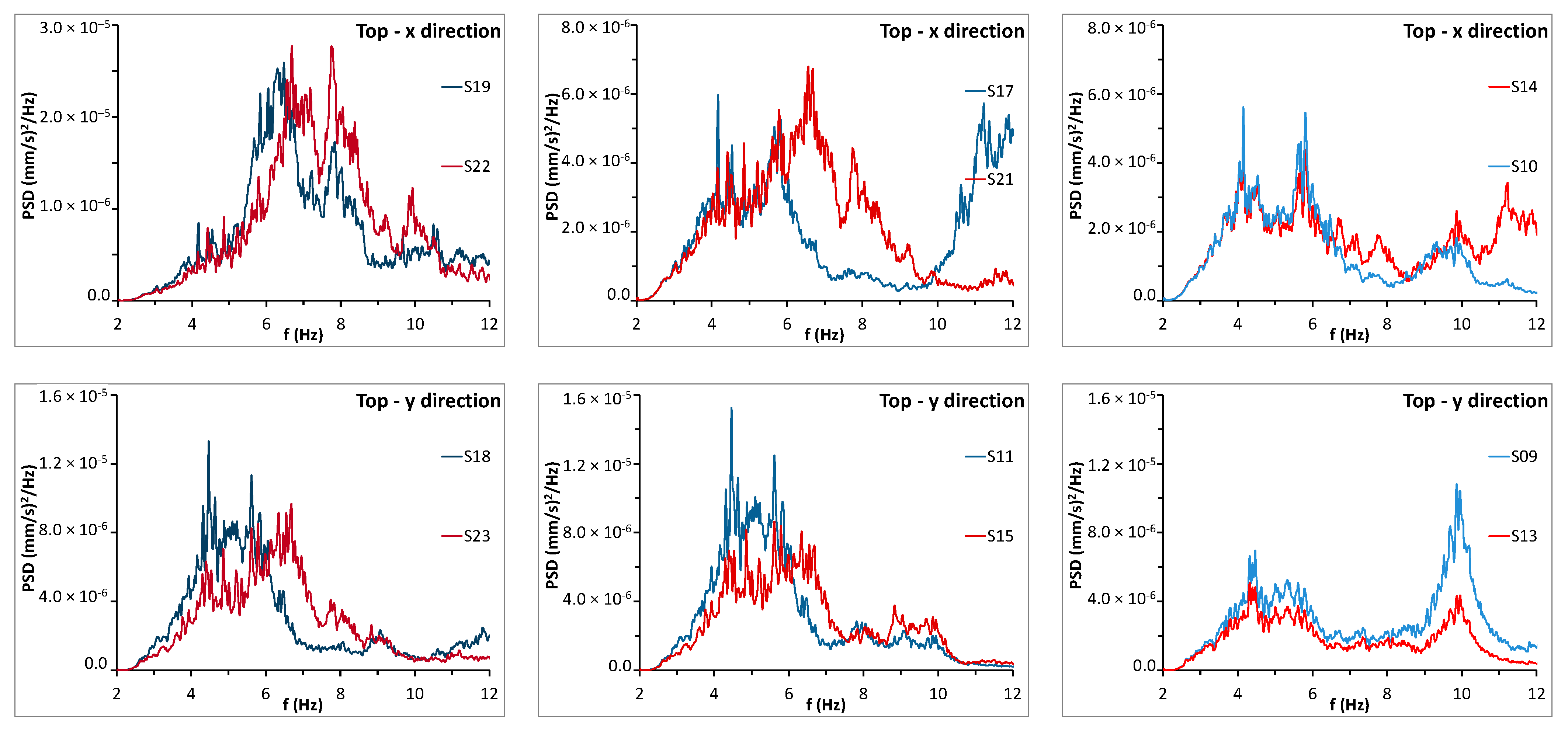
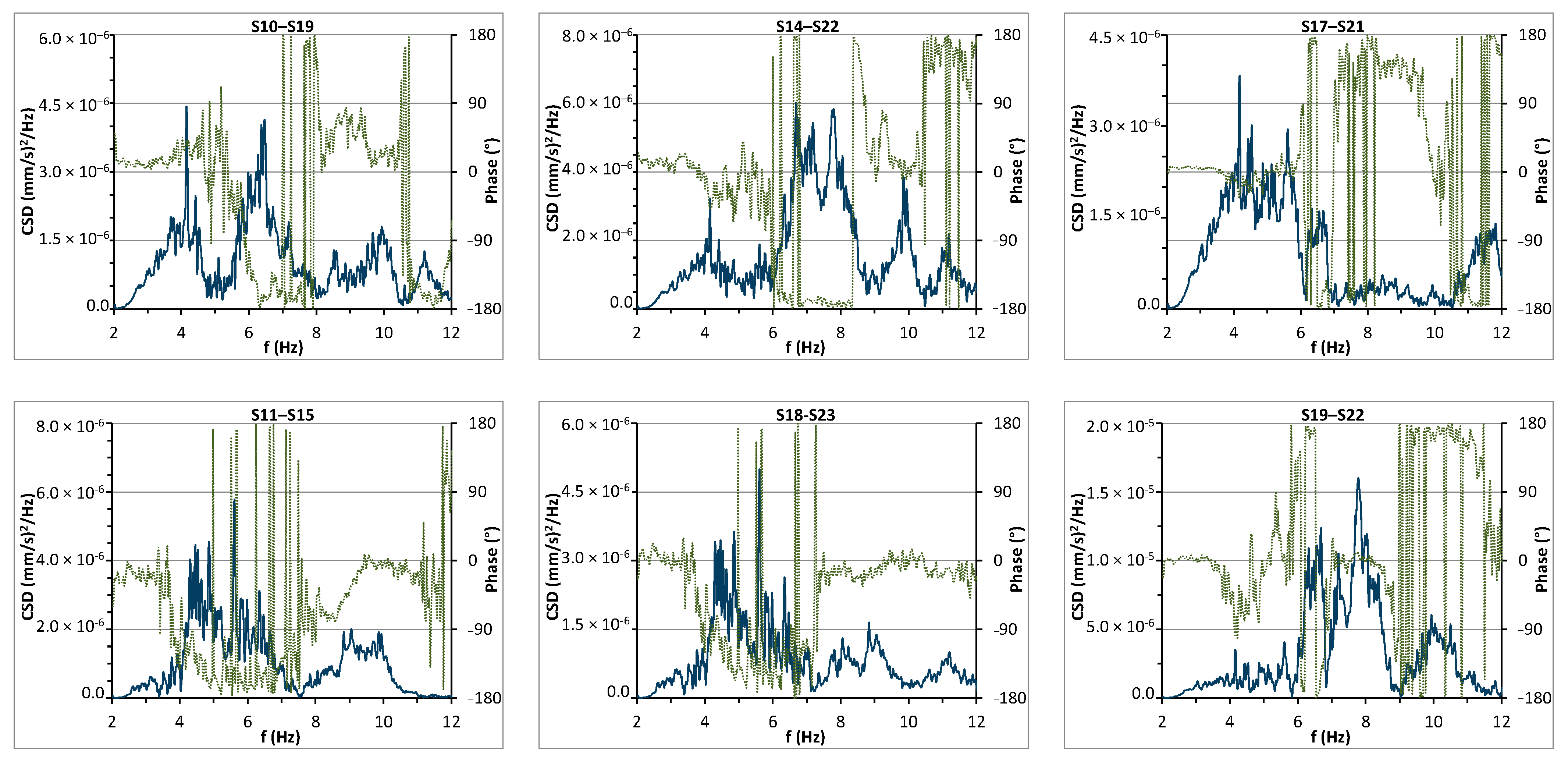
In Figure 3, the power spectral densities (PSDs) of the recordings obtained at the second floor are plotted. Because of many not well separated peaks in the spectra, a clear identification of frequencies and modal shapes is not possible. However, a stronger energy content of modes related with the motion of the two wings (i.e., lateral blocks) suggests a prevalent non-global behaviour of the building. Considering also the cross-spectral densities (CSDs) (Figure 4), the following significant resonance frequencies were individualized.
  • A first resonance frequency at 4.15 Hz involves the entire building in the x direction, with displacements of the same order for all the sensor locations.
  • The first resonance frequency of 4.47 Hz in the y direction, like the previous one, involves the entire building; however, in this case, the modal components at the external walls are about double of those at S09 and S13.
  • The third resonance frequency, equal to 5.62 Hz, is still in the y direction; it also involves the entire building and, as above, the modal components at the external walls are about twice as those at S09 and S13.
  • The resonance frequency of 5.81 Hz is likely to correspond with a mode of the whole building in the x direction; in this case, the modal components of the main body are similar to each other, while those of the wing (S19 and S22) are much higher.
  • The resonance frequency of 6.69 Hz refers to the right wing, both in the x and y directions.
  • Analogously, the resonance frequency of 7.84 Hz refers to the right wing, both in x and y directions.
  • The resonance frequency of 9.86 Hz, which, once again, concerns the main block in the y direction, involves different signal amplitudes for the sensors of the second floor (S09 and S13) and highlights a certain deformability of that floor in its plane.
  • Finally, the resonance frequency of 11.2 Hz corresponds to a mode engaging the two lateral blocks in the x direction.
In Figure 5, the PSDs of all the recordings at the first floor and those at the basement are plotted. As can be seen, the same resonance frequencies highlighted in the recordings of the second floor are also present for the first floor, with low energy. The spectra of the recordings at the basement also contain other lower frequency components.

3.2. Time Domain Analysis

In order to analyse the dynamic behaviour of the building in depth, signals were also studied in the time domain.
As pointed out by the frequency domain analysis, the flexibility of the horizontal slabs should be analysed in more detail so as to investigate how it is likely to assume that floors are rigid in their plane. Furthermore, if a pushover analysis is intended to be performed, information is needed to establish whether it is legitimate to assume the centre of mass of the top floor as the control node. According to current Italian Code [37,38], in the case of a floor having finite stiffness, the displacement to be used into the capacity plot should be a weighted average among the displacements at the top of the vertical walls.
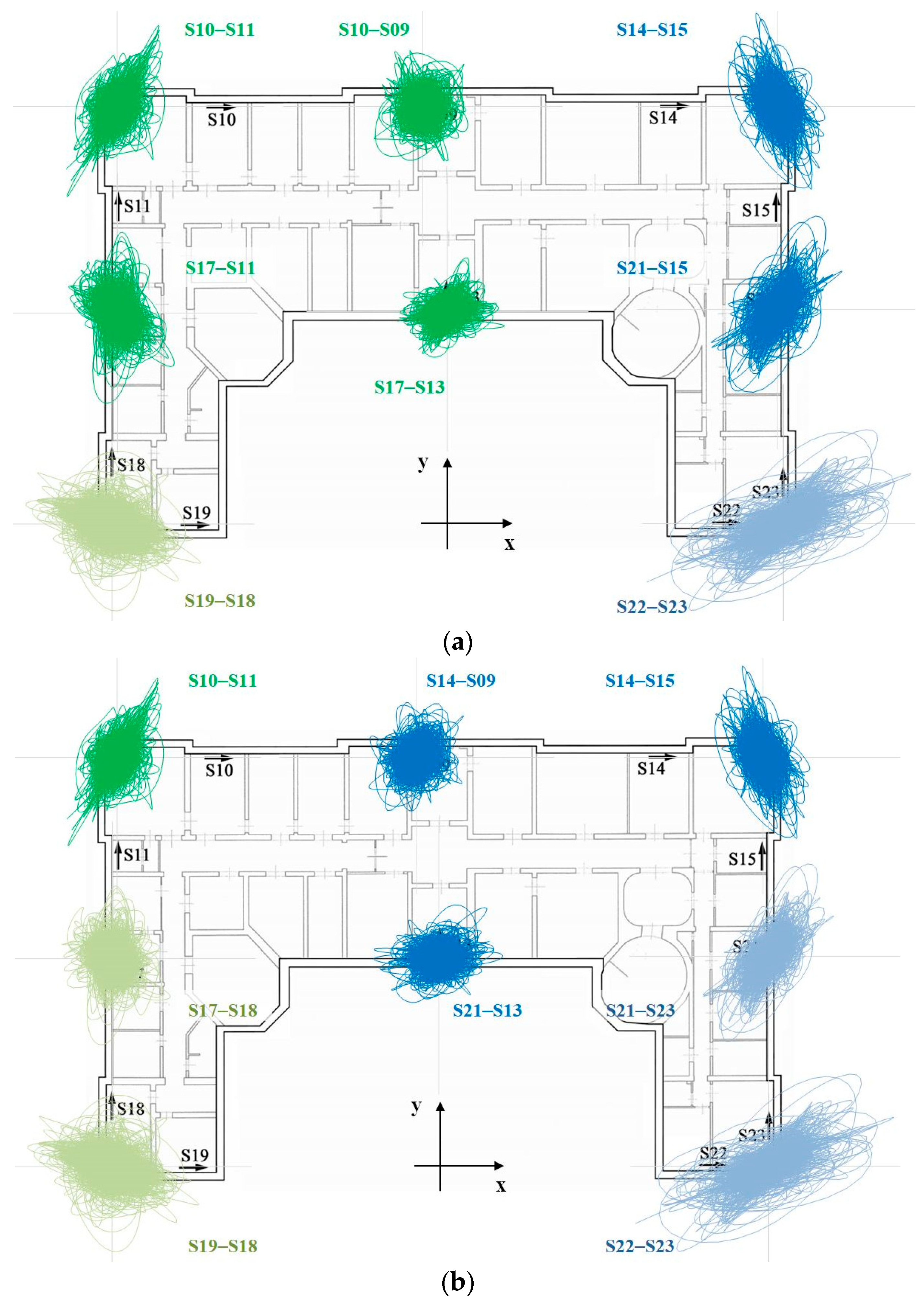
If an adequate number of experimental recordings are available, a way to check if a system behaves like a rigid body is to try to find a unique centre of rotation by intersecting the straight lines perpendicular to the motion direction at the measurement points. In Figure 6a,b, the particle motions at the main corners of the building and at the intermediate points of the façades were superimposed onto the second-floor plan. The two figures differ because at each intermediate point, the sensor orthogonal to the façade was coupled with the two different sensors parallel to the same façade, which means to translate each sensor parallel to a façade along its axis up to the sensor at its right angle. This way of proceeding implies neglecting the floor deformation, which is a plausible assumption when the start and end points of translation are close to each other and lined up along the perimeter of the building.
It is immediately evident that the prevalent directions of motion of the building do not correspond to the two main horizontal axes. This occurrence is related to the irregular C-shape of the building in plane. Moreover, whereas a certain behavioural symmetry with respect to the y axis is found for the main body, the same is not true for the two wings (sectors C and D in the following), because the right wing moves much more than the left one.
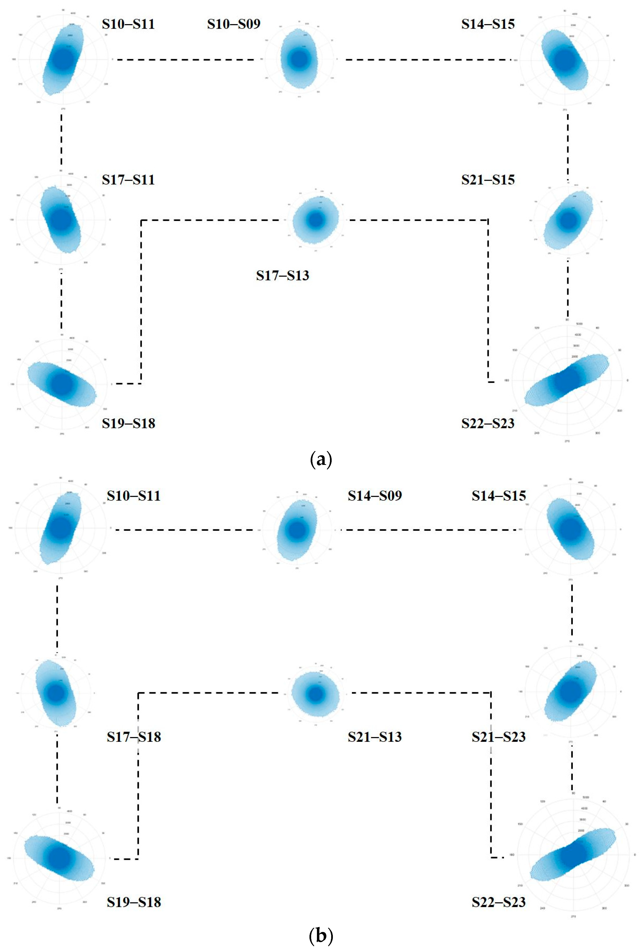
A more detailed representation of motion direction at each measurement point can be obtained through angle distributions, which report the number of times a particle motion is oriented in a certain direction with an approximation of a one-degree angle (Figure 7a,b). The tangles we obtained have quite a regular shape, approximating an ellipse. Then, from each angle distribution, the prevailing direction of motion can be made to coincide with the major axis of this ellipse, whereas the minor one can be assumed as a measure of the dispersion. In other words, the more the approximation ellipse will be elongated and narrowed, the more the movement of the point will keep a constant inclination over time. In contrast, the more the approximation ellipse will be rounded, the more the movement of the point will change direction over time. From the figures, it can be seen that corners have a behaviour closer to the first category, whereas intermediate points fall into the second one, exhibiting a more significant dispersion of the direction of motion. Moreover, the tangles at intermediate points S09 and S13 differ depending on whether they are coupled with the sensor to their right or with the one to their left.
What has been performed at intermediate points—assuming that along the translation path of sensors, the floor is rigid—likely seems to be the reality in the cases of points S17 and S21, but not in the case of S09 and S13. This is also confirmed by semi-sum and semi-difference time histories between the corresponding translated sensors (Figure 8 and Figure 9). Indeed, while it appears that sensors S18−S11 move mainly in phase, as well as sensors S15–S23, this conclusion is weaker for sensors S14−S10 and far from reality for sensors S17–S21.
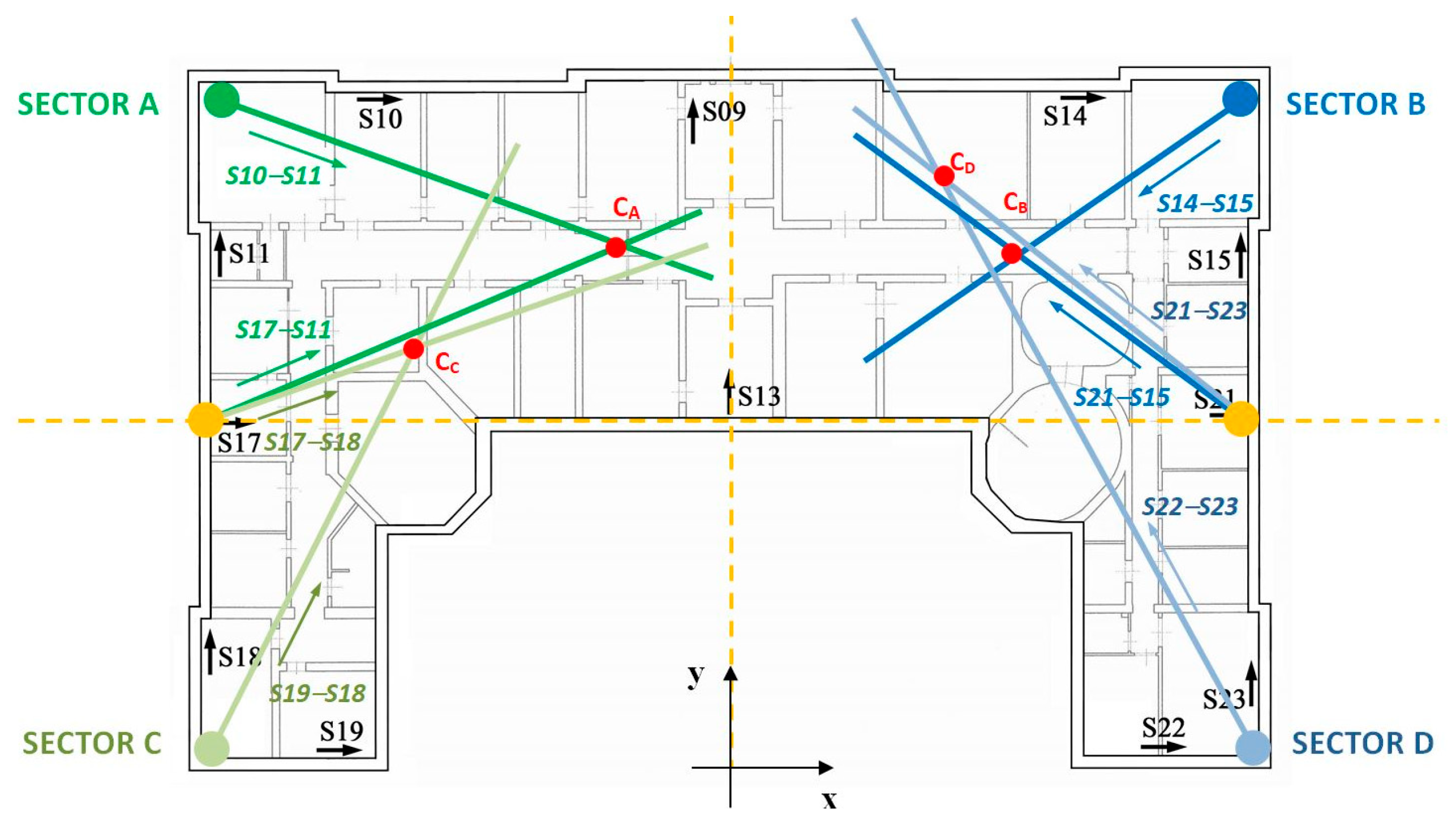
Neglecting the dispersion of motion, we will assume that the centre of rotation compatible with the movement of a point is located along the minor axis of the approximation ellipse centred at that point. By applying this rule for each angle distribution in Figure 7, the lines shown in Figure 10 were obtained. It is worth noting that both the contributions of sensors S09 and S13 were excluded from this procedure, as we believe that inferring a prevalent motion direction from their angle distributions is relatively unreliable. On the other hand, the analysis of the frequency domain (see Figure 3) highlighted—for these sensors and unlike the others—the most significant peak on the PSD, at around 9.86 Hz.
If the floor were perfectly rigid, all lines would intersect at a unique point, which would be the floor’s exact centre of rotation. This is not the case, and, even if we excluded the two wings, a unique centre of rotation for the main body would not be evident. However, important information on the behaviour of the building may be inferred. For ease of reading, the plan was divided into four sectors: sectors A and B include the left side and right side of main body, respectively, whereas sectors C and D are the left wing and the right wing, respectively. What is immediately noticeable is that the direction of the centre of rotation for S17–S11 is almost coincident with the direction of S17–S18; and the direction of S21–S15 is almost coincident with the direction of S21–S23. This circumstance can be considered representative of the fact that, near the two secondary façades, the floor is quite rigid. However, keeping into account all the directions we deduced, four different centres of rotation were obtained (one for each sector: CA, CB, CC and CD in Figure 10). It is interesting to observe that CA and CB are aligned along x at about half the height of the main body, whereas the positions of CC and CD confirm that the two wings do not have symmetrical behaviour. Moreover, the distances of these two centres from the corresponding wings are compatible with the greater displacements recorded on the right corner (see Figure 6) with respect to the left one.

4. Finite Element Model

4.1. Confined Masonry Walls Model

The confined masonry buildings, even now largely widespread in Latin American countries such as Chile and Mexico, most likely appeared in the Italian overview after the Reggio Calabria and Messina earthquake of 28 December 1908, and the already mentioned Avezzano earthquake of 1915. Therefore, they are likely to be found among the historical or merely old buildings. The construction technique is based on masonry provided with reinforced concrete or reinforced masonry confining elements in the vertical and horizontal directions.
In the recent Italian Technical Code [37,38], some prescriptions are given for the design of new constructions with confined masonry, concerning the geometrical characteristics (e.g., minimum thickness, slenderness), the positioning of the reinforced concrete’s vertical and horizontal elements, as well as their spacing, the minimum quantities of the reinforcing bars and stirrups and the construction phases (e.g., the concrete of the confining elements must be cast after the masonry realization). Furthermore, confined masonry is considered more reliable than ordinary masonry and higher values of the behaviour factor are allowed. The Italian Code refers to the European Standards [39] for the check. According to these, the shear resistance of a confined masonry member should be taken as the sum of the shear resistance of the masonry and that of the concrete of the confining elements.
In the following, the mathematical model proposed by Tomazevic and Klemenc [40], and agreed by Ahmad et al. [41], is used. It considers the shear resistance V of the confined masonry as the sum of the contribution of the masonry Vm (for diagonal shear damage mechanism) and of the reinforced concrete elements VS (due to the dowel action of reinforcing steel), whose expressions are given below:
V m = τ 0 l t C i b   1 + C i 2 1 + σ 0 τ 0 + 1
V S = 0.8059 n ϕ 2 f C f S    
where:
  • C i = 2 α b l / h     is the interaction coefficient (α = 1.25);
  • τ 0 = Shear strength of masonry without compression;
  • l = Wall base width;
  • t = Thickness;
  • h = Height;
  • b = h/l, but 1.0 ≤ b ≤ 1.5;
  • σ0 = Vertical stress on the wall;
  • n = Number of reinforcing bars;
  • ϕ = Diameter of reinforcing bar;
  • fc = Compressive strength of concrete;
  • fy = Yield stress of reinforcing steel.
This model is derived from experimental analyses on specimens of confined and not confined masonry walls tested under a constant vertical load and a programmed pattern of cyclically acting horizontal displacements, while keeping the lower and upper boundaries of the specimen parallel to each other. From the tests conducted, the authors found that lateral resistance and deformation capacity both improve in the confined masonry in comparison with the non-confined one. They attributed the improvement of shear resistance to the additional compression stresses, derived from interaction forces developed between the confining elements and masonry at the contact zones, and to the dowel action of reinforcing bars once the masonry panel is cracked. These two phenomena involve, on the one hand, a modification into the expression of the shear resistance of plain masonry walls, which lead us to obtain Equation (1), and on the other hand, the addition of the contribution of Equation (2) to the total shear resistance of confined masonry.
Nevertheless, with reference to the confined masonry, but as far as bending and/or axial loading are concerned, Eurocode 6 establishes that “in determining the design value of the moment of resistance of a section, a rectangular stress distribution may be assumed, based on the strength of the masonry, only. Reinforcement in compression should also be ignored”. It follows that the resistance moment can be computed according to the expression provided by the Italian National Technical Code for unreinforced masonry:
M R d = l 2 t σ 0 2     1 σ 0 0.85 f d
In Equation (3), fd is the design compression strength of the masonry, whereas the other symbols are as previously defined above.

4.2. Model of the Building

A finite element model of the structure (Figure 11) was set up by resorting to the equivalent frame method [42]. The above results of experimental analysis provided relevant information and support in realizing a model, which was reliable and close to reality. For its calibration, not only the mechanical parameters, determined on the basis of traditional tests, but also the findings of experimental vibration analysis were used. The latter highlighted, in particular, the need to take into account the floors’ deformability. Assuming that the floor diaphragms were planar rigid bodies, as is usually the case, it would have been an oversimplification in this case.
For simulations, the computer code SAP2000 was used. The walls and the masonry spandrels were modelled by means of equivalent “beam” elements with rigid zones at their ends. Floors were modelled by means of “shell” elements having membrane behaviour only, in order to simulate their in-plane response with the effective stiffness, and rigidly connected to the masonry walls.
As for the materials’ properties, the experimental results given in Section 2 were elaborated, according to the Italian Technical Code, as summarized below.
The experimental strength values of masonry were multiplied for a factor equal to 1.3 to account for the presence of effective transversal connections in the walls. These strength values must be further divided by a partial safety factor γ M (= 2 for seismic load combination, and = 3 for vertical load combination) when linear analyses are performed.
Regarding the concrete, from the average experimental cube strength, the corresponding average experimental cylindrical strength fcm = 10.9 N/mm2 and the Young’s modulus Ecm = 22,579 N/mm2 were derived. Having no experimental tests for steel bars, the yield strength was assumed equal to fy = 350 N/mm2, consistent with the characteristics of the steel used at the time of construction.
Finally, a reduction factor equal to 1.2 was applied to the material strengths based on the knowledge level (LC) reached. It was classified as level 2 (LC2), which is an intermediate level between the lowest (LC1) and the highest (LC3). As a consequence, the concrete’s reduced cylindrical strengths fcd = 9.05 N/mm2, for ductile mechanisms, and fcd,f = 6.03 N/mm2, for brittle mechanisms, were obtained. Similarly, fyd = 253.27 N/mm2 represents the steel yield strength for brittle mechanisms.

4.3. Modal Analysis

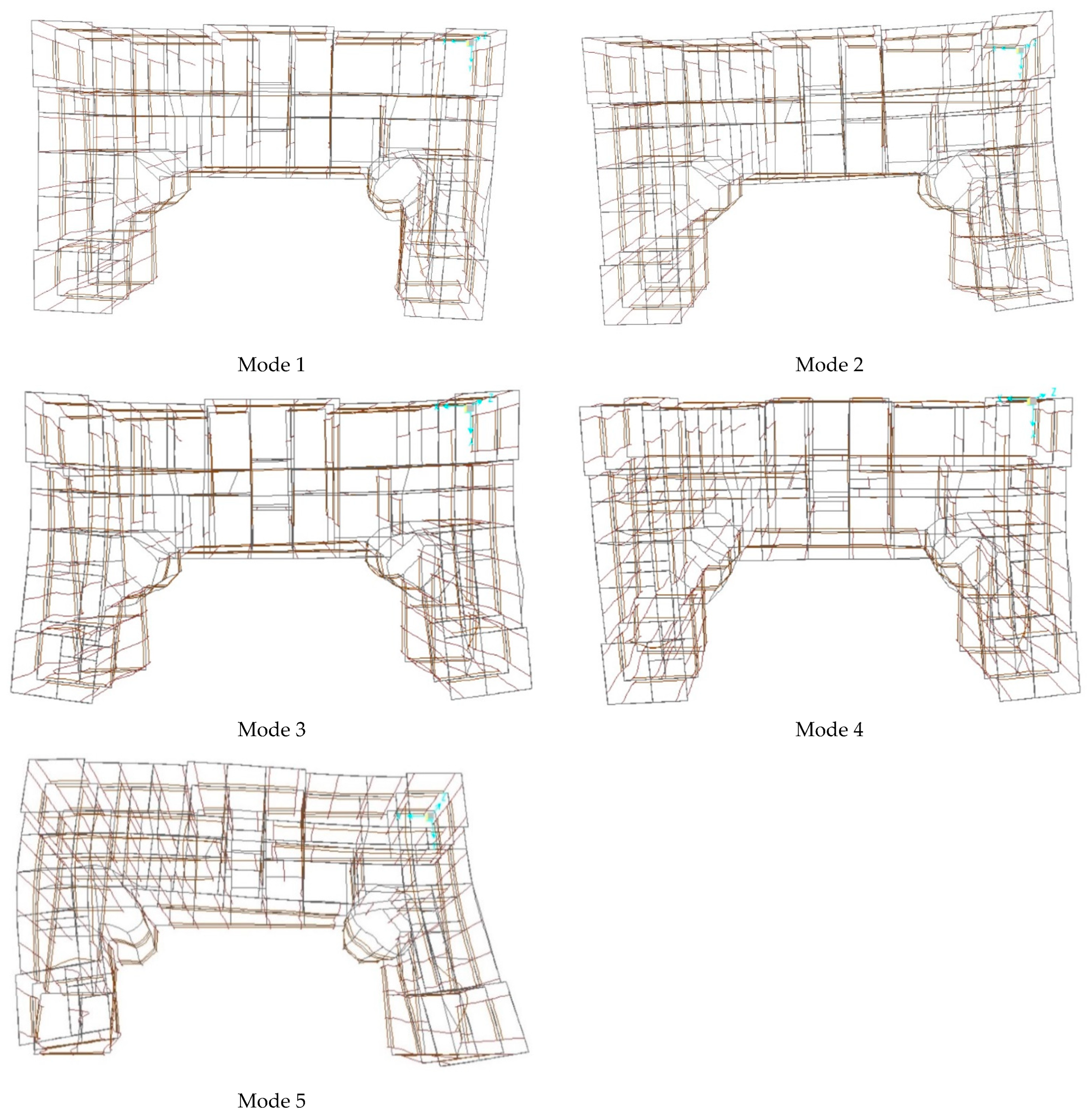
Results of modal analysis in terms of frequencies are summarized in Table 1, the first five modal shapes are reported in Figure 12. The correspondence with the experimental resonance frequencies is quite good, except for the first two, and in general, modal shapes agree sufficiently well with experimental findings. In detail, the first mode shows prevalent displacements in the x direction for the whole building. The second mode is instead mainly based on an x-directed movement of sector D; for this latter mode, the motion of the points experimentally investigated has outstanding similarities with those observed in the particle motion. The third mode is related to the x-motion of sectors C and D, 180° out of phase, and flexural y-motion of portion A + B. The fourth mode is mainly y-directed for the whole building with an x-component of sector C. Finally, mode 5 is related to the in-phase motion of the flanges in the x direction and the two-wave flexural motion of portion A + B in the y direction.
The modal analysis underscored the importance of multimodal approaches in a seismic nonlinear static analysis, and the selection of different control nodes for the target displacement to obtain a reliable displacement–base shear capacity curve of the structure.

5. Push-Over and Response Spectrum Analyses

As is well known, the pushover analysis consists of applying different distributions of monotonically increasing horizontal forces at the floors of the building. When the forces are increased, a target displacement of a control node is observed to obtain a force–displacement capacity curve. The force is the base total shear resultant, while the centre of the mass of the top level of the building is usually chosen as control node. However, if a significant torsional–translation coupling is present, as in our case, extreme points of the top level should also be considered. This was also performed.
Material nonlinearities were taken into account, in terms of shear and bending or combined axial-bending behaviours, by modelling the walls and masonry spandrels as elastic beam elements with elasto–perfect plastic behaviour at the two ends. As limit values of the shear and moment, those evaluated by Equations (1)–(3) were assumed, from which the corresponding deformation parameter values can be deduced. The collapse displacement capacity was assumed equal to du = 0.006·h (where h is the equivalent height of the wall) for the shear mechanism, whereas the ultimate limit of 0.008 was established for the rotation for the axial-bending mechanism.
Two different kinds of forces distributions were applied:
-
Main distribution, where forces are proportional to one of the main modal shapes in x or y direction, respectively.
-
Secondary distribution, in which forces are proportional to the masses.
The two horizontal components of the forces were applied separately, and the effects obtained in the worst case were assumed as the maximum ones.
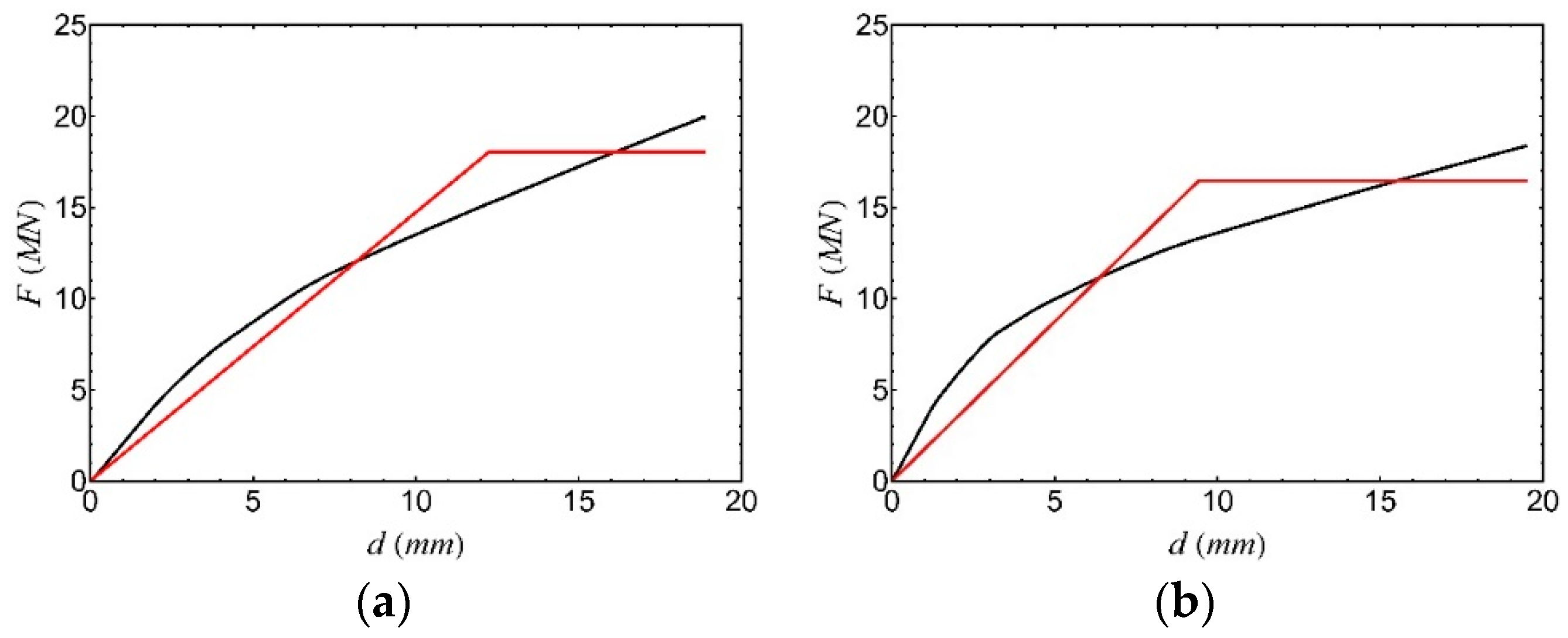
With reference to the main distribution, the analyses were performed considering in sequence the modes with a significant participating mass. In Figure 13, the two collapse mechanisms, obtained in the case of the first (x direction) and the fourth (y direction) modal shapes, respectively, are shown for comparison. The corresponding force–displacement curves of the structure (Figure 14) were drawn, assuming as control node, in each case, the node that has the largest modal displacement in each case. The curves were bi-linearized through the criterion of energy equality and scaled by means of the participation factors of the considered modes to obtain the capacity curves, which refer to the equivalent one-degree-of-freedom system.
As it is evident from the figures, the worst (lower) capacity value corresponds to the fourth mode distribution. The analyses carried out with the secondary distribution of forces showed a higher capacity than those performed by means of the main ones and, therefore, the results herein have been omitted.
The aim of performing a nonlinear static analysis was dual: on the one hand, it was to check the structural seismic capacity agc (by comparing the capacity curves with the demand requested from the spectrum of the site), and on the other hand, to determine the behaviour factor q (to use in a response spectrum analysis).
  • The minimum value of the capacity peak ground acceleration, with reference to the rigid soil, was found to be equal to agc = 0.151 g and was achieved, as mentioned above, in the case of a force distribution proportional to the fourth mode in y direction. It corresponds to a return period TRC = 139 years.
  • According to the Italian Technical Code, the behaviour factor for confined masonry buildings is q = 2 α u / α 1   . These values must be multiplied by 0.8 if the building is irregular in height. The ratio α u / α 1   , between the 90% of the seismic action at which the structure reaches its maximum strength and the seismic action at which the first masonry panel reaches its ultimate strength, can be evaluated by means of a nonlinear static analysis (but, in any case, it must be α u / α 1 2.5 ). In our case study, based on the results of pushover analysis, we computed the value q = 2.5.
However, it should be noted that, in the absence of a nonlinear static analysis, the value of α u / α 1   = 1.6 is suggested by the Italian Technical Code and can be assumed as a reference value. Moreover, for the structural typology under examination, the experimental results on models are also available in the literature. In [43], the authors found a behaviour factor q = 2.9 for the models tested on the shaking table. However, they recommended a value q = 2 for confined masonry to account for any irregularity of the building and the succession and localization of the plasticization that led to the collapse.
Given the uncertainties in modelling this structural typology, the vulnerability was also evaluated by means of a linear response spectrum analysis, reducing the elastic response spectrum with the behaviour factor q = 2.5 previously evaluated from the push-over analysis.
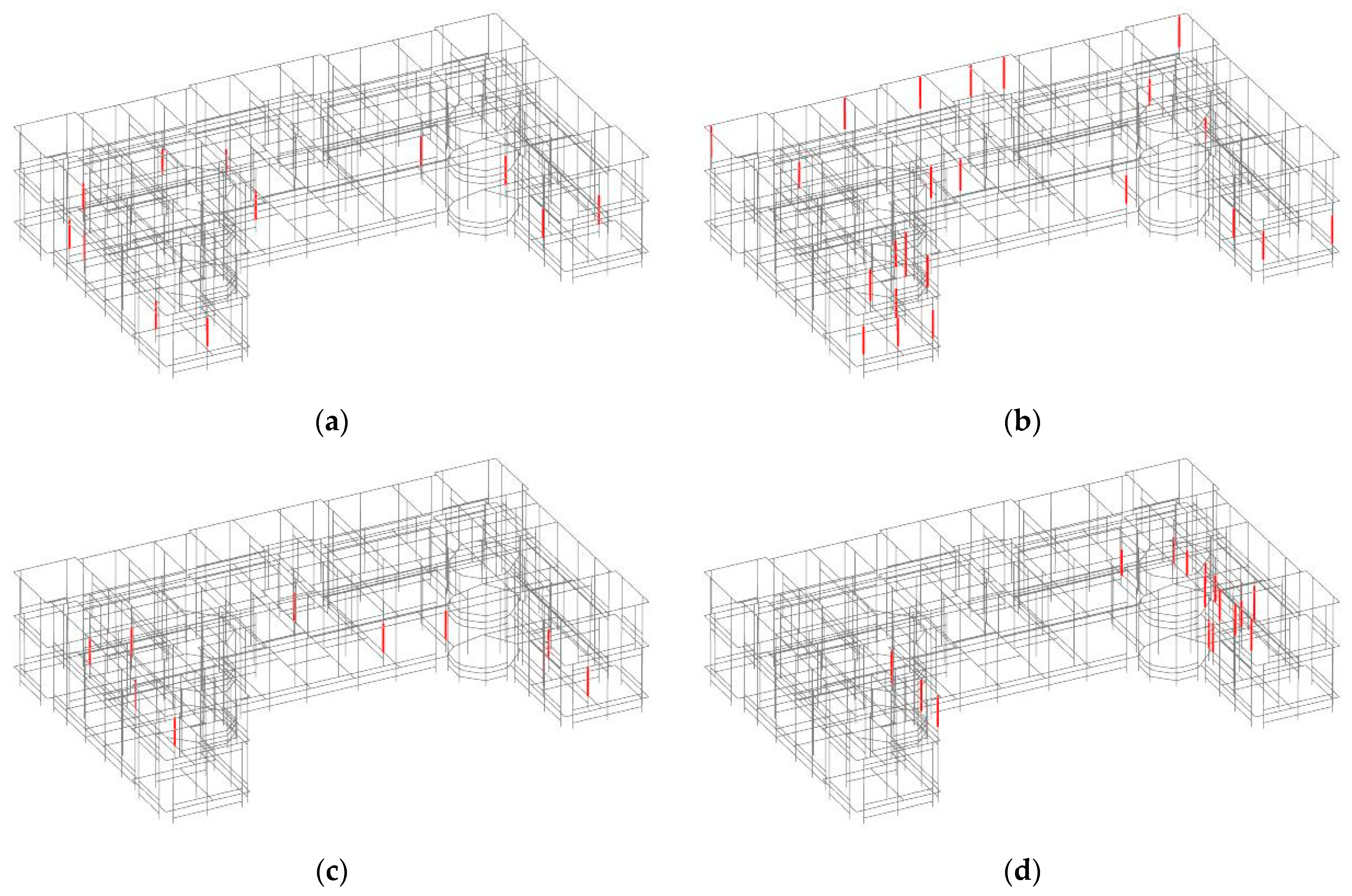
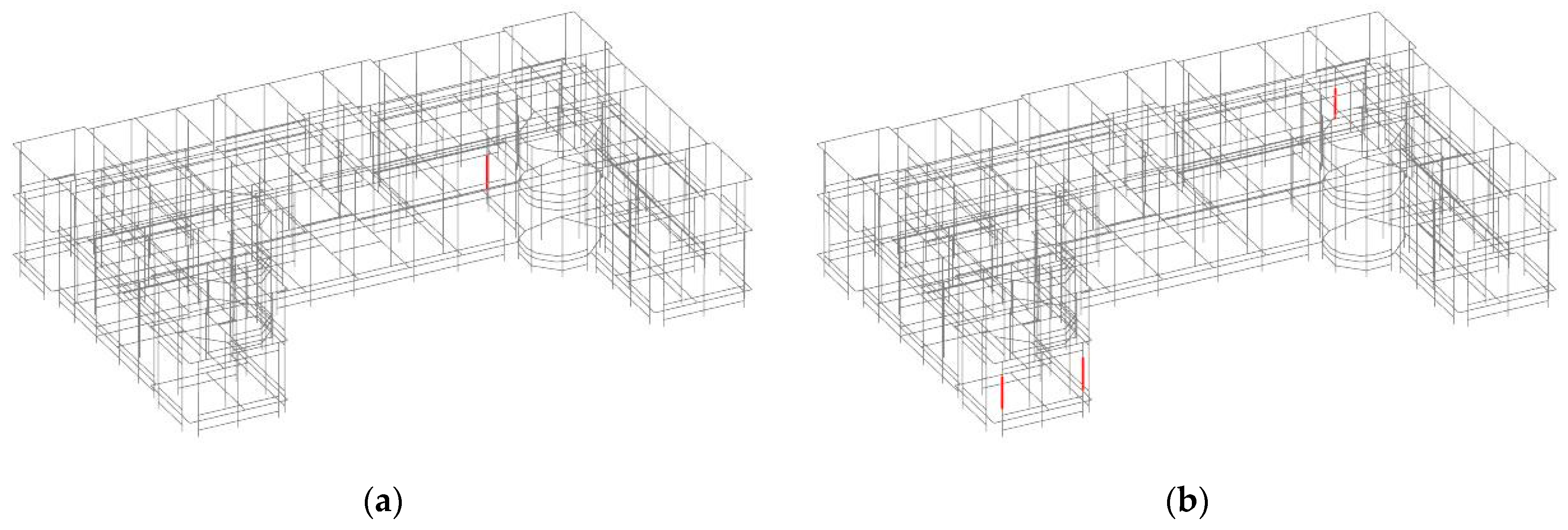
Figure 15a–d show the elements with a capacity/demand ratio (i.e., seismic the safety index) lower than 1 (TR = 475 years), whereas in Figure 16a,b, the few elements unable to support the demand for TR = 140 years are highlighted. It is therefore evident that the capacity peak ground acceleration obtained with the response spectrum analysis is very close to that obtained with the nonlinear static analysis.

6. Conclusions

The knowledge of an old masonry building is quite a hard task. Information about the material characteristics and structural details, such as the connections between the vertical walls and between these and the floors, are often missing and a reliable evaluation is impossible in practice. The experimental analysis represents the best and at times the only way to obtain reliable data. In particular, the experimental vibration analysis allows for analysing the actual behaviour in a dynamic condition and provides precious information for setting up a suitable numerical model to simulate the behaviour under seismic actions.
Keeping in mind these considerations, the knowledge process of a historic building has been presented in this paper. It represents a typical building realized during the reconstruction after the 1915 Avezzano earthquake, made of confined masonry and with deformable floors. The effects of these characteristics were pointed out by the analyses of the data obtained from an accurate experimental vibration campaign, both in time and frequency domains. The combined use of frequency and time domain analyses, in fact, allowed for highlighting the important features of the structural behaviour, mainly related to the deformability of the floors in their own plane. Resonance frequencies, modal shapes and the preferred movements of significant points of the floors were found.
The knowledge of these features allowed for the setting up of a finite element model. Confined masonry walls were modelled as elastic beam elements with elasto–perfect plastic behaviour at their ends, which takes into account both the contribution of the masonry and the reinforced concrete elements. Material characteristics were defined on the basis of the experimental results and following the literature on the subject. The better performance of the confined masonry was accounted for in terms of strength, by introducing appropriate factors, and behaviour factor of the building.
The numerical model reproduced quite well the actual modal shapes of the building and was used to evaluate its seismic capacity. Both nonlinear static and linear dynamic analyses were performed, which presented similar results in terms of structural capacity. The analysis also highlighted the weakest elements for shear and axial-bending mechanisms, which is useful information for any retrofit intervention.
A comparison with the corresponding rigid floor building and a proposal for the seismic improvement are the main steps for future developments.

Author Contributions

Conceptualization, C.T., F.S., P.C., G.B. (Giacomo Buffarini) and G.B. (Giovanni Bongiovanni); methodology, C.T., F.S., P.C., G.B. (Giacomo Buffarini) and G.B. (Giovanni Bongiovanni); software, C.T., F.S., P.C., G.B. (Giacomo Buffarini) and G.B. (Giovanni Bongiovanni); validation, C.T., F.S., P.C., G.B. (Giacomo Buffarini) and G.B. (Giovanni Bongiovanni); formal analysis, C.T., F.S., P.C., G.B. (Giacomo Buffarini) and G.B. (Giovanni Bongiovanni); investigation, C.T., F.S., P.C., G.B. (Giacomo Buffarini) and G.B. (Giovanni Bongiovanni); resources, C.T., F.S., P.C., G.B. (Giacomo Buffarini) and G.B. (Giovanni Bongiovanni); data curation, C.T., F.S., P.C., G.B. (Giacomo Buffarini) and G.B. (Giovanni Bongiovanni); writing—original draft preparation, C.T., F.S., P.C., G.B. (Giacomo Buffarini) and G.B. (Giovanni Bongiovanni); writing—review and editing, C.T., F.S., P.C., G.B. (Giacomo Buffarini) and G.B. (Giovanni Bongiovanni); visualization, C.T., F.S., P.C., G.B. (Giacomo Buffarini) and G.B. (Giovanni Bongiovanni); supervision, C.T., F.S., P.C., G.B. (Giacomo Buffarini) and G.B. (Giovanni Bongiovanni); project administration, P.C. and G.B. (Giacomo Buffarini); funding acquisition, P.C. and G.B. (Giacomo Buffarini) All authors have read and agreed to the published version of the manuscript.

Funding

This research received no external funding.

Data Availability Statement

Not applicable.

Acknowledgments

The research work leading to this paper has been the result of a joint effort between ENEA and the Municipality of Avezzano, Italy, for the evaluation and structural health monitoring of strategic historic buildings in the city of Avezzano.

Conflicts of Interest

The authors declare no conflict of interest.

References

  1. Rossi, M.; Bournas, D. Structural Health Monitoring and Management of Cultural Heritage Structures: A State-of-the-Art Review. Appl. Sci. 2023, 13, 6450. [Google Scholar] [CrossRef]
  2. Pierdicca, A.; Clementi, F.; Isidori, D.; Concettoni, E.; Cristalli, C.; Lenci, S. Numerical model upgrading of a historical masonry palace monitored with a wireless sensor network. Int. J. Mason. Res. Innov. 2016, 1, 74. [Google Scholar] [CrossRef]
  3. Bongiovanni, G.; Buffarini, G.; Clemente, P.; Rinaldis, D.; Saitta, F. Experimental vibration analyses of a historic tower structure. J. Civ. Struct. Health Monit. 2017, 7, 601–613. [Google Scholar] [CrossRef]
  4. Bongiovanni, G.; Buffarini, G.; Clemente, P.; Saitta, F. Time and Frequency Domain Analyses in the Experimental Dynamic Behaviour of the Marcus Aurelius’ Column. Int. J. Arch. Heritage 2019, 15, 64–78. [Google Scholar] [CrossRef]
  5. Bongiovanni, G.; Buffarini, G.; Clemente, P.; Rinaldis, D.; Saitta, F. Dynamic Characteristics of the Amphitheatrum Flavium northern wall from traffic-induced vibrations. Ann. Geophys. 2017, 60, S0439. [Google Scholar] [CrossRef]
  6. Bongiovanni, G.; Çelebi, M.; Clemente, P. The flaminio obelisk in Rome: Vibrational characteristics as part of preservation efforts. Earthq. Eng. Struct. Dyn. 1990, 19, 107–118. [Google Scholar] [CrossRef]
  7. Puzzilli, L.M.; Bongiovanni, G.; Clemente, P.; Di Fiore, V.; Verrubbi, V. Effects of Anthropic and Ambient Vibrations on Archaeological Sites: The Case of the Circus Maximus in Rome. Geosciences 2021, 11, 463. [Google Scholar] [CrossRef]
  8. Pellegrini, D.; Barontini, A.; Girardi, M.; Lourenço, P.; Masciotta, M.; Mendes, N.; Padovani, C.; Ramos, L. Effects of temperature variations on the modal properties of masonry structures: An experimental-based numerical modelling approach. Structures 2023, 53, 595–613. [Google Scholar] [CrossRef]
  9. Zonno, G.; Aguilar, R.; Boroschek, R.; Lourenço, P.B. Experimental analysis of the thermohygrometric effects on the dynamic behavior of adobe systems. Constr. Build. Mater. 2019, 208, 158–174. [Google Scholar] [CrossRef]
  10. Azzara, R.M.; De Roeck, G.; Girardi, M.; Padovani, C.; Pellegrini, D.; Reynders, E. The influence of environmental parameters on the dynamic behaviour of the San Frediano bell tower in Lucca. Eng. Struct. 2018, 156, 175–187. [Google Scholar] [CrossRef]
  11. Saisi, A.; Gentile, C.; Ruccolo, A. Continuous monitoring of a challenging heritage tower in Monza, Italy. J. Civ. Struct. Health Monit. 2017, 8, 77–90. [Google Scholar] [CrossRef]
  12. Gentile, C.; Guidobaldi, M.; Saisi, A. One-year dynamic monitoring of a historic tower: Damage detection under changing environment. Meccanica 2016, 51, 2873–2889. [Google Scholar] [CrossRef]
  13. Ramos, L.F.; Marques, L.; Lourenço, P.B.; De Roeck, G.; Campos-Costa, A.; Roque, J. Monitoring historical masonry structures with operational modal analysis: Two case studies. Mech. Syst. Signal Process. 2010, 24, 1291–1305. [Google Scholar] [CrossRef]
  14. De Angelis, A.; Lourenço, P.B.; Sica, S.; Pecce, M.R. Influence of the ground on the structural identification of a bell-tower by ambient vibration testing. Soil Dyn. Earthq. Eng. 2022, 155, 107102. [Google Scholar] [CrossRef]
  15. De Stefano, A.; Matta, E.; Clemente, P. Structural health monitoring of historical heritage in Italy: Some relevant experiences. J. Civ. Struct. Health Monit. 2016, 6, 83–106. [Google Scholar] [CrossRef]
  16. Chiorino, M.A.; Ceravolo, R.; Spadafor, A.; Fragonara, L.Z.; Abbiati, G. Dynamic Characterization of Complex Masonry Structures: The Sanctuary of Vicoforte. Int. J. Arch. Heritage 2011, 5, 296–314. [Google Scholar] [CrossRef]
  17. Clemente, P. Extending the life-span of cultural heritage structures. J. Civ. Struct. Health Monit. 2018, 8, 171–179. [Google Scholar] [CrossRef]
  18. De Canio, G.; Muscolino, G.; Palmeri, A.; Poggi, M.; Clemente, P. Shaking Table Tests Validating Two Strengthening Interventions on Masonry Buildings. In Proceedings of the AIP Conference Proceedings, 2008 Seismic Engineering International Conference commemorating the 1908 Messina and Reggio Calabria Earthquake, MERCEA’08, Reggio Calabria, Italy, 24–27 June 2008; American Institute of Physics: Melville, NY, USA; Volume 1020, pp. 896–903. [Google Scholar] [CrossRef]
  19. Pepi, C.; Cavalagli, N.; Gusella, V.; Gioffrè, M. Damage detection via modal analysis of masonry structures using shaking table tests. Earthq. Eng. Struct. Dyn. 2021, 50, 2077–2097. [Google Scholar] [CrossRef]
  20. Boccamazzo, A.; Di Emidio, G.; Diotaiuti, G.; Dudine, A.; Asta, A.D.; Micozzi, F.; Morici, M.; Liberatore, D.; Addessi, D.; Buffarini, G.; et al. Push ‘o ver: A pushover test program on an existing brickwork construction. Procedia Struct. Integr. 2023, 44, 51–58. [Google Scholar] [CrossRef]
  21. Clemente, P.; Rinaldis, D.; Buffarini, G. Experimental Seismic Analysis of a Historical Building. J. Intell. Mater. Syst. Struct. 2007, 18, 777–784. [Google Scholar] [CrossRef]
  22. Clemente, P.; Delmonaco, G.; Puzzilli, L.M.; Saitta, F. Stability and seismic vulnerability of the stylite tower at umm ar-rasas. Ann. Geophys. 2019, 61, 49. [Google Scholar] [CrossRef]
  23. Aras, F.; Krstevska, L.; Altay, G.; Tashkov, L. Experimental and numerical modal analyses of a historical masonry palace. Constr. Build. Mater. 2011, 25, 81–91. [Google Scholar] [CrossRef]
  24. Misir, I.S.; Yucel, G. Numerical Model Calibration and a Parametric Study Based on the Out-Of-Plane Drift Capacity of Stone Masonry Walls. Buildings 2023, 13, 437. [Google Scholar] [CrossRef]
  25. Sivori, D.; Lepidi, M.; Cattari, S. Ambient vibration tools to validate the rigid diaphragm assumption in the seismic assessment of buildings. Earthq. Eng. Struct. Dyn. 2019, 49, 194–211. [Google Scholar] [CrossRef]
  26. Pagnoni, T. Seismic analysis of masonry and block structures with the discrete element method. In Proceedings of the 10th European Conference on Earthquake Engineering, Vienna, Austria, 28 August–2 September 1994; Volume 3, pp. 1669–1674. [Google Scholar]
  27. Lemos, J.V. Discrete Element Modeling of Masonry Structures. Int. J. Arch. Heritage 2007, 1, 190–213. [Google Scholar] [CrossRef]
  28. Pulatsu, B.; Erdogmus, E.; Lourenço, P.B.; Lemos, J.V.; Tuncay, K. Simulation of the in-plane structural behavior of unreinforced masonry walls and buildings using DEM. Structures 2020, 27, 2274–2287. [Google Scholar] [CrossRef]
  29. Du, H.; Yu, J.; Wang, Y.; Zhu, Y.; Tang, Y.; Wang, H. Visualized Failure Prediction for the Masonry Great Wall. Buildings 2022, 12, 2224. [Google Scholar] [CrossRef]
  30. Clemente, P.; Buffarini, G. Dynamic Response of Buildings of the Cultural Heritage. In Enciclopedia of Structural Health Monitoring; Boller, C., Chang, F.K., Fujino, Y., Eds.; John Wiley & Sons Ltd.: Chichester, UK, 2009; pp. 2243–2252. ISBN 978-0-470-05822-0. [Google Scholar] [CrossRef]
  31. De Stefano, A.; Clemente, P. Structural health monitoring of historical structures. In Structural Health Monitoring of Civil Infrastructure Systems; Karbhari, V.M., Ansari, F., Eds.; Woodhead Publishing Ltd.: Cambridge, UK, 2009; Chapter 13; pp. 412–434. [Google Scholar] [CrossRef]
  32. Giraldo, D.F.; Song, W.; Dyke, S.J.; Caicedo, J.M. Modal Identification through Ambient Vibration: Comparative Study. J. Eng. Mech. 2009, 135, 759–770. [Google Scholar] [CrossRef]
  33. De Sortis, A.; Antonacci, E.; Vestroni, F. Dynamic identification of a masonry building using forced vibration tests. Eng. Struct. 2005, 27, 155–165. [Google Scholar] [CrossRef]
  34. Lorenzoni, F.; Casarin, F.; Caldon, M.; Islami, K.; Modena, C. Uncertainty quantification in structural health monitoring: Applications on cultural heritage buildings. Mech. Syst. Signal Process. 2016, 66–67, 268–281. [Google Scholar] [CrossRef]
  35. Pachón, P.; Infantes, M.; Cámara, M.; Compán, V.; García-Macías, E.; Friswell, M.I.; Castro-Triguero, R. Evaluation of optimal sensor placement algorithms for the Structural Health Monitoring of architectural heritage. Application to the Monastery of San Jerónimo de Buenavista (Seville, Spain). Eng. Struct. 2019, 202, 109843. [Google Scholar] [CrossRef]
  36. Bongiovanni, G.; Buffarini, G.; Clemente, P.; Saitta, F.; Tripepi, C. Experimental analysis of the Torlonia Building in Avezzano, Italy. In Proceedings of the 7th International Conference on Advances in Experimental Structural Engineering, Pavia, Italy, 6–8 September 2017; EUCENTRE Foundation, Pavia, Italy: 2017. 2017; pp. 841–853. [Google Scholar] [CrossRef]
  37. NTC 2018. Aggiornamento delle Norme Tecniche per le Costruzioni. DM MIT 17 January 2018, Supplemento Ordinario n. 8 alla Gazzetta Ufficiale, 2018, Serie Generale n. 42 of 20 February 2018. Available online: https://www.gazzettaufficiale.it/eli/gu/2018/02/20/42/so/8/sg/pdf (accessed on 5 May 2023).
  38. Circ. MIT 7/2019. Istruzioni per l’applicazione dell’«Aggiornamento delle “Norme tecniche per le costruzioni”» di cui al DM 17 gennaio 2018, Circolare C.S.LL.PP. n. 7, 21 gennaio 2019, Gazzetta Ufficiale n. 35/2019. Available online: https://www.gazzettaufficiale.it/eli/gu/2019/02/11/35/so/5/sg/pdf (accessed on 5 May 2023).
  39. EN 1996. Design of Masonry Structures. Eurocode 6, CEN 2022. Available online: https://eurocodes.jrc.ec.europa.eu/EN-Eurocodes/eurocode-6-design-masonry-structures (accessed on 5 May 2023).
  40. Tomaževič, M.; Klemenc, I. Seismic behaviour of confined masonry walls. Earthq. Eng. Struct. Dyn. 1997, 26, 1059–1071. [Google Scholar] [CrossRef]
  41. Ahmad, N.; Ali, Z.; Ashraf, M.; Alam, B. Performance assessment of low–rise confined masonry structures for Earthquake induced ground motions. Int. J. Civ. Struct. Eng. 2012, 2, 842–859. [Google Scholar] [CrossRef]
  42. Magenes, G.; Della Fontana, A. Simplified non-linear seismic analysis of masonry buildings. In Proceedings of the British Masonry Society, London, UK, 13–15 October 1998. [Google Scholar]
  43. Tomaževič, M.; Bosiljkov, V.; Weiss, P. Structural Behaviour Factor for Masonry Structures. In Proceedings of the 13th World Conference on Earthquake Engineering (13WCEE), Vancouver, BC, Canada, 1–6 August 2004. [Google Scholar]
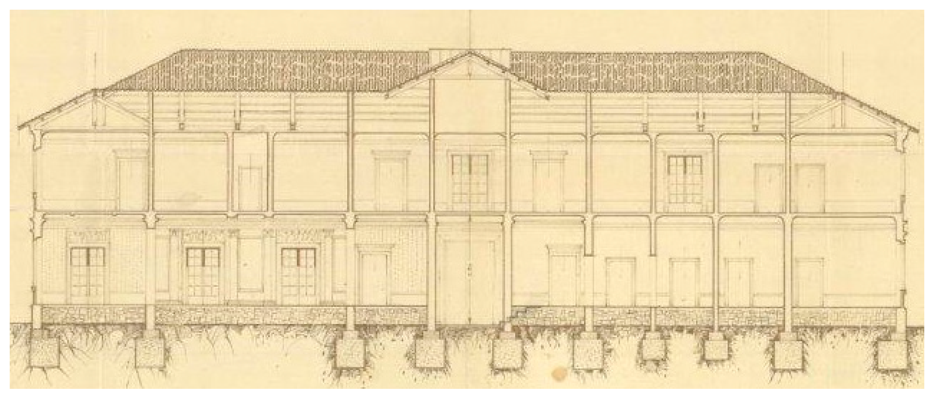
Figure 1. Vertical section from the original drawings.
Buildings 13 02560 g001
Figure 2. Plan of the building with sensors layout. Sensor in () are on the first floor; sensors in [] are in the basement; the other sensors are at the top.
Buildings 13 02560 g002
Figure 3. Power spectral densities at the second floor.
Buildings 13 02560 g003
Figure 4. Cross-spectral densities at the second floor (phase factor in green lines).
Buildings 13 02560 g004
Figure 5. Power spectral densities at the first floor (P1) and the basement.
Buildings 13 02560 g005
Figure 6. Particle motions pairing the sensors in different ways: (a) S17 and S21 are paring with S11 and S15, respectively, while S09 and S13 are paring with S11 and S15, respectively; (b) S17 and S21 are paring with S18 and S23, respectively, while S09 and S13 are paring with S14 and S13, respectively.
Buildings 13 02560 g006
Figure 7. Angle distributions corresponding to particle motions of (a) Figure 6a and (b) Figure 6b.
Buildings 13 02560 g007
Figure 8. Semi-sum and semi-difference time histories of a couple of sensors: (a) S18−S11 and (b) S15–S23.
Buildings 13 02560 g008
Figure 9. Semi-sum and semi-difference time histories of a couple of sensors: (a) S14−S10 and (b) S17–S21.
Buildings 13 02560 g009
Figure 10. Directions that locate the centres of rotation.
Buildings 13 02560 g010
Figure 11. Extruded views of the finite element model.
Buildings 13 02560 g011
Figure 12. First five modal shapes.
Buildings 13 02560 g012
Figure 13. Collapse mechanisms when force distributions are proportional to (a) the first mode and (b) the fourth mode (in green are the elasto–perfect plastic elements).
Buildings 13 02560 g013
Figure 14. Force–displacement curves and corresponding bi-linearized curves (red lines) relative to a force distribution proportional to (a) the first mode and (b) the fourth mode.
Buildings 13 02560 g014
Figure 15. Elements (in red) exceeding seismic demand at SLV (TR = 475 years) for linear analysis: (a) shear for prevalent seismic action along x; (b) axial and flexural forces for prevalent seismic action along x; (c) shear for prevalent seismic action along y; (d) axial and flexural forces for prevalent seismic action along y.
Buildings 13 02560 g015
Figure 16. Elements (in red) exceeding seismic demand when the spectrum corresponding to T R = 140 years is used, for linear analysis: (a) shear; (b) axial and flexural forces for x-directed main seismic component.
Buildings 13 02560 g016
Table 1. Numerical resonance frequencies.
ModeNumerical Frequencies (Hz)
15.22
25.41
35.60
45.83
56.37
67.70
78.60
89.15
99.73
Disclaimer/Publisher’s Note: The statements, opinions and data contained in all publications are solely those of the individual author(s) and contributor(s) and not of MDPI and/or the editor(s). MDPI and/or the editor(s) disclaim responsibility for any injury to people or property resulting from any ideas, methods, instructions or products referred to in the content.