Article

Efficient Finite Element Approach to Four-Variable Power-Law Functionally Graded Plates

by
Gulshan Taj Mohammed Nabi Anwarbasha
1,*,
Anupam Chakrabarti
2,
Alireza Bahrami
3,*,
Vasugi Venkatesan
4,
Abdhullapuram Sachidhanandam Vijay Vikram
5,
Jeyabharathi Subramanian
6 and
Vutukuru Mahesh
7
1
Department of Civil Engineering, Sona College of Technology, Salem 636005, India
2
Department of Civil Engineering, Indian Institute of Technology Roorkee, Roorkee 247667, India
3
Department of Building Engineering, Energy Systems and Sustainability Science, Faculty of Engineering and Sustainable Development, University of Gävle, 801 76 Gävle, Sweden
4
School of Civil Engineering, Vellore Institute of Technology, Chennai 600127, India
5
Global Institute of Engineering and Technology, Melvisharam 632509, India
6
Department of Mathematics, K.S.R. College of Engineering, Tiruchengode 637215, India
7
Department of Mechanical Engineering, SR University, Warangal 506371, India
*
Authors to whom correspondence should be addressed.
Buildings 2023, 13(10), 2577; https://doi.org/10.3390/buildings13102577
Submission received: 14 June 2023 / Revised: 23 August 2023 / Accepted: 4 September 2023 / Published: 12 October 2023
(This article belongs to the Section Construction Management, and Computers & Digitization)

Abstract

:
Many findings and conclusions about the analysis of functionally graded material plates/shells exist in past documents in the literature. Accurate micromechanical modeling of such elements is vital for predicting their responses in different operating environments by virtue of their functional properties along the direction of interest. Applying a single-parameter-dependent law leads to a plate/shell configuration in which the top surface is dominated by the ceramic part, while the bottom surface is occupied by a metal segment. But in actual practice, the situation arises where a designer/analyst should develop a model that incorporates all the possible combinations of the constituents at the top and bottom to meet current demands. In this study, the volume fraction value of a material was governed by a generalized four-parameter law for defining the material profile and incorporating different combinations of profiles. Aluminum/zirconia plates were considered for the study of their mechanics under different support conditions. Different conclusions were derived from this research, and it was perceived that the plate that had symmetric properties with respect to the neutral plane showed better performance than any other profile combinations. Out of the diverse results that are presented, symmetric profiles were recorded as having lower deflection values than those of the other profiles adopted in the study.

1. Introduction

The reasons to opt for functionally graded material (FGM) structures over other conventional types of structures (isotropic/laminated composites) are well explicated in many past research documents [1,2,3,4,5,6,7,8,9]. In this regard, many classical and modern approaches that incorporate various solution strategies have been established for the analysis of such structures under different loading conditions. The finite element method (FEM) [10,11,12,13,14,15,16,17,18,19,20,21,22,23,24,25,26], differential quadrature method (DQM) [27,28,29,30,31,32,33,34,35,36,37], and mesh-free collocation radial basis approaches [38,39,40,41,42,43,44,45] are a few of the solution tools that have been the most widely adopted by many researchers. Even though each method has its own conduit for handing the problem of interest, the major conclusions attained from such approaches on the responses of FGM structures lead along an identical path. Many fields of kinematics based on classical plate theory (CPT) [46,47,48,49,50], first-order shear deformation theory (FSDT) [2], and higher-order shear deformation theory [11,51,52,53,54] have been considered to establish strain–displacement relations and to arrive at the governing equation of an analysis. But to accurately predict the various quantities, e.g., displacement and in-plane and shear stresses, terms with higher degrees should be incorporated into the displacement expression [55]. Current research work incorporated fields of kinematics that consist of cubic and quadratic deviations of thickness in the in-plane and transverse displacement fields, respectively. Hence, in this work, the overall response of a plate was established while considering the transverse and normal deformation components to incorporate extension-bending coupling. The higher-order theory proposed by Reddy [56] does not demand shear correction in numerical calculations. No stress boundary conditions are applied to solve for unknown higher-order terms present in the displacement fields. While doing so, the first order-based derivatives of the in-plane and transverse displacement expression turn into second-order derivatives in the corresponding strain field components. The above situation leads to the formulation of the C1 continuity problem and the difficulties associated with it. Also, in most practical cases, C0 elements are preferable to C1 elements, as they result in easy iso-parametric formulation. Hence, in this research, the derivative of the transverse displacement was treated as an independent variable, thus leading to an accurate yet simple finite element formulation.
Sometimes the situation arises in which a component of a structure should sustain ultra-high temperatures without compromising its structural integrity or experiences large temperature gradients within a fraction of seconds. In such cases, a mixture of two distinct materials that satisfy the design requirements is the best choice overcoming this issue. Ceramic is a material that has a high stiffness with low coefficients of thermal conductivity and thermal expansion. On the other hand, metal offers high thermal expansion and high thermal conductivity with a low stiffness. An appropriate application of these two materials (ceramic and metal) would perform in a better way under such circumstances. In a typical situation, FGM structures are manufactured in such a way that smooth and gradual variations in the material properties are ensured at every point. Such an option for modeling eliminates the material and geometric discontinuities observed in conventional composite laminates (matrix de-bonding, splitting of bonding between adjacent layers, high stress concentrations at layer interfaces, etc.). Although one’s perception could be extended in the x, y, and z directions, many studies preferred to apply this concept in the direction of the thickness (for example, [1,2,5,7,25]). Fewer studies in the literature utilized the concept in two/three directions [57,58,59,60,61,62]. In order to accurately capture the particle distribution in FGM, many methods have been proposed in the literature. The power law function [63], sigmoid-based function [64], and exponential-based function [65] are few functions that exist in the literature. Most of the research works reported so far have used the power gradient law function [63]. The general function adopted in the literature leads to ceramic plate (isotropic) in the upper portion and a metal plate (isotropic) in the lower portion, and the intermediate portion is defined by a combination of the two materials that obeys a simple power law. But there is a demand for a configuration other than this general one due to the influence of some physical parameters. To propose an alternative solution, a general power law function in which different combinations of material profiles are possible should be established. From this point of view, a notable contribution was made by Tornabene and his associates [27,28,37,66]. From the design perspective, the expression of a power law distribution incorporating four variables can be effectively employed to control the vibration and deflection response of a plate/shell. Hence, the authors intended to perform a mechanical analysis of FGM plates by using a four-parameter-dependent power law function [27]. Different FGM configurations are possible by the right selection of parameters (four in this research) present in the power law function. It is worth mentioning that a designer/researcher can achieve any combination of material profiles with a suitable choice of parameters. Tornabene [27] investigated the extraction of natural frequencies of different plate and shell structures for diverse geometrical cases. Among the different parameters considered, it was concluded that the choice of the power law distribution had a marked influence on the frequency, especially for the cases of cylindrical and conical panels. As a further extension, a power law function was utilized to understand the vibration of parabolic panels made of FGMs [28]. Instead of four parameters, the power law function was represented by three parameters that dictated the material distribution profile along the z direction. Combinations of many profiles can be proposed in the cases of both types of analyses (four-parameter power law distribution and three-parameter power law distribution) provided that the volumetric criteria between ceramic and metal are satisfied. The FSDT-based Gaussian differential quadrature (GDQ) method was extended to understand the vibration (free) of FGM parabolic shells by Tornabene and Viola [66]. Different mode shapes were considered for toro-parabolic and parabolic panels based on a four-term-dependent power law function. Diverse material configurations were selected to establish the frequency parameters of different panel types. Yasandaragh [67] used a four-parameter power law for free-vibration problems of sandwich panels with an FGM as the core and a fiber-reinforced composite arrangement in the bottom layers. The fiber orientations of face sheet layers were displayed by a four-parameter power law function, and the GDQ method was employed. Classic and other profiles were established for different cases of the fiber orientations and core types. They observed lower frequency values for the sandwich panels than the frequency values of orthotropic face sheets. More recently, Tornabene and Viola [37] analyzed doubly curved shells as an extension of their earlier work. The GDQ method in general form was applied for the derivation of differential equations in discrete form. Stresses were recovered from 3D elasticity solutions, and the displacement variations shed light on FSDT of Toorain and Lakis [68]. Different material profiles were demonstrated with the appropriate selection of four parameters to represent the stresses of doubly curved shells with different geometries. Other relevant research works included the application of a variable separation method for FGM plates by Vidal et al. [69]; an analysis of FGM plates/shells [70] in a nonlinear sense that motivated many young researchers to perform numerous related studies. In addition, optimization studies of FGM cylinders and other geometrical shapes were performed by many researchers [71,72,73,74,75,76], and diverse approaches were implemented. Vinh et al. [77] analyzed the static and buckling responses of bi-directional FGM plates with a porous configuration by utilizing an improved FSDT along with the concept of FEM. The porosity of the plates reduced their rigidness; thus, a high value of deflection was recorded. Prior to those studies, Salari et al. [78] and Priyanka et al. [79] examined the influence of the parameters, temperature and porosity, on the stability and dynamic behavior of FGM beams. Keleshteri et al. [80] investigated the nonlinear response of porous FGM beams in vibration by incorporating a bi-direction nature. Microtube FGMs in a nonlinear environment and their responses, which included porosity, were examined by Xiaohuan et al. [81]. Other relevant works in the area of FGM include studies related to hydrothermal effects and a few new theories [82,83]. In addition, many researchers made their research footprint by considering FGM nanoplates [84,85]. However, in this study, the influence of porosity was not considered because the scope of the study was limited to material variation and displacement patterns.
The significant properties offered by FGMs, such as their high load-carrying capacity due to the coupling between the membrane and flexural part and their high degree of anisotropy, require researchers/analysts to formulate a theory in which the transverse and normal stress components are considered to address the issues related to existing theories in the literature (for example, CPT and FSDT). All studies concerning the current topic employed FSDT, and the transverse shear effect was calculated in a linear sense by incorporating a correction factor for the shear to compensate for the scarcity of results. Hence, to bridge the gaps observed in FGM research, an analysis was performed by considering various material profile combinations. Variation in the transverse displacement component was kept constant, and the similar variations are available in other literature studies [27,28,37]. The Lagrangian element with nine nodes used by the authors [25,26] for static and dynamic analyses was extended in this study. Three types of profiles, i.e., classical, symmetric, and asymmetric, were chosen to provide the results, in addition to other profile combinations. Stress patterns in the direction of the thickness are shown in the form of graphs for different combinations of materials and power law profiles. To summarize, this research article presents sections and subsections on modeling of plates/shells; thereafter, numerical investigations are described and discussed in detail. Finally, the significant interpretations and observations obtained from the research are highlighted in the last section.

2. Problem Description and Modeling

2.1. Modeling of Plates

A linear elastic rectangular FGM of dimensions a × b × h (plate geometry) was modeled for the study. Cartesian coordinates (x, y, and z) with z = 0 were assumed as the neutral plane. The plate geometry was modeled with a nine-node isoparametric element that consisted of thirteen nodal unknowns corresponding to each node in the configuration. The FGM plate comprised aluminum as ceramic and zirconia as metal, and this was modeled and employed for the purposes of the investigation. An effective material property varies in the z direction in a gradual and continuous manner and is described by the following distribution:
P ( z ) = P c P m V c + P m
where the subscript notations displayed by c and m denote ceramic and metal, respectively, with the letter V for the volume fraction. The material properties at any point depend on Young’s modulus (E), density (ρ), thermal conductivity (k), and thermal expansion (α), and they follow Equation (1). Young’s modulus (E) needs a homogenization process, and a constant magnitude of Poisson’s ratio of 0.3 was assumed. Vc in Equation (1) assumes the following form of a four-variable expression:
F G M I / F G M I I ( a / b / c / n ) : V c = 1 a 0.5 ± z h + b 0.5 ± z h c n
where a, b, and c denote the material profile, and the term n is used to designate the material gradient index in this research. It varies between 0 and infinity and characterizes the ceramic part and metal portion, respectively. Any intermediate values indicate the composite plate with a smooth variation in functional parameters. In the present case, parameters a, b, c, and d were chosen to achieve classic, symmetric, and asymmetric profiles. Even though each case leads to a distinct plate configuration, differences between the results (either deflection or frequency) for the different cases were noticed after the fourth decimal [27]. Henceforth, with the intention of providing significant results, the authors opted to perform the current analysis. Users can assign different values to material parameters to obtain the plate configuration that results in isotropic/graded properties in the top/bottom/intermediate segments. In this research, the parameters were chosen in such a manner that the FGM plate demonstrated classical, symmetric, and asymmetric profiles. However, the values picked for the parameters should lead to the expression Vc so that Vc + Vm = 1. In this study, the FGMII plate geometry was employed by assigning the values for a, b, c, and n.
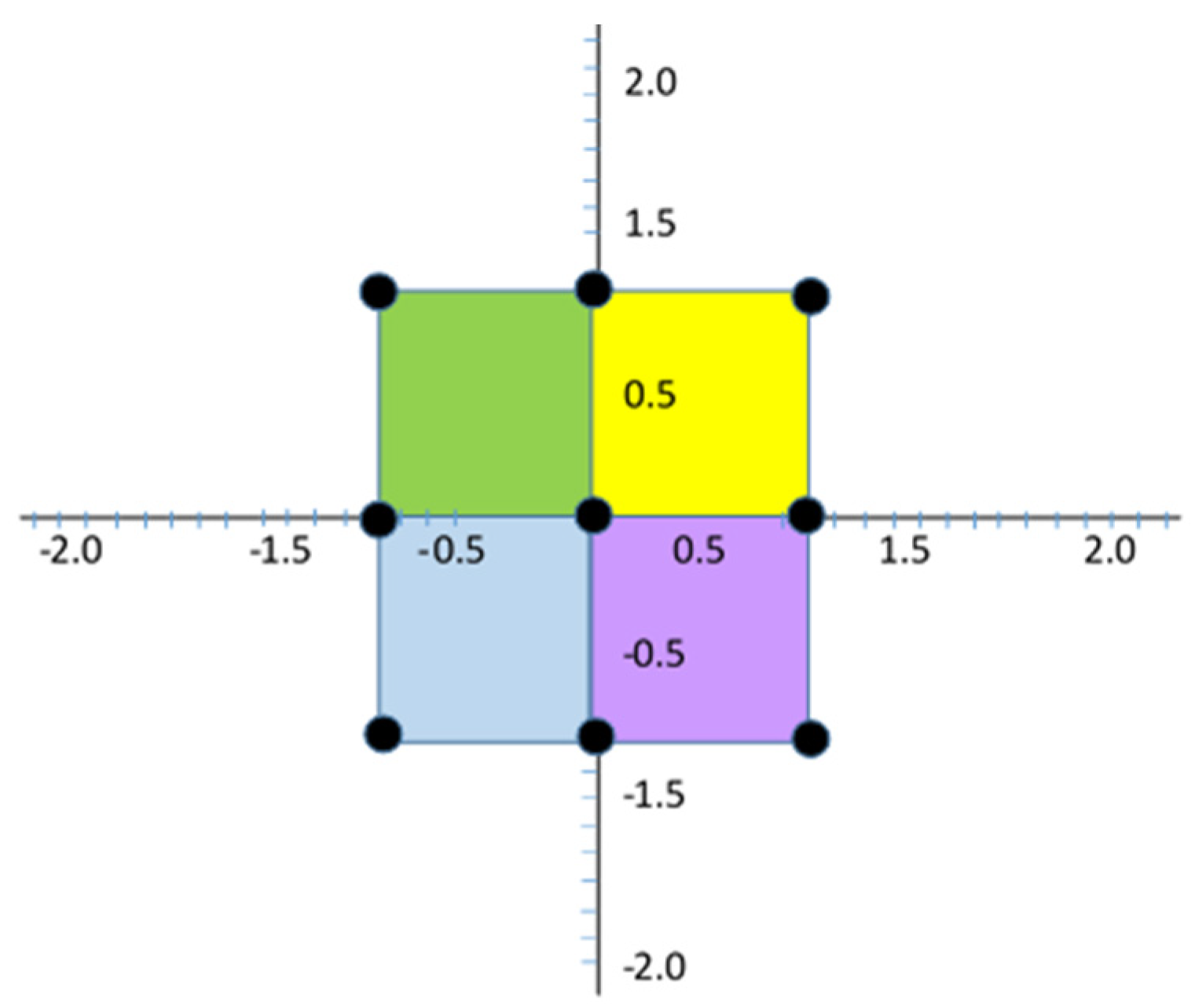
Typically, a classical FGM plate comprises two kinds of materials that are dissimilar in nature—usually ceramic and metal; the upper and lower segments are represented by ceramic and metal, respectively. Since this analysis was formulated with a power law model that had four parameters in the expression, it was possible to model the plate with any combination of isotropic/composite plates at the top/bottom. The employed FGM plate is depicted in Figure 1 and Figure 2. The FEM study was conducted using nine-node isoparametric element formulation. A skyline storage scheme with banded element storage was deployed during the analysis stage.
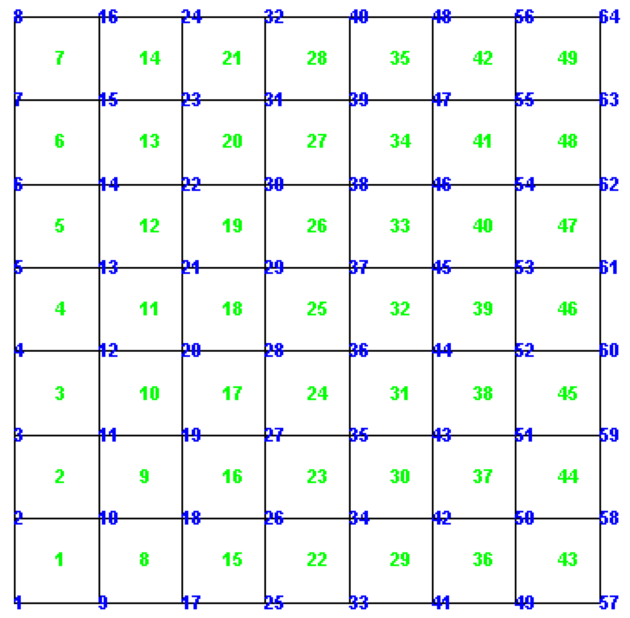
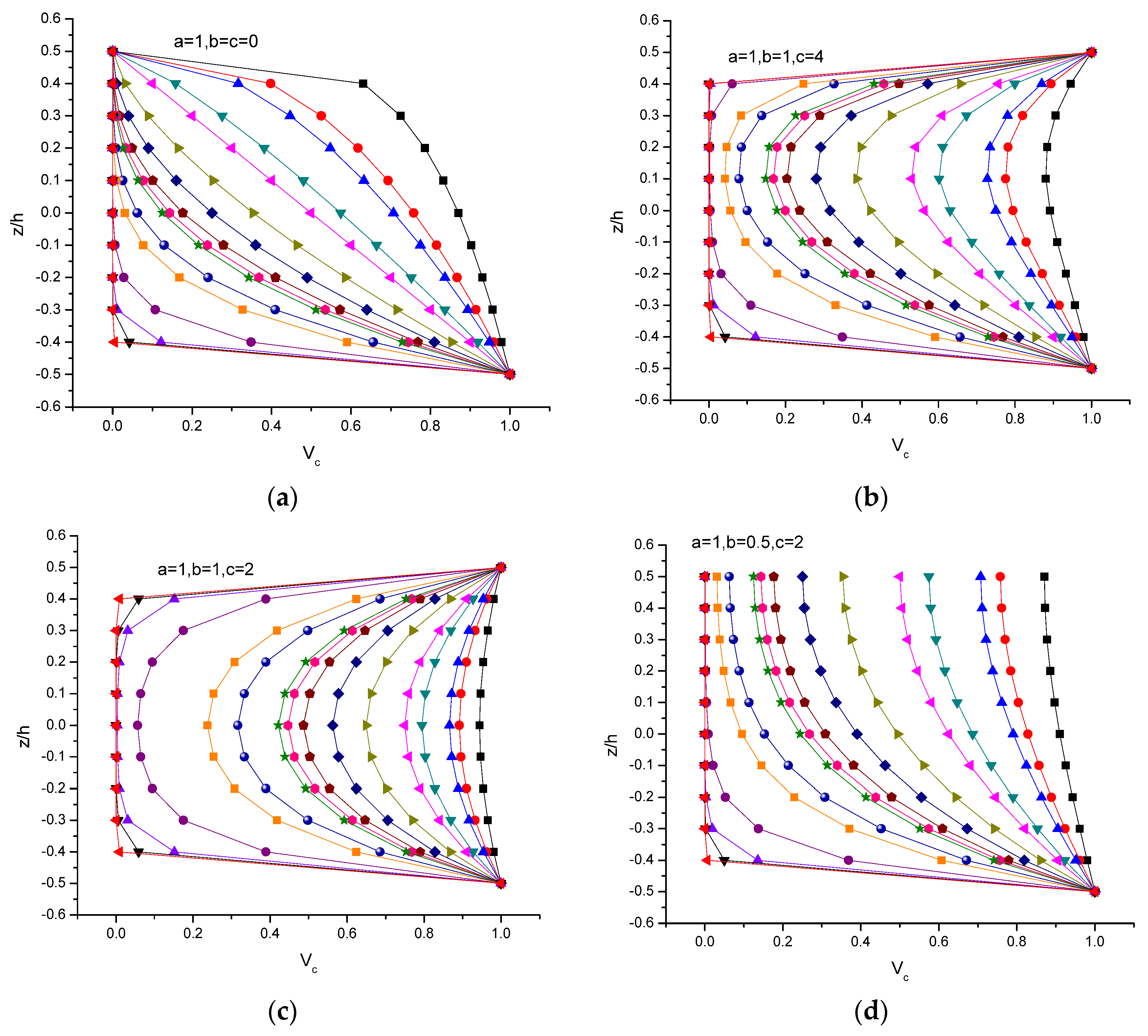
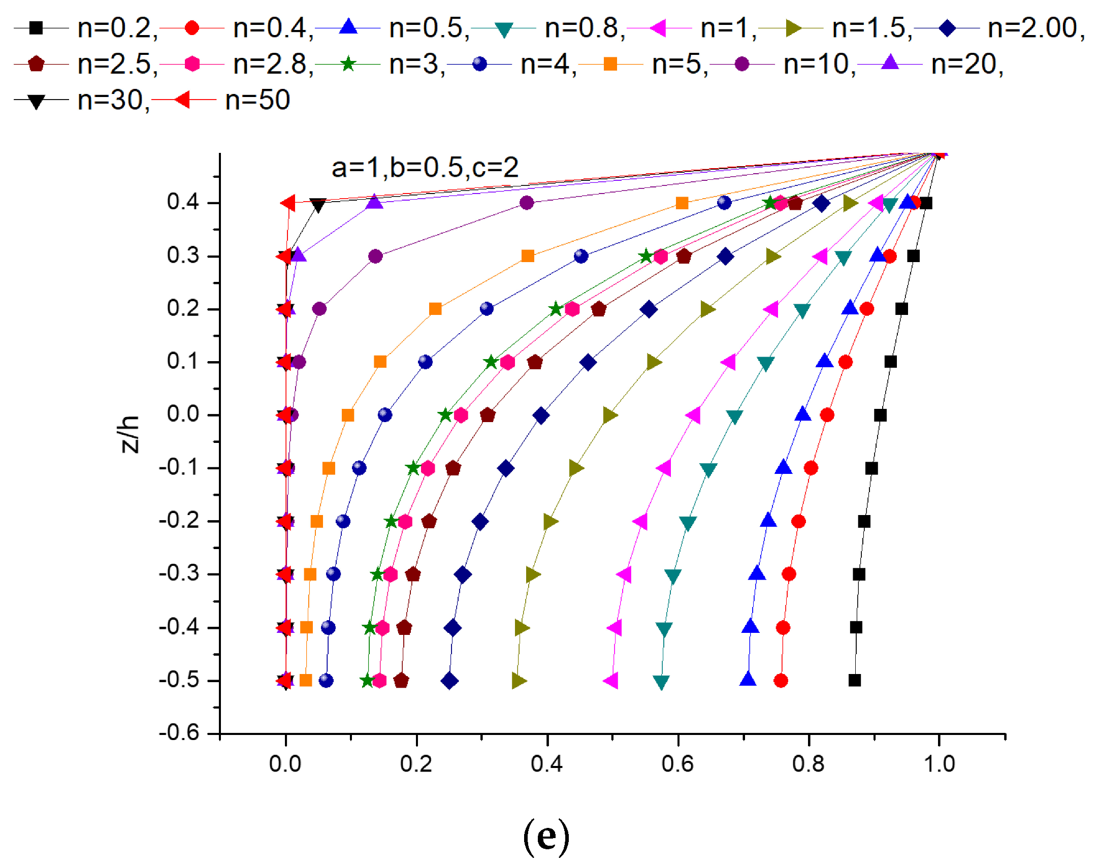
The meshing that was done for the plate geometry and the node-numbering configurations are illustrated in Figure 3. The different material profiles obtained from the four-parameter power law distribution by assuming suitable parameters are depicted in Figure 4a–e. The classical profile (Figure 4a), i.e., the most general one shown by many researchers [6,7], was governed by adopting a value equal to 1 and setting b and c to 0. With this option, the top and bottom of the plates became pure ceramic and pure metal, respectively. The asymmetric (Figure 4b) and symmetric profiles (Figure 4c) were achieved by assuming another set of values for parameters a, b, and c (a and b held values of 1 and c was equal to 4 for the asymmetric profile, and a = b = 1 and c = 2 for the symmetric profile). Although both of these profiles involved ceramic at the top and bottom of the plate, the latter case exhibited an anti-symmetric nature with respect to the neutral plane. Further, beyond a certain value of the material gradient parameter, i.e., n = 20, a linear variation (in a partial sense) in the ceramic distribution was noticed. As the material gradient index increased, the graded plate entered the isotropic zone, thus exhibiting a linear variation. Figure 4d,e indicate the material profiles in which the top portion was represented by ceramic, and the lower portion was represented by constituents of ceramic and metal in equal proportions, and vice versa. Hence, it is noteworthy that the current power law distribution depended on four parameters, which might provide details about several combinations of FGM profiles of interest. Also, from the design viewpoint, it is essential to verify that the bottom and top portions are rich in ceramic/metal, and the intermediate portion indicates combination of ceramic and metal.

2.2. Kinematic Field

In the current displacement field, the components u, v, and w were incorporated, and their quadratic and cubic variations were included in the following expression:
u ( x , y , z ) = u o ( x , y , z ) + z θ x ( x , y , z ) + z 2 ξ x ( x , y , z ) + z 3 ρ x ( x , y , z ) v ( x , y , z ) = v o ( x , y , z ) + z θ y ( x , y , z ) + z 2 ξ y ( x , y , z ) + z 3 ρ y ( x , y , z ) w ( x , y , z ) = w o ( x , y , z ) + z ζ z ( x , y , z ) + z 2 ξ z ( x , y , z )
where notations with o as subscripts denote mid-plane displacement variations corresponding to three primary axes (x, y, and z). Rotations due to bending about the two primary axes (x and y) are designated by θx and θy, respectively. The polynomial functions connected with the quadratic and cubic terms in the in-plane and transverse field—Taylor’s higher-order terms—are used to consider the variations in the shear deformation in the z (thickness) direction. To resolve this, higher-order polynomial components with no stress boundary conditions (i.e., τxz = τxz = 0 at z = ±h/2) were employed. When these boundary conditions were imposed, Equation (3) turned into Equation (4).
u ( x , y , z ) = u o + z 4 z 3 3 h 2 θ x z 2 2 ζ z x 4 z 3 3 h 2 w 0 x z 3 3 ξ z x v ( x , y , z ) = v o + z 4 z 3 3 h 2 θ y z 2 2 ζ z y 4 z 3 3 h 2 w 0 y z 3 3 ξ z y
The strain expression developed here ensures the survival of second order-based derivatives of the transverse displacement in the expression due to the first-order derivatives in Equation (4). In most practical applications, C0 elements are preferred over C1 elements because of their easy isoparametric formulation. Hence, in order to develop a C0 formulation, out-of-plane derivatives were exchanged by independent-field nodal entities.
Thus, the concluding derivation denoting the kinematic field (u, v, and w) contained C0 variables and was:
u ( x , y , z ) = u o + z 4 z 3 3 h 2 θ x z 2 2 α x 4 z 3 3 h 2 β x z 3 3 ψ x v ( x , y , z ) = v o + z 4 z 3 3 h 2 θ y z 2 2 α y 4 z 3 3 h 2 β y z 3 3 ψ y w ( x , y , z ) = w o + z ζ z + z 2 ξ z
The displacement vector contains terms such as d =   u 0 , v 0 , w 0 , θ x , θ y , ζ z , α x , α y , ξ z , β x , β y , ψ x , ψ y T for all the available nodes. A 117-node Lagrangian element with nine nodes in each element was incorporated in this study. The elements were free from locking and spurious modes that occur during the formulation. Shape function expressions are dependent on natural coordinates, and their variations are graphically illustrated in Figure 5.
For the corner nodes:
N 1 = 1 4 ξ 1 η 1 ξ η , N 3 = 1 4 ξ + 1 η 1 ξ η , N 7 = 1 4 ξ 1 η + 1 ξ η , N 9 = 1 4 ξ + 1 η + 1 ξ η
For the mid-side nodes:
N 2 = 1 2 1 ξ 2 η 2 η , N 4 = 1 2 ξ 2 ξ 1 η 2 , N 6 = 1 2 ξ 2 + ξ 1 η 2 , N 8 = 1 2 1 ξ 2 η 2 + η
For the center node:
N 5 = 1 ξ 2 1 η 2
For the generic node present in the mid-plane, the displacement variation is denoted as:
u i = i = 1 N N N i ξ , η i d i
where all the terms assume their regular meanings; for further explanation, readers can refer to the other research performed by the authors [25,26].
The strain components can be expressed as:
ε x x = u x ; ε y y = v y ; ε z z = w z γ x y = u y + v x ; γ x z = u z + w x ; γ y z = v z + w y
By substitution of the terms from Equation (3) into Equation (7), the strain and displacement components can be combined.
ε x x = u o x + z 4 z 3 3 h 2 θ x x z 2 2 α x x 4 z 3 3 h 2 β x x z 3 3 ψ x x ε y y = v o y + z 4 z 3 3 h 2 θ y y z 2 2 α y y 4 z 3 3 h 2 β y y z 3 3 ψ y y ε z z = ζ z + 2 z ξ z γ x y = u o y + v o x + z 4 z 3 3 h 2 θ x y + z 4 z 3 3 h 2 θ y x z 2 2 α x y z 2 2 α y x 4 z 3 3 h 2 β x y 4 z 3 3 h 2 β y x z 3 3 ψ x y z 3 3 ψ y x γ x z = 1 4 z 2 h 2 θ x z α x 4 z 2 h 2 β x z 2 ψ x + w o x + z ζ z x + z 2 ξ z x γ x y = 1 4 z 2 h 2 θ y z α y 4 z 2 h 2 β y z 2 ψ y + w o y + z ζ z y + z 2 ξ z y
Note that the above equation contains a displacement component with single-order transverse component, thus resulting in an efficient C0 formulation. The strains appearing in Equation (8) are compensated by the strains in the general order via subsequent manifestations.
ε ¯ 6 x 1 = H 6 x 20 ε 20 x 1
where ε ¯ 6 x 1 = ε x x ε y y ε z z γ x y γ x z γ y z
ε 20 x 1 = u o x , v o y , ζ z , w o y + θ y , w o x + θ x , u o y + v o x , θ x x , θ y y , ξ z , ζ z y + α y , ζ z x + α x , θ x y + θ y x , α x x , α y y , θ y + ξ z y + β y + ψ y , θ x + ξ z x + β x + ψ x , α x y + α y x , θ x x + β x x + ψ x x , θ y y + β y y + ψ y y , θ x y + β x y + ψ x y + θ y x + β y x + ψ y x T
The components of matrix [H] of order 6 × 20 contain functions that are linear and cubic in nature, and they are dictated in the following fashion:
H = [ 1 0 0 0 0 0 z 0 0 0 0 0 z 2 0 0 0 0 z 3 0 0 0 1 0 0 0 0 0 z 0 0 0 0 0 z 2 0 0 0 0 z 3 0 0 0 1 0 0 0 0 0 z 0 0 0 0 0 0 0 0 0 0 0 0 0 0 1 0 0 0 0 0 z 0 0 0 0 z 2 0 0 0 0 0 0 0 0 0 1 0 0 0 0 0 z 0 0 0 0 z 2 0 0 0 0 0 0 0 0 0 1 0 0 0 0 0 z 0 0 0 0 z 2 0 0 z 3 ]

3. Investigation of Numerical Problems

An efficient C0 formulation incorporating the finite element analysis was developed in a MATLAB environment in this research work. An FGM plate demonstrating a generalized four-parameter based power equation for defining the material’s dissimilarity in the direction of the thickness was modeled with an aluminum/zirconia profile. To achieve concise and significant results, classical, symmetric, and asymmetric profiles were considered when performing the numerical investigations. Each configuration was a subcategory of the generalized power law formulation and was obtained via the appropriate selection of material profile parameters in Equation (1). The material variation/gradient parameter (n) was chosen to represent the isotropic and composite cases of plate geometry, and its influence on the bending behavior was established. Generated results were validated with the results available in literature for static, buckling, and dynamic analyses by assuming various cases of FGM skew plate/shell configurations. Details of the convergence and validation exist in [25,26]. Five combinations pertaining to the material parameters were incorporated to arrive at a specific FGM model (Table 1). The assumed properties of the materials and material combinations were Ec = 151 × 109 N/m2, ρc = 3000 kg/m3, kc = 204 W/(mK), αc = 23 × 10−6 1/K, Em = 70 × 109 N/m2, ρm = 2707 kg/m3, km = 2.09 W/(mK), and αm = 10 × 10−6 1/K. Poisson’s ratio was assumed to be 0.3 for both materials. The results are generally described as non-dimensional quantities in the proposed investigation. The non-dimensional parameters for the central deflection, load, and thickness coordinates were w ¯ = w h , q o = q E m h 4 , and z ¯ = z h .
To demonstrate the consequences of the parameters (a, b, and c) for the volume parameter distribution of the ceramic segment, Vc, different combinations of the material parameters were chosen, as listed in Table 1. The numerical parameters were taken in such a manner that the most general configurations could be chosen for an appropriate illustration. A magnitude of the material gradient index n of 0.2 was chosen to start with, and it was increased to 50 to indicate the distribution of the metal and ceramic constituents. The classical material variation profile was added to every numerical example to allow the reader to better visualize other material combinations. Among the different profiles presented, the distribution displayed a linear variation for homogeneous plates, i.e., when n approached 0.2 and 50 (implying high volume fraction with respect to the isotropic material). Further, intermediate values showed a nonlinear distribution, and the nature of the nonlinearity progressively diminished when the isotropic zone was considered. Profiles other than those illustrated in Figure 4a–e are possible, provided that the volumetric relationship has been taken care of during the parameter selection.
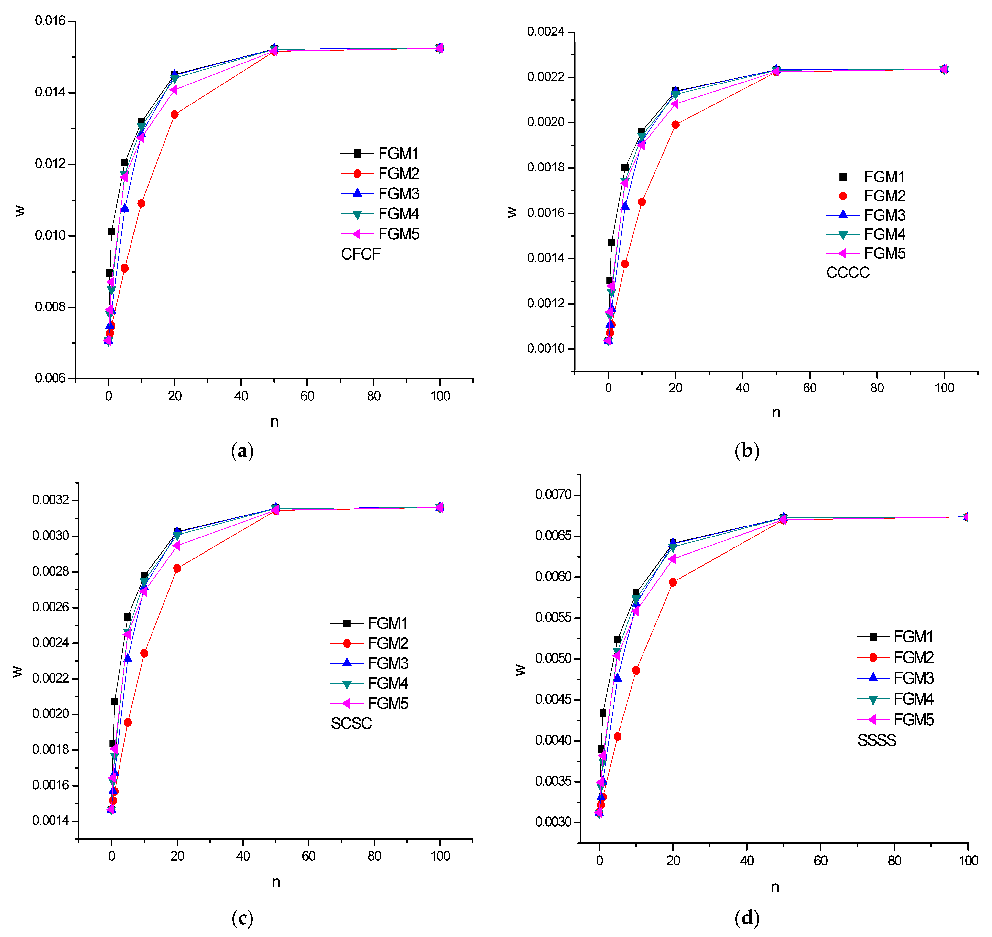
Out of the different support conditions (Figure 6a–d) considered in this study, the plate with clamped edges was found to have the minimal deflection for various values of the material gradient index. Different FGM models exhibited the same magnitude of deflection for a lower magnitude of material variation with n values of 0, 0.5, 1, and 5. Further escalation in the n value tended to elevate the deflection value and lay in an unstable mode beyond n = 50. As the value of n was elevated, the material variations gently diminished, i.e., the plate contained a high percentage of isotropic material. Among the various profiles depicted, symmetric profiles were considered to be superior compared to classical and asymmetric profiles due to low deflection values. Except for the FGM2 model, all the chosen models indicated no significant divergence in their behavior, and this trend was found to be marked when n ranged from 5 to 50.
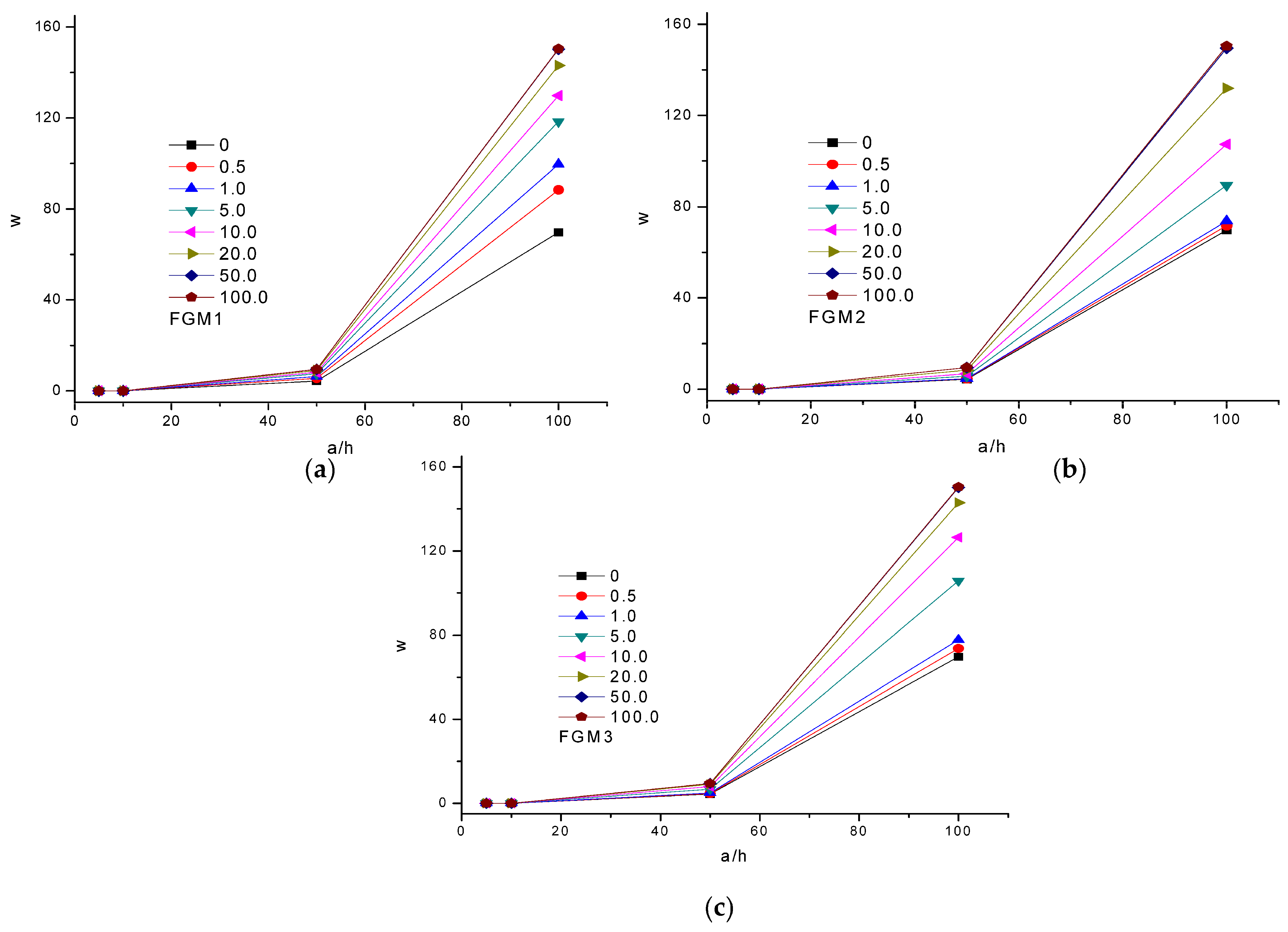
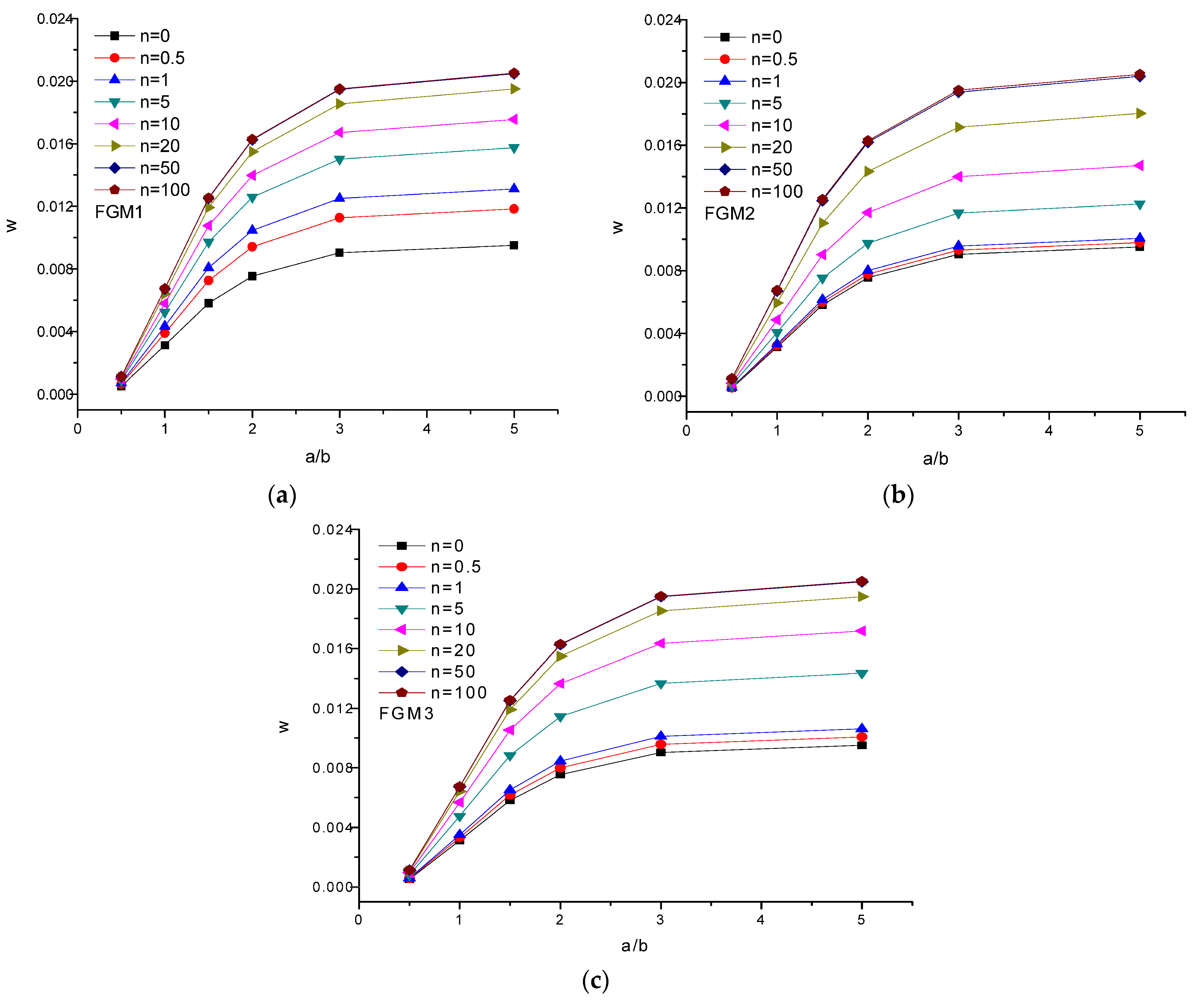
Variation in the transverse displacement w and contour for the FGM plates when subjected to in-plane loading conditions are depicted in Figure 7. The maximum value for the displacement was visualized at the center, and it gradually diminished toward the edges, which confirmed the common displacement pattern. To reveal the influence of the factor a/h on deflection, three categories, namely, FGM1, FGM2, and FGM3, were considered with several ranges of n values (i.e., n = 0 to 100) (Figure 8a–c). It was noticed that when thick plates were considered, there was no significant progress in deflection, i.e., it was negligible. Variation in deflection was observed to be drastic for the thin models, and this fact was identical for all the FGM models under consideration. Once again, the symmetric profiles revealed lower deflection values compared to asymmetric and classical profiles. In addition, a parametric study was conducted to determine deflection versus aspect ratio (a/b) while including different material gradient indexes (Figure 9a–c). Parameter b was kept constant, while a was varied from the value of 0.5 to nearly 5. The curves representing the material gradient value did not reflect much disparity with respect to the deflection response for a lower aspect ratio, and they illustrated a gradually increasing trend as the aspect ratio became greater than 0.5. An asymptotic response was manifested when the length was three times the width. Except in the FGM1 model, the plate containing the lowest percentage in the volume fraction of ceramic/metal did not depict any marked response for various values of a/b. For the three cases in Figure 9a–c, the FGM plate with n = 100 provided the maximum deflection intensity because less of a stiffening effect was offered by the corresponding plate.
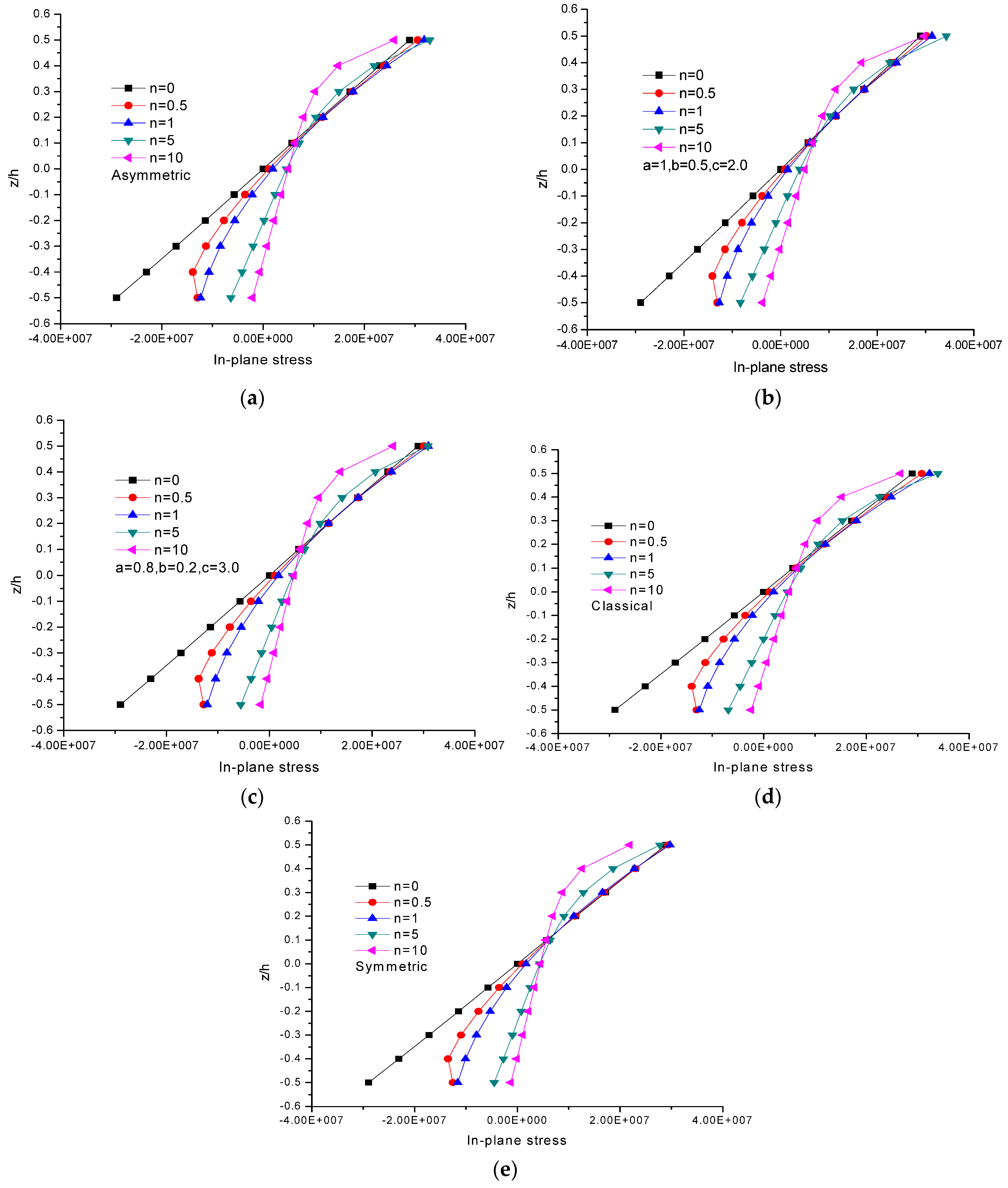
After the completion of the aforementioned numerical investigations, an analysis of the variations in stresses in the direction of the thickness was done. A linear stress distribution σxx is displayed in Figure 10a–e, while a transformation in the behavior occurred as the n value reached 5. The compressive and tensile stresses were nonlinear in nature, and it was noticed that as n reached an intensity of 10, the stress values tended to be low in magnitude. The existence of a significant percentage of the ceramic and metal components was the primary controlling factor. In addition, the volume fraction index was another controlling factor for defining the geometry of the plate and, thus, the response of the plate in static and dynamic environments. Out of the many studied configurations, the FGM5 plate exhibited the maximum tensile and compressive stresses when assuming various n values.
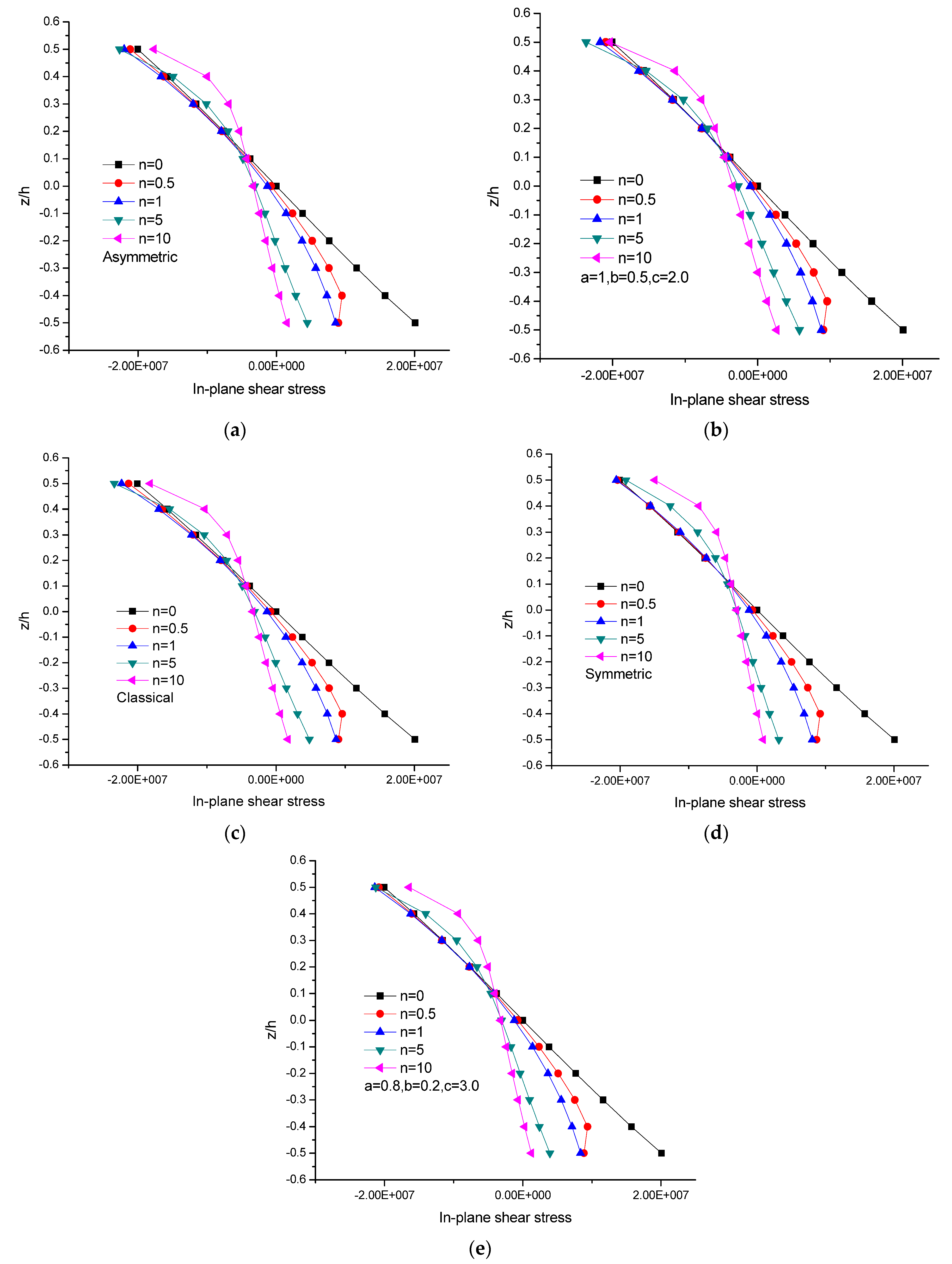
The disparity of the in-plane shear stresses and transverse shear stresses in the xy direction is revealed in Figure 11a–e and Figure 12a–e, respectively. The stresses for the n values ranging from 0, 0.5, 1, 5, to 10 are shown in the graphical form. Out of the many results generated, the lowest value of the stress was observed for the symmetric profile.
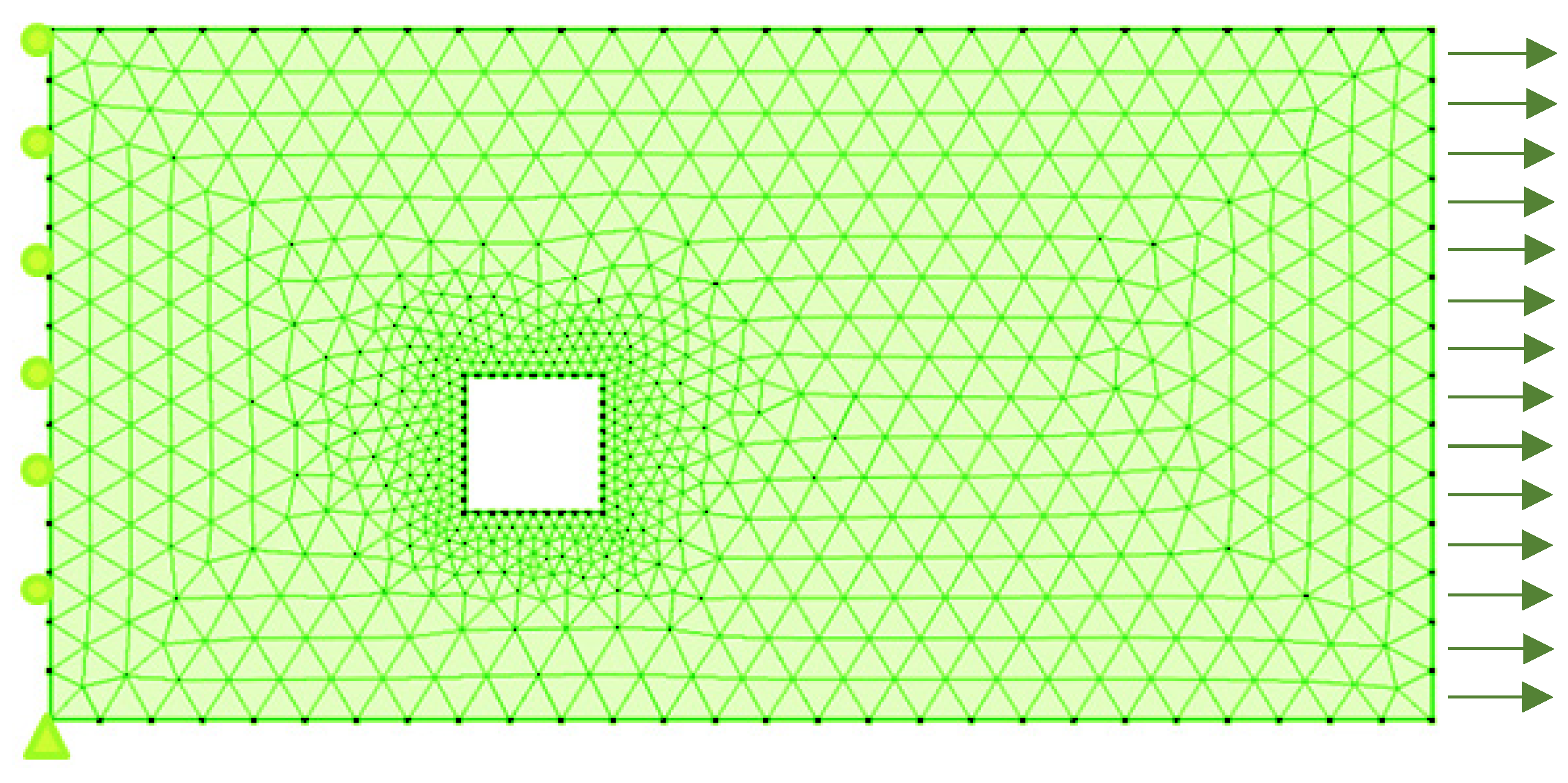
It is well known that the phenomenon of singularity occurs due to sharp reentrant corners in plates (Figure 13). As far as tress singularities are concerned, reentrant corners are a common situation in finite element analysis. However, careful analysis by an expert to find the possible locations of singularities and to study the effects on the modeling phase can result in an efficient algorithm. A rectangular FGM plate with a size of 3 × 1 m and a cutout of size 0.25 m was subjected to pure tension (Figure 14) for a numerical study. It was observed that as the mesh refinement happened, the stress at the point of interest kept on elevating, and the pattern was constant in all the cases. The localization of the stress field occurred closer to the hole. In such cases, it is recommended to eliminate the singularity problems in error estimates with adaptive meshing cases.

4. Conclusions

In this study, a 2D plate model incorporating C0 continuity was presented using nine-node Lagrangian element. A generalized power law distribution that contained four variables, known as the material gradient parameters, was employed to define the dissimilarity profile in the z direction. Symmetric and asymmetric profiles were incorporated into the numerical part by making a suitable choice of the four parameters. The results obtained for the bending analysis were compared to those of the classical profile to display the effectiveness of the study. The key conclusions from this investigation are summarized below.
  • A generalized power law variation led to different combinations of FGM constituents by means of appropriate choices of the material gradient parameters.
  • Different FGM models incorporating various boundary conditions demonstrated marked bending responses for n > 5. Further, an asymptotic response was ensured when n reached a value greater than 50.
  • It was witnessed that symmetric plates exhibited lower material gradient values, which, in turn, did not play a primary role in dictating the deflection parameter when the aspect ratio was varied.
  • Linear axial stress variations in the x direction were noticed for isotropic and graded plates, and the trend was not obvious when n assumed the numerical value of 10. Also, the neutral plane shifted toward the bottom segment of the plate when n approached 10 and remained unchanged.
  • A marked response was seen in the isotropic and graded FGM plates in the case of axial stress variations in the y direction, and this response was considerable in the bottom segment.
  • The graded plate illustrated a noticeable response on par with that of the isotropic plates. The magnitudes of the tensile and compressive stresses were identical for the isotropic case, which was not true in the case of the graded plate.
  • In all the cases, symmetric profiles were a better choice than other profiles for minimizing the deflection of the plate.
  • As the mesh underwent refinement, the stress values tended to be elevated at the reentrant corners, which was a common observation.
  • Based on the achieved results, the generalized power law containing four parameters provides structural designers with a flexible approach for multiple requirements.

Author Contributions

Conceptualization, G.T.M.N.A., A.C. and A.B.; methodology, G.T.M.N.A., A.C. and A.B.; validation, G.T.M.N.A., A.C., A.B., V.V., A.S.V.V., J.S. and V.M.; formal analysis, A.B.; investigation, G.T.M.N.A., A.C., A.B., V.V., A.S.V.V., J.S. and V.M.; resources, A.B.; writing—original draft preparation, G.T.M.N.A., A.C., A.B. and V.M.; writing—review and editing, G.T.M.N.A., A.C., A.B. and V.M. All authors have read and agreed to the published version of the manuscript.

Funding

This research received no external funding.

Data Availability Statement

Not applicable.

Conflicts of Interest

The authors declare no conflict of interest.

References

  1. Praveen, G.N.; Reddy, J.N. Non-linear transient thermo elastic analysis of functionally graded ceramic-metal plates. Int. J. Solids Struct. 1998, 35, 4457–4476. [Google Scholar] [CrossRef]
  2. Reddy, J.N. Analysis of functionally graded plate. Int. J. Numer. Methods Eng. 2000, 47, 663–684. [Google Scholar] [CrossRef]
  3. Vel, S.S.; Batra, R.C. Exact solution for thermo elastic deformation of functionally graded thick rectangular plates. J. Am. Inst. Aerosp. Astrol. 2002, 40, 20–24. [Google Scholar]
  4. Qian, L.F.; Batra, R.C.; Chen, L.M. Static and dynamic deformations of thick functionally graded elastic plates by using higher-order shear and normal deformable plate theory and meshless local Petroc-Galerkin method. Compos. Struct. Part B 2004, 35, 685–697. [Google Scholar] [CrossRef]
  5. Zenkour, A.M. Generalized shear deformation theory for bending analysis of functionally graded plates. Appl. Math. Model. 2006, 30, 67–84. [Google Scholar] [CrossRef]
  6. Lee, Y.Y.; Zhao, X.; Liew, K.M. Thermo elastic analysis of functionally graded plates using the element free kp-Ritz method. Smart Mater. Struct. 2009, 18, 035007–035022. [Google Scholar] [CrossRef]
  7. Talha, M.; Singh, B.N. Static response and free vibration analysis of FGM plates using higher order shear deformation theory. Appl. Math. Model. 2010, 34, 3991–4011. [Google Scholar] [CrossRef]
  8. Woodward, B.; Kashtalyan, M. 3D elasticity analysis of sandwich panels with graded core under distributed and concentrated loadings. Int. J. Mech. Sci. 2011, 53, 872–885. [Google Scholar] [CrossRef]
  9. Jha, D.K.; Tarun, K.; Singh, R.K. A critical review of recent research on functionally graded plates. Compos. Struct. 2012, 96, 833–849. [Google Scholar] [CrossRef]
  10. Tay, T.E.; Shen, F.; Lee, K.H.; Scaglione, A.; Di Sciuva, M. Mesh design in finite element analysis of post-buckled delamination in composite laminates. Compos. Struct. 1999, 47, 603–611. [Google Scholar] [CrossRef]
  11. Sheikh, A.H.; Chakrabarti, A. A new plate bending element based on higher order shear deformation theory for the analysis of composite plates. Finite Elem. Anal. Des. 2003, 39, 883–903. [Google Scholar] [CrossRef]
  12. Della Croce, L.; Venini, P. Finite elements for functionally graded Reissner-Mindlin plates. Comput. Methods Appl. Mech. Eng. 2004, 193, 705–725. [Google Scholar] [CrossRef]
  13. Chakrabarti, A.; Sengupta, D.; Sheikh, A. Analysis of skew composite plates using a new triangular element based on higher order shear deformation theory. Inst. Eng. 2004, 85, 77–83. [Google Scholar]
  14. Na, K.S.; Kim, J.H. Thermal post buckling investigations of functionally graded plates using 3-D finite element method. Finite Elem. Anal. Des. 2006, 42, 749–756. [Google Scholar] [CrossRef]
  15. Kulkarni, S.D.; Kapuria, S. A new discrete Kirchoff quadrilateral element based on the third order theory for composite plates. Comput. Mech. 2007, 39, 237–246. [Google Scholar] [CrossRef]
  16. Ayhan, A.O. Stress intensity factors for three-dimensional cracks in functionally graded materials using enriched finite elements. Int. J. Solids Struct. 2007, 44, 8579–8599. [Google Scholar] [CrossRef]
  17. Del Coz Díaz, J.J.; García Nieto, P.J.; Álvarez Rabanal, F.P. Finite element analysis of thin-walled composite two-span wood-based load bearing stressed skin roof panels and experimental validation. Thin-Walled Struct. 2008, 46, 276–289. [Google Scholar] [CrossRef]
  18. Panda, A.; Ray, M.C. Non-linear finite element analysis of functionally graded plates integrated with patches of piezoelectric fiber reinforced composite. Finite Elem. Anal. Des. 2008, 44, 493–504. [Google Scholar] [CrossRef]
  19. Almeida, F.S.; Awruch, A.M. Design optimization of composite laminated structures using genetic algorithms and finite element analysis. Compos. Struct. 2009, 88, 443–454. [Google Scholar] [CrossRef]
  20. Liu, P.F.; Hou, S.J.; Chu, J.K.; Hu, X.Y.; Zhou, C.L.; Liu, Y.L.; Zheng, J.Y.; Zhao, A.; Yan, L. Finite element analysis of post buckling and delamination of composite laminates using virtual crack closure technique. Compos. Struct. 2011, 93, 1549–1560. [Google Scholar] [CrossRef]
  21. Abdelaziz, H.H.; Atmane, H.A.; Mechab, I.; Boumia, L.; Tounsi, A.; El Abbas, A.B. Static analysis of functionally graded sandwich plates using an efficient and simple refined theory. Chin. J. Aeronaut. 2011, 24, 434–448. [Google Scholar] [CrossRef]
  22. Natarajan, S.; Manickam, G. Bending and vibration of functionally graded material sandwich plates using an accurate theory. Finite Elem. Anal. Des. 2002, 57, 32–42. [Google Scholar] [CrossRef]
  23. Gao, Z.; Lee, K.Y.; Zhou, Y. Coupled thermo-mechanical analysis of functionally gradient weak/micro discontinuous interface with graded finite element method. Acta Mech. Solida Sin. 2012, 25, 331–341. [Google Scholar] [CrossRef]
  24. Valizadeh, N.; Natarajan, S.; Gonzalez-Estrada, O.A.; Rabczuk, T.; Bui, T.Q.; Bordas, S.P. NURBS-based finite element analysis of functionally graded plates: Static bending, vibration, buckling and flutter. Compos. Struct. 2003, 99, 209–326. [Google Scholar] [CrossRef]
  25. Taj, G.; Chakrabarti, A. Static and dynamic analysis of functionally graded skew plates. ASCE J. Eng. Mech. 2013, 139, 848–857. [Google Scholar] [CrossRef]
  26. Taj, M.G.; Chakrabarti, A.; Sheikh, A.H. Analysis of functionally graded plates using higher order shear deformation theory. Appl. Math. Model. 2013, 37, 8484–8494. [Google Scholar]
  27. Tornabene, F. Free vibration analysis of functionally graded conical, cylindrical shell and annular plate structures with a four-parameter power-law distribution. Comput. Methods Appl. Mech. Eng. 2009, 198, 2911–2935. [Google Scholar] [CrossRef]
  28. Violoa, E.; Tornabene, F. Free vibrations of three parameter functionally graded parabolic panels of revolution. Mech. Res. Commun. 2009, 36, 587–594. [Google Scholar] [CrossRef]
  29. Matbuly, M.S.; Ragb, O.; Nassar, M. Natural frequencies of a functionally graded cracked beam using the differential quadrature method. Appl. Math. Comput. 2009, 215, 2307–2316. [Google Scholar] [CrossRef]
  30. Alibeigloo, A.; Nouri, V. Static analysis of functionally graded cylindrical shell with piezoelectric layers using differential quadrature method. Comput. Struct. 2010, 92, 1775–1785. [Google Scholar] [CrossRef]
  31. Hosseini-Hashemi, S.H.; Akhavan, H.; Rokni Damavandi Taher, H.; Daemi, N.; Alibeigloo, A. Differential quadrature analysis of functionally graded circular and annular sector plates on elastic foundation. Mater. Des. 2010, 31, 1871–1880. [Google Scholar] [CrossRef]
  32. Akbari Alashti, R.; Khorsand, M. Three-dimensional thermo-elastic analysis of a functionally graded cylindrical shell with piezoelectric layers by differential quadrature method. Int. J. Press. Vessels Pip. 2011, 88, 167–180. [Google Scholar] [CrossRef]
  33. Sobhani Aragh, B.; Hedayati, H.; Borzabadi Farahani, E. A novel 2-D six-parameter power-law distribution for free vibration and vibrational displacements of two-dimensional functionally graded fiber- reinforced curved panel. Eur. J. Mech. A Solids 2011, 30, 865–883. [Google Scholar] [CrossRef]
  34. Setoodeh, A.R.; Tahani, M.; Selahi, E. Hybrid layerwise-differential quadrature transient dynamic analysis of functionally graded axisymmetric cylindrical shells subjected to dynamic pressure. Comput. Struct. 2011, 93, 2663–2670. [Google Scholar] [CrossRef]
  35. Malekzadeh, P.; Heydarpour, Y.; Golbahar Haghighi, M.R. Transient response of rotating laminated functionally graded cylindrical shells in thermal environment. Int. J. Press. Vessels Pip. 2012, 92, 43–56. [Google Scholar] [CrossRef]
  36. Rajasekaran, S. Free vibration of centrifugally stiffened axially functionally graded tapered Timoshenko beams using differential transformation and quadrature methods. Appl. Math. Model. 2013, 37, 4440–4463. [Google Scholar] [CrossRef]
  37. Tornaben, F.; Violoa, E. Static analysis of functionally graded doubly-curved shells and panels of revolution. Meccanica 2013, 48, 901–930. [Google Scholar] [CrossRef]
  38. Liu, G.R.; Wang, J.G. A point interpolation meshless methods based on radial basis functions. Int. J. Numer. Methods Eng. 2002, 54, 1623–1648. [Google Scholar]
  39. Ferreira, A.J.M. A formulation of the multi quadricraial basis function method for the analysis of laminated composite plates. Compos. Struct. 2003, 59, 385–392. [Google Scholar] [CrossRef]
  40. Ferreira, A.J.M. Thick composite beam analysis using a global meshless approximation based on radial basis function. Mech. Adv. Mater. Struct. 2003, 10, 271–284. [Google Scholar] [CrossRef]
  41. Ferreira, A.J.M.; Rouque, C.M.C.; Pals, M. Analysis of composite plates using higher order shear deformation theory and a finite point formulation based on the multiquadric radial basis function method. Compos. Part B 2003, 34, 627–636. [Google Scholar] [CrossRef]
  42. Neves, A.M.A.; Ferreira, A.J.M.; Carrera, E. Static analysis of functionally graded sandwich plates according to a hyperbolic theory considering Zig-Zag and warping effects. Adv. Eng. Softw. 2012, 52, 30–43. [Google Scholar] [CrossRef]
  43. Neves, A.M.A.; Ferreira, A.J.M.; Carrera, E. A quasi 3d sinusoidal shear deformation theory for the static and free vibration analysis of functionally graded plates. Compos. Part B 2012, 43, 711–725. [Google Scholar] [CrossRef]
  44. Neves, A.M.A.; Ferreira, A.J.M.; Carrera, E. Static, free vibration and buckling analysis of isotropic and sandwich functionally graded plates using a quasi-3D higher-order shear deformation theory and a meshless technique. Compos. Part B 2013, 44, 657–674. [Google Scholar] [CrossRef]
  45. Carrera, E.; Brischetto, S.; Cinefra, M. Effects of thickness stretching in functionally graded plates and shells. Compos. Part B 2009, 42, 123–133. [Google Scholar] [CrossRef]
  46. Rychter, Z. Generalized displacements and the accuracy of classical plate theory. Int. J. Solids Struct. 1993, 30, 129–136. [Google Scholar] [CrossRef]
  47. Volokh, K.Y. On the classical theory of plates. J. Appl. Math. Mech. 1994, 58, 1101–1110. [Google Scholar] [CrossRef]
  48. Ebrahimi, F.; Rastgo, A. An analytical study on the free vibration of smart circular thin FGM plate based on classical plate theory. Thin Walled Struct. 2008, 46, 1402–1408. [Google Scholar] [CrossRef]
  49. Aydogdu, M. Conditions for functionally graded plates to remain flat under in-plane loads by classical plate theory. Compos. Struct. 2008, 82, 155–157. [Google Scholar] [CrossRef]
  50. Reddy, J.N. Nonlocal nonlinear formulations for bending of classical and shear deformation theories of beams and plates. J. Eng. Sci. 2010, 48, 1507–1518. [Google Scholar] [CrossRef]
  51. Cheng, Z.Q.; Batra, R.C. Deflection relationships between the homogeneous Kirchhoff plate theory and different functionally graded plate theories. Arch. Mech. 2000, 52, 143–158. [Google Scholar]
  52. Qian, L.F.; Batra, R.C.; Chen, L.M. Elasto static deformations of a thick plate by using a higher-order shear and normal deformable plate theory and two meshless local Petrov-Galerkin (MLPG) methods. Comput. Model Eng. Sci. 2003, 4, 161–176. [Google Scholar]
  53. Qian, L.F.; Batra, R.C.; Chen, L.M. Free and forced vibrations of thick rectangular plates by using higher-order shear and normal deformable plate theory and meshless local Petrov-Galerkin (MLPG) method. Comput. Model Eng. Sci. 2003, 4, 519–534. [Google Scholar]
  54. Liu, T.M.; Thach, L.N.; Quoc, T.H. Finite element modeling for bending and vibration analysis of laminated and sandwich composite plates based on higher order theory. Comput. Mater. Sci. 2010, 49, 390–394. [Google Scholar]
  55. Cinefra, M.; Carrera, E.; Brischetto, S. Thermo-mechanical analysis of functionally graded shells. J. Therm. Stresses 2010, 33, 942–963. [Google Scholar] [CrossRef]
  56. Reddy, J.N. A generalization of two dimensional theories of laminated composite plates. Commun. Appl. Numer. Methods 1987, 3, 173–180. [Google Scholar] [CrossRef]
  57. Emat-alla, M. Reduction of thermal stresses by developing two-dimensional functionally graded material. Int. J. Solids Struct. 2003, 40, 7339–7356. [Google Scholar] [CrossRef]
  58. Qian, L.F.; Batra, R.C. Design of bidirectional functionally graded plate for optimal natural frequencies. J. Sound Vib. 2005, 280, 415–424. [Google Scholar] [CrossRef]
  59. Hedia, H.S. Comparison of one-dimensional and two-dimensional functionally graded materials for the backing shell of the cemented ace tabular cup. J. Biomed. Mater. Res. Part B Appl. Biomater. 2005, 74, 732–739. [Google Scholar] [CrossRef]
  60. Hedia, H.S.; Shabara, M.; El-midany, T.T. Improved design of cementless ship stems using two-dimensional functionally graded materials. J. Biomed. Mater. Res. Part B Appl. Biomater. 2006, 79, 42–49. [Google Scholar] [CrossRef]
  61. Asgari, M.; Akhlaghi, M.; Hosseini, S.M. Dynamic analysis of two-dimensional functionally graded thick hollow cylinder with finite length under impact loading. Acta Mech. 2009, 208, 163–180. [Google Scholar] [CrossRef]
  62. Alipour, M.M.; Shariyat, M.; Shaban, M. A semi analytical solution for free vibration of variable thickness two-directional-functionally graded plates on elastic foundations. Int. J. Mech. Mater. Des. 2010, 6, 293–304. [Google Scholar] [CrossRef]
  63. Suresh, S.; Mortensen, A. Fundamentals of Functionally Graded Materials, 1st ed.; IOM Communications: London, UK, 1998. [Google Scholar]
  64. Chung, Y.L.; Chi, S.H. The residual stress of functionally graded materials. J. Chin. Instit. Civil Hydraul. Eng. 2001, 13, 1–9. [Google Scholar]
  65. Jin, Z.H.; Batra, R.C. Stress intensity relaxation at the top of an edge crack in a functionally graded material subjected to a thermal shock. J. Therm. Stresses 1996, 19, 317–333. [Google Scholar] [CrossRef]
  66. Tornabene, F.; Violoa, E. Free vibrations of four-parameter functionally graded parabolic panels and shells of revolution. Eur. J. Mech. A Solids 2009, 28, 991–1013. [Google Scholar] [CrossRef]
  67. Yas, M.H.; Sobhani Arag, B. Elasticity solution for free vibration analysis of four-parameter functionally graded fiber orientation cylindrical panels using differential quadrature method. Eur. J. Mech. A Solids 2011, 30, 631–638. [Google Scholar] [CrossRef]
  68. Toorani, M.H.; Lakis, A.A. General equations of anisotropic plates and shells including transverse shear deformations, rotary inertia and initial curvature effects. J. Sound Vib. 2000, 237, 561–615. [Google Scholar] [CrossRef]
  69. Vidal, P.; Gallimard, O.; Polit, L.; Valot, E. Analysis of functionally graded plates based on a variable separation method. Mech. Adv. Mater. Struct. 2021, 29, 4890–4901. [Google Scholar] [CrossRef]
  70. Barbosa, J.A.T.; Ferreira, A.J.M. Geometrically nonlinear analysis of functionally graded plates and shells. Mech. Adv. Mater. Struct. 2010, 17, 40–48. [Google Scholar] [CrossRef]
  71. Turteltaub, S. Optimal control and optimization of functionally graded materials for thermomechanical processes. Int. J. Solids Struct. 2002, 39, 3175–3197. [Google Scholar] [CrossRef]
  72. Turteltaub, S. Optimal non-homogeneous composites for dynamic loading. Struct. Multidiscip. Optim. 2005, 30, 101–112. [Google Scholar] [CrossRef]
  73. Abdalla, H.M.A.; Casagrande, D.; De Bona, F. A Dynamic programming setting for functionally graded thick-walled cylinders. Materials 2020, 13, 3988. [Google Scholar] [CrossRef] [PubMed]
  74. Boussaa, D. Optimizing the composition profile of a functionally graded interlayer using a direct transcription method. Comput. Mech. 2006, 39, 59–71. [Google Scholar] [CrossRef]
  75. Abdalla, H.M.A.; Casagrande, D. An intrinsic material tailoring approach for functionally graded axisymmetric hollow bodies under plane elasticity. J. Elast. 2021, 144, 15–32. [Google Scholar] [CrossRef]
  76. Abdalla, H.M.A.; Boussaa, D.; Sburlati, R.; Casagrande, D. On the best volume fraction distributions for functionally graded cylinders, spheres and disks—A pseudospectral approach. Compos. Struct. 2023, 311, 116784. [Google Scholar] [CrossRef]
  77. Van Vinh, P.; Van Chinh, N.; Tounsi, A. Static bending and buckling analysis of bi-directional functionally graded porous plates using an improved first-order shear deformation theory and FEM. Eur. J. Mech. A Solids 2022, 96, 104743. [Google Scholar] [CrossRef]
  78. Salari, E.; Sadough Vanini, S.A. Investigation of thermal preloading and porosity effects on the nonlocal nonlinear instability of FG nanobeams with geometrical imperfection. Eur. J. Mech. Solid 2021, 86, 104183. [Google Scholar] [CrossRef]
  79. Priyanka, R.; Twinkle, C.M.; Pitchaimani, J. Stability and dynamic behavior of porous FGM beam: Influence of graded porosity, graphene platelets, and axially varying loads. Eng. Comput. 2021, 38, 4347–4366. [Google Scholar] [CrossRef]
  80. Keleshteri, M.M.; Jelovica, J. Nonlinear vibration analysis of bidirectional porous beams. Eng. Comput. 2021, 38, 5033–5049. [Google Scholar] [CrossRef]
  81. Xiaohuan, L.; Tian, W.; Fang, L.; Zhiwen, Z. Computer simulation of the nonlinear static behavior of axially functionally graded microtube with porosity. Adv. Nano Res. 2021, 11, 437–451. [Google Scholar]
  82. Zarabimanesh, Y.; Roodgar Saffari, P.; Roudgar Saffari, P.; Refahati, N. Hygro-thermo-mechanical vibration of two vertically aligned single-walled boron nitride nanotubes conveying fluid. J. Vib. Control 2021, 28, 2101–2120. [Google Scholar] [CrossRef]
  83. Mechab, I.; Mechab, B.; Benaissa, S. Static and dynamic analysis of functionally graded plates using four-variable refined plate theory by the new function. Compos. Part B Eng. 2013, 45, 748–757. [Google Scholar] [CrossRef]
  84. Attia, M.A.; Shanab, R.A. Vibration characteristics of two-dimensional FGM nanobeams with couple stress and surface energy under general boundary conditions. Aerosp. Sci. Technol. 2021, 111, 106552. [Google Scholar] [CrossRef]
  85. Kumar, L.; Harsha, S.P. Effect of carbon nanotubes on CNT reinforced FGM nano plate under thermo mechanical loading. Proc. Technol. 2016, 23, 130–137. [Google Scholar] [CrossRef]
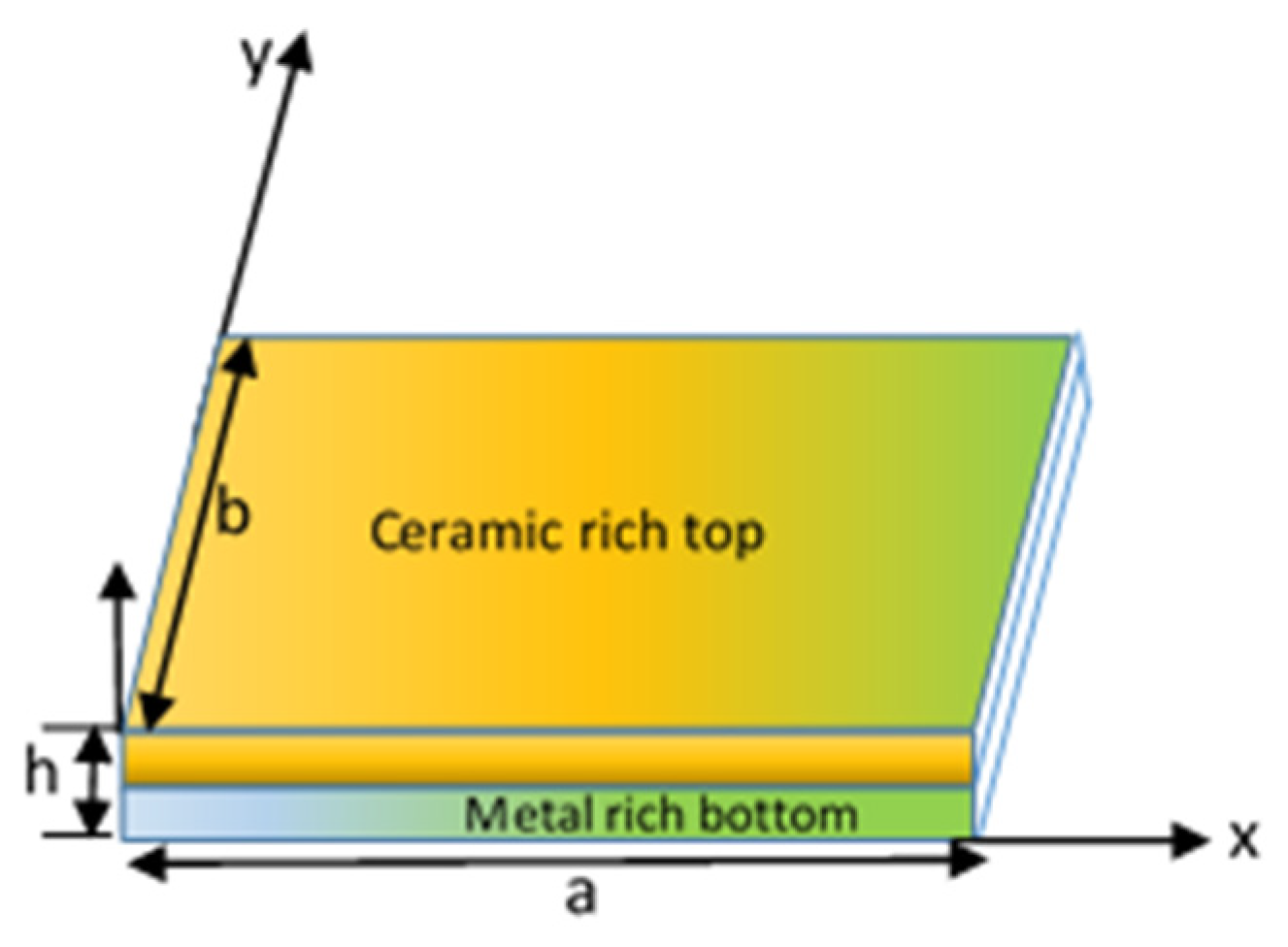
Figure 1. Geometry of plate with dimensions a × b.
Buildings 13 02577 g001
Figure 2. Nine-node element description.
Buildings 13 02577 g002
Figure 3. Discretization of FGM plate.
Buildings 13 02577 g003
Figure 4. Graphical representation of ceramic volume fraction distribution in Al/ZrO2 plate: (a) values of parameters a = 1, b = c = 0, (b) values of parameters a = 1, b = 1, c = 4, (c) values of parameters a = 1, b = 1, c = 2, (d) values of parameters a = 1, b = 0.5, c = 2, (e) values of parameters a = 1, b = 0.5, c = 2.
Buildings 13 02577 g004aBuildings 13 02577 g004b
Figure 5. Superimposition of shape functions.
Buildings 13 02577 g005
Figure 6. Variations in transverse displacement for various n values with different support conditions: (a) two edges clamped and two edged free, (b) all the four edges clamped, (c) two edges simply supported and two edges clamped, (d) all the edges simply supported.
Buildings 13 02577 g006
Figure 7. Variations in contour and displacement (transverse direction) for FGM plates.
Buildings 13 02577 g007
Figure 8. Variations in transverse displacement with various a/h values for different types of FGM plates: (a) classical profile, (b) symmetric profile, (c) asymmetric profile.
Buildings 13 02577 g008
Figure 9. Variations in transverse component with various a/b values for different types of FGM plates: (a) classical profile, (b) symmetric profile, (c) asymmetric profile.
Buildings 13 02577 g009
Figure 10. Variations in in-plane normal stress (σxx) distribution for FGM plates: (a) asymmetric profile, (b) a = 1, b = 0.5, c = 2, (c) a = 0.8, b = 0.2, c = 3, (d) classical profile, (e) symmetric profile.
Buildings 13 02577 g010
Figure 11. Variations in in-plane shear stress (τxy) distribution for FGM plates: (a) asymmetric profile, (b) a = 1, b = 0.5, c = 2, (c) classical profile, (d) symmetric profile, (e) a = 0.8, b = 0.2, c = 3.
Buildings 13 02577 g011
Figure 12. Variations in transverse shear stress (τyz) distribution for FGM plates: (a) classical profile, (b) symmetric profile, (c) asymmetric, (d) a = 1, b = 0.5, c = 2, (e) a = 0.8, b = 0.2, c = 3.
Buildings 13 02577 g012
Figure 13. Plate with a cutout subjected to tensile loading.
Buildings 13 02577 g013
Figure 14. Stress singularity pattern for various mesh configurations.
Buildings 13 02577 g014
Table 1. Volume fraction combinations of sandwich FGM plates.
TypeParameterProfileDistribution
FGM 1a = 1, b = c = 0ClassicalMetal and ceramic at the top and bottom, respectively
FGM 2a = 1, b = 1, c = 2SymmetricCeramic at the top and bottom
FGM 3a = 1, b = 1, c = 4AsymmetricCeramic at the top and bottom
FGM 4a = 1, b = 0.5, c = 2AsymmetricCeramic at the bottom/top and a combination of metal and ceramic at the top/bottom
FGM 5a = 0.8, b = 0.2, c = 3AsymmetricCeramic at the bottom/top and a combination of metal and ceramic at the top/bottom
Disclaimer/Publisher’s Note: The statements, opinions and data contained in all publications are solely those of the individual author(s) and contributor(s) and not of MDPI and/or the editor(s). MDPI and/or the editor(s) disclaim responsibility for any injury to people or property resulting from any ideas, methods, instructions or products referred to in the content.