Article

Theoretical Analysis of the Influence of Bearing Plate Position on the Bearing Performance of Soil around the CEP Antipull Force Double Pile

1
College of Civil Engineering, Jilin Jianzhu University, Changchun 130118, China
2
China Power Engineering Consulting Group, Northeast Electric Power Design Institute Co., Ltd., Changchun 130022, China
3
Tongyuan Design Group Co., Jinan 250101, China
*
Author to whom correspondence should be addressed.
Buildings 2023, 13(10), 2613; https://doi.org/10.3390/buildings13102613
Submission received: 6 September 2023 / Revised: 2 October 2023 / Accepted: 13 October 2023 / Published: 17 October 2023
(This article belongs to the Special Issue Building Foundation Analysis: Soil–Structure Interaction)

Abstract

:
With the development of large-scale projects such as high-rise buildings, deep-sea platforms, bridges, etc., these construction facilities are affected by many factors such as environment and geological conditions, which put forward higher requirements for pile-bearing capacity. Compared with the straight-hole grouted piles, the CEP (concrete expanded-plate) piles have an increased bearing plate, which has stronger resistance to pullout under the action of axial tension. The location of the bearing plate is the main factor affecting the bearing capacity of a CEP pile. This study simulates and analyzes CEP double piles on ANSYS software (Ansys R19.0 versions) under ideal conditions, designs five types of model piles with different bearing plate positions, and divides them into six groups for simulation. Finally, a complete model of the two-pile system is established. It is obtained that when the bearing plate is in the same position, the longer the pile length above the bearing plate, the greater the ultimate bearing capacity of the CEP double piles; when the bearing plates of a double pile are at different positions, the antipull-force-bearing capacity of the double pile mainly depends on the pile with a smaller pile length above the bearing plate, and determines the calculation mode of a CEP double-pile antipull-force-bearing capacity at different bearing plate positions, so as to provide a theoretical basis for the design and application of CEP pile foundations in large building structures in the future.

1. Introduction

As a new type of variable section cast-in-place pile gradually applied in engineering in recent years, the concrete expanded-plate (CEP) pile has the advantages of high bearing capacity, flexible design, small and even settlement, and simple construction technology; moreover, the new pile generator has the ability to improve the working environment on site [1], achieving the effect of high efficiency, energy conservation, and environmental protection [2,3,4], as shown in Figure 1. Compared with ordinary concrete straight hole cast piles, CEP piles have increased the bearing plate at the pile body position, and the bearing plate can be set flexibly at the pile body position as well as each parameter of the bearing plate, which changes the force mechanism of the pile body, greatly increases the contact area between the pile and the soil body, and increases the end-bearing force, which greatly improves the bearing capacity and stability of the pile body. At present, the foundation research on single piles of CEP pile has become mature [5,6,7,8], but the foundation research on pile groups is mostly based on ordinary concrete straight-hole cast-in-place piles [9,10], and research on CEP pile groups is still in the blank stage [11]; it seriously affects the development and application of CEP piles. When the pile spacing is insufficient, adjacent piles will have a greater mutual influence due to the special pile shaft structure of a CEP pile [12,13]. Thus, the bearing capacity of pile group foundations cannot be simply calculated as an integral multiple of single-pile foundations [14], and the position of the bearing plate is the main factor affecting the bearing capacity of CEP pile groups [15].
This study takes CEP double piles as the research object in an ideal condition, where the influence of the change of soil density during the penetration process of the pile [16,17] and the increase of the load during pile driving on the soil mass is neglected [18,19], sets the important parameter of the bearing plate position, and designs five types of model piles to be divided into six groups for finite element simulation of the same plate position and different plate positions. Compared with ABAQUS software (ABAQUS 2021 versions), ANSYS software (Ansys R19.0 versions) can achieve better simulation in static, quasi-static, and dynamic problems and linear analysis [20]; to this end, it is necessary to establish and address the following objectives and tasks through ANSYS software (Ansys R19.0 versions):
(1)
Establish the finite element model of CEP double-pile buckling resistance under different pile plate locations, and apply the face load of vertical tension on the top surface of the pile.
(2)
The top displacement of the pile, the failure state of soil around the pile, and the shear stress of each node of the pile shaft under the action of vertical tension are recorded. The six groups of results obtained are compared and analyzed, and the corresponding parameters are determined.
(3)
The calculation mode of the antipull-force-bearing capacity of CEP double piles with different bearing plates is modified, thereby providing a reliable theoretical basis for the calculation and design application of the bearing capacity of CEP pile groups.
(4)
Propose the main design principles of CEP double-pile buckling resistance in actual projects.

2. ANSYS Finite Element Model Construction

Basic assumptions for finite element simulation:
(1)
Since the deformation and force state of the soil body around the pile are mainly studied rather than the damage of the CEP pile itself, it is assumed that only the soil body is damaged throughout the simulation analysis, and the CEP double pile always maintains the elastic working state before reaching the ultimate bearing capacity. The pile body is set as a linear elastic material.
(2)
In order to make the goal of simulation analysis more clear and mainly study the influence of plate position, the soil body around the fixed pile adopts a single soil layer; a clayey soil layer is used, and the soil layer is set as elastic–plastic material.
(3)
The simulation analysis does not consider the influence of time effect, and the load is continuously applied step by step; the pile and soil are regarded as ideal materials with isotropic and uniform material.
(4)
Since the modeled length and width of soil body are much larger than the disc diameter of concrete spreading pile in the simulation, the influence of boundary conditions on the simulation results is not considered.

2.1. Model Size

With the bearing plate position as the only variable, the five model piles are divided into six groups for simulation, namely, MM1 group, MM2 group, MM3 group, MM4 group, MM5 group, and MM6 group. The bearing plates of two model piles in groups MM1–MM4 are the same, whereas the bearing plates of two model piles in groups MM5–MM6 are different. The detailed dimensions of the six groups of model piles are shown in Table 1 and Figure 2 and Figure 3.

2.2. Material Parameters

The soil parameters in the simulation are consistent with those in the actual geological exploration report to ensure that the simulation analysis is consistent with the actual situation [21,22]. The specific data of soil and pile parameters are shown in Table 2.

2.3. Establishment of Finite Element Model

In accordance with the material properties of the CEP pile shaft and soil around the pile, SOLID65 element is used for the CEP pile shaft during finite element simulation. SOLID65 element is a commonly used concrete element for ANSYS simulation, with tensile cracking and crushing properties. The soil around the pile adopts SOLID45 element, which is defined by eight nodes and has three degrees of freedom in X, Y, and Z directions.
The establishment process of the CEP double-pile finite element model is basically the same as that of the CEP single-pile finite element model [23,24], except that the soil model is changed from a cylinder to a cube compared to a single pile. The soil model is built from bottom to top, with the length, width, and height of 12,000, 10,000, and 8000 mm, respectively. The model pile is deducted from the soil by Boolean operation, as shown in Figure 4, and then the model pile is combined with the soil. It conforms to the construction process of drilling–expanding plate body–lowering reinforcement cage–pouring concrete in the actual project.
The model after mapped grid division is shown in Figure 5.

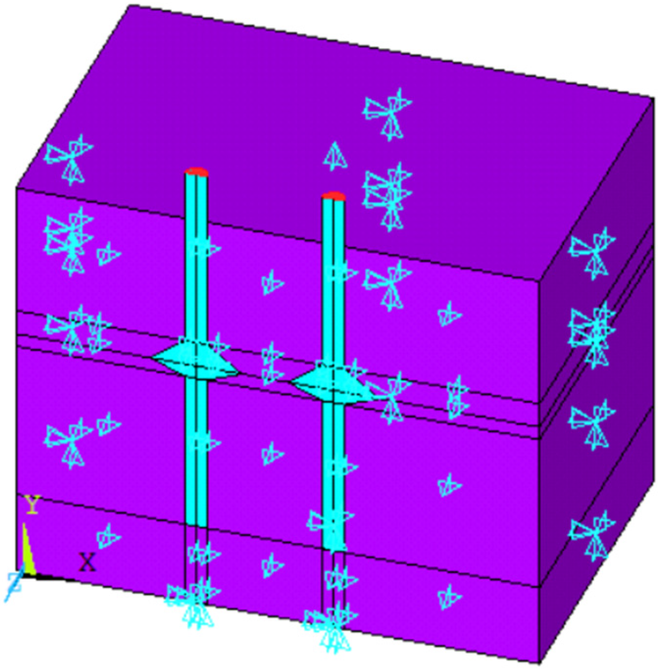
2.4. Constraints and Load Methods

2.4.1. Setting of Constraints

In the loading process, the degrees of freedom of each surface of the hexahedron soil must be constrained to prevent large errors caused by soil movement [25]. The front of the hexahedron only constrains the degrees of freedom in the Y direction, and the top face constrains the degrees of freedom in both the X and Y directions. The remaining four faces are constrained in all three directions.

2.4.2. Load Application

In this simulation, we apply the axial tensile load, and adopt the progressive loading mode of long-term loading, with each level of 100 kN. It is applied to the top surface of the pile in the form of surface load. In accordance with the load displacement data extracted from the simulation analysis, when the pile top displacement reaches a sudden change or 100 mm, the load is considered a limit load, terminates the continued loading, and determines the result, as shown in Figure 6.

3. Displacement Nephogram Analysis of ANSYS Simulation Results

The displacement nephogram of the model pile under various loads is obtained, the analysis data are extracted, and the load displacement curves of the six groups of CEP double piles are drawn through ANSYS finite element analysis. The rules whereby the locations of the same plate and different plates affect the antipull-force-bearing capacity and failure state of CEP double piles are summarized and analyzed.

3.1. Displacement Nephogram Analysis during Loading

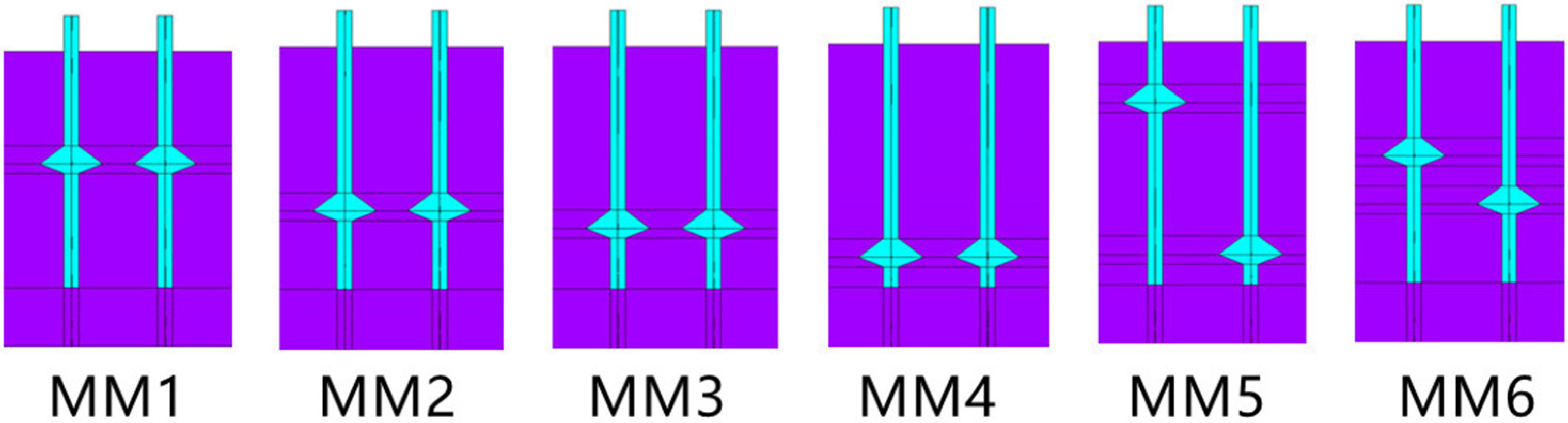
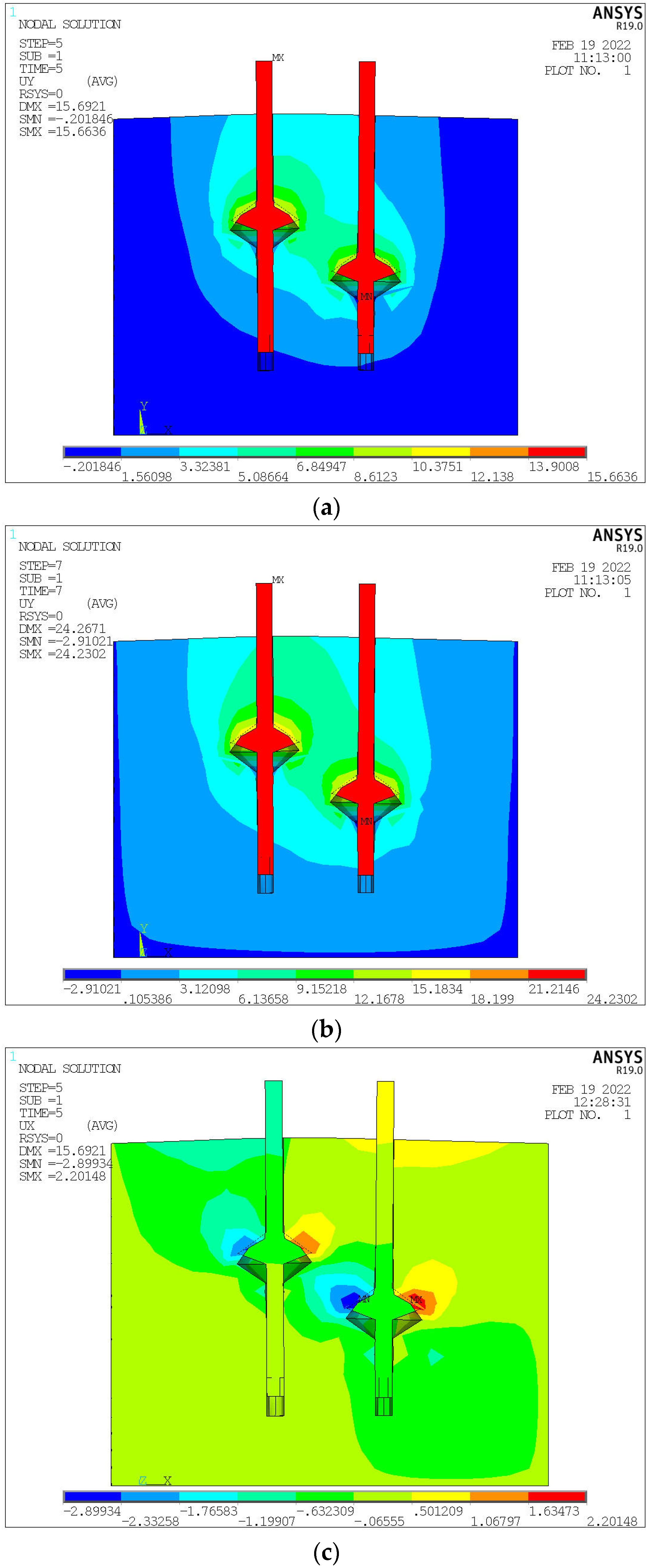
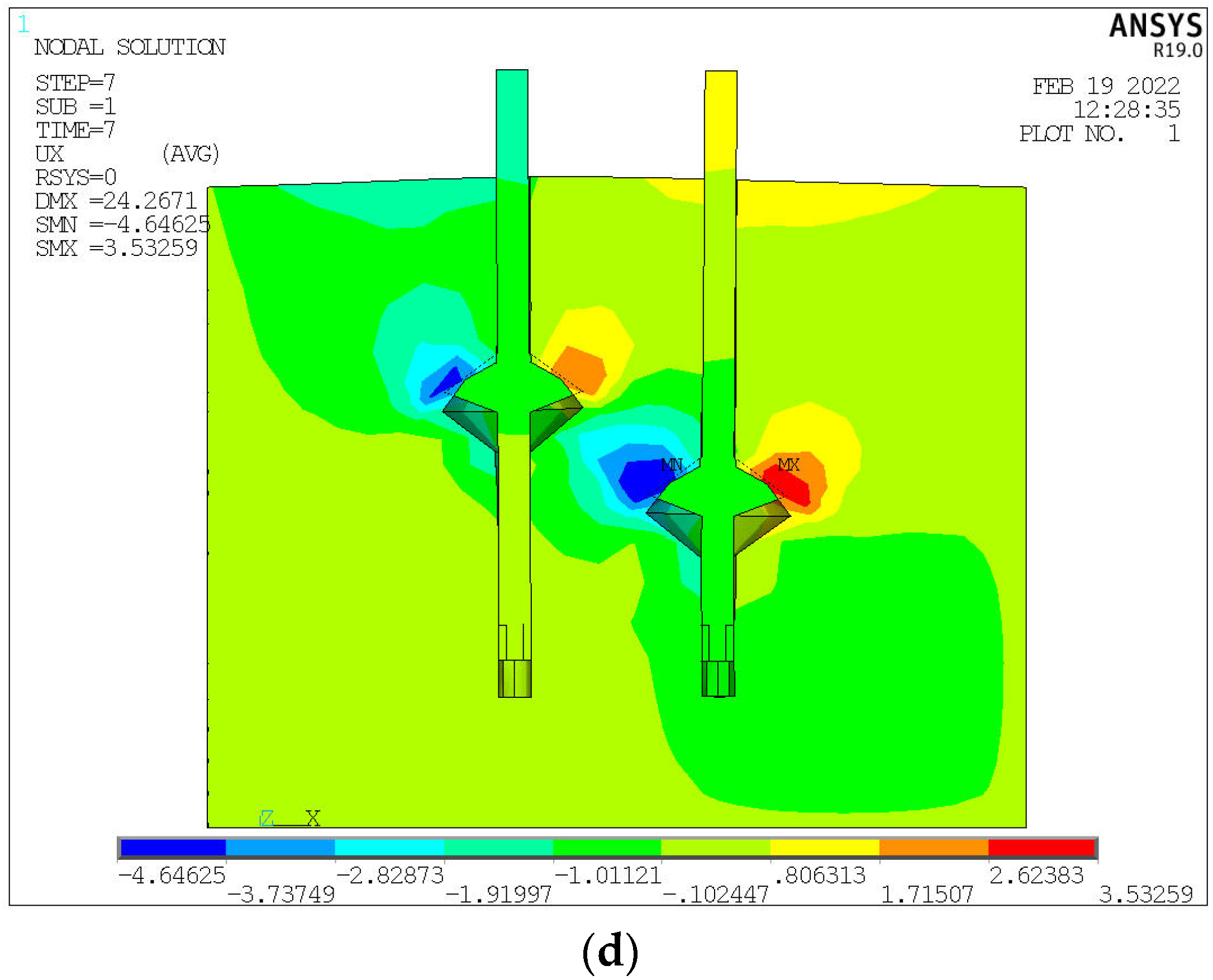
3.1.1. The CEP Double-Pile-Bearing Plates at the Same Position

For a more detailed and intuitive observation, the displacement nephogram of CEP double piles and soil around the piles in the simulation analysis is extracted under different loading levels. The MM1 group of pile types at the same position of the bearing plate is selected for detailed description, and the vertical displacement nephogram when the vertical tension is 100, 300, 500, 700, 1100, and 1200 kN is extracted for analysis, as shown in Figure 7.
When the first stage load of 100 kN is completed, the soil mass above the bearing plate is compressed and deformed by about 1.5 mm. The influence range and deformation of the soil mass around the pile are small, as shown in Figure 7a. When the load is increased to 300 kN, the deformation and influence range of the soil at the upper right of the left pile-bearing plate and the soil at the upper left of the right pile-bearing plate are slightly larger than those at the opposite side due to the interaction between the two piles, but they are still in the linear working stage, as shown in Figure 7b. At 500 kN, the soil at the lower left part of the left pile-bearing plate and the soil at the lower right part of the right pile-bearing plate are pulled apart, resulting in relative displacement, but they have minimal impact on the bearing performance, as shown in Figure 7c. As shown in Figure 7d, the displacement of the pile top is about 25 mm, the relative displacement of the soil mass is connected, the cohesion between the soil particles on and under the bearing plate disappears, shear failure occurs, and the soil mass under the bearing plate stops the work when the load is increased to 700 kN. The soil-bearing capacity mostly disappears after 700 kN due to the increased relative displacement of the soil between the bearing plates of the two piles, as shown in Figure 7e. With the increase in load, the two piles as a whole gradually produce punching failure to the soil on two sides, and the displacement increment increases remarkably. When the load reaches 1200 kN, the ANSYS simulation analysis stops working, reaches failure, and the loading is terminated, as shown in Figure 7f.

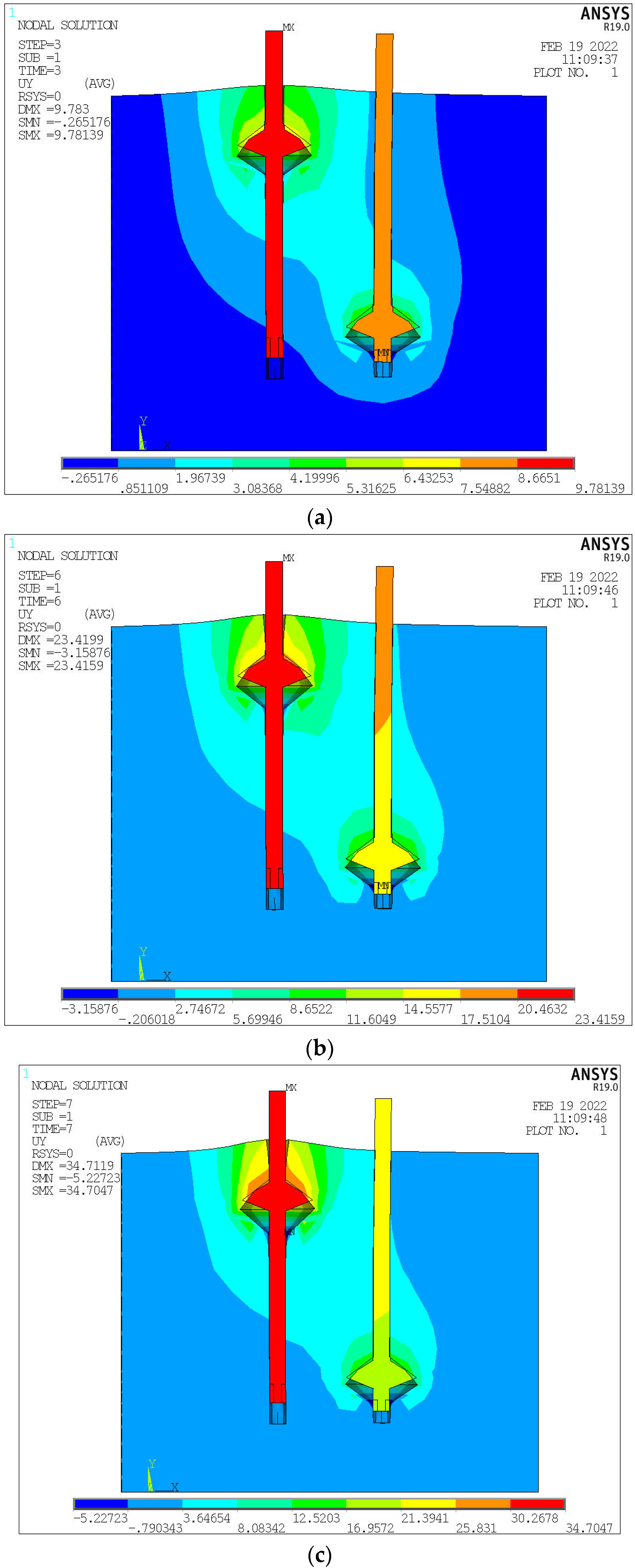
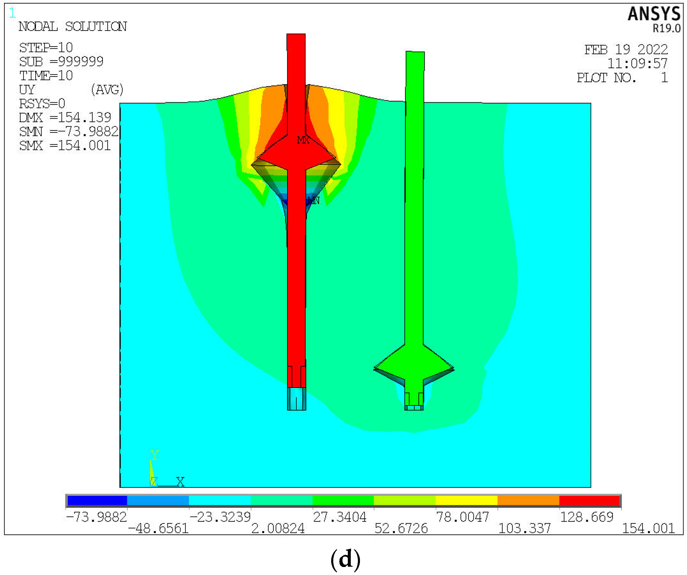
3.1.2. The CEP Double-Pile-Bearing Plate at Different Positions
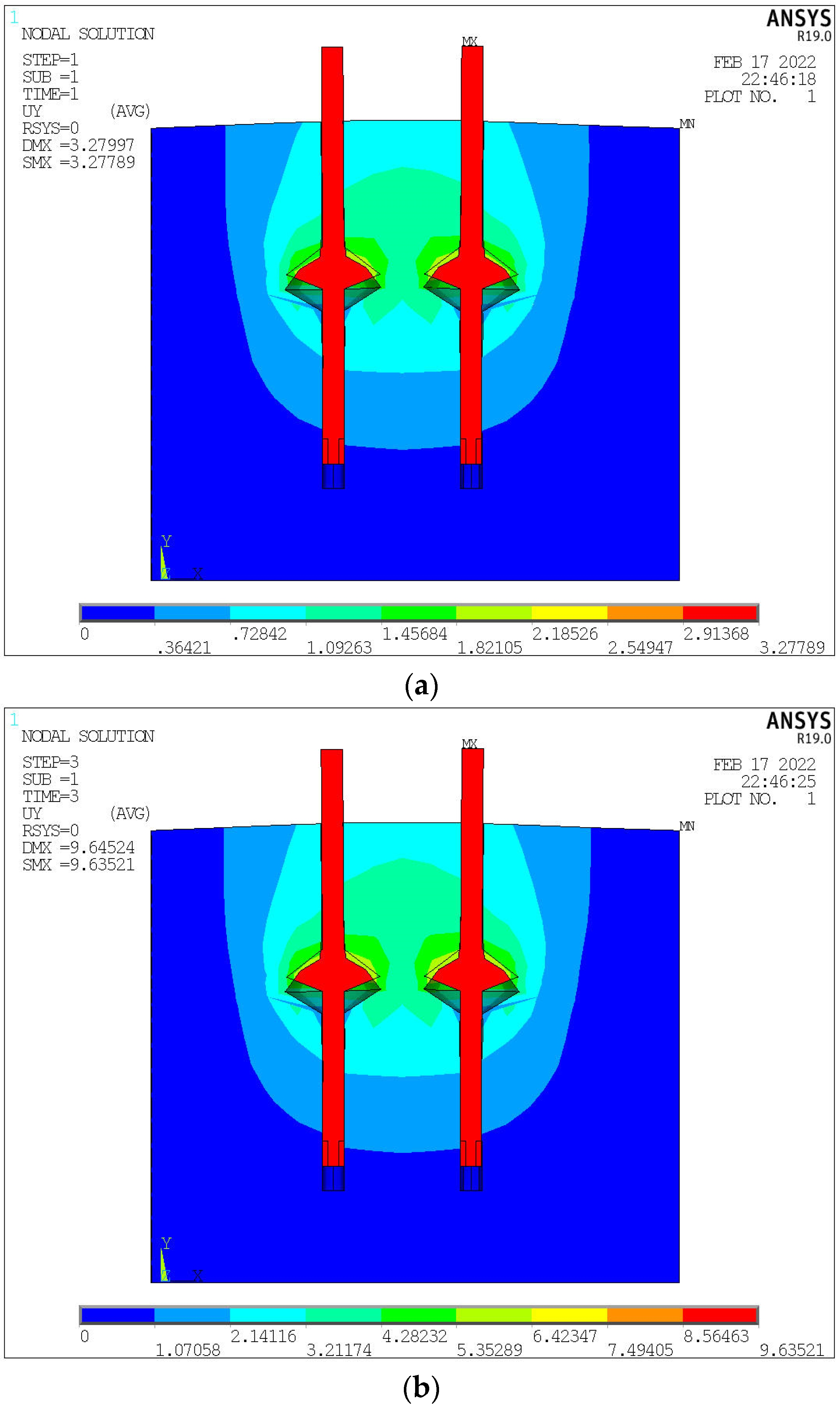
(1)
Displacement nephogram analysis of the MM5 group loading process
The vertical distance between the bearing plates of two piles in the MM5 group is 6.25R0. The corresponding vertical displacement nephogram when the load is 300, 600, 700, and 900 kN is taken for analysis, as shown in Figure 8.
When the load is 100–300 kN, the displacement of pile top increases linearly with the increase in load, as shown in Figure 8a. When the displacement reaches 25 mm, the load is about 615 kN, as shown in Figure 8b,c, which is less than the load of the first four groups, indicating that the bearing capacity is greatly reduced mainly because the pile length d1 above the left pile-bearing plate is small. A large vertical displacement difference is observed because of the large difference between the positions of the bearing plates of the two piles. The settlement difference between the two piles is 3.95 mm at 615 kN, and the vertical displacement difference between the two piles reaches 25.33 mm at final failure, as shown in Figure 8d. This finding shows that the vertical displacement difference between two piles increases with the increase in load. In the actual project, large additional stress will be caused in the foundation, which should be avoided in the design.
(2)
Displacement nephogram analysis of the MM6 group during loading process
The vertical distance between the bearing plates of two piles in the MM6 group is 2R0. Different from the first five groups of piles, the two piles have horizontal displacement during the loading process of MM6 group because the soil mass between the two pile plates affects each other, so the vertical displacement and lateral displacement nephograms at 500 and 700 kN are extracted for analysis, as shown in Figure 9.
When the load increases from 0 kN to 500 kN, the displacement of the pile top increases linearly, and the soil around the pile deforms in a “band” shape along the connecting line of the two plates, as shown in Figure 9a. The displacement reaches about 24 mm at 700 kN, as shown in Figure 9b. As shown in Figure 9c,d, the top of the two piles moves away from the direction of the other pile, reaching about 3.5 mm at 700 kN. This condition is because the soil on the upper right side of the left side is subjected to the normal stress inclined to the right, which is transferred to the vicinity of the right pile top, affecting the right pile, and causing the right pile top to move to the right. The left pile top is subjected to the normal stress inclined to the left on the upper left side of the right side, causing the left pile top to move to the left. Therefore, the two pile-bearing plates will produce additional moments of the pile shaft due to mutual influence when the distance between the two plates in the Y direction is 2R0, which will adversely affect the bearing capacity.

3.2. Load Displacement Curve Analysis

The load displacement values of the six groups of simulated piles are extracted to draw the load displacement curves of the six groups of model piles, as shown in Figure 10.
The observations made from analyzing the load displacement curve in Figure 10 are as follows:
(1)
At the initial simulation loading stage of the MM1–MM6 groups of double-pile models, the change trend of load displacement curve is the same, as shown in the red section of Figure 10. At this time, the displacement of the pile top increases linearly with the increase in load, mainly relying on the side friction of double piles and the local soil above the bearing plate to provide the bearing capacity. The bearing plate does not play a role in the bearing capacity of CEP double piles.
(2)
In the middle and late stages of loading (outside the red line), the farther the bearing plate is from the soil surface, the smaller the pile top displacement, the greater the load corresponding to failure, and the greater the bearing capacity of the pile with the pile length d1 above the bearing plate under the same load. However, the greater the distance between the bearing plate and the soil surface, the slower the growth rate of its bearing capacity. Under the same load, the pile top displacement of the MM6 group is remarkably smaller than that of the MM5 group. Thus, the antipull-force-bearing capacity of the MM6 group is remarkably greater than that of the MM5 group, and the bearing capacity of the bearing plate of the MM5 group is not fully utilized, and the soil has been damaged, so the antipull-force-bearing capacity mainly depends on the pile with a small pile length d1 above the bearing plate.
(3)
Under the same load, the antipull-force-bearing capacity of groups M2–M4 is larger, and that of group M4 is the largest. Therefore, the antipull-force-bearing capacity of double piles with the bearing plate at the same position is greater when the pile length d1 above the bearing plate is greater than 4R0.
For the steep drop load–displacement curve (MM1, MM5, MM6), the ultimate bearing capacity takes the load value corresponding to the starting point where the obvious steep drop occurs; for the slow variable load–displacement curve (MM2, MM3, MM4), the ultimate bearing capacity can be determined according to the pile top displacement, taking the corresponding load value when the pile top displacement is 100 mm.
The ultimate bearing capacity Fu diagram of each group is shown in Figure 11. A large difference is observed between MM1, MM5, MM6, and the other three groups of Fu, where the MM5 group is only 600 kN, and the MM1 and MM6 groups are about 1000 kN. This condition is because the pile length d1 on the bearing plate is extremely short, which is caused by punching failure.

4. Shear Stress Curve Analysis of ANSYS Simulation Results

For the six groups of model piles, the shear stress values of each node of the pile shaft in the loading process of groups MM1–MM4 with bearing plates at the same position and groups MM5 and MM6 with bearing plates at different positions are analyzed.

4.1. The CEP Double-Pile-Bearing Plates at the Same Position
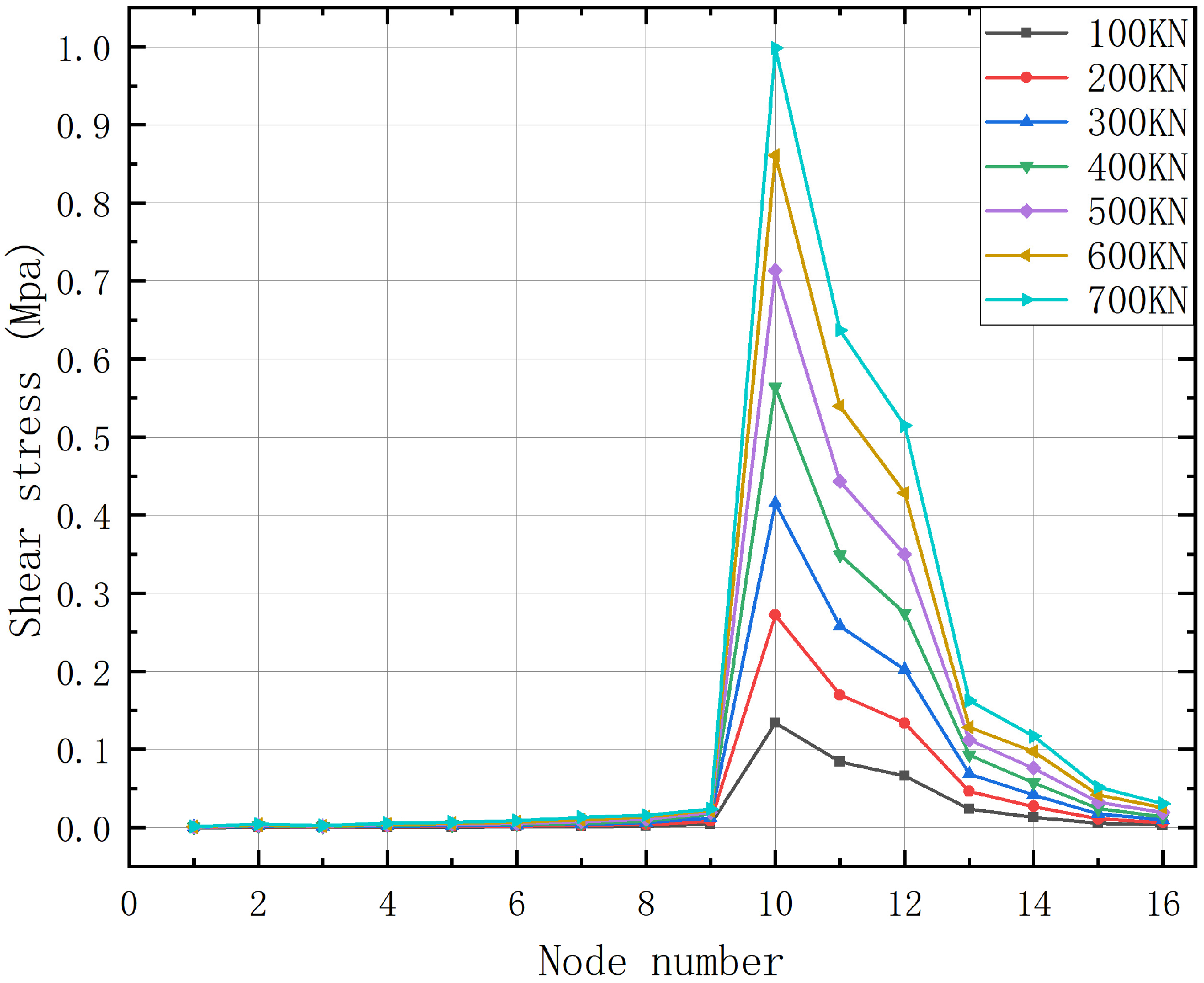
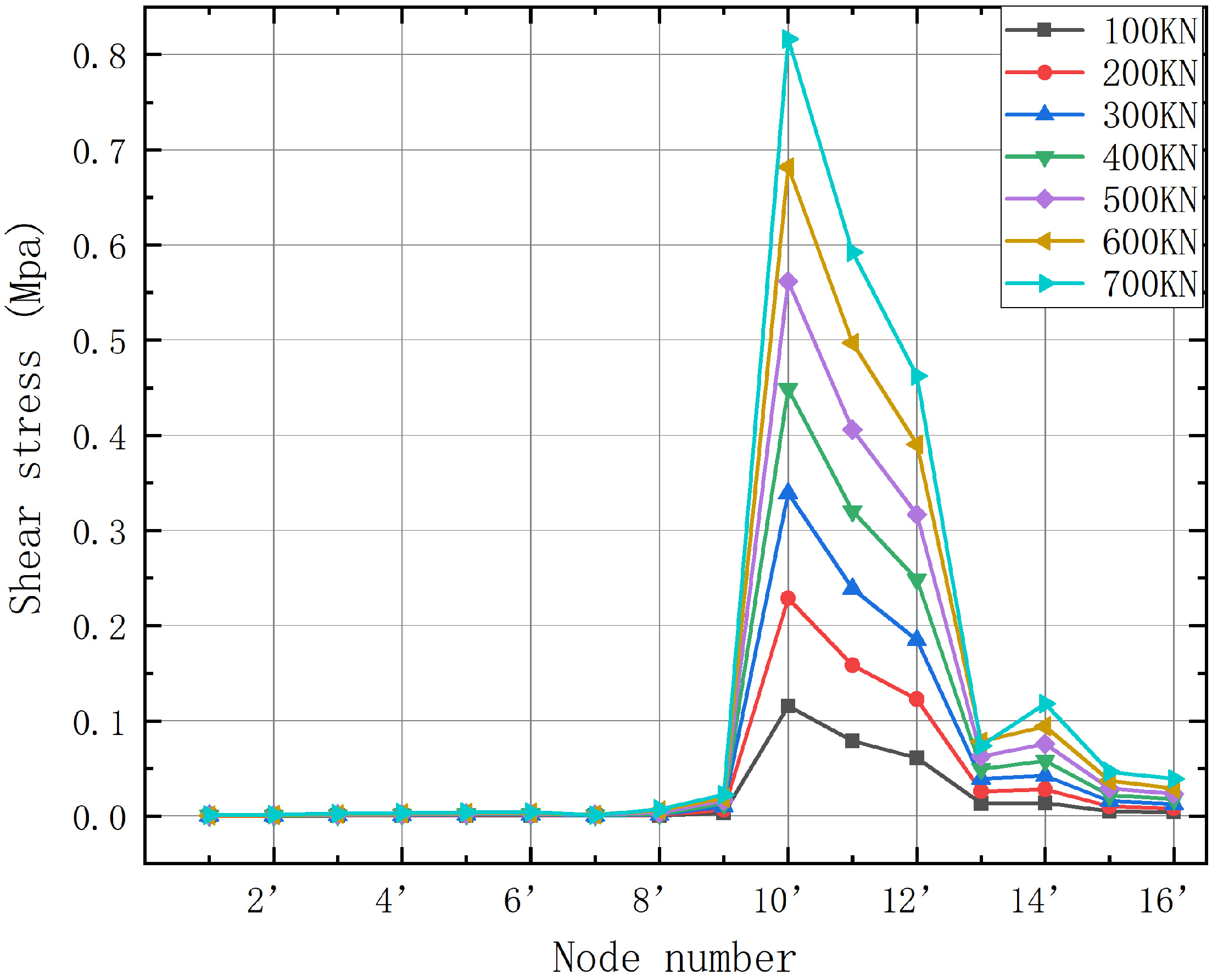
The right side of the left pile and the left side of the right pile are called the “influence side”, as shown by the yellow bold line in Figure 12. The other two sides are called the “normal side”, as shown by the pink bold line in Figure 12.
The MM3 group is selected to study the loading process at the same position of the bearing plate. Sixteen points are evenly selected along the pile shaft on two sides of the left pile, and the loading process of 0–700 kN (at this time, the displacement of the pile top increases linearly with the increase in load) is extracted. The shear stress values of 32 points on the normal side and the influence side of the left pile are shown in Figure 13, and the shear stress change diagrams of each part of the pile shaft on two sides with the loading of MM3 pile are shown in Figure 14 and Figure 15.
The observations made by analyzing Figure 14 and Figure 15 are as follows:
(1)
Compared with the six corresponding shear stress curves when loading on the same side, the position of the bearing plate from the beginning of loading bears approximately more than 80% of the antipull of the pile shaft, and the compressive pile is lower than this value, about 60%. This condition is because the soil mass at the bottom of the compression pile can provide most of the end-bearing capacity and bear down pressure together with the bearing plate. The antipull force pile only has the bearing plate to provide the end-bearing capacity, which causes excessive concentration of the shear stress of the bearing plate and the pile diameter near the bearing plate. Therefore, the antipull force CEP pile should be further densified with steel bars near the bearing plate compared with the compression pile during the design to ensure the safety of the project.
(2)
The maximum shear stress occurs at numbers 10 and 10’, that is, the junction of the bearing plate and the upper pile diameter. Extremely large sudden changes in shear stress are observed between points 9 and 10, and between points 9’ and 10’, approximately from zero to the maximum, which is prone to brittle failure. The main reason for this phenomenon is because the pile top transmits the vertical antipull force to the bearing plate through the upper pile diameter, and the bearing plate bears approximately 80% of the load, so an extremely large shear stress mutation occurs at the junction of the bearing plate and the upper pile diameter. Therefore, this position can be designed as a circular arc during antipull force resistance in actual projects. Although the engagement between the bearing plate and the soil around the plate is weakened, this condition will greatly reduce the shear stress mutation at the junction of the bearing plate and the upper pile diameter, and decrease the risk of damage.
(3)
The shear stress of the lower pile diameter is greater than that of the upper pile diameter, and the shear stress of the upper pile diameter is approximately zero when CEP piles are antipull-force-resistant by comparing numbers 1–9, 1’–9’ nodes and numbers 13–16, 13’–16’ nodes. This finding shows that the role of the upper pile diameter is mainly to transfer the antipull force load of the pile top to the bearing plate and then transfer the stress to the soil around the pile by the bearing plate and the lower pile diameter to provide the bearing capacity.
The maximum point of shear stress of the bearing plate is point 10, then point 11, point 12, and point 13 in order. From Figure 16, except for point 13, the ratio of shear stress between two sides of the pile at the remaining three points is between 0.75 and 0.95, and the ratio is relatively concentrated. It shows that the mutual influence between two piles at these three points is not much different, and the shear stress on the influence side is discounted to about 0.9 compared with that on the normal side (taking the average value). The shear stress at point 13 is very small, only 15% of that at point 12, so its ratio of shear stress is negligible. The ratio of shear stresses on both sides is slowly decreasing with the increase of load. It shows that when the load is small, the reduction of shear stress on the influence side is small compared with the normal side, i.e., the degree of mutual influence between the two piles is weak. With the increase of load, the shear stress reduction also becomes larger, and the ratio decreases from 0.9 at 0 kN–700 kN to 0.86 at 1000 kN.

4.2. The CEP Double-Pile-Bearing Plate at Different Positions

The vertical distance between the bearing plates of two piles in group MM5 is 6.25R0. The two plates have minimal effect in the load range of 0–700 kN because their vertical distance is extremely large, so group MM6 is taken to study the shear stress on two sides of the double piles at different positions.
The shear stresses corresponding to the 700 kN load on the normal side of the left pile, the influence side of the left pile, the influence side of the right pile, and the normal side of the right pile are extracted. Sixteen points along the pile shaft at each side are taken, with a total of 64 points, and the shear stress change curve of the pile shaft under 700 kN load is shown in Figure 17.
As shown in Figure 17, the shear stress at the bearing plate with different positions decreases remarkably, unlike the shear stress change when the bearing plate is at the same position. This condition is due to the dislocation of the bearing plates of two piles, and the disturbed soil cannot provide sufficient shear stress for the bearing plate.
The left pile affects the shear stress of the side bearing plate more seriously than the right pile, which is 74.31% for the left pile and 92.43% for the right pile, with a difference of about 18%. Specifically, the impact on the shear stress of the plate with relatively small burial depth is greater when the two pile-bearing plates are at different positions. However, the total shear stress of the two piles is equal, which indicates that the normal side of the pile with a smaller pile length d1 on the plate will bear a greater shear stress, which is also the reason why the maximum shear stress of the normal side of the left pile is greater than that of the right pile. Therefore, special attention should be paid to the pile with smaller pile length d1 above the bearing plate when it is in different positions in the actual project.

5. Calculation Mode for Antipull-Force-Bearing Capacity of CEP Double Piles

On the basis of the original calculation model of the antipull-force-bearing capacity of CEP single piles, the reduction factor of the antipull-force-bearing capacity of CEP double piles at different plate locations when the distance between two piles is 4R0 is α. The antipull-force-bearing capacity calculation mode of CEP double piles is proposed.

5.1. Calculation Mode of CEP Single-Pile-Bearing Capacity

When the soil on the bearing plate is not subject to punching failure under vertical tension, the soil around the pile is subject to sliding failure [26]. On the basis of the virtual work principle and slip line theory, a formula for calculating the bearing capacity of CEP antipull force for a single pile is proposed (1)~(4). The strain field in the Prandtl region of the soil on the bearing disk and the range of variation of the pile lateral friction resistance are shown schematically in Figure 18 and Figure 19.
F p u l l   o u t = F d i s k   e n d + F p i l e   s i d e + G p i l e
F d i s k   e n d = 1 2 π c cot ϕ R 0 e 2 θ tan ϕ 1
F p i l e   s i d e = f s i d e π d L 0 = f s i d e π d L H L b + γ L a
G p i l e = π γ G 12 3 d 2 L H + H D 2 + D d + d 2
1D, d, and R 0 = plate diameter, pile diameter, and cantilever diameter {plate cantilever diameter = ½(plate diameter–pile diameter)};
c —cohesive force of soil;
ϕ —internal friction angle of soil;
L —pile length;
H —pile plate height;
γ —increase factor, 1.1–1.2;
L a —increased range of horizontal compressive stress around the main pile on the plate;
L b —the horizontal tensile stress range appears around the main pile under the plate.
Figure 18. Strain field in the Prandtl region of the soil on the bearing plate.
Buildings 13 02613 g018
Figure 19. Schematic diagram of the range of variation of pile lateral resistances.
Buildings 13 02613 g019

5.2. The Reduction Factor α and the Determination of the Calculation Formula

Antipull force simulation finite element analysis of MEP double piles of the MM1–MM4 groups corresponding to MEP single piles of the M1–M4 groups are conducted, and the pile top load displacement data are extracted. Linear interpolation is used to extract the limit load values of M1–M4 and MM1–MM4 groups, and the ratio of the MM1–MM4 groups of double piles to the M1–M4 groups of single piles is calculated. The results are shown in Table 3. Therefore, the CEP double-pile tensile-bearing capacity is calculated as shown in Equation (5).
F d p u l l   o u t = α F d i s k   e n d + F p i l e   s i d e + 2 G p i l e ,

6. Conclusions

(1)
In this paper, the simulation study on the pull-out bearing capacity of CEP double piles mainly analyzes the influence of the bearing plate position on the bearing performance of CEP double piles, compared with the bearing performance of single piles. It can be learned that within a certain pile spacing, the bearing capacity of CEP double piles is not twice the bearing capacity of single piles, the interaction between the two bearing plates of CEP double piles results in the folding down of the bearing capacity, which is due to the fact that when CEP double piles are subjected to the vertical tensile force, the load is transferred to the bearing plate through the pile body; the bearing plate and the soil around the pile are in contact with each other, the bearing plate plays the main bearing role, the soil is extruded above the bearing plate, and the soil above the bearing plate generates slip; with the change of different bearing plate positions, the bearing capacity of the double pile is also changing.
(2)
When the pile spacing and bearing plate position of CEP double piles are set reasonably, the failure state of soil around each pile is the same as that of the single pile. When the bearing plates of double piles are at the same position, the greater the pile length d1 above the bearing plates, the greater the ultimate bearing capacity of CEP double piles. When the bearing plates of double piles are at different positions, the antipull-force-bearing capacity of double piles mainly depends on the pile with a smaller pile length d1 above the bearing plate. The pile length d1 above the bearing plate should be greater than 4R0 as much as possible to avoid punching failure.
(3)
The main design principles of CEP double-pile antipull force resistance in actual projects are proposed as follows:
  • The position of the bearing plates of two piles should be the same as much as possible, and the pile length d1 above should be greater than 4R0.
  • When the positions of the bearing plates of two piles are different, the pile length d1 above the bearing plates should be greater than 4R0, and the vertical distance between the bearing plates of two piles should meet the requirement of no mutual influence and does not need to be larger.
  • At the time of design, tensile CEP piles should be rebar-encrypted near the load-bearing plate compared to antipressure CEP piles.
  • During antipull force, the interface between the bearing plate and the main pile diameter can be designed as a circular arc.
(4)
The calculation formula of CEP double-pile pullout bearing capacity was established, which can effectively arrange the number of piles used in the actual project and reduce the waste of concrete.

7. Outlook

In this paper, the influence of tensile capacity of CEP double piles under different pile plate positions is deeply studied by ANSYS finite element simulation software, which fills in the gap of the research on tensile capacity of CEP double piles, and provides a reliable theoretical basis for the calculation of the capacity of CEP group piles and the design and application of CEP group piles, which reasonably arranges the number of piles and reduces the waste of concrete compared with the straight-hole grouted piles. However, there are many other factors affecting the tensile-bearing capacity of CEP double piles in actual projects, such as soil layer properties, number of bearing plates, bearing plate angle, etc. In the next step, it is necessary to consider the influence of many factors on the bearing capacity of CEP double piles, and to improve the theory of the research on CEP piles.

Author Contributions

Conceptualization, Y.Q. and L.S.; methodology, Y.Q.; software, L.S.; validation, L.A., Y.Z. and M.L.; formal analysis, Y.Q.; investigation, Y.Q.; resources, Y.Q.; data curation, Y.Q.; writing—original draft preparation, L.S.; writing—review and editing, L.S.; visualization, Y.Q.; supervision, Y.Q.; project administration, Y.Q.; funding acquisition, Y.Q. All authors have read and agreed to the published version of the manuscript.

Funding

This research was funded by the National Natural Science Foundation of China under Grant number 52078239.

Data Availability Statement

Not applicable.

Conflicts of Interest

The authors declare no conflict of interest.

References

  1. Baohan, S. Special Lecture on New Technology of Pile Foundation Construction(thirty-one) Construction method of drilling-expanding-clearing integrated machine and its multi-section drilling and expanding pile. Eng. Mach. Maint. 2014, 106–108+110–114. [Google Scholar]
  2. Qian, Y.; Li, M.; Wang, R.; Jin, Y. Theoretical study on the load carrying capacity of concrete drilled and expanded piles with different stiffness under horizontal load. IOP Conf. Ser. Earth Environ. Sci. 2021, 760, 012002. [Google Scholar] [CrossRef]
  3. Zhang, M.; Xu, P.; Cui, W.; Gao, Y. Bearing behavior and failure mechanism of squeezed branch piles. J. Rock Mech. Geotech. Eng. 2018, 10, 935–946. [Google Scholar] [CrossRef]
  4. Ting, L.; Peng, X.; Yang, G. Investigation into bearing performance of concrete expanded-plates piles: Field test and numerical modelling. Eng. Struct. 2022, 271, 114954. [Google Scholar]
  5. Ma, H.; Wu, Y.; Tong, Y.; Jiang, X. Research on bearing theory of squeezed branch pile. Adv. Civ. Eng. 2020, 2020, 6637261. [Google Scholar] [CrossRef]
  6. Qian, Y.; Wang, J.; Wang, R. The analysis of the vertical uplift bearing capacity of single CEP pile. Open Civ. Eng. J. 2015, 9, 598–601. [Google Scholar] [CrossRef]
  7. Chen, Y.; Qian, Y.; Hong, G.; Jin, Y.; Wang, R. Study of undisturbed soil test about slope angle of the expanded-plate affecting the failure mechanism of the NT-CEP pile under vertical tension. J. Phys. Conf. Ser. 2022, 2202, 012023. [Google Scholar] [CrossRef]
  8. Tian, W.; Qian, Y.; Lang, S.; Wang, R. The Undisturbed-Soil Experimental Analysis of the Destructive-State Influence of the Plate Diameter under the Vertical Tension on the CEP Pile. Chem. Eng. Trans. 2018, 66, 445–450. [Google Scholar]
  9. Hadi, D.H.; Waheed, M.Q.; Fattah, M.Y. Effect of Pile’s Number on the Behavior of Piled Raft Foundation. Eng. Technol. J. 2021, 39, 1080–1091. [Google Scholar] [CrossRef]
  10. Fattah, M.Y.; Al-Obaydi, M.A.; Al-Jalabi, F.A. Effect of number of piles on load sharing in piled raft foundation system in saturated gypseous soil. Int. J. Civ. Eng. Technol. 2018, 9, 932–944. [Google Scholar]
  11. Al-Suhaily, A.S.; Abood, A.S.; Fattah, M.Y. Bearing capacity of uplift piles with end gates. In Proceedings of the China-Europe Conference on Geotechnical Engineering, Vienna, Austria, 13–16 August 2016; Springer International Publishing: Cham, Switzerland, 2018; Volume 2, pp. 893–897. [Google Scholar]
  12. Liang, F.; Yu, F.; Han, J. A simplified analytical method for response of an axially loaded pile group subjected to lateral soil movement. KSCE J. Civ. Eng. 2013, 17, 368–376. [Google Scholar] [CrossRef]
  13. Zhang, H.; Li, C.; Yao, W.; Long, J. A novel approach for determining pile spacing considering interactions among multilayered sliding masses in colluvial landslides. KSCE J. Civ. Eng. 2019, 23, 3935–3950. [Google Scholar] [CrossRef]
  14. Fan, Y.; Wang, J.; Feng, S. Effect of spudcan penetration on laterally loaded pile groups. Ocean. Eng. 2021, 221, 108505. [Google Scholar] [CrossRef]
  15. Qian, Y.; Chao, S.; Wang, R. Theoretical Analysis of Plate Location Effect on Soil Failure State under Horizontal Force of a Concrete Plate-Expanded Pile Used for Oceanographic Engineering. J. Coast. Res. 2020, 106, 655–659. [Google Scholar] [CrossRef]
  16. Dobrzycki, P.; Kongar-Syuryun, C.; Khairutdinov, A. Vibration reduction techniques for Rapid Impulse Compaction (RIC). J. Phys. Conf. Ser. 2019, 1425, 012202. [Google Scholar] [CrossRef]
  17. Herbut, A.; Khairutdinov, M.; Kongar-Syuryun, C.; Rybak, J. The surface wave attenuation as the effect of vibratory compaction of building embankments. IOP Conf. Ser. Earth Environ. Sci. 2019, 362, 012131. [Google Scholar] [CrossRef]
  18. Khayrutdinov, M.; Kongar-Syuryun, B.; Khayrutdinov, M.; Tyulyaeva, Y.S. Improving Safety when Extracting Water-soluble Ores by Optimizing the Parameters of the Backfill Mass. Occup. Saf. Ind. 2021, 1, 53–59. [Google Scholar] [CrossRef]
  19. Golik, I.; Kongar-Syuryun, B.; Michałek, A.; Pires, P. Ground transmitted vibrations in course of innovative vinyl sheet piles driving. J. Phys. Conf. Ser. 2021, 1921, 012083. [Google Scholar] [CrossRef]
  20. Baca, M. Numerical Modeling of Pile Installation Influence on Surrounding Soil. In Proceedings of the 17th International Multidisciplinary Scientific GeoConference, SGEM 2017, Albena, Bulgaria, 27 June–6 July 2017. [Google Scholar]
  21. Han, W.F.; Feng, B.B.; Zhou, J.; Lu, C.Y. The Study on the Engineering Properties of Squeezed Branch Piles under Combined Load. Appl. Mech. Mater. 2014, 580–583, 371–375. [Google Scholar] [CrossRef]
  22. Yin, L.; Fan, X.; Wang, S. A study on application of squeezed branch pile in clay soil foundation. IOP Conf. Ser. Earth Environ. Sci. 2017, 61, 012091. [Google Scholar] [CrossRef]
  23. Qian, Y.; Yang, Y.; Hong, G.; Tian, W.; Song, Y. Theoretical Analysis of the Influence of a Sectional Form of a Flexible NT-CEP Pile Disc on the Anti-tilting Loading Performance. KSCE J. Civ. Eng. 2022, 26, 4709–4716. [Google Scholar] [CrossRef]
  24. Baca, M.; Rybak, J. Pile Base and Shaft Capacity under Various Types of Loading. Appl. Sci. 2021, 11, 3396. [Google Scholar] [CrossRef]
  25. Kahyaoglu, M.R.; Imançli, G.; Önal, O.; Kayalar, A.S. Numerical analyses of piles subjected to lateral soil movement. KSCE J. Civ. Eng. 2012, 16, 562–570. [Google Scholar] [CrossRef]
  26. Qian, Y. Study on Damage Mechanism of Soil around Concrete Spread Plate Pile and Vertical Bearing Capacity of Single Pile; China Building Industry Press: Beijing, China, 2018; Volume 11. [Google Scholar]
Figure 1. Schematic diagram of the CEP pile.
Buildings 13 02613 g001
Figure 2. Design details of the simulated pile.
Buildings 13 02613 g002
Figure 3. Schematic of the model pile for simulation analysis.
Buildings 13 02613 g003
Figure 4. Establishing the pile–soil model.
Buildings 13 02613 g004
Figure 5. Meshing.
Figure 5. Meshing.
Buildings 13 02613 g005
Figure 6. Schematic of restraint and load action position.
Buildings 13 02613 g006
Figure 7. Displacement cloud diagram of the MM1 group during loading process: (a) 100 kN Y direction; (b) 300 kN Y direction; (c) 500 kN Y direction; (d) 700 kN Y direction; (e) 1100 kN Y direction; (f) 1200 kN Y direction.
Buildings 13 02613 g007aBuildings 13 02613 g007bBuildings 13 02613 g007c
Figure 8. Displacement cloud diagram of the MM5 group during loading process: (a) 300 kN Y direction; (b) 600 kN Y direction; (c) 700 kN Y direction; (d) 900 kN Y direction.
Buildings 13 02613 g008aBuildings 13 02613 g008b
Figure 9. Displacement cloud diagram of the MM6 group during loading process: (a) 500 kN Y direction; (b) 700 kN Y direction; (c) 500 kN X direction; (d) 700 kN X direction.
Buildings 13 02613 g009aBuildings 13 02613 g009b
Figure 10. Load–displacement curve of each group of model piles.
Buildings 13 02613 g010
Figure 11. Ultimate bearing capacity of each group of piles.
Buildings 13 02613 g011
Figure 12. Schematic of the influence side and the normal side.
Buildings 13 02613 g012
Figure 13. Node distribution diagram of left pile body.
Buildings 13 02613 g013
Figure 14. Variation of shear stress on the normal side of the left pile in the MM3 group.
Buildings 13 02613 g014
Figure 15. Variation diagram of shear stress on the influence side of the left pile in the MM3 group.
Buildings 13 02613 g015
Figure 16. MM3 group left pile-bearing plate near both sides of the stress ratio graph.
Buildings 13 02613 g016
Figure 17. Variation curve of shear stress under 700 kN load of the MM6 group.
Buildings 13 02613 g017
Table 1. Pile size parameters for 2D models in ANSYS simulations.
GroupDouble-Pile Length above Bearing Plate
d1 (mm)
Pile Length
L (mm)
Pile Diameter
d (mm)
Pile Spacing
S (mm)
Plate Diameter
D (mm)
Plate Cantilever Path
R0 (mm)
Plate Slope Angle
(°)
Clearance between Plates
p (mm)
MM13200/320080005003200
(4R0)
2100800α = 36°
β = 21°
1100
(1.38R0)
MM24800/4800
MM35360/5360
MM46400/6400
MM51400/6400
MM63200/4800
Table 2. Pile–soil parameter settings.
MaterialDensity
(t/mm³)
Elastic Modulus
(MPa)
Poisson RatioCohesion (MPa)Friction Angle
(°)
Dilation Angle
(°)
Pile2.25 × 10−93.465 × 1040.2
Clay1.488 × 10−9250.350.0435510.710.7
Table 3. α values of different plate positions.
MM1/M1MM2/M2MM3/M3MM4/M4
Pile length above bearing plate (d1)4R06R06.7R08R0
α1.82521.84001.84621.8480
Disclaimer/Publisher’s Note: The statements, opinions and data contained in all publications are solely those of the individual author(s) and contributor(s) and not of MDPI and/or the editor(s). MDPI and/or the editor(s) disclaim responsibility for any injury to people or property resulting from any ideas, methods, instructions or products referred to in the content.

