Article

Research of Heat Tolerance and Moisture Conditions of New Worked-Out Face Structures with Complete Gap Spacings

by
Nurlan Zhangabay
1,*,
Marco Bonopera
2,*,
Islambek Baidilla
3,
Akmaral Utelbayeva
4 and
Timur Tursunkululy
1
1
Department of Architecture and Urban Planning, Mukhtar Auezov South Kazakhstan University, Av. Tauke Khan, No. 5, Shymkent 160012, Kazakhstan
2
Mechanics, Sound & Vibration Laboratory, Department of Civil Engineering, College of Engineering, National Taiwan University, Roosevelt Rd. No. 1, Sec. 4, Taipei 10617, Taiwan
3
Department of Construction and Construction Materials, Mukhtar Auezov South Kazakhstan University, Av. Tauke Khan, No. 5, Shymkent 160012, Kazakhstan
4
Department of Chemistry, Mukhtar Auezov South Kazakhstan University, Av. Tauke Khan, No. 5, Shymkent 160012, Kazakhstan
*
Authors to whom correspondence should be addressed.
Buildings 2023, 13(11), 2853; https://doi.org/10.3390/buildings13112853
Submission received: 11 October 2023 / Revised: 4 November 2023 / Accepted: 13 November 2023 / Published: 14 November 2023

Abstract

:
In this work, two new face structures of the open-air protection fence were investigated, where a method was proposed for analyzing the condensation of water vapor in the protection fence to search for a condensation zone. Another method for calculating the amount of condensed vapor in a multiwall protection fence with closed gap spacings was proposed. The analytical results illustrated that the magnitude of the range of temperature variations of the worked-out structures with gap spacings and without heat-reflecting screens was 7.14% lower, while the existence of heat-reflective screens reduced this value to 27.14%. The investigation of the water vapor transmission magnitude demonstrated that the steam permeability strength of the interior side and retaining walls of the developed buildings amounts to the standard one, while the usage of a locked air space with a thermo-reflective panel allows the movement of the appropriate condensing region over the external face of the fencing. Mass analysis of the precipitated vapor during the heating time of 1 m2 of the retaining wall showed that in face structures in closed gap spacings with heat-reflective screens, the mass of the precipitated vapor was 24.8% greater relative to that of the face without heat-reflective screens. Moreover, the examination of the absence of distillation in the oxygenated gap spacing proved that, in the gap spacing in the considered face structures, the condensate does not fall out such that there is no aggregation of humidity according to the annual balance. Furthermore, the drying time of the face structure with heat-reflecting screens was 17.9% longer than that of the traditional one. The research results can complement the works performed earlier by the authors, as well as be applied in the engineering and construction of buildings to save thermal power, considering the climatic features of the development region.

1. Introduction

The global demand for energy and the reduction in non-renewable energy sources have required technical experts and the scientific community to take measures for energy saving and improving the energy efficiency of living in all countries, including saving the energy consumption of all types of buildings [1,2]. The first steps in this direction were made by introducing a limitation on the resistance to heat transfer of enclosing structures [3,4,5,6,7]. The norms set the limit values of the heat transfer resistance for open-air enclosing structures, taking into account the average temperatures and the duration of the heating period. At the same time, it is not possible to combine strength and heat-shielding properties in one material, since structural materials, as a rule, have a high density and a high thermal conductivity. Moreover, materials with good heat-shielding properties and low density are not applicable for load-bearing structures. Therefore, complex multiwall enclosing structures are used, in which the strength and heat-shielding functions are divided among layers [8,9,10,11,12]. In this regard, the investigation into the engineering of recent open-air fencing facilities is a relevant task to reduce the costs associated with the consumption of thermal energy [13].
As a result, in Suárez et al. [14], two real faces with an open connection and different arrangements of panels, landscape and portrait, were analyzed. They were compared with a conventional face with a sealed air cavity. All solutions were modeled using commercial software for computational fluid dynamics, i.e., ANSYS–19.2 [15], to assess the hydrodynamic and thermal characteristics of faces in summer and winter conditions [16,17,18]. The obtained findings showed that both open connection configurations performed much better than a conventional sealed face, reducing heat transfer to the room by 30% in summer. It is known that well-designed ventilated air spaces behind the open-air cladding in the enclosing structure can potentially reduce the flow of thermal energy throughout the wall structure. Consequently, the results of Rahiminejad et al. [19] proved that changing the type of open-air cladding from passive filament cement to an active photoelectric face can raise the exposure time of the wall construction to 2 h in summer and reduce it to 1 h in winter. The results also showed that increasing the thickness of the cavity behind the open-air cladding from 45 to 110 mm can raise the thermal flux through the enclosure by up to 1.5 times. This study demonstrated the significance of reviewing active aerated wall constructions for the transfer to contemporary construction sheeting. In Buratti et al. [20], a new kind of ventilated wall made from traditional and local materials was studied, where the first prototype of a ventilated wall was built between two test chambers investigated under controlled conditions, taking into account both non-ventilated and ventilated configurations achieved during the opening and closing of some air vents to study the field of air movement from a hydrodynamic point of view. The air gap ventilation was also investigated using a computational fluid dynamics (CFD) simulation to test the best solution able to properly simulate the velocity profile in a masonry wall. After that, the best solution was chosen for further research on the worked-out walls. The study presented by Alaidroos and Krarti [21] instead illustrated a quantitative simulation technique to assess the execution of a suggested passive refrigeration system for cooling premises in boiling and parched weather conditions [22,23]. The reproduction outcomes showed that a considerable decrease in cooling pressure can be reached because the wall enclosure can assimilate heat from both inner and outer spaces while offering an allowable support air temperature able to sustain heat convenience inside premises. Vice versa, the work presented by Yu et al. [24] proposed a ventilated wall made of hollow blocks where, in compliance with the characteristics of the cavity block from the top to the bottom, the intake air travels through the block enclosure and then comes out after thermal transfer with the concrete hollow block. In this design, the cooling and heating preconditions of the shell induced by the external surroundings can be partly eliminated; the cooling/heating loading of a building can significantly be decreased or even eradicated. To validate the data, two options were considered. A frequency domain finite difference (FDFD) model was created, and an analysis of the thermal characteristics of the hollow wall was performed using the FDFD method. In addition, a CFD model was worked out to model the heat properties of this design as a benchmark to validate the FDFD model. The outcomes demonstrated that the anticipations of the FDFD and CFD models coincide properly and that the FDFD model can supply precise predictions. The work performed by Borodulin and Nizovtsev [25] was devoted to a quantitative study of the heat and moisture condition of a brick wall of a construction, insulated with panels with ventilated channels, in a long cycle of operation. A new physical and mathematical model was improved, which, in turn, was based on the combined decision of a system of non-stationary differential equations of thermal and moist exchange in multiwall porous materials, considering adsorption procedures and phase conversions. The results of this study proved that for a dramatic climate, two distinctive points of relevant moist compositions were noted in the non-conducting material of the panel. One of them corresponded to the end of summer–the beginning of autumn; the second peak instead corresponded to winter–early spring. The seasons corresponding to these peaks are the most vital in relation to moistening the mineral wool panel. In Fernández et al. [26], a theoretical study of a ventilated face was carried out, where the data obtained using the model were compared and confirmed with experimental data. The temperature distribution over the air cavity was analyzed, and the chimney effect was observed, which created the highest temperature gradient on the first floor. The heat flux of the open-air wall was analyzed, and higher temperatures were observed on the open-air layer and inside the cavity. Since the correct design of internal ventilation and evaporative retardants seemed to be the main ways to control the ingress of moisture from internal sources [27,28,29], numerical simulations were performed [30] to investigate natural convection flow and heat transfer in vertical ducts, which are relevant to passive cooling in buildings, and the numerical results were validated using existing experimental data available in the literature. Narrow vertical channels with different aspect ratios were found to exhibit different heat transfer characteristics by indicating their importance in the design of passive cooling systems [31].
The aforementioned review of the scientific literature showed that the study of multiwall enclosing structures with the presence of a gap spacing is insufficient and requires additional research regarding thermophysical parameters, such as heat tolerance, moisture, and air conditions. At the same time, there is a need to develop energy-efficient face structures with various applications without increasing the thickness of the protection fence [32,33,34], which is cost-effective in terms of the cost of building a face structure.

2. Materials and Methods

In continuation of the previous scientific works [35,36], the authors at this stage assessed the heat tolerance and moisture conditions of the worked-out face structures according to a conventional method and a method described in a previous study to determine the thermophysical parameters with air-alternating closed channels [37]. Figure 1 shows the illustrations of the newly worked-out face structures with continuous gap spacings.
The geometrical parameters and characteristics of the layers of newly worked-out face structures (Figure 1a–c) were presented in Zhangabay et al. [35,36,37] and adopted according to the code of rules of the Republic of Kazakhstan [3,4,5]. The climatic conditions were adopted according to conventions [36] as also covered in the previous work of the authors [35,36,37].

2.1. Method for Calculating the Heat Tolerance of the Protection Fence

The heat tolerance of the protection fence can be calculated according to [4], where the input parameters of the algorithm are as follows:
Values of the heat tolerance of the protection fence layers R i ,   i = 1 . . n , where n is the number of layers;
Values of the heat absorption of the protection fence layers s i ,   i = 1 . . n ;
Maximum amplitude of the outdoor air temperature in July according to [38], A t , e x t ;
Coefficient of absorption of solar radiation by the material of the open-air surface of the enclosing structure according to [4];
I m a x ,   I a ν —maximum and average values of total solar radiation;
v w i n d —the minimum of the average wind velocities by direction for July, the frequency of which is 16% or more according to [38].
The heat tolerance of the protection fence is instead calculated as follows:
1. The thermal inertia of all layers of the protection fence D i :
D i = R i s i ,   i = 1 . . n .
The thermal inertia of the gap spacings is considered equal to 0.
2. The total thermal inertia of the protection fence D :
D = i = 1 n D i .
3. The heat transfer coefficient α e x t is determined for the open-air side of the protection fence using the formula:
α e x t = 1.16 5 + 10 v w i n d .
4. The heat absorption coefficients Y i , i = 1 . . n   of the open-air surfaces of the protection fence layers are calculated using the following algorithm if D i 1 , Y i = s i ; otherwise,
Y i = R i s i 2 + Y i 1 1 + R i Y i 1 m ,
where Y 0 = α i n t —the heat transfer coefficient of the internal surface of the enclosing structure, W/(m2 °C)—adopted according to [4]. For internal walls, this value is equal to α i n t = 8.7   W / m   ° C .
5. The calculated amplitude of the temperature fluctuations in the open-air surface A t , e x t d e s of the enclosing structure is determined by using the formula:
A t , e x t d e s = 0.5 A t , e x t + ρ I m a x I a ν α e x t .
6. The attenuation value v of the calculated amplitude of the fluctuations in the outside air temperature is estimated using the formula:
v = 0.9 · e D 2 i = 1 n + 1 s i + Y i 1 i = 1 n + 1 s i + Y i ,
where s n + 1 = α e x t ; Y n + 1 = 0 .
7. The calculated amplitude of temperature fluctuations in the internal surface of the enclosing structure A τ d e s   is instead found as follows:
A τ d e s = A t , e x t d e s v .
The output parameters are thermal inertia of the protection fence D and the amplitude of temperature fluctuations in the internal surface of the enclosing structure A τ d e s .

2.2. Method for Calculating the Moisture Conditions of the Protection Fence

When calculating the moisture conditions of the protection fence, several problems are solved:
  • The vapor permeation resistance of the enclosing structure is obtained.
  • The zone of water vapor condensation in the protection fence is determined.
  • The amount of moisture that accumulates in the condensation zone during the heating period is calculated.
  • The drying time of the protection fence is estimated.
  • A check is made to ensure that the condensate is absent in the ventilated gap spacing.

2.2.1. Determination of the Vapor Permeation Resistance of an Enclosing Structure

The vapor permeation resistance at the boundary of the layer of the enclosing structure is calculated by using the following formula:
R 1 , i = δ i μ i ,   i = 1 . . n ,
where δ i is the thickness of the i-th layer, m; μ i is the vapor permeation of the i-th layer, mg/(m·h·Pa); and n is the number of protection fence layers. For gap spacings and channels, R 1 , i = 0 . The vapor permeation resistance R 1 ,   m 2 · h · P a / m g of the entire enclosing structure is calculated as the sum of the resistances at the boundaries of the layers:
R 1 = i = 1 n R п , i .
The vapor permeation resistance in the thickness of the enclosing structure can be represented as a piecewise linear function R s x , where x 0 ; i = 1 n δ i is the transverse coordinate in the protection fence:
R s x = i = 1 k 1 R п , i + R п , k δ k x i = 1 k 1 δ i , i = 1 k 1 δ i x < i = 1 k δ i .

2.2.2. Finding the Condensation Zone in the Protection Fence

Let the temperature distribution function in the protection fence be t x . This function has a piecewise linear form and is determined from a finite element calculation of the temperature field based on the average temperature of the coldest five days with a probability of 0.92, according to [38]. To find the condensation zone, we used the technique described by Kupriyanov and Safin [39]. To carry this out, we constructed the dependence E x e x , where E is the maximum and e is the actual elasticity of the water vapor. The zone, in which E x e x 0 , is the condensation zone. The approximate dependence of the total elasticity of the water vapor on temperature takes the following form:
E t = 1.84 · 10 11 exp 5330 273 + t .
In some sources, it is possible to find a tabular form of this dependence, which is considered more accurate. The actual elasticity of the water vapor in the thickness of an individual solid layer depends linearly on the x coordinate. For gap spacings and channels, the water vapor pressure is assumed to be constant. The function e x is thus expressed as follows:
e x = e i n e i n e o u t R п R s x ,
where e i n = φ i n 100 E t 0 ; φ i n is the average indoor moisture according to Gullbrekken et al. [26]; e o u t = φ o u t 100 E t i = 1 n δ i ; and φ o u t is the average moisture of the coldest month according to Kvande et al. [29]. To find the condensation zone, the inequality is solved as follows:
E t x e x < 0 .
If there is a solution to inequality Equation (13), the condensation zone is located within x к 1 ; min x к 2 , i = 1 n δ i , where x к 1 and x к 2 are solutions to inequality Equation (13).

2.2.3. Calculation of the Amount of Condensed Vapor in the Protection Fence

We calculated the amount of vapor that passes through a solid section of the protection fence x ; x + Δ x , with an area of 1 m2, without considering condensation by using the following formula:
Δ m = e x e x + Δ x R s x + Δ x R s x .
Letting Δ x 0 , we then could obtain:
lim Δ x 0 Δ m = e x R s x ,
where the prime corresponds to the operation of differentiation with respect to x . Subsequently, the mass of vapor passing through the section x 0 ; i = 1 n δ i per hour is equal to, in milligrams:
m s = 0 i = 1 n δ i e x d x 0 i = 1 n δ i R s x d x = e i n e o u t R п .
Expression (16) is achieved without considering the vapor condensation in the protection fence. If the vapor condenses inside the protection fence, its partial pressure can be expressed by using the following formula:
e ˜ x = e x , x x к 1 ; min x к 2 , i = 1 n δ i E t x , x x к 1 ; min x к 2 , i = 1 n δ i   .
Consequently, the partial pressure of the vapor is limited above by the pressure of the saturated vapor. The mass of vapor that passes through 1 m2 of the protection fence in 1 h, taking into account the condensation, can be found by using the following expression, in milligrams per hour:
m ˜ s = 0 i = 1 n δ i e ˜ x d x 0 i = 1 n δ i R s x d x .
Then, the amount of moisture that condenses in 1 h in 1 m2 of the protection fence is as follows:
m 1 = m 2 m ˜ 2 = 0 i = 1 n δ i e ˜ x e x d x 0 i = 1 n δ i R s x d x .
Since outside the condensation zone, e ˜ x e x , Equation (19) can be rewritten as follows:
m c = x к 1 min ( x к 2 , i = 1 n δ i E t x e x d x e x x к 1 min ( x к 2 , i = 1 n δ i R s x d x .
If condensation occurs in a gap spacing, expression (4) is not applicable because it contains R s x 0 . Therefore, to estimate the amount of condensed vapor, we can use the Mendeleev–Clapeyron law. The mass of water vapor in an elementary volume of thickness, d x 1 m2, of the gap spacing is equal to, in milligrams per hour:
m 2 = e x μ dx R 273 + t x ,
where μ = 18   g / mol is the molar mass of water and R = 8.314   J / mol · К is the universal gas constant. The mass of the saturated water vapor in an elementary volume of 1 m2 of the gap spacing is instead calculated using the formula:
m 3 = E t x μ d x R 273 + t x .
Then, the amount of condensed vapor in the gap spacing is, in milligrams per hour:
m c = x к 1 min x к 2 , x 1 e x E t x μ R 273 + t x d x ,  
where x 1 is the x value at which the gap spacing is replaced by solid matter. If vapor condensation occurs both in the gap spacing and in the solid layer of the protection fence, the condensation rate is summed up. The amount of condensed vapor in the protection fence during the heating season is equal to m = 24 m c · T 1 / 1000   г , where T 1 is the duration of the heating season in days.

2.2.4. Checking for the Absence of Condensate in the Ventilated Gap Spacing

The calculation is performed on the basis of [4]. The pressure of the water vapor in the gap spacing is determined by the balance of moisture entering the gap spacing and leaving it. Thus, the solution to the balance equation can be described using the following formula:
e a = e 1 e 1 e 2 exp H x 1 ,
where e a is the elasticity of the water vapor in the gap spacing; e 1 = e 2 + R 4 k e в R 4 k + 1 ; e 2 = φ o u t E t 2 ; t 2 is the temperature of coldest five days with a probability of 0.92; x 1 = 22100 V 2 δ 2 γ R 4 R 4 k + 1 is the conditional height at which the elasticity of the water vapor in the gap spacing decreases by e times; R 4 is the vapor permeation resistance of the face cladding, mh·Pa/mg; and k = e i n e o u t R п · 1 e i n e o u t = 1 R п . The value e п р is compared with E t 2 . If e 2 > E t 2 , the condensation forms in the gap spacing, and measures must be assumed to improve the air circulation in it.

2.2.5. Determining the Drying Time of the Protection Fence

We considered the process of drying the protection fence after the heating season. To carry this out, we found the temperature field in the protection fence in the first month after the end of the heating season using the method of finite element modeling and constructing the function t т x based on it. We also developed a function of the actual elasticity of the water vapor e т x , similar to Equation (1). As the value e o u t , we took the average moisture in the first month after the end of the heating season. The rate of drying of the protection fence indoors at the beginning of the process is instead calculated as follows:
m т , i n = E t т 0 e т 0 R s x к 1 .
The rate of drying of the protection fence into the open-air environment at the beginning of the process is then determined by using the following formula:
m т ,   o u t = E t т i = 1 n δ i e т i = 1 n δ i R п R s x к 2 .
The moistening plane at the end of the drying process is in the following position:
x f = x к 1 + x к 2 x к 1 m т , i n m т ,   o u t .
From this plane, the drying occurs at the rate determined as follows:
m f = E f e т 0 R s x f + E f e т i = 1 n δ i R s x f ,
where E f = E t 2 x f . The overall drying rate of the protection fence is equal to the following:
m 3 = m т , i n + m т ,   o u t m f 2 · 0.024   g / d a y .
Consequently, the drying time of the protection fence is t 3 = m m 3 days. It should be noted that t в is a majorant estimate of the drying time of the protection fence. If this value is unsatisfactory, it is possible to estimate the drying time on a monthly basis using temperature fields achieved for all months of the warm season. Also, estimating the amount of condensed moisture for the coldest five-day period of the year is a deliberate roughening of the results upward. By analyzing the moisture conditions for all months of the year, it is possible to gain more accurate results due to a significant increase in calculation time.

2.3. Method for Calculating the Air Conditions of the Protection Fence

According to [4], the air permeation resistance of the open-air walls of a residential building must be no lower than the standardized resistance of the air permeation, calculated by using the following expression:
R i n f r e q = Δ p G 1 ,
where Δ p is the difference between the calculated air pressures on the open-air and inner surfaces of the enclosing structure and G 1 is the standard air permeation of the open-air wall. The value Δ p is determined by using the following equation:
Δ p = 0.55 H γ e x t γ i n t + 0.03 γ e x t v 2 ,
where H is the building height; γ e x t = 3463 273 + t e x t and γ i n t = 3463 273 + t i n t are the specific gravities of external and internal air, respectively; t e x t is the mean temperature of the coldest five-day period with a reliability of 0.92; t i n t is the internal heat level in winter; and v is the maximum of the average wind speeds by direction for January, the frequency of which is 16% or more. Without taking the ventilated face into account, the required air permeation of the open-air wall of a residential building is no more than G 1 = 0.5   к г / m 2 h . The air permeation resistance of the protection fence R u ,   m 2 h · Pa / kg is determined as the sum of the air permeation resistances of the individual gap spacings as follows:
R u = i = 1 n R u , i ,
where R u , i is the air permeation resistance of the n-th layer, m 2 h · Pa / kg . Notably, the resistance of the gap spacings is considered to be equal to 0.

3. Results and Discussion

3.1. Results of Computation of Temperature Stability of Fencing Structures and Their Analysis

Table 1 presents the results of calculating the heat tolerance of the face structures according to the method described in Section 2.1.

3.2. Results of Calculating the Moisture Conditions of the Protection Fence

3.2.1. Determination of the Vapor Permeation Resistance of the Enclosing Structure Gap Spacings

Formulas for calculating the vapor permeation resistance of the enclosing structure gap spacings are given in Section 2.2.1. Table 2 illustrates the values of the vapor permeation resistance of the protection fence for different schemes.
Analysis of the vapor permeation value showed that the value of the vapor permeation resistance of the internal wall and protection fence of the worked-out structures (Figure 1b,c) is equal to that of the traditional one (Figure 1a) [35]. From the graphs depicted in Figure 2, it can be seen that the use of the closed gap spacing with the heat-reflecting screen makes it possible to shift the possible condensation zone towards the open-air surface of the protection fence. Together, the condensation of the water vapor can occur in the protection fences according to all proposed schemes.

3.2.2. Determination of the Condensation Zone Using the Temperature Field in the Protection Fence

For face protection fences, the condensation zone of the water vapor can be numerically determined by solving an inequality (Equation (2)), following the method illustrated in Section 2.2.2. To identify the condensation zone, we used the results of modeling the temperature field [33] with the same climatic indicators described in Tagybayev et al. [35]. In addition, Figure 3 shows the results of calculating the dependence E t x e x and the beginning and the end of the condensation zone.
The coordinates of the beginning and the end of the condensation zone for different schemes of the protection fence are given in Table 3.
An analysis of Figure 3 and Table 3 shows that the condensation of water vapor occurs in face protection fences. The widest condensation zone is in the face structure of Figure 1b. Particularly, in both face structures (Figure 1b,c), the condensation zone begins in the closed gap spacing and ends in the insulation layer adjacent to the ventilated gap spacing.

3.2.3. Determining the Amount of Condensate in the Protection Fence

The results of calculating the amount of condensate formed in the protection fence per year using the method in Section 2.2.3 are given in Table 4. It can be seen that in the schemes with closed gap spacings, the condensation occurs more actively than in the traditional one [35]. Furthermore, the schemes with heat-reflecting screens are characterized by a more active condensation than the schemes without them. Qualitatively, this phenomenon can be predicted from the graphs shown in Figure 2. Particularly, an important characteristic of the moisture conditions is the relative moisture content of the insulation in the annual cycle. To study this parameter, the third column in Table 4 shows the value of the mass of the condensed vapor in relation to the mass of insulation β ,   % . This value is specifically calculated as follows:
β = m 1 m 2 · 100 %
,
where m 1 is the amount of the vapor condensed in 1 m2 of insulation; m 2 = 750   g is the mass of 1 m2 of the insulation layer in which the condensation occurs. According to [2], the maximum moisture of the insulation should not exceed the following critical value:
ω c r = ω 1 + Δ ω 1
,
where ω 1 is the calculated moisture of the material for operating conditions B and Δ ω 1 is the maximum increment of the permissible moisture. For extruded polystyrene foam with a density of 25–40 kg/m3, these values are equal to ω 1 = 2 % ; Δ ω 1 = 1.5 % . Therefore, ω c r = 3.5 % [38]. An analysis of the results given in Table 4 shows that the insulation is significantly waterlogged in faces with closed gap spacings. This is a known weakness of extruded polystyrene foam [40,41]. The use of air channels in the protection fence scheme made it possible to avoid the waterlogging of the insulation, significantly reducing the accumulation of moisture. At the same time, it is possible to note that in the schemes with air channels and a heat-reflecting layer, moisture condensation also occurs inside the channel. This phenomenon is not considered a negative fact.
An analysis of the mass of condensed vapor during the heating time in 1 m2 of the protection fence showed that, in face structures in closed gap spacings with the presence of a thin layer of aluminum foil screen, the mass of the condensed vapor was 24.8% greater.

3.2.4. Checking for the Absence of Condensate in the Ventilated Gap Spacing

A check for the absence of condensate in the ventilated gap spacing was performed according to the method described in Section 2.2.4. The calculation results are thus given in Table 5.
Checking for the absence of the condensate in the ventilated gap spacing showed that the condensate did not fall in the ventilated gap spacing in all face structures under consideration.

3.2.5. Determining the Drying Time of the Protection Fence

The drying time of the protection fence was identified using the method illustrated in Section 2.2.5. Table 6 shows the drying rate of the protection fence in April and the drying time.
Therefore, in the protection fences according to all schemes considered, there was no accumulation of moisture based on the annual balance. Together, the drying time of the face structure with heat-reflecting screens was 17.9% longer.

3.3. Calculation of the Air Conditions of Open-Air Protection Fences

The air conditions of the protection fence are directly related to such criteria as the configuration and layout of the building, the presence of the translucent structures, the heating and ventilation, and many other conditions [42]. However, in the regulatory document [4], there is a requirement for the min. value of air permeation of the protection fence. Additionally, the use of a ventilated face as part of a protection fence imposes further requirements. In this study, the air permeation resistance of face construction materials was taken according to [4]. Specifically, the method for calculating the air permeation resistance is presented in Section 2.3, and the calculation results are illustrated in Table 7.
As a result, the protection fences meet the demands for air permeation with no regard for the weight of a suspended facade, which, in turn, can be neglected [42,43]. This work analyzed the heat tolerance, moisture, and air conditions of newly worked-out face wall structures. On the basis of the analyses, it was found that the gap spacings do not react to the heat lag of the fencing, and their parameters are conditional only on the cumulative thickness of the materials. At the same time, the heat lag of the worked-out structures (Figure 1b,c) was equal to that of the traditional one (Figure 1a) [35,36,37]. The range of variations in the temperature of the worked-out structures with gap spacings and without heat-reflecting screens was 7.14% lower, while the availability of thermal reflective screens reduced this value to 27.14% relative to the traditional one. The study of steam permeation magnitude illustrated that the vapor permeation strength value of the interior side and protection fence of the worked-out buildings amounts to the standard one (Figure 1a) [35,36,37]. Vice versa, the usage of the locked air space with a thermo-reflective panel allowed the movement of the appropriate condensing region over the external face of the protection fence (Figure 2). According to Figure 3 and Table 3, water vapor condensation occurs in face protection fences. The widest condensation zone is in the face structure of Figure 1b. Particularly, in both face structures, the condensation zone begins in the closed gap spacing and ends in the warmth-keeping jacket adjacent to the ventilated air space. Mass analysis of the precipitated vapor during the heating time of 1 m2 of the protection fence proved that, in the face structure of Figure 1c, the mass of the condensed vapor is 24.8% greater relative to the face shown in Figure 1b. Moreover, the study showed that in the face structures under consideration, the condensate does not form, and the drying time of the face structure with heat-reflecting screens was 17.9% longer compared to the structure without screens. Moreover, both worked-out face structures met the requirements for air permeation without considering the influence of the hinged face.
The above analyses of the heat tolerance and moisture conditions of the newly worked-out face structures with continuous gap spacings are a continuation of the authors’ previous works [13,35,36,37]. Specifically, at this stage of the investigation, the authors analyzed all worked-out structures [35]. In the future, based on the aforementioned findings, the most suitable new worked-out model of the face structure will be selected to continue the scientific work, where the influence of the geometric parameters of the ventilated gap spacings will be studied. It is worth noting that the findings of this study can positively complement the works carried out earlier and can be utilized during the design and construction of buildings in order to save thermal energy, taking the climatic characteristics of the development region into account.

4. Conclusions

Two new face structures of the open-air protection fence were considered in comparison with the traditional one. A method was proposed for analyzing the steam condensation in the protection fence to determine the condensation zone. A method for calculating the amount of condensed vapor in the multiwall fence with closed gap spacings was proposed. Within the limitations of this study, the following are summarized as major conclusions:
  • Gap spacings do not influence the temperature inertia of fencing, and their criteria depend only on the cumulative thickness of the material. Together, the thermal inertia of the worked-out installations amounts to that of the standard one. The amplitude of the temperature fluctuations in the worked-out structures with gap spacings and without heat-reflecting screens was 7.14% lower, while the presence of heat-reflecting screens reduced this value to 27.14%. Moreover, the order of materials did not matter.
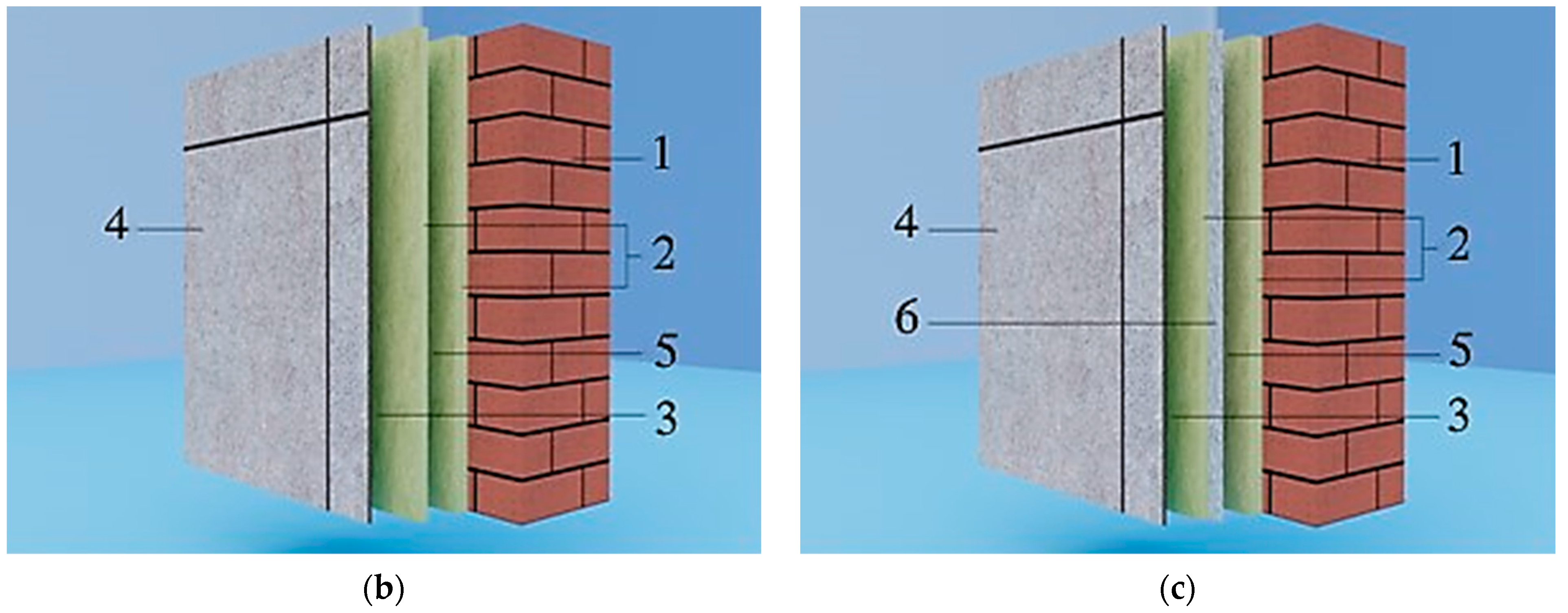
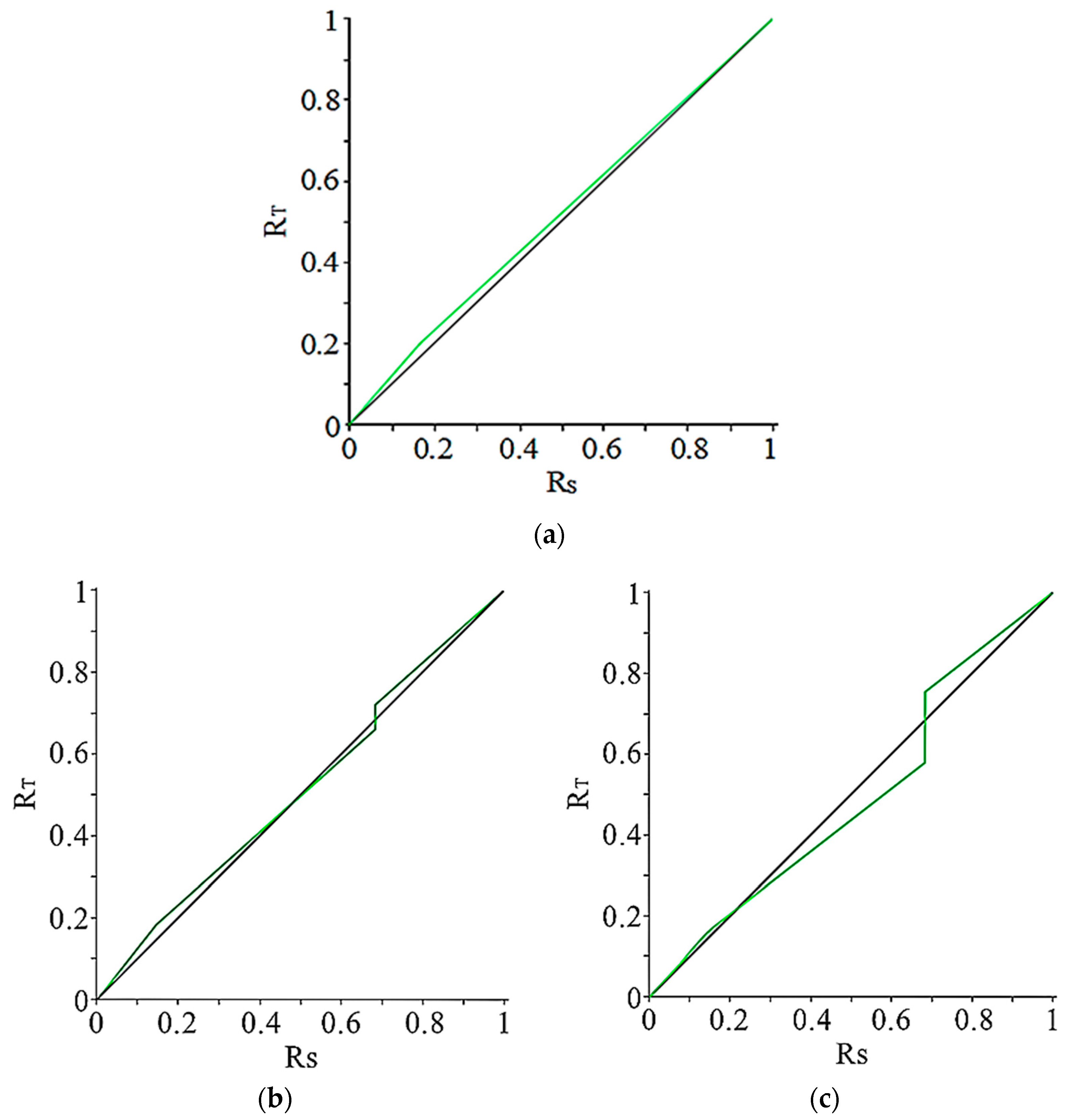
  • The value of vapor permeation demonstrated that the steam permeation strength of the internal side and protection fence of the worked-out structures is equal to that of the traditional one. Furthermore, the usage of the locked air space with a thermal reflecting screen allows the appropriate condensation zone to be shifted towards the open-air surface of the protection fence.
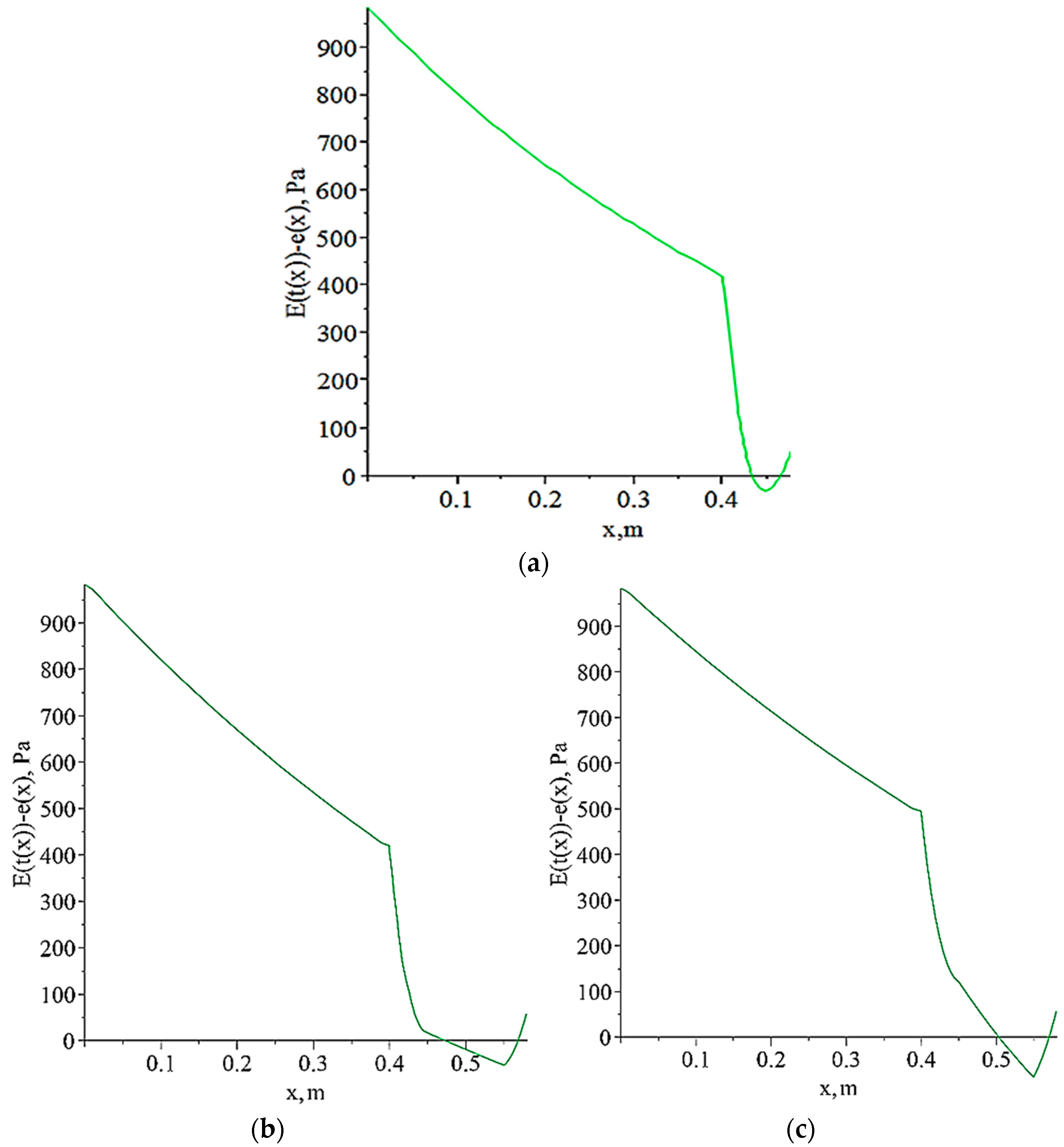
  • An analysis of structures proved that the condensation of water vapor occurs in the face protection fences. The widest condensation zone is in the face structure without heat-reflecting screens. In both face structures, the condensation zone begins in the closed gap spacing and terminates in the warmth-keeping jacket adjacent to the ventilated air spacing.
  • An analysis of the masses of condensed vapor for the heating time in 1 m2 of the protection fence showed that, in the face structures in the closed gap spacings with the presence of a thin layer of aluminum foil screen, the mass of the condensed vapor is 24.8% greater relative to the face without heat-reflecting screens.
  • A check of the absence of condensate in ventilated gap spacing demonstrated that the condensation does not fall into the gap spacing in all concerned face structures. For all schemes assumed, there was no accumulation of water content due to the year balance. Together, the drying time of the face structure with heat-reflecting screens was 17.9% longer.
  • An analysis of the requirement for air permeation without assuming the influence of the hinged face proved that this indicator is satisfied in all cases.

Author Contributions

Conceptualization, N.Z. and M.B.; methodology, N.Z., I.B., A.U. and T.T.; investigation, N.Z.; data curation, N.Z. and M.B.; writing—original draft preparation, N.Z.; writing—review and editing, N.Z. and M.B.; supervision, N.Z., I.B., A.U. and T.T.; project administration, N.Z.; funding acquisition, N.Z. All authors have read and agreed to the published version of the manuscript.

Funding

This article was funded by the Mukhtar Auezov South Kazakhstan University. M.B. would like to thank the National Science and Technology Council (NSTC) of Taiwan under the framework of the project “Recruitment of Visiting Science and Technology Personnel” (NSTC 112-2811-E-002-046-MY2) for their financial support.

Data Availability Statement

Data are contained within the article.

Conflicts of Interest

The authors declare no conflict of interest.

References

  1. UNDP. World Energy Assessment (WEA); UNDP: New York, NY, USA, 2000; Available online: https://web.archive.org/web/20201112004050/http://www.undp.org/content/dam/aplaws/publication/en/publications/environment-energy/www-ee-library/sustainable-energy/world-energy-assessment-energy-and-the-challenge-of-sustainability/World%20Energy%20Assessment-2000.pdf (accessed on 2 November 2023).
  2. Vandenbogaerde, L.; Verbeke, S.; Audenaert, A. Optimizing building energy consumption in office buildings: A review of building automation and control systems and factors influencing energy savings. J. Build. Eng. 2023, 76, 107233. [Google Scholar] [CrossRef]
  3. Code of Rules of the Republic of Kazakhstan 2.04-04-2011. Thermal Protection of Buildings: State Standards in the Field of Architecture, Urban Planning and Construction. Code of Rules of the Republic of Kazakhstan—JSC “KazNIISA”, LLP “Astana Stroy-Consulting”, 2013. Approved and Enacted on 1 July 2015; 14p. Available online: https://hoffmann.kz/files/12_SN_RK_2-04-04-2011.pdf (accessed on 2 November 2023).
  4. Code of Rules of the Republic of Kazakhstan 2.04-107-2013. Building Heat Engineering: State Standards in the Field of Architecture, Urban Planning and Construction. Code of Rules of the Republic of Kazakhstan—JSC “KazNIISA”, LLP “Astana Stroy-Consulting”, 2013. Approved and Enacted on 1 July 2015; 80p. Available online: https://continent-online.com/Document/?doc_id=38080689 (accessed on 5 September 2023).
  5. Code of Rules of the Republic of Kazakhstan 2.04-106-2012. Design of Thermal Protection of Buildings: State Standards in the Field of Architecture, Urban Planning and Construction. Code of Rules of the Republic of Kazakhstan—JSC “KazNIISA”, LLP “Astana Stroy-Consulting”. 2013. Approved and Enacted on 1 July 2015; 74p. Available online: https://online.zakon.kz/Document/?doc_id=35957424 (accessed on 5 September 2023).
  6. National Building Code (of Finland). Decree of the Ministry of the Environment on the Amendment of the Regulation 1.2 of the Degree on the Indoor Climate and Ventilation. 2003. Available online: https://build-up.ec.europa.eu/sites/default/files/D2eng%20-ventilation%20guidelines%20in%20Finalnd%20%20in%20English_p.pdf (accessed on 2 November 2023).
  7. Code of Rules of the Russian Federation 50.13330.2012 Thermal Performance of the Buildings. Available online: https://minstroyrf.gov.ru/docs/1882/ (accessed on 2 November 2023).
  8. Matic, D.; Calzada, J.R.; Eric, M.; Babin, M. Economically feasible energy refurbishment of prefabricated building in Belgrade, Serbia. Energy Build. 2015, 98, 74–81. [Google Scholar] [CrossRef]
  9. Roosmalen, M.; Herrmann, A.; Kumar, A. A review of prefabricated self-sufficient facades with integrated decentralised HVAC and renewable energy generation and storage. Energy Build. 2021, 248, 111107. [Google Scholar] [CrossRef]
  10. Pelletier, K.; Wood, C.; Calautit, J.; Wu, Y. The viability of double-skin façade systems in the 21st century: A systematic review and meta-analysis of the nexus of factors affecting ventilation and thermal performance, and building integration. Build. Environ. 2023, 228, 109870. [Google Scholar] [CrossRef]
  11. Zhangabay, N.; Kudabayev, R.; Mizamov, N.; Imanaliyev, K.; Kolesnikov, A.; Moldagaliyev, A.; Umbitaliyev, A.; Kopzhassarov, B.; Fediuk, R.; Merekeyeva, A. Study of the model of the phase transition envelope taking into account the process of thermal storage under natural draft and by air injection. Case Stud. Constr. Mater. 2023, 18, e02050. [Google Scholar] [CrossRef]
  12. Kudabayev, R.; Mizamov, N.; Zhangabay, N.; Suleimenov, U.; Kostikov, A.; Vorontsova, A.; Buganova, S.; Umbitaliyev, A.; Kalshabekova, E.; Aldiyarov, Z. Construction of a model for an enclosing structure with a heat-accumulating material with phase transition taking into account the process of solar energy accumulation. East.-Eur. J. Enterp. Technol. 2022, 6, 26–37. [Google Scholar] [CrossRef]
  13. Zhangabay, N.; Tagybayev, A.; Baidilla, I.; Sapargaliyeva, B.; Shakeshev, B.; Baibolov, K.; Duissenbekov, B.; Utelbayeva, A.; Kolesnikov, A.; Izbassar, A.; et al. Multilayer external enclosing wall structures with air gaps or channels. J. Compos. Sci. 2023, 7, 195. [Google Scholar] [CrossRef]
  14. Suárez, M.J.; Sánchez, M.N.; Blanco, E.; Jiménez, M.J.; Giancola, E. A CFD Energetic study of the influence of the panel orientation in Open Joint Ventilated Façades. Energy Rep. 2022, 8, 665–674. [Google Scholar] [CrossRef]
  15. ANSYS Learning—Thermal Convection in Heat Transfer—Assess Mode. Available online: https://courses.ansys.com/index.php/courses/thermal-convection-in-heat-transfer/ (accessed on 1 November 2023).
  16. Cholewa, T.; Balaras, C.A.; Nižetić, S.; Siuta-Olcha, A. On calculated and actual energy savings from thermal building renovations—Long term field evaluation of multifamily buildings. Energy Build. 2020, 223, 110145. [Google Scholar] [CrossRef]
  17. Gagliano, A.; Aneli, S. Analysis of the energy performance of an opaque ventilated façade under winter and summer weather conditions. Sol. Energy 2020, 205, 531–544. [Google Scholar] [CrossRef]
  18. Marinosci, C.; Semprini, G.; Morini, G.L. Experimental analysis of the summer thermal performances of a naturally ventilated rainscreen façade building. Energy Build. 2014, 72, 280–287. [Google Scholar] [CrossRef]
  19. Rahiminejad, M.; Pâris, A.; Ge, H.; Khovalyg, D. Performance of lightweight and heavyweight building walls with naturally ventilated passive and active facades. Energy Build. 2022, 256, 111751. [Google Scholar] [CrossRef]
  20. Buratti, C.; Palladino, D.; Moretti, E.; Di Palma, R. Development and optimization of a new ventilated brick wall: CFD analysis and experimental validation. Energy Build. 2018, 168, 284–297. [Google Scholar] [CrossRef]
  21. Alaidroos, A.; Krarti, M. Numerical modeling of ventilated wall cavities with spray evaporative cooling system. Energy Build. 2016, 130, 350–365. [Google Scholar] [CrossRef]
  22. Lin, Z.; Song, Y.; Chu, Y. An experimental study of the summer and winter thermal performance of an opaque ventilated facade in cold zone of China. Build. Environ. 2022, 218, 109108. [Google Scholar] [CrossRef]
  23. De Masi, R.F.; Festa, V.; Gigante, A.; Ruggiero, S.; Vanoli, G.P. Experimental analysis of grills configuration for an open joint ventilated facade in summertime. J. Build. Eng. 2022, 54, 104608. [Google Scholar] [CrossRef]
  24. Yu, J.; Yang, J.; Xiong, C. Study of dynamic thermal performance of hollow block ventilated wall. Renew. Energy 2015, 84, 145–151. [Google Scholar] [CrossRef]
  25. Borodulin, V.Y.; Nizovtsev, M.I. Modeling heat and moisture transfer of building facades thermally insulated by the panels with ventilated channels. J. Build. Eng. 2021, 40, 102391. [Google Scholar] [CrossRef]
  26. Fernández, C.; Vivancos, J.; Pablo, F.; Rafael, R. Energy performance of a ventilated façade by simulation with experimental validation. Appl. Therm. Eng. 2014, 66, 563–570. [Google Scholar] [CrossRef]
  27. Asphaug, S.K.; Time, B.; Kvande, T. Moisture accumulation in building façades exposed to accelerated artificial climatic ageing—A complementary analysis to NT BUILD 495. Buildings 2021, 11, 568. [Google Scholar] [CrossRef]
  28. Gullbrekken, L.; Kvande, T.; Jelle, B.P.; Time, B. Norwegian Pitched Roof Defects. Buildings 2016, 6, 24. [Google Scholar] [CrossRef]
  29. Kvande, T.; Bakken, N.; Bergheim, E.; Thue, J.V. Durability of etics with rendering in Norway—Experimental and field investigations. Buildings 2018, 8, 93. [Google Scholar] [CrossRef]
  30. Lau, G.E.; Yeoh, G.H.; Timchenko, V.; Reizes, J.A. Numerical investigation of passive cooling in open vertical channels. Appl. Therm. Eng. 2012, 39, 121–131. [Google Scholar] [CrossRef]
  31. Umnyakova, N.P. Thermal protection of closed air gaps with reflecting thermal insulation. Zhilishchnoe Stroit. 2014, 2, 16–20. Available online: https://cyberleninka.ru/article/n/teplozaschita-zamknutyh-vozdushnyh-prosloek-s-otrazhatelnoyteploizolyatsiey (accessed on 5 September 2023).
  32. Ucar, A.; Balo, F. Effect of fuel type on the optimum thickness of selected insulation materials for the four different climatic regions of Turkey. Appl. Energy 2009, 86, 730–736. [Google Scholar] [CrossRef]
  33. Kaynaklı, O. A study on residential heating energy requirement and optimum insulation thickness. Renew. Energy 2008, 33, 1164–1172. [Google Scholar] [CrossRef]
  34. Dombaycı, O.A. The environmental impact of optimum insulation thickness for external walls of buildings. Build. Environ. 2007, 42, 3855–3859. [Google Scholar] [CrossRef]
  35. Zhangabay, N.; Baidilla, I.; Tagybayev, A.; Sultan, B. Analysis of thermal resistance of developed energy-saving external enclosing structures with air gaps and horizontal channels. Buildings 2023, 13, 356. [Google Scholar] [CrossRef]
  36. Zhangabay, N.; Baidilla, I.; Tagybayev, A.; Suleimenov, U.; Kurganbekov, Z.; Kambarov, M.; Kolesnikov, A.; Ibraimbayeva, G.; Abshenov, K.; Volokitina, I.; et al. Thermophysical indicators of elaborated sandwich cladding constructions with heat-reflective coverings and air gaps. Case Stud. Constr. Mater. 2023, 18, e02161. [Google Scholar] [CrossRef]
  37. Tagybayev, A.; Zhangabay, N.; Suleimenov, U.; Avramov, K.; Uspenskyi, B.; Umbitaliyev, A. Revealing patterns of thermophysical parameters in the designed energy—Saving structures for external fencing with air channels. East.-Eur. J. Enterp. Technol. 2023, 4, 32–43. [Google Scholar] [CrossRef]
  38. Code of Rules of the Republic of Kazakhstan 2.04-01-2017. Building Climatology: State Standards in the Field of Architecture, Urban Planning and Construction. Code of Rules of the Republic of Kazakhstan—JSC “KazNIISA”, LLP “Astana Stroy-Consulting”, 2017. Approved and Enacted on 20 December 2017. 43p. Available online: https://online.zakon.kz/m/document/?doc_id=37599018 (accessed on 6 September 2023).
  39. Kupriyanov, V.N.; Safin, I.S. Design of Thermal Protection of External Walls Taking into Account Water Vapor Condensation; Kazan State University of Architecture and Civil Engineering: Kazan, Russia, 2016; p. 32. Available online: https://www.kgasu.ru/upload/iblock/d13/Proektirovanie-teplozashchity-naruzhnykh-sten-s-uchetom-kondensatsii-vodyanogo-para.pdf (accessed on 18 September 2023).
  40. Ślusarek, J.; Orlik-Kożdoń, B.; Bochen, J.; Muzyczuk, T. Impact of the imperfection of thermal insulation on structural changes of thin-layer façade claddings in ETICS. J. Build. Eng. 2020, 32, 101487. [Google Scholar] [CrossRef]
  41. Is the Wall All Wet? How to Avoid the “Dew Point” and Choose Insulation. 2020. Available online: https://dzen.ru/media/id/5c891947c35b2c00b3aee308/stena-vsia-namokla-kak-izbejat-tochki-rosy-i-vybrat-uteplitel-5e1cd2233d008800afe2d6c1 (accessed on 30 August 2023).
  42. Isachenko, V.P.; Osipov, V.A.; Sukomel, A.S. Heat Transfer; M.: Energoizdat: Moscow, Russia, 1975; p. 488. Available online: https://djvu.online/file/BXpZJMYm45EsC (accessed on 30 August 2023).
  43. Gagarin, V.G. About some thermal engineering mistakes made when designing ventilated facades. ABOK 2005, 2, 52–60. Available online: https://www.abok.ru/for_spec/articles.php?nid=2785 (accessed on 28 June 2023).
Figure 1. New worked-out face structures with continuous gap spacings. (a) With gap spacings: 1. load-bearing layer of brick fencing, 380 mm; 2. thermal insulation material made of expanded polystyrene, 50 and 30 mm; 3. ventilated air interlayer, 100 mm; 4. facing screen made of gray porcelain stoneware, 10 mm; and 5. closed air gap, 100 mm [35,36]. (b) With gap spacings and heat-reflecting screen in the open-air surface of the closed gap spacing: 1. load-bearing layer of brick fencing, 380 mm; 2. thermal insulation material made of expanded polystyrene, 50 and 30 mm; 3. ventilated air interlayer, 100 mm; 4. facing screen made of gray porcelain stoneware, 10 mm; 5. closed air gap, 100 mm; and 6. thin layer of aluminum foil screen [35,36]. (c) Traditional construction [37]: 1. load-bearing layer of brick fencing, 380 mm; 2. thermal insulation material made of expanded polystyrene, 80 mm; 3. ventilated air interlayer, 200 mm; and 4. facing screen made of gray porcelain stoneware, 10 mm [35,36].
Buildings 13 02853 g001aBuildings 13 02853 g001b
Figure 2. Type of dependence R T ˜ R s ˜ for the section of the closed gap spacing for the protection fence schemes: (a)—traditional construction [37]; (b)—with gap spacings; and (c)—with gap spacings and heat-reflecting screen in the open-air surface of the closed gap spacing.
Buildings 13 02853 g002
Figure 3. Dependence E t x e x for schemes: (a)—traditional construction [37]; (b)—with gap spacings; and (c)—with gap spacings and heat-reflecting screen in the open-air surface of the closed gap spacing.
Buildings 13 02853 g003
Table 1. Results of calculating the heat tolerance of enclosing structures.
Traditional Construction [37]With Gap SpacingsWith Gap Spacings and Heat-Reflecting Screen in the Open-Air Surface of the Closed Gap Spacing
D A ,
(J·m−2К−1s−1/2)
6.235
D B ,
(J·m−2К−1s−1/2)
-6.2356.235
A τ , A d e s , °C0.021
A τ , B d e s , °C-0.01950.0153
D A , D B —thermal inertia in section of gap spacing and continuous insulation, J·m−2К−1s−1/2; A τ , A d e s , A τ , B d e s —temperature amplitudes of fluctuations in the section of the continuous insulation and gap spacing, °C. The gap spacings do not affect the thermal inertia of the protection fence, and its parameters depend only on the total thickness of the material. At the same time, the thermal inertia of the worked-out structures (Figure 1b,c) is equal to that of the traditional (Figure 1a) one according to Tagybayev et al. [37]. The amplitude of the temperature fluctuations of the worked-out structures with gap spacings without heat-reflecting screens is 7.14% lower, while the presence of a thin layer of aluminum foil screen reduces this value to 27.14%. It should be noted that the sequence of the materials does not play a role.
Table 2. The vapor permeation resistance of protection fences for different schemes.
ValueTraditional Construction [37], m2·h·Pa/mgWith Gap Spacings, m2·h·Pa/mgWith Gap Spacings and Heat-Reflecting Screen in the Open-Air Surface of the Closed Gap Spacing, m2·h·Pa/mg
R A 18.937
R B -18.93718.937
R ¯ A 18.941
R ¯ B -18.94118.941
R A —the vapor permeation resistance of the inner wall of the protection fence in the section of continuous insulation; R B —the vapor permeation resistance of the inner wall of the protection fence in the section of air channel; R ¯ A —the vapor permeation resistance of the protection fence in the section of continuous insulation; and R ¯ B —the vapor permeation resistance of the protection fence in the section of the air channel. The characteristic of the vapor permeation resistance of the protection fence weakly characterizes the possibility of condensation falling inside it because it does not depend on the order of the layers. To qualitatively study this possibility, the dependence R T ˜ R s ˜ was constructed according to Tagybayev et al. [35]. The area between the two curves qualitatively characterizes the amount of the condensate in the protection fence: the larger the area above the curve R T ˜ = R s ˜ , the more condensate falls in the protection fence (Figure 2).
Table 3. Location of the condensation zone in the protection fence.
SchemeDew Point Temperature in the Section of Solid Insulation/Gap Spacing, °C Beginning   of   the   Condensation   Zone   x к 1 , m, in the Section of Solid Insulation/Gap Spacing End   of   the   Condensation   Zone   x к 2 , m, in the Section of Solid Insulation/Gap Spacing
Traditional construction [37]1/–0.4355/–0.4670/–
With gap spacings–/–3.12–/0.4718–/0.5688
With gap spacings and heat-reflecting screen in the open-air surface of the closed gap spacing–/–3.03–/0.5032–/0.5704
Table 4. The water vapor condensation in the protection fence.
Scheme Mass   of   Condensed   Vapor   during   the   Heating   Period   m , g, in 1 m2 of Solid Insulation/Gap Spacing SectionRelative Mass of Condensed Vapor during the Heating Period in the Insulation Layer, %Mass of Condensed Vapor during the Heating Period in 1 m2 of the Protection Fence, g
Traditional construction [37]31.44/–1.5731.44
With gap spacings–/150.373.81150.37
With gap spacings and heat-reflecting screen in the open-air surface of the closed gap spacing–/199.985.80199.98
Table 5. The results of checking for the absence of condensate in the ventilated gap spacing.
Scheme Vapor   Elasticity   in   the   Gap   Spacing   e п р , Pa Saturated   Vapor   Pressure   E t н , PaPresence of Condensate in the Gap Spacing
Traditional construction [37]153.926214.615-
With gap spacings153.921216.335
With gap spacings and heat-reflecting screen in the open-air surface of the closed gap spacing153.921215.852
Table 6. The water vapor condensation in the thickness of the protection fence.
SchemeDrying Rate in the Section of Solid Insulation /Gap Spacing, g/dayDrying Time in the Section of Solid Insulation Gap Spacing, DaysDrying Time of the Protection Fence, Days
Traditional construction [37]7.86/–4.0/–4.0
With gap spacings–/6.982–/21.521.5
With gap spacings and heat-reflecting screen in the open-air surface of the closed gap spacing–/7.638–/26.226.2
Table 7. Required air permeation resistance for different protection fence schemes.
Scheme R i n f r e q without   Taking   into   Account   the   Ventilated   Gap   Spacing ,   m 2 h · P a / k g R u in   the   Sec tion   of   Solid   Insulation ,   m 2 h · P a / k g R u on   the   Sec tion   of   Gap   Spacing ,   m 2 h · P a / k g
Traditional construction [37]60911
With gap spacings60911
With gap spacings and heat-reflecting screen in the open-air surface of the closed gap spacing60911
Disclaimer/Publisher’s Note: The statements, opinions and data contained in all publications are solely those of the individual author(s) and contributor(s) and not of MDPI and/or the editor(s). MDPI and/or the editor(s) disclaim responsibility for any injury to people or property resulting from any ideas, methods, instructions or products referred to in the content.

