1. Introduction
Closed steel sections are commonly used as structural members due to their superior advantages [
1,
2,
3], including increased stiffness, resistance to torsion, and improved load-carrying capacity compared to open sections. Concrete is sometimes filled inside the closed section. For example, concrete-filled steel tubes (CFSTs) have gained significant popularity in the construction of high-rise buildings due to their unique combination of structural efficiency, durability, and aesthetic appeal. CFSTs are composite structural components that consist of an outer steel tube filled with high-strength concrete. The combination of steel and concrete results in a composite section that efficiently utilizes the high tensile strength of steel and the superior compressive strength of concrete [
4,
5,
6]. This makes CFSTs capable of withstanding high vertical and lateral loads, ensuring the structural stability and integrity of tall buildings [
7,
8].
One of the critical issues in the design of CFSTs is the connection to the steel beams [
9,
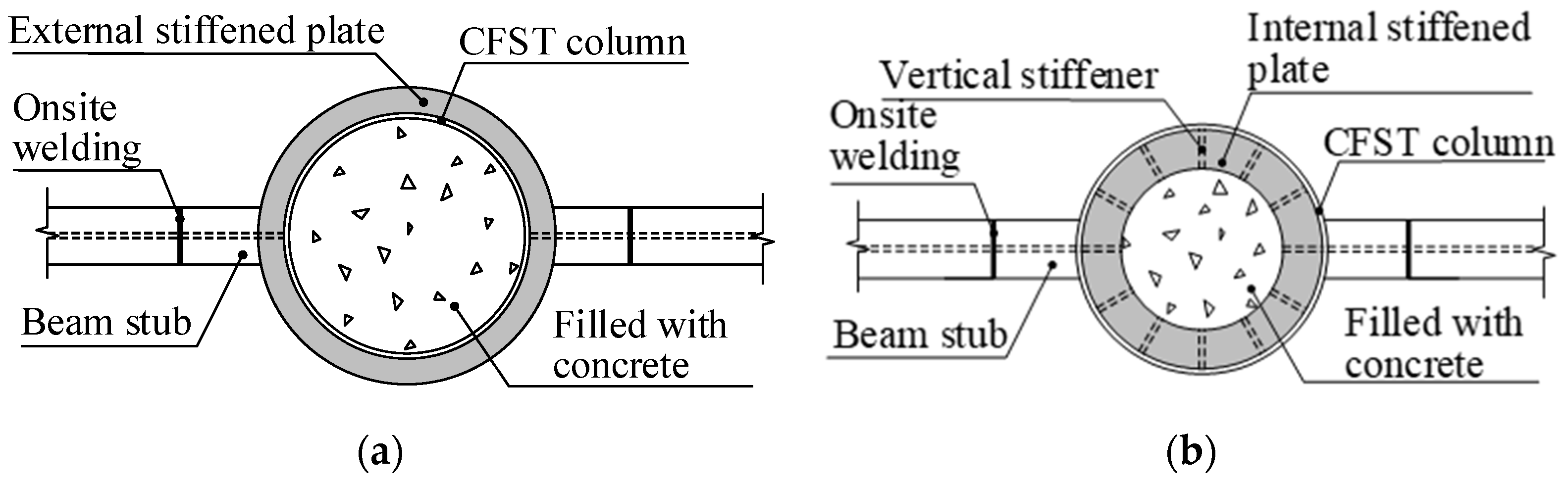
10]. Typically, reinforced plates are welded at the connection region to facilitate the ease of connecting steel beams and a smooth load transformation. Based on the location of the reinforced plates, there are three reinforcing forms in the CFST column to steel beam connection: external stiffened, internal stiffened, or both, as shown in
Figure 1. The external strengthened ring connection is currently the most mature and widely applied type of connection. The working principle of this type of connection is to install strengthened ring-shaped plates at the upper and lower flanges of the steel beam, which are connected to the flanges using equal-strength butt welds or high-strength bolts. The shear force is transferred through vertical rib plates connected to the steel beam web. The external strengthened connection has advantages such as a clear and direct force transfer path, uniform stress distribution in the connection region, high stiffness, good plastic performance, and a high load-bearing capacity. Its main drawback is that the reinforced plate usually protrudes from the column perimeter too much, which affects the architectural aesthetics. The internal strengthened connections have the stiffened plates welded inside the tube, aligning its position with the top and bottom flanges of the steel beam, as shown in
Figure 1. This type of connection can overcome the disadvantage of the external strengthened connection. The drawback of the internal strengthened stiffened connection is that it could interfere with pouring concrete inside the tube, and the welding work inside the tube is more complex. In particular, when the tube diameter is small, and the working space is limited, welding becomes extremely challenging.
The reinforced plates have a significant role in the behavior of the connection. Their behavior has been widely investigated. For example, Wang et al. [
11] examined the seismic performance of connections between reduced beam section (RBS) steel beams and CFST columns using an external ring connection, and the experimental results demonstrated that RBS connections with an external ring exhibited favorable behavior, including improved energy dissipation compared to weak-column connections. Shin et al. [
12] found that connections reinforced with T-stiffeners showed stable hysteretic behavior and good ductility. Numerous studies have been carried out on inner stiffening ring connection. Choi et al. [
13] conducted a study on through-ring plate connections, where the inner ring plate penetrates the steel tube in both directions. The study found that the connection performance improved as the thickness of the reinforcement ring increased. Elremaily and Azizinamini [
14,
15] designed seven connection specimens with inner stiffening rings but without vertical stiffening ribs for an experimental investigation. The results demonstrated that internal strengthening rings effectively improved the connection stiffness. Li [
16] investigated the stiffness of an inner ring connection using finite element simulation and revealed that the distance and width between the upper and lower ring plates had a significant influence on the connection stiffness. Zhao et al. [
17] designed three connection specimens with inner rings. Two of these specimens were equipped with stiffening rings only at the corresponding lower flange of the beam, while the other one had stiffening rings at both the upper and lower flanges. Experimental tests showed that the connections with two reinforcement rings exhibited a higher load carrying capacity and ductility. Wang [
18] conducted an experimental study and finite element analysis on inner stiffening ring connections and suggested that the width of the inner ring plate should be taken as 0.6–0.8 times the width of the beam flange.
The load that is carried by the steel beam is ultimately distributed throughout the cross section of the tube. Initially, the load is transferred to the tube wall of the column, where the steel beam is attached. Through the column, it is transmitted downward to the foundation by the composite action of the steel tube and the concrete core. The transfer of the load is complex at the connection region, with one of the challenges being the bonding strength between the steel tube and the concrete interface [
19].
There are various challenges that arise due to the large size of the steel tube and the volume of concrete associated with it. Factors such as concrete shrinkage and creep, as well as the poor compaction of the concrete in the connection region, can all contribute to difficulties in ensuring a reliable bond between the steel tube and the concrete. Additionally, the steel tube often has a thin wall thickness in comparison to its diameter, resulting in a high diameter-to-thickness ratio.
When loads are transferred from the beam to the column, it is important to have sufficient concrete in the vicinity of the connection to effectively share the load-bearing responsibilities. Insufficient concrete participation in load transfer can lead to undesirable effects such as tensile cracking or the compressive buckling deformation of the steel tube wall. As a result, the shear forces from the beam may not be adequately transmitted downward.
Recently in China, the Wuhan Center Tower [
20,
21], a super high-rise building, was constructed using a tube-frame structural system with outriggers. To provide strength and support, large diameter CFST (3000 mm) columns were utilized as frame columns. Reinforced plates were welded inside the columns at the connecting area of the steel beams. However, due to limited available data on the design of connections involving such large diameter CFST columns, this study aims to evaluate the behavior of these columns. Specifically, the transfer mechanism and the influence of component parameters on the load transfer path and stress distribution of the composite sections are analyzed. The results obtained from both the experimental tests and numerical study are instrumental in guiding the design of similar projects.
4. Parametric Study and Discussion
Figure 7 depicts the transfer mechanism of the vertical load (F) from the beam to the CFST column. This load is ultimately supported by the exterior steel tube (F
s) and the core concrete (F
c,SUM), as shown in
Figure 7a. There are two paths by which the load is conveyed to the interior concrete (
Figure 7b). Firstly, it is transferred through the contact force (F
f) between the steel tube and the concrete. Secondly, it is transferred through the compression force (F
R) exerted by the inner ring plates. The sum of these two forces equals the axial force of the concrete (F
c,SUM). In this study, the load bearing ratio of these two components (i.e., F
f and F
R) is defined as the proportion of their load in relation to the total load (F) of the CFST column.
The validated FE model was used to perform an extensive parametric study on the CFST column to steel beam connections. Based on the experimental results, the inner ring plates and vertical stiffeners mainly affect the stiffness of the connection. Therefore, a parametric study was conducted with a focus on investigating the friction coefficient, the ring plate width, ring plate thickness, and vertical stiffness thickness on the load transfer from the steel beam to the core concrete. All the models had the same column size of 750 × 16 (outer diameter × wall thickness, unit: mm), and same beam size of 285 × 200 × 20 × 20 (depth × width × web thickness × flange thickness, unit: mm). The beam length from the column face was 400 mm. The investigated parameters were the inner ring plate size (width D
r, and thickness t
r), the vertical stiffener thickness t
v, and the friction coefficient μ. The specific values are summarized in
Table 2. A total of 44 models were analyzed.
Figure 8 shows the details of the investigated parameter.
4.1. Influence of the Friction Coefficient on the Load Distribution
In engineering practice, it has been observed that the desired bonding condition may not be achieved in the contact between the steel pipe wall and the concrete. This contact situation is influenced by several factors, including the quality of concrete pouring and curing. Particularly in large-diameter steel pipe concrete columns, certain conditions such as thermal expansion and contraction can result in a very weak friction situation between the steel pipe and the concrete. Consequently, the inner ring plates would take the majority of the force, then transferring the load to the concrete.
Series 1 models in
Table 1 were used to analyze the influence of the friction coefficient on the load distribution. Two distinct geometry models were developed, one with a thin ring plate and another with a thick ring plate. The width of the ring plate was 75 mm and the thickness of the vertical stiffener was 16 mm. For each model, a large range of friction coefficients (μ = 0.01, 0.05, 0.10, 0.15, 0.20, 0.25) was applied.
As described in
Figure 7, the force taken by the concrete comes from two components, namely F
f and F
R. The load bearing ratio of F
f and FR can be defined as F
f/F and FR/F, respectively.
Figure 9 shows the load bearing ratio of these two components. The horizontal axis denotes the friction coefficients, while the vertical axis represents the load bearing ratio. In the figure, the legend “F
f/F” represents the load bearing ratio of F
f (F
f/F), “F
R/F” represents the load bearing ratio of F
R (F
R/F), and “F
c,sum” represents the sum of the two, which is the total proportion of the load borne by the concrete.
As can be seen from the Figure, when both the inner ring plate and frictional force are present, they can transfer a certain proportion of vertical load to the core concrete. As the friction between the steel tube wall and concrete decreases, the proportion of the load transmitted to the core concrete through the inner ring plate gradually increases. However, when the frictional contact cannot be guaranteed (e.g., friction coefficient μ = 0.01), the inner ring plate would transfer a significant proportion of load to the concrete, and the total sum of the load transmitted by both the inner ring plate and frictional force remains basically unchanged, with only a slight increase as the friction coefficient increases. By comparing
Figure 9a,b, it can be observed that when the friction coefficient is large, increasing the thickness of the inner ring plate will not significantly increase the total load transmitted from the steel beam to the core concrete. However, when the thickness of the ring plate increases, the compression force exerted by the inner ring plates (F
R), becomes more prominent. This means that a thicker ring plate will play a more significant role in transferring the load to the interior concrete compared to the contact force between the steel tube and the concrete. In conclusion, when both frictional force and the inner ring plate are present, they can effectively transfer vertical load to the core concrete, and the ratio of vertical load transmission will vary according to their respective capabilities. When the contact between the steel tube wall and concrete cannot be guaranteed, the inner ring plate can transfer almost the same proportion of vertical load to the core concrete.
4.2. Influence of the Ring Plate Width on the Load Distribution
Series 2 models in
Table 1 were used to analyze the influence of the ring plate width on the load distribution. The inner ring plate width parameters were selected as Dr = 3 mm, 5 mm, 10 mm, 25 mm, 50 mm, 75 mm, 100 mm, 150 mm, and 187.5 mm. The inner ring plate thickness was taken as 16 mm and 8 mm. The friction coefficient was taken as 0.01.
The results are shown in
Figure 10, where the horizontal axis represents the width of the inner ring plate, and the vertical axis φ represents the load bearing ratios. Specifically, UR represents the load bearing ratio of the inner ring plate at the top flange, DR represents the load bearing ratio of the inner ring plate at the bottom flange, and SUM represents the sum of the two. As can be seen from the Figure, when the width of the inner ring plate was not greater than 10 mm, the load bearing ratio through the top and bottom inner ring plates increased rapidly with the increase in the ring plate width. The load bearing ratio of the top ring plate was higher than that of the bottom ring plate. When the width of the inner ring plate exceeded 25 mm, the load bearing ratio of the top ring plate decreased as the width of the plate increased. However, the load bearing ratio of the bottom ring plate still gradually increased as the width of the plate increased. When the plate width reached to 150 mm, the load bearing ratio stabilized at a constant level, indicating the maximum bearing capacity of the ring plates.
It is a bit abnormal that the load bearing ratio of the top ring plate decreased as its plate width increased. Through the examination of the deformed shape of the tube, it was discovered that the tube wall deformed extensively at the vicinity of the upper ring plate. When the width of the ring plate was small (e.g., tr = 16 mm, Dr ≤ 50 mm), the ring plate was so weak that the tube wall was pulled out from the concrete due to the tension in the steel beam’s top flange, causing the connection to rotate downward around point O (
Figure 11). Therefore, the embedded length of the upper ring plate would reduce, resulting in a very limited contact area with the core concrete. Consequently, the load bearing capacity of the upper ring plate was limited.
When the width of the ring plate was relatively small (e.g., tr = 16 mm, Dr = 10~25 mm), there would be detachment between the steel tube wall and the core concrete. In this case, the weak stiffness failed to meet the design requirements for bending moments. When the width of the ring plate was excessively large, such as 75 mm to 187.5 mm, the load bearing capacity of the ring plates would not increase significantly. Based on the above analysis, the optimal width of the inner annular plate would be 75 mm. This was the chosen width for the subsequent analysis.
4.3. Influence of the Ring Plate Thickness on the Load Distribution
Series 3 models in
Table 1 were used to analyze the influence of the ring plate thickness on the load distribution. When studying the influence of the thickness of the inner ring plate on the load distribution, other parameters were kept constant, such as the width of the ring plate at 75 mm and the thickness of the vertical rib at 16 mm. The thickness of the inner ring plate ranged from 6 mm, 8 mm, 10 mm, 12 mm, and 16 mm, to 20 mm. A friction coefficient of 0.01 remained constant for all the models.
Figure 12 shows the computational results. Note UR represents the load bearing ratio of the inner ring plate at the top flange, DR represents the load bearing ratio of the inner ring plate at the bottom flange, and SUM represents the sum of the two. When the thickness of the ring plate increased from 6 mm to 20 mm, the total load bearing ratio increased from 45% to 52%. It seems that the thickness of the ring plate was not the critical factor affecting the transmission of vertical loads. In engineering design, the determination of the inner annular plate thickness can be based on the bending moments of the steel beam.
4.4. Influence of the Vertical Stiffener Thickness on the Load Distribution
Series 4 models in
Table 1 were used to analyze the influence of the vertical stiffener on the load distribution. The thickness parameter of the vertical stiffeners was set as tv = 6 mm, 8 mm, 10 mm, 12 mm, 16 mm, and 20 mm. As shown in
Figure 13, when the thickness of the vertical stiffeners increased from 6 mm to 20 mm, the vertical load transmitted from the inner ring plate to the internal concrete actually decreased slightly. Note UR represents the load bearing ratio of the inner ring plate at the top flange, DR represents the load bearing ratio of the inner ring plate at the bottom flange, and SUM represents the sum of the two. The explanation may be as follows: The inner ring plate transferred vertical loads by compressing the concrete through downward deformation. However, the presence of vertical stiffeners hindered the downward deformation of the local ring plate, as shown in
Figure 14. The thicker the vertical stiffeners, the more pronounced the hindrance, resulting in a reduction in the vertical load transferred from the inner ring plate to the concrete.
4.5. Influence of the Ring Plate Width on the Stress Transition Length
Figure 15 shows the Mises stress contour of the concrete. The concrete surrounding the ring plate was in a state of localized compression. An uneven stress distribution was observed: higher stress level in the region near the steel tube wall compared to the core region. In particular, on the cross section near the connection, the stress was unevenly distributed along the section. As the load was transmitted to a certain distance, the stress distribution on the section tended to become uniform. This distance was defined as the stress transition length. When the transition length is greater than the story height, the concrete near the tube wall may experience crushing due to the combined effect of the load from the upper floor and the current floor. This can lead to the buckling and failure of the pipe wall, resulting in serious consequences.
In the FE analysis, we assumed a uniform stress distribution when the error between the maximum and minimum stresses on the same section was less than 10%; that is, (σ
max − σ
min)/σ
max ≤ 10%. A short stress transition length indicated a faster and more uniform diffusion of stress within the concrete. Through a series of analysis and research, among the parameters studied in this paper, the width of the inner ring plate was the controlling parameter that affected the stress transition length. Series 5 models in
Table 1 were used to analyze the influence of the ring plate width on the stress transition length. The parameter values for the width of the inner ring plate (D
r) were chosen as 15 mm, 30 mm, 45 mm, 90 mm, and 180 mm, with a friction coefficient (μ) of 0.01.
Figure 16 shows the relationship between the stress transition length and the ring plate width. The stress transition distance ranged from 720 mm to 800 mm, approximately equal to the diameter of the steel tube. When the diameter of the steel pipe concrete column reached 3 m to 4 m in the real practice (i.e., Wuhan Center Tower), the stress transition length was still within the story height. Therefore, the occurrence of uneven stresses in the concrete cross section due to the combined loads of the upper floor and the present floor would not occur.
4.6. Influence of the Concrete Pouring Defects on the Load Distribution
The full contact between the steel tube and concrete ensures the excellent performance of steel-reinforced concrete columns, while concrete pouring is a crucial concern for the connections with inner ring plates. As demonstrated in the previous sections, the ring plate is one of the main components for transferring loads to the core concrete. If the quality of concrete pouring is not guaranteed or the concrete beneath the inner ring plate is not compacted, there would be significant gaps between the concrete and the inner ring plate, compromising the effectiveness of the load transmission.
Two types of pouring defects were considered in this study. One defect involves complete separation between the inner ring plate and the concrete beneath it, as shown in
Figure 17a. The separation was across the whole width of the ring plate. The other defect was less width separation with a width of 10 mm, representing partial separation in which a limited separation occurred only near the steel tube, as shown in
Figure 17b. Two separation distances were considered in each defect, i.e., 3 mm and 7 mm. The model information is summarized in Series 6 in
Table 2. Two types of column sections were adopted, 600 mm and 900 mm.
Table 3 lists the load bearing ratio of the concrete. The load bearing ratio of the concrete decreased significantly in complete separation. With a separation distance of 3 mm, the concrete only took 0.10 to 0.11 of the total load. With a larger separation distance of 7 mm, the load bearing ratio was reduced to 0.02, and the inner ring plate made almost no contribution to the transmission of the load. The steel tube would take almost all of the load, which deviated from the design concept that the concrete and steel tube bear the load together. On the other hand, in the case of partial separation defect, the separation distance did not have a significant influence on the load bearing ratio of the concrete. Although the exact ratio may be debated, the observed trend holds considerable significance. Therefore, when pouring concrete into steel columns with inner ring plates, strict control of the concrete pouring quality is necessary. It is recommended to use concrete with higher fluidity and smaller shrinkage. In addition, quality control measurements should be taken. For example, when pouring concrete near the connection region, it is necessary to pour continuously and properly compact the concrete by vibrating.
5. Conclusions
This study presented an experimental and numerical investigation on the behavior of concrete-filled steel tube (CFST) column to steel beam connections reinforced with internal ring plates. The aim was to evaluate the adequacy of this connection design used in a prototype high-rise building (i.e., the Wuhan Center Tower) and provide recommendations for enhancing similar connections.
The results showed that the composite action of the ring plate and friction together enabled effective transfer of vertical loads from the steel beam to the concrete core. Parametric analysis revealed that a ring plate width of around 75 mm provided an optimal load carrying capacity, while the plate thickness and vertical stiffener thickness had minor influence. Severe concrete defects beneath the ring plate significantly compromised its load transfer ability, highlighting the need for stringent quality control during concrete placement. It should be note that this research is motivated by the objective of offering design recommendations for the Wuhan Center Tower project. The optimal width of the inner ring plate is closely associated with the dimensions of the CFST column. This study has determined that the optimal width corresponds to 1/10 of the external diameter of the column. This find may also be a valuable reference for other similar cases.
The stress distribution in the concrete cross section was found to transition from nonuniform to uniform over a length approximately equal to the column diameter. This was within the acceptable limits for the prototype structure studied. Overall, the connection design with internal ring plate reinforcement was validated through this study for the loads and geometries analyzed.
These findings provide valuable insights into the behavior and design optimization of ring-plate-reinforced CFST column to steel beam connections. Further experimental and analytical research on large-scale connections under cyclic loading can help extend these results. The knowledge gained can guide safer and more efficient design of such connections in future high-rise construction.


