Article

Dissimilar Pile Raft Foundation Behavior under Eccentric Vertical Load in Elastic Medium

1
School of Civil Engineering, Chongqing Three Gorges University, Chongqing 404100, China
2
Sichuan Academy of Agricultural Sciences, Chengdu 610066, China
*
Authors to whom correspondence should be addressed.
Buildings 2023, 13(12), 3040; https://doi.org/10.3390/buildings13123040
Submission received: 28 October 2023 / Revised: 30 November 2023 / Accepted: 5 December 2023 / Published: 6 December 2023
(This article belongs to the Section Building Structures)

Abstract

:
Pile raft foundation (PRF) is a common foundation type for buildings and bridge piers which has been commonly subjected to eccentric vertical load in engineering applications. Dissimilar PRF is often adopted to reduce the excessive settlement and differential settlement of superstructures. The behavior of dissimilar PRF under eccentric vertical load is a significant issue and investigated with the boundary element method in this paper. In this method, the dissimilar pile–soil system is decomposed into extended soil elements and fictitious pile elements. The second kind of Fredholm integral governing equation of the axial force of fictitious piles is established based on the compatibility condition of axial strain between the extended soil and fictitious piles. An iterative procedure is adopted to analyze the average settlement w and rotation slope θ of raft stemming from the settlement compatibility condition of the top of each element and the equilibrium condition of the raft. Furthermore, the axial force and settlement of each element along its depth can be predicted. The corresponding results agree well with a reported case and the finite element method. The characteristics of 3 × 1 and 3 × 3 dissimilar PRFs under eccentric vertical load, including non-dimensional vertical stiffness N0/wEsd, differential settlement wd and the load sharing ratio of typical elements Ni/N0, are systematically investigated by considering different eccentricity e, length/diameter ratios of pile l/d and pile–soil stiffness ratio Ep/Es conditions. The N0/wEsd increases with l/d, while the load sharing ratios of the raft Nraft/N0 and wd decreases with l/d. The eccentricity e has a significant effect on wd and Ni/N0 and a neglect effect on N0/wEsd and Nraft/N0. The N0/wEsd, wd and Ni/N0 are significantly increased with Ep/Es. This research is expected to provide insights to the practitioners into the dissimilar PRF design under eccentric vertical load.

1. Introduction

Pile raft foundation (PRF) is one of the most common foundations for buildings and bridge piers [1], particularly for the weaker soil conditions, which has been frequently subjected to eccentric vertical load due to its irregular shape or moment loads from superstructures [2]. Therefore, PRF with dissimilar pile lengths has received considerable attention with the aim of reducing the excessive settlement and differential settlement of superstructures at a lower cost. The settlement characteristics of dissimilar PRF under eccentric vertical load are not well understood due to the complex interactions among the piles–soil–raft [3]. With the PRF designs that have been transformed from capacity-based criterion to serviceability-based criterion gradually, the threshold values of average and differential settlement are frequently induced to define the serviceability limit states. For instance, the displacement corresponding to 2%d for the master node is set to the serviceability state [4]. Therefore, it is imperative to accurately achieve the behavior of dissimilar PRF under eccentric vertical load within elastic theory.
The behavior of pile groups and PRFs under vertical load has been analyzed extensively over the past few decades, such as in full-scale field investigations [5,6], scale model testing [7,8,9] and theoretical analysis [10,11,12,13]. Many investigators have shown that the eccentric load has a significant effect on the bearing capacity of the foundation and failure mode due to highly non-uniform load sharing [14,15]. But many reported methods have focused mainly on the pile groups or PRFs’ behavior with equal pile lengths [8,16,17,18,19]. It can be expected that the consideration of dissimilar pile length may be more realistic in practical engineering. The boundary element method has been adopted to analyze the behaviors of pile groups and PRFs having dissimilar pile lengths under central load due to its high calculation efficiency and rigorousness [20,21]. There remains a distinct lack of research into the eccentrical load on dissimilar PRFs. Although FEM [19,22,23,24] can deal with the dissimilar pile length condition easily, the costs of such computations are rather prohibitive. There is an urgent need to provide simplified theoretical methods for dissimilar PRFs to capture the pile–soil–raft interaction effects and load sharing ratio mechanisms.
In this paper, the response of an n1 × n2 floating dissimilar PRF under eccentric vertical load is investigated. The sound analytical model is established, which is obtained by extending the method proposed by Muki and Sternberg [25]. First, the PRF is decomposed into the extended soil (m square elements) and n1 × n2 dissimilar fictitious piles with the pile diameter d. Then, the axial strain of extended soil can be obtained based on Mindlin’s solutions [26] and superposition principle, and the axial strain of fictitious piles can be achieved based on beam theory. The governing equation of the axial force of fictitious piles is established stemming from the axial strain compatibility at corresponding positions between the extended soil and fictitious piles. Therefore, the axial force and settlement expressions of all of the real pile and soil elements beneath the raft can be obtained. Because the vertical load of all of the element head is not known, the expressions mentioned above cannot be calculated directly. An iterative procedure about the vertical load of each element head is induced to solve those mentioned expressions and to estimate the behavior of all of the elements by combining the equilibrium conditions of eccentric vertical load and the displacement compatibility conditions of each element. Parametric research combining two cases is presented to show the influence of eccentricity e, pile length/diameter ratio l/d and pile/soil stiffness ratio Ep/Es on the PRF performance parameters such as non-dimensional vertical stiffness N0/wEsd, load sharing ratios of typical element Ni/N0 and the differential settlement wd.

2. Method of Analysis

An advanced analyzed model for PRFs is developed based on the boundary element method. The soil and piles are modeled as a weightless elastic material, and the wished-in-place installation of weightless piles and the raft is assumed. The settlements of pile heads are coupled to those of the corresponding elements in the rigid raft.

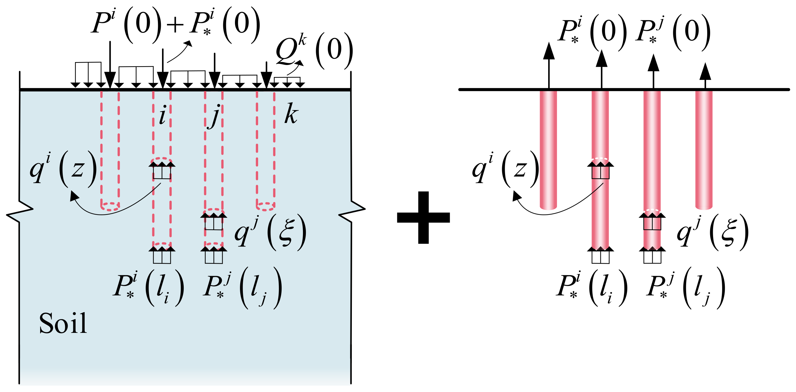
2.1. Analytical Model

The typical PRF with rectangular rafts and n (n = n1 × n2) dissimilar circular piles in homogeneous elastic medium is illustrated in Figure 1, and the coordinate system is also chosen, as Figure 1 indicates. n1 and n2 are the numbers of rows and columns for the pile configuration, respectively, d and s are the pile diameter and center-to-center distance of neighboring piles, li denotes the length of pile i, b indicates the clear overhang width of the cap as extended from the outer piles, and Es and Ep are the Young’s moduli of the soil and piles, respectively. Poisson’s ratio for the soil and piles are assumed to be the same and equal to ν to simplify the analysis. The applied eccentric vertical load is set to N0. The eccentricity e is the distance from the load point to the raft foundation center, and no tension stress zone between the raft and soil is allowed in regular PRF design; therefore, the range of e/B is considered from 0 to 1/6.
The PRF system is discretized into m square sub-elements based on the pile diameter. It is noted that n square sub-elements are occupied by the pile elements (red circle in Figure 1), and the remaining m-n square sub-elements are the soil elements.
Following the method proposed by Muki and Sternberg [27], the pile–soil system is decomposed into the extended soil and fictitious piles (Figure 2). And then, force analysis is performed considering the two systems separately. For the discretized m square sub-elements, the vertical load acting at the i-th pile head and k-th soil unit head are expressed as Pi(0) and Qk(0) (i = 1, 2, …, n, k = n + 1, n + 2, …, m), respectively. P * i z and qi(z) are the axial force and shaft resistance of the i-th fictitious pile at a depth z. Then, the load acting at the extended soil is obtained by considering the interaction force between two decomposed systems. For instance, P i 0 and P i l i are the axial force of the i-th fictitious pile head and bottom, and P i ( 0 ) + P i 0 and Qk(0) are the axial forces of the i-th and k-th extended soil unit head.

2.2. Fictitious Piles

Based on beam theory for fictitious piles, the stress–strain equation, equilibrium equation, and strain–displacement relationship of the i-th fictitious pile unit can be calculated as follows:
ε * i z = P * i z E A     ( 0 z l i , i = 1 , 2 , , n )
d P * i z d z = q i z     ( 0 z l i , i = 1 , 2 , , n )
ε * i z = d w * i z d z     ( 0 z l i , i = 1 , 2 , , n )
where ε i z , w i z and A denote the axial strain and settlement at a depth z and cross-sectional area for the i-th fictitious pile unit, respectively; E is the Young’s modulus of the fictitious pile unit and can be expressed as E = E p E s .

2.3. Extended Soil

For the extended soil, σ z r z , ε z r z and w z r z represent the vertical stress, vertical strain, and settlement in the region Π(z) at the position of the r-th (r = 1, 2, …, m) extended soil unit, which can be expressed by the superposition principle as follows:
σ z r z = j = 1 n P j 0 + P * j 0 σ z r j z , 0 P * j l j σ z r j z , l j 0 l j q j ξ σ z r j z , ξ d ξ + k = n + 1 m Q k 0 σ z r k z , 0   0 z l i
ε z r z = j = 1 n P j 0 + P * j 0 ε z r j z , 0 P * j l j ε z r j z , l j 0 l j q j ξ ε z r j z , ξ d ξ + k = n + 1 m Q k 0 ε z r k z , 0   0 z l i
w z r z = j = 1 n P j 0 + P * j 0 w z r j z , 0 P * j l j w z r j z , l j 0 l j q j ξ w z r j z , ξ d ξ + k = n + 1 m Q k 0 w z r k z , 0   0 z l i
where σ z r j z , ξ , ε z r j z , ξ and w z r j z , ξ are the influence coefficient of the average vertical stress, vertical strain, and settlement of the extended soil in the region Π(z) at the r-th unit due to the uniform distribution and unit load in the region Π(ξ) at the j-th fictitious pile unit, respectively.
The vertical stress and settlement influence coefficients are evaluated by integrating Mindlin’s solutions directly. Then, the vertical strain can be attained from the differential settlement influence solution.
A finite jump exists at z = ξ for σ z r j z , ξ and ε z r j z , ξ . The σ z r j z , ξ , ε z r j z , ξ and w z r j z , ξ can be derived by combining Equations (2) and (4)–(6) as follows:
σ z r z = P * i z σ z i i z , z σ z i i z , z + j = 1 n 0 l j P * j ξ σ z r j z , ξ ξ d ξ + j = 1 n P j 0 σ z r j z , 0 + k = n + 1 m Q k 0 σ z r k z , 0
ε z r z = P * i z ε z i i z , z ε z i i z , z + j = 1 n 0 l j P * j ξ ε z r j z , ξ ξ d ξ + j = 1 n P j 0 ε z r j z , 0 + k = n + 1 m Q k 0 ε z r k z , 0
w s r z = j = 1 n 0 l j P * j ξ w z r j z , ξ ξ d ξ + j = 1 n P j 0 w z r j z , 0 + l = n + 1 m Q l 0 w z r l z , 0
where ε z i i z , z + ε z i i z , z = ( 2 v 1 ) ( 1 + v ) E s A ( 1 v ) and σ z i i z , z + σ z i i z , z = 1 / A are obtained from the generalized Hook’s law and equilibrium equation, respectively.

2.4. Governing Integral Equations

The governing equation is established by imposing the strain average compatibility at corresponding depths between the fictitious piles and extended soil.
1 E * 1 2 v 1 + v E s 1 v P * i z + A j = 1 n 0 l j P * i ξ ε z i j z , ξ ξ d ξ = A j = 1 n P j 0 ε z i j z , 0 + k = n + 1 m Q k 0 ε z i k z , 0
This is known as the Fredholm integral equation of the second kind, where the axial forces of the fictitious pile are the unknown parameters. Transforming the integral equations mentioned above into algebraic equations is a common and relatively simple approach in order to obtain a reasonable solution. Suppose each element is divided into a series of equal length sub-elements. For instance, for the r-th element with sr − 1 segments of length lr/(sr − 1) and sr nodes, which means that the sr unknown parameters P j z α (α = 1, 2, …, sr) exist for the r-th element, the zα denotes the depth of the selected nodes in the r-th unit. Then, the total node number for n pile units is N 1 = r = 1 n s r , for the rest of the m-n soil units is N 2 = r = n + 1 m s r , and for all units is N = N1 + N2. Thus, Equation (10) can be recast into the following:
1 E * 1 2 v 1 + v E s 1 v P * i z χ + A j = 1 n α = 1 s j P * j z α ε z i j z χ , z α z α = A j = 1 n P j 0 ε z i j z χ , 0 + k = n + 1 m Q k 0 ε z i k z χ , 0
The meaning of index χ is the same as index α. Equation (11) is an algebraic equation containing N1 unknowns. For the conditions of pile group without the raft or with an absolute flexibility cap, the vertical loads of all unit tops are known; therefore, a definite solution can be obtained from Equation (11) and the load transfer mechanism and settlement characteristics for the pile group without the raft or with an absolute flexibility cap can be analyzed directly. For the PRF with a rigid cap, the vertical load of each unit top is unknown. Thus, the governing Equation (11) cannot be solved directly, and supplementary equations are needed.
Once the axial forces of all fictitious piles P i z (i = 1, 2, …, n) have been calculated, the real axial force of all units Pr(z) (r = 1, 2, …, m) can be expressed as the difference between P i z and σ z r z A :
P r z = A j = 1 n 0 l j P * j ξ σ z r j z , ξ ξ d ξ + A j = 1 n P j 0 σ z r j z , 0 + A k = n + 1 m Q k 0 σ z r k z , 0
Similarly, once P i z (i = 1, 2, …, n) have been obtained, the settlement of each extended soil can be calculated directly from Equation (9). The settlement of pile units w p i z are coincident with the extended soil in the corresponding position w s r z , which means that when r = i, we have the following:
w p i z = w s r z     ( r = i )
The load and settlement of each unit top Pr(0), w s r 0 can be obtained by supposing z = 0 in Equations (9) and (12).
The vertical stiffness for each element kr is defined as the ratio of Pr(0) to w s r 0 , so then, the following can be obtained:
k r = P r 0 / w s r 0     ( r   =   1 ,   2 ,   ,   m )

2.5. Supplementary Equations

Considering the effect of dissimilar pile length and eccentricity e, the differential settlement of PRF may exist. Therefore, the average settlement w and inclination slope θ of the raft are considered as the critical parameters for the PRF behavior, which should be compatible with the settlement of each unit top wr(0) (r = 1, 2, …, m).
The eccentric vertical load N0 is applied at the location (0, −e, 0). For the sake of clarity, the eccentric vertical load N0 is equivalent to the centric load N0 and negative moment Mx = −e × N0.
The vector Κ 1 × m is defined to represent the vertical stiffness of each element and can be written as Κ = k 1 , k 2 ,   ,   k m .
The vector Y 1 × m denotes the localization vector of the y-direction, which can be expressed as Y = y 1 , y 2 ,   ,   y m and readily obtained from the coordinate system of Figure 1.
The settlement vector of each unit top W m × 1 can also be expressed as W = w s 1 0 , w s 2 0 ,   ,   w s m 0 T and the following:
w s r 0 = w + y r θ     ( r   =   1 ,   2 ,   ,   m )
Combining the vertical equilibrium and moment equilibrium conditions between the pile–soil–raft system, we have the following:
r = 1 m k r r = 1 m k r y r r = 1 m k r y r r = 1 m k r y r 2 w θ = N 0 M x
By combining Equations (10) and (16), the definite solutions of the axial forces and the settlement of each unit can be obtained. Therefore, the load transfer mechanism and settlement characteristics for the PRF can be analyzed.
An iterative procedure is proposed to solve this definite problem as the initial values of Pi(0) and Qk(0) (i = 1, 2, …, n, k = n + 1, n + 2, …, m) cannot be known; the basic processes are given in Figure 3 and briefly introduced as follows. The first step is to assume the initial load values of each element Pi(0)= Qk(0) = N0/m at z = 0; the assumption can satisfy the vertical load equilibrium condition. Then, the axial forces of each fictitious pile P i z can be determined by Equation (11). The real axial force and settlement of each element Pr(z) and w s r z can be obtained from Equations (9) and (12). Therefore, the vertical stiffness of the top of each element k r = P r 0 / w s r 0 can be achieved easily. The average settlement and inclination slope of the raft w and θ can be calculated by establishing the vertical equilibrium and moment equilibrium equations of the raft by the given load condition N0 and Mx. Furthermore, the settlement of each element w s r 0 can be obtained again from Equation (15) and denoted by w s r 0 _ new ; the real axial force of each element Pr(0) can be recalculated by Equation (14). If the cumulative difference between w s r 0 _ new and w s r 0 cannot be ignored, for instance, r = 1 m w s r 0 _ new - w s r 0 2 > 1 × 10 3 , recalculation back to the first step is necessary by renewing the initial load values of each element Pr(0), until r = 1 m w s r 0 _ new - w s r 0 2 1 × 10 3 . Finally, we can obtain the axial forces and settlement along the depth of each element Pr(z) and w s r z .

3. Validation

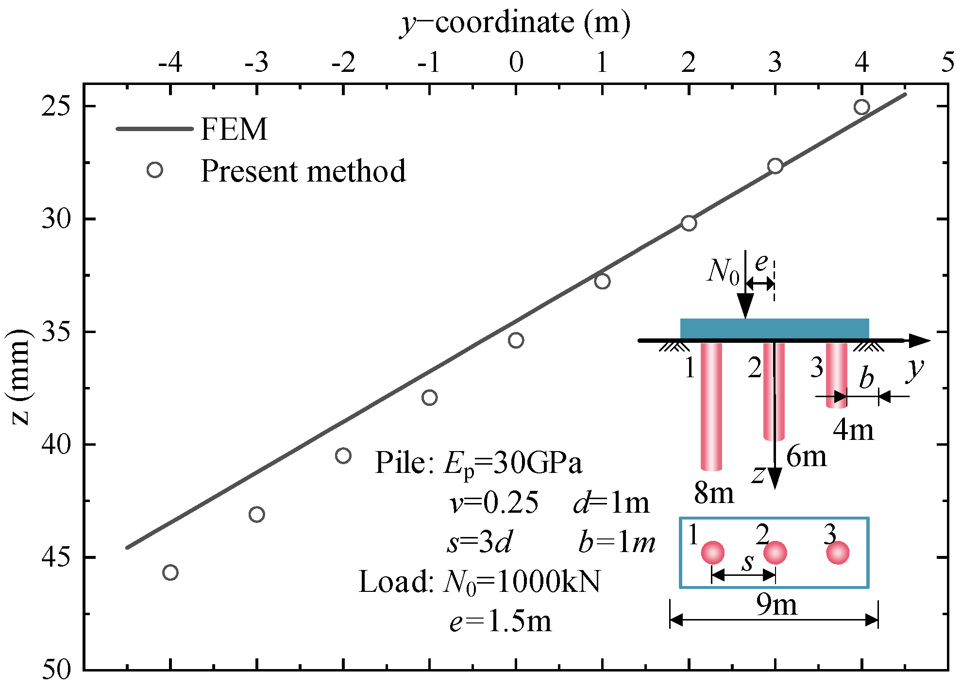
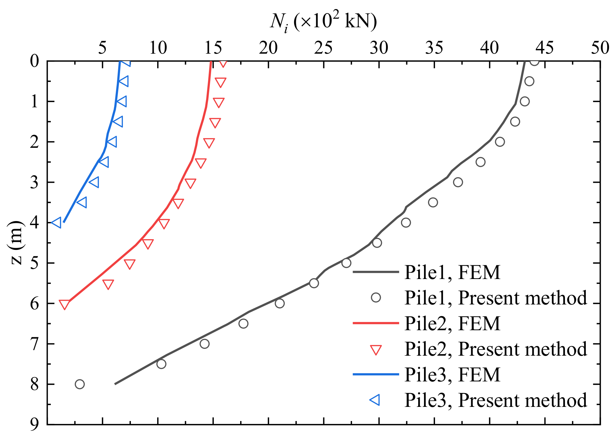
3.1. Validation Based on the Theoretical Method

In order to verify the accuracy of the present method, comparison with reported cases is needed. W.Y. Shen [28] reported the solutions for a 3 × 3 PRF under vertical load in homogeneous soil based on a variational method. Those solutions are obtained by the present method and compared, as shown in Figure 4 and Figure 5. Figure 4 also illustrates the PRF configurations and load condition. Good agreement in the non-dimensional vertical stiffness 2N0/Gdw and the load sharing ratio of the raft and piles Ni/N0 with different l/d can be observed between the two different methods, where N0 and w are the vertical load and raft settlement, respectively, G is the soil shear modulus, Ep/G = 3000, v is taken to be 0.499, and the raft overhang b = d.

3.2. Validation Based on the Numerical Method

A FEM validation study based Plaxis 3D is also performed to ensure that the present method produces reliable and accurate results. The length, width and height of the model are 40 times the raft width, respectively. The bottom of the model is fixed in both horizontal and vertical directions. The four side boundaries are fixed only in the horizontal direction and free in the vertical direction. The elastic constitutive model is considered for soil elements, which is consistent with the theoretical model. The 3 × 1 PRF with dissimilar pile length rested on homogeneous soil with Es = 30 MPa and v = 0.25; the pile parameters and load condition are detailed in Figure 6. Figure 6 also shows a comparison of the raft settlement response obtained from the present method with the FEM. The axial force distribution along the depth of piles obtained from the present method and the FEM are plotted in Figure 7. The raft and piles responses from both two methods are quite close to each other.

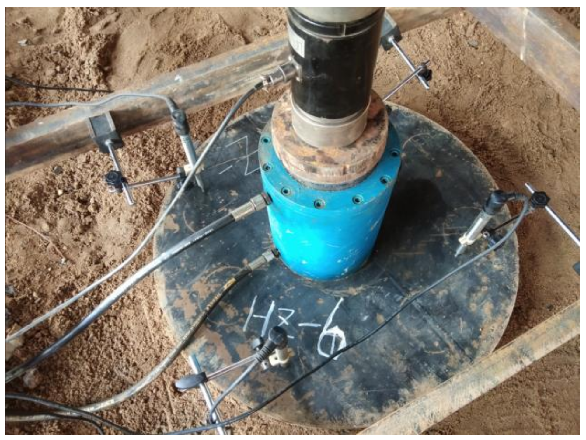
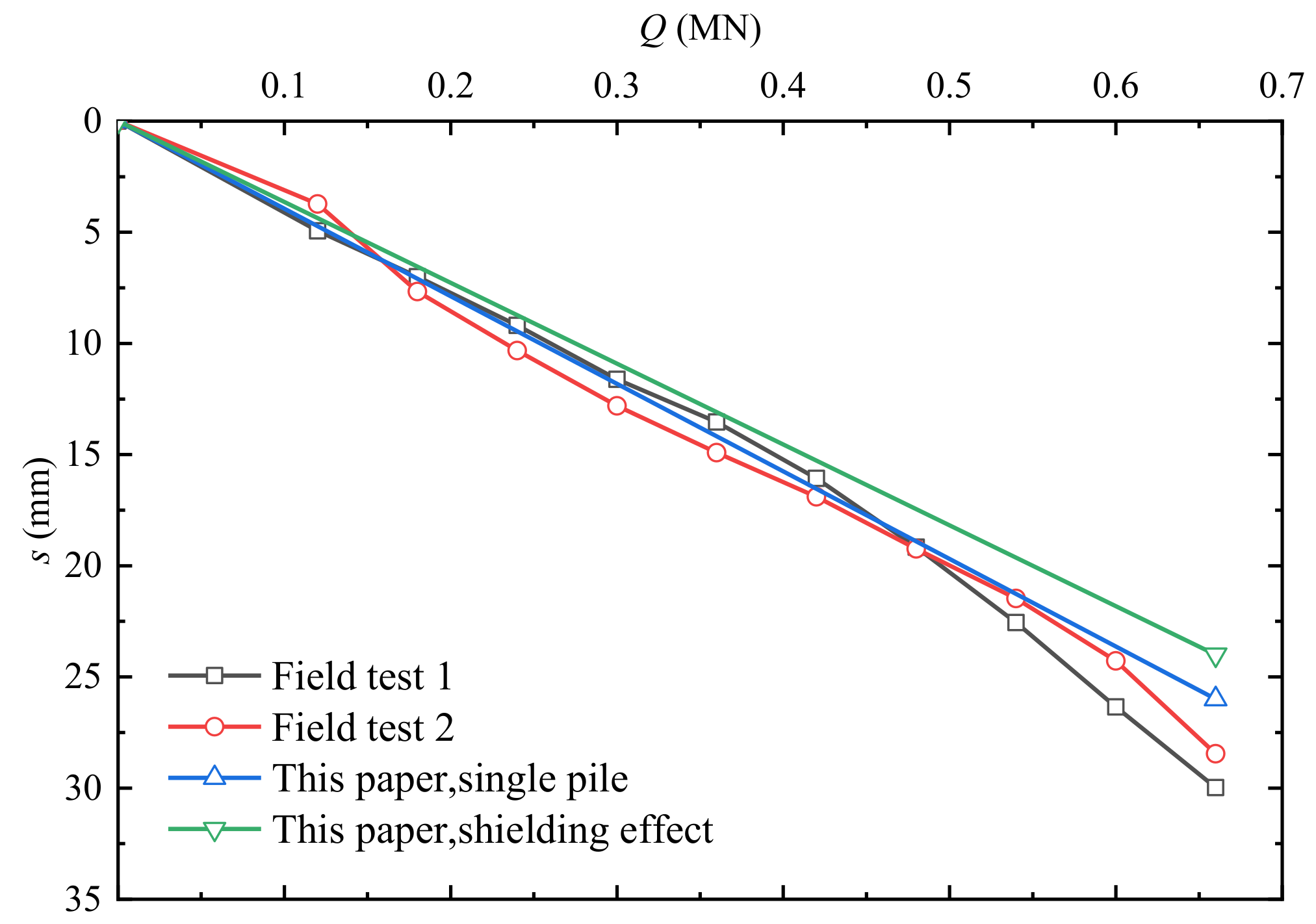
3.3. Validation Based on the Field Load Test

A shallow buried anchorage foundation was proposed in the Wujiagang Yangtze river bridge of Yichang city, where the underlying stratum is soil–rock composite ground. The diameter and embedded depth of foundation is 85 m and 15 m. As shown in Figure 8, the dissimilar micro-pile composite foundation is adopted to adjust the vertical and horizontal stiffness of the bearing stratum. The micro-piles are arranged in the shape of quincunx. And the diameter, pile space and length of the loaded pile are 0.3 m, 2.0 m and 7.0 m, respectively, and the elastic modulus of the pile and bearing stratum are supposed as 50 MPa and 30 GPa; the Poisson ratio is set as 0.25 for the pile and bearing stratum.
The two field load tests for a single micro-pile are investigated, and the testing process is shown in Figure 9.
The Q-s curves of the two load tests and theoretical solutions are presented in Figure 10 and are similar at the initial stage. With the loading increases, a difference in the Q-s curves between the two methods can be observed as the plastic settlement emerges. Comparing the theoretical solutions indicates that the enforcement and shielding effect of neighborhood piles can have limited improvements in the pile stiffness due to the large pile spacing.

4. Case Study

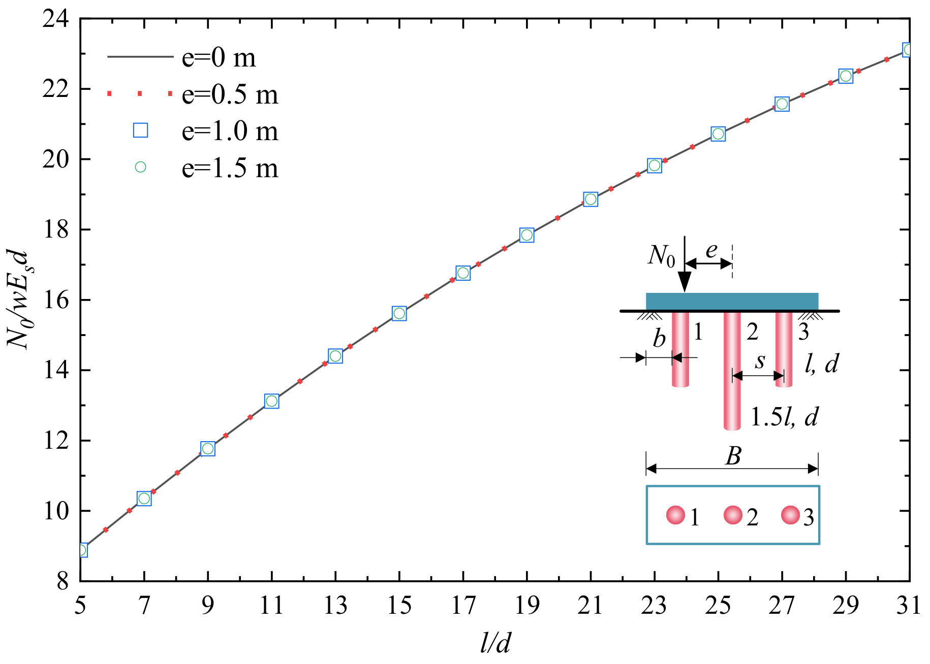
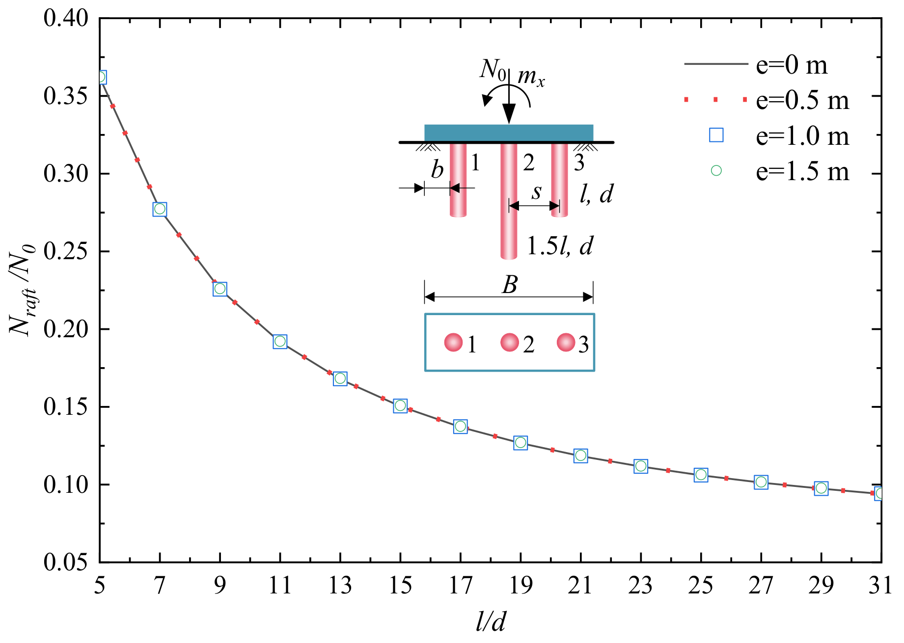
4.1. 3 × 1 PRF with Dissimilar Pile Length

A 3 × 1 PRF with dissimilar pile length under eccentric load is first proposed, as shown in Figure 11. The Es and v of soil are taken to be 30 MPa and 0.25, respectively, and Ep = 30 GPa, d = b = 1 m, v = 0.25 and s = 3 d for the pile parameters. The results are presented for the non-eccentric load (e = 0 m) and compared to the eccentric load with different eccentricity e (e = 0.5 m, 1.0 m, 1.5 m). The length to diameter ratio of the side piles (pile 1 and pile 3) is set as l/d, and keeping the pile length ratio between the middle pile (pile 2) and side pile is 1.5.
Figure 11 and Figure 12 display the effects of l/d on the non-dimensional vertical stiffness N0/wEsd and load sharing ratios of the raft Nraft/N0 for different eccentricity e. The results show that the N0/wEsd increased with l/d and the Nraft/N0 decreased with l/d, and furthermore, the different eccentricity e ranging from 0 m to 1.5 m, as is the case in the present analysis, has a small influence on the parameters N0/waEsd and Nraft/N0. A smaller increase in Nraft/N0 is to be expected due to the larger vertical stiffness of the piles with the l/d increase.
Then, the effects of the eccentric vertical load on the differential settlement wd and the load sharing ratio of side piles Ni/N (i = 1, 3) are addressed. Note that the raft rotation is consistent with the negative moment mx, which means that the negative moment mx results in a negative differential settlement wd of the rigid raft base on the coordinate system of Figure 1.
The wd and the Ni/N (i = 1, 3), as expected, are significantly affected by the eccentricity e, as shown in Figure 13 and Figure 14. For the differential settlement wd, the increase in eccentricity e causes a significant increase in wd, regardless of l/d, and the influence degree of eccentricity e is more significant for shorter piles, becoming less significant for longer piles for all of the conditions. Relative to the eccentricity e = 0.5 m condition, the increase in the differential settlement wd is about 100% and 200% for e = 1.0 m and 1.5 m, respectively, for the range of l/d. The predicted e-wd response trend using the proposed method compares well with [29].
As the vertical stiffness of the piles increases with l/d and the differential settlement wd increases with eccentricity e, the load sharing ratio of pile 1 increases with eccentricity e and l/d, and the load sharing ratio of pile 3 increases with l/d and decreases with eccentricity e. Compared with the non-eccentric condition, the load sharing ratio of pile 1 increases by about 23%, 47% and 70% for e = 0.5 m, 1.0 m and 1.5 m when l/d = 5, respectively, and the corresponding figures for l/d = 31 are 25%, 50% and 74%.
Figure 15 and Figure 16 provide insights into the load sharing ratio of each element for l/d = 5 and 15. It is noted that the load sharing ratio of the corner elements is greater than the side elements, and the side elements are larger than the center elements due to the pile–soil–cap interactions under the center load (e = 0 m), which agrees well with the published results from Liang and Song [20] and Randolph and Wroth [30]. For the PRF under eccentrical load, the load sharing ratio changes with eccentricity e obviously, and the load sharing ratios for elements 9, 18 and 27 are about 0 as the eccentricity e = 1.5 m = B/6. For l/d = 5, the load sharing ratio of pile 1 (element 11) is about 0.19 for the center load and increases to 0.37 for eccentricity e = 1.5 m. For l/d = 15, the load sharing ratio of pile 1 is 0.25 and 0.49, respectively.

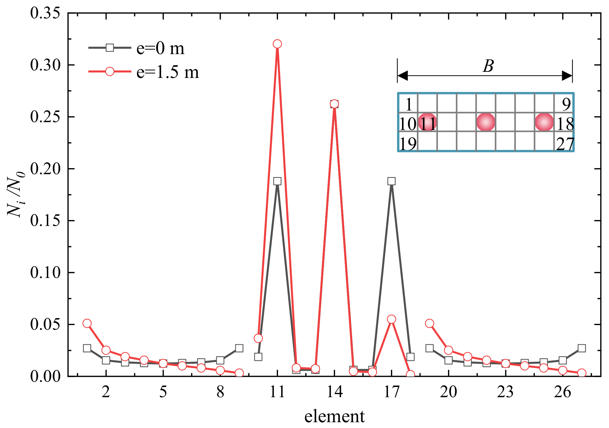
4.2. 3 × 3 PRF with Dissimilar Pile Length

The behavior of a 3 × 3 dissimilar PRF with different pile rigidity is also explored. In engineering applications, when the pile–soil modulus ratio, Ep/Es, is up to 3000 or 20, the pile is often considered as a rigid pile and flexible pile, respectively. Figure 17 and Figure 18 display the non-dimensional vertical stiffness N0/wEsd and the load sharing ratio of the raft Nraft/N0 against the l/d, respectively. For the flexible pile condition, only small differences in the N0/wEsd curve and Nraft/N0 curve are recognized for different l/d, the N0/wEsd of the system is maintained at about 11.8, and the raft transmits about 0.72 of the applied load N0 directly to the soil. For the rigid pile condition, the linear increase in N0/wEsd with l/d from 15.7 to 25.8 can be found obviously, and the reduction in Nraft/N0 with l/d from 0.26 to 0.12 is recognized, respectively. Therefore, pile rigidity has a significant effect on N0/wEsd and Nraft/N0.
The variation of the differential settlement wd for a PRF with different l/d and pile rigidity is similar with non-dimensional vertical stiffness N0/wEsd, as shown in Figure 19. The load sharing ratio of element 11 N11/N0 in the 3 × 3 PRF with different pile rigidity and eccentricity e are shown in Figure 20. The load sharing ratio of the flexible pile condition are correspondingly smaller than the rigid pile condition.
To provide insights into the load sharing ratios of typical elements under eccentric vertical load, the load sharing ratios of element 37 to element 45 for different pile rigidity are compared in Figure 21 and Figure 22. The pile rigidity has a significant influence on the load sharing ratio for all l/d. The load sharing ratio of the edge pile (element 38), center pile (element 41) and edge pile (element 44) with l/d = 5 is 0.181, 0.143 and 0.017 for the rigid pile, and 0.046, 0.02 and 0.01 for the flexible pile. The corresponding ratios for l/d = 15 are 0.172, 0.10 and 0.02, and 0.05, 0.02 and 0.01.
The effects of pile–soil modulus ratios Ep/Es on N0/wEsd, wd and N38/N0 with different eccentricity e are analyzed in detail, as shown in Figure 23, Figure 24 and Figure 25. These Ep/Es cover the range normally used in practice. As can be expected, the non-dimensional stiffness of a PRF, N0/wEsd, as the load is carried by the pile, should be increased with the Ep/Es, and the differential settlement wd should be decreased with the Ep/Es. The N0/wEsdEp/Es curves are identical for different eccentricity e. For each eccentricity e, N0/wEsd is about 13.64 when Ep/Es = 20, increasing to 18.81 when Ep/Es = 500, and increasing slowly to 19.30 when Ep/Es = 2000.
Figure 24 shows that the increase in Ep/Es causes a significant reduction in wd regardless of the eccentricity e, and less pronounced variation for wd is observed when Ep/Es larger than 200. Furthermore, the greater the eccentricity e, the larger the wd is performed due to the greater interaction among the pile–soil–raft.
Similar to the wd-Ep/Es curves in Figure 24, the load sharing ratio of N38/N0 significantly increases with Ep/Es up to Ep/Es = 500, and the N38/N0 is almost unchanged when Ep/Es > 500 for different eccentricity e, which is shown in Figure 25.

5. Conclusions

The bearing characteristic of dissimilar PRFs under eccentric vertical load is a key issue in engineering applications. Two dissimilar PRFs under eccentric vertical load are studied based on the boundary element method. Following the proposed analytical model, governing equations and an iterative algorithm for n−pile PRF, the effect of critical design parameters (e, l/d, Ep/Es) on the behavior (N0/wEsd, wd, Ni/N0) of PRFs is investigated. This paper can capture the pile–soil–raft interaction more reasonably, and is validated with the theoretical results and the FEM. The following conclusions can be drawn from this work.
(1)
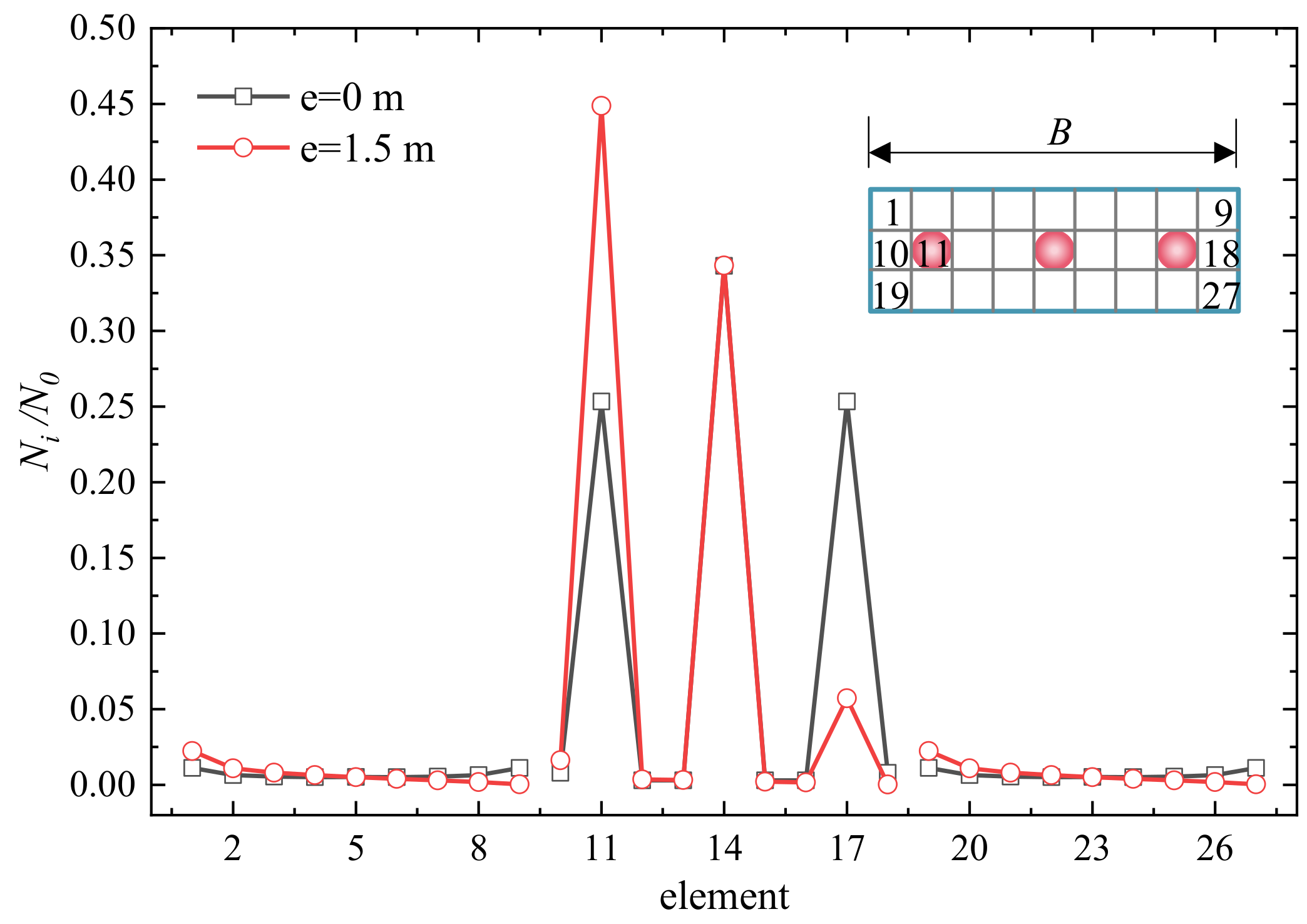
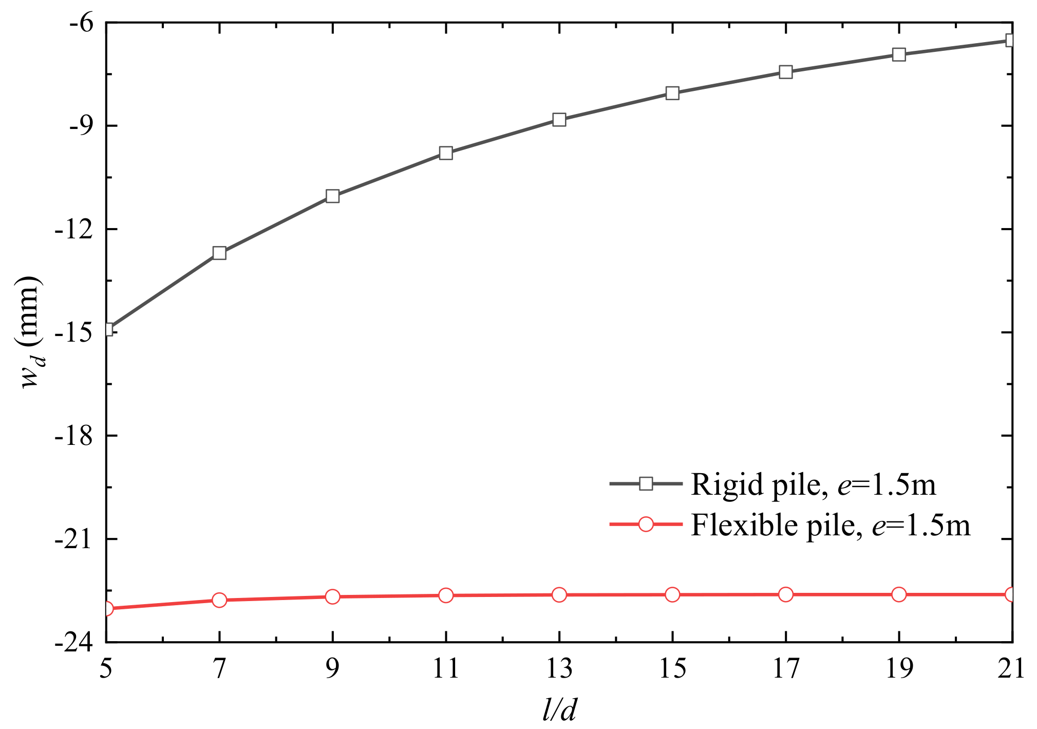
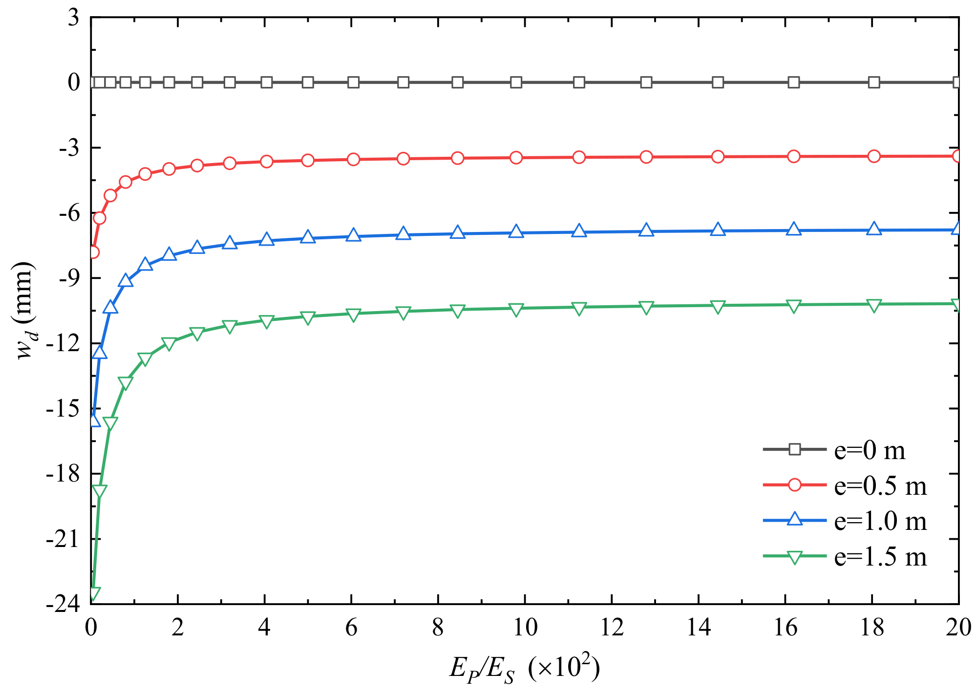
For a 3 × 1 PRF, the non-dimensional vertical stiffness N0/wEsd increased with l/d; the load sharing ratios of the raft Nraft/N0 and the differential settlement wd decreased with l/d. The eccentricity e has a significant effect on the differential settlement wd and the load sharing ratio of each element and has a neglect effect on N0/wEsd and Nraft/N0.
(2)
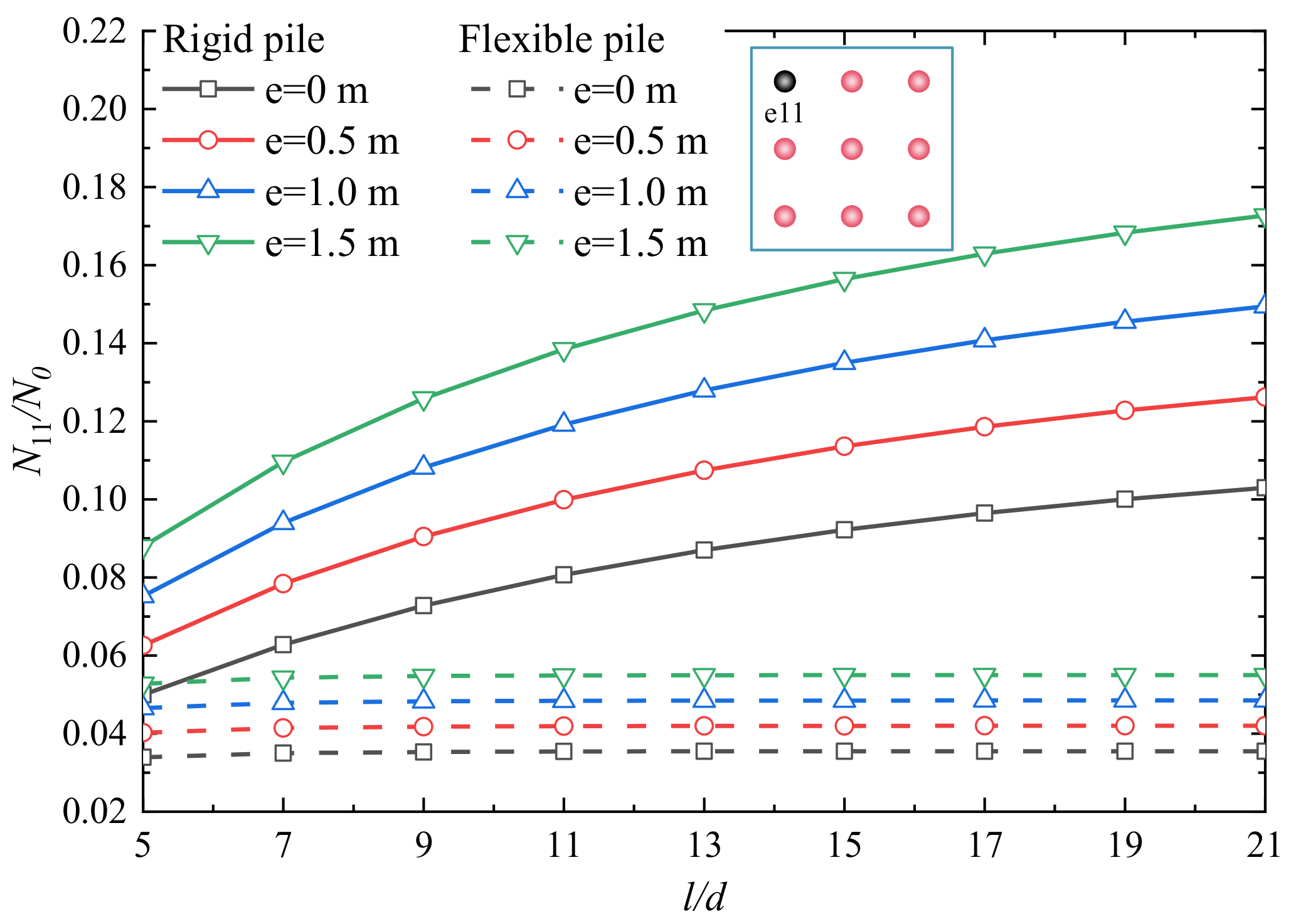
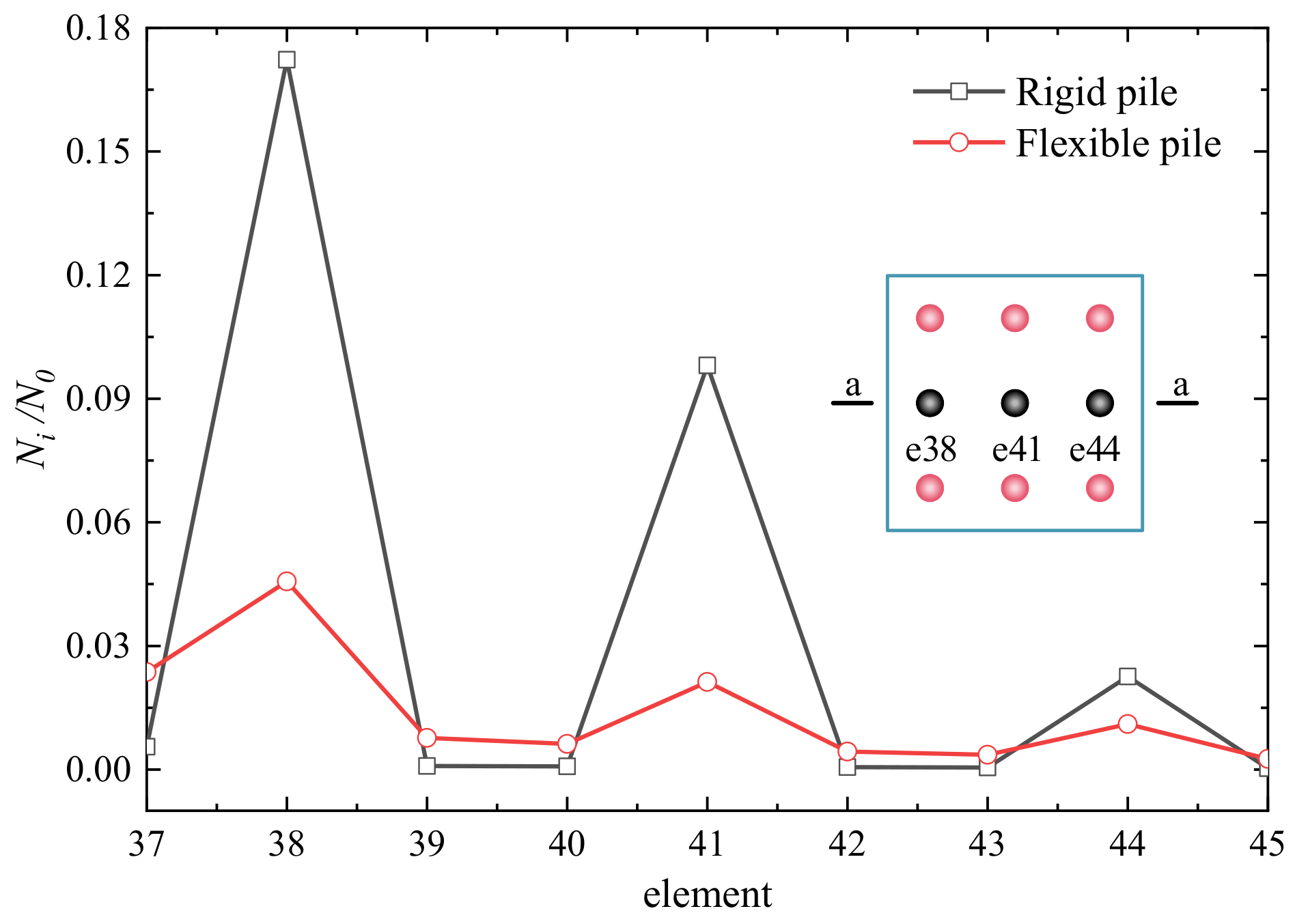
For a 3 × 3 PRF, the pile rigidity and l/d have a significant effect on N0/wEsd, Nraft/N0, wd and the load sharing ratio of each element. And the load sharing ratio of each element, Ni/N0 and wd are significantly influenced by eccentricity e.
(3)
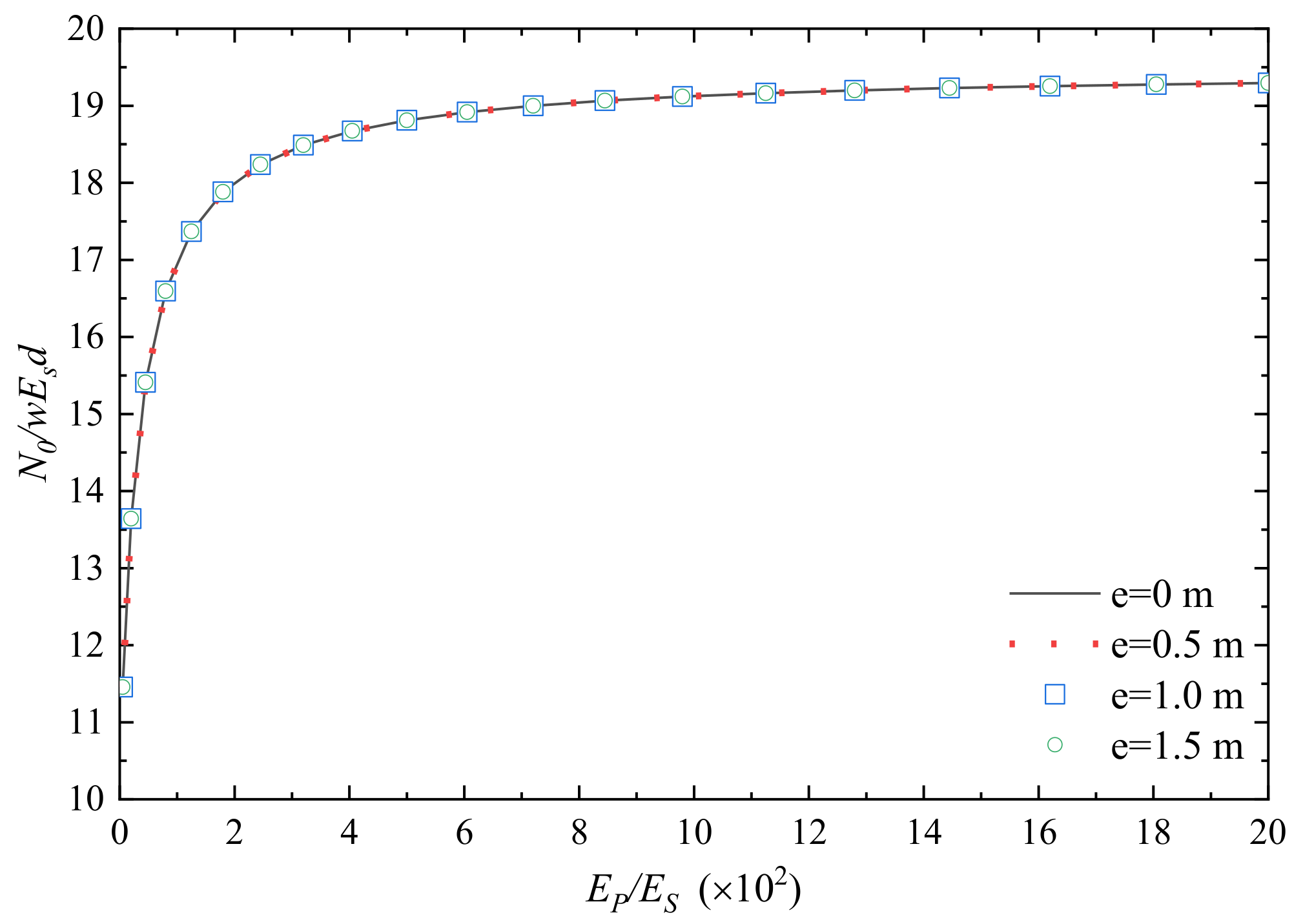
For a 3 × 3 PRF, N0/wEsd, wd and N38/N0 are significantly increased with Ep/Es. The eccentricity e has an obvious effect on wd and N38/N0 for different Ep/Es, but it does not change N0/wEsd significantly.

Author Contributions

Methodology, software and validation, K.H.; writing—original draft preparation and supervision, K.J. and X.G.; project administration, W.W. and T.Z.; numerical simulation and filed tests, L.Y.; investigation, Z.G. and G.C. All authors have read and agreed to the published version of the manuscript.

Funding

This project was supported by the General Program of China Postdoctoral Science Foundation (2023MD734111), sponsored by the Natural Science Foundation of Chongqing, China (CSTB2023NSCO—MSX0853, CSTB2023NSCO—MSX0433, CSTC2021JCYJ—MSXMX0343), and the Scientific and Technological Research Program of Chongqing Municipal Education Commission (KJQN202101236, KJZD—K202301205, KJQN—202301260).

Data Availability Statement

The data used to support the findings of this study are available from the corresponding author upon request. The data are not publicly available due to privacy.

Conflicts of Interest

The authors declare no conflict of interest.

References

  1. Poulos, H.G. Tall building foundations: Design methods and applications. Innov. Infrastruct. Solut. 2016, 1, 10. [Google Scholar] [CrossRef]
  2. De Sanctis, L.; Di Laora, R.; Maiorano, R.M.S.; Favata, G.; Aversa, S. Failure envelopes of pile groups under combined axial-moment loading: Theoretical background and experimental evidence. Soils Found. 2021, 61, 1419–1430. [Google Scholar] [CrossRef]
  3. Song, J.; Yang, Y.; Jia, K.; Dou, P.; Ma, X.; Shen, H. Seismic response and instability analysis of the liquefiable soil-piles-superstructure interaction system. Structures 2023, 54, 134–152. [Google Scholar] [CrossRef]
  4. Andrea, F.; Brian, S. Pile groups under vertical and inclined eccentric loads: Elastoplastic modelling for performance based design. Comput. Geotech. 2021, 135, 104092. [Google Scholar] [CrossRef]
  5. Dai, G.; Salgado, R.; Gong, W.; Zhang, Y. Load tests on full-scale bored pile groups. Can. Geotech. J. 2012, 49, 1293–1308. [Google Scholar] [CrossRef]
  6. Zhang, Q.; Zhang, Z.; Yu, F.; Liu, J. Field performance of long bored piles within piled rafts. Proc. Inst. Civ. Eng. Geotech. Eng. 2010, 163, 293–305. [Google Scholar] [CrossRef]
  7. De Sanctis, L.; Di Laora, R.; Garala, T.K.; Madabhushi, S.P.G.; Viggiani, G.M.B.; Fargnoli, P. Centrifuge modelling of the behaviour of pile groups under vertical eccentric load. Soils Found. 2021, 61, 465–479. [Google Scholar] [CrossRef]
  8. Mandal, S.; Sengupta, S. Experimental Investigation of Eccentrically Loaded Piled Raft Resting on Soft Cohesive Soil. Indian Geotech. J. 2017, 47, 314–325. [Google Scholar] [CrossRef]
  9. Park, D.; Lee, J. Interaction effects on load-carrying behavior of piled rafts embedded in clay from centrifuge tests. Can. Geotech. J. 2015, 52, 1550–1561. [Google Scholar] [CrossRef]
  10. Mylonakis, G. Contributions to Static and Seismic Analysis of Piles and Pile-Supported Bridge Piers; State University of New York: New York, NY, USA, 1996. [Google Scholar]
  11. Shen, W.; Chow, K.; Yong, K.-Y. A variational approach for vertical deformation analysis of pile group. Int. J. Numer. Anal. Methods Geomech. 1997, 21, 741–752. [Google Scholar] [CrossRef]
  12. Di Laora, R.; de Sanctis, L.; Aversa, S. Bearing capacity of pile groups under vertical eccentric load. Acta Geotech. 2018, 14, 193–205. [Google Scholar] [CrossRef]
  13. Roy, J.; Kumar, A.; Choudhury, D. Pseudostatic Approach to Analyze Combined Pile-Raft Foundation. Int. J. Geomech. 2020, 20, 06020028. [Google Scholar] [CrossRef]
  14. Meyerhof, G.G. The bearing capacity of rigid piles and pile groups under inclined loads in clay. Can. Geotech. J. 1981, 18, 297–300. [Google Scholar] [CrossRef]
  15. Meyerhof, G.G.; Yalcin, A.S.; Mathur, S.K. Ultimate Pile Capacity for Eccentric Inclined Load. J. Geotech. Eng. 1983, 109, 408–423. [Google Scholar] [CrossRef]
  16. Chow, Y.K.; Teh, C.I. Pile-Cap-Pile-Group Interaction in Nonhomogeneous Soil. J. Geotech. Eng. 1991, 117, 1655–1668. [Google Scholar] [CrossRef]
  17. Fayun, L.; Zhu, S.; Guo, W.D. Group interaction on vertically loaded piles in saturated poroelastic soil. Comput. Geotech. 2014, 56, 1–10. [Google Scholar] [CrossRef]
  18. Bhaduri, A.; Choudhury, D. Serviceability-Based Finite-Element Approach on Analyzing Combined Pile–Raft Foundation. Int. J. Geomech. 2020, 20, 04018103. [Google Scholar] [CrossRef]
  19. Bhartiya, P.; Basu, D.; Chakraborty, T. Effect of Design Parameters on Piled Rafts in Sand under Eccentric Triangular Loads. Int. J. Geomech. 2022, 22, 04022060. [Google Scholar] [CrossRef]
  20. Liang, F.Y.; Song, Z. BEM analysis of the interaction factor for vertically loaded dissimilar piles in saturated poroelastic soil. Comput. Geotech. 2014, 62, 223–231. [Google Scholar] [CrossRef]
  21. Liang, F.Y.; Chen, L.Z.; Han, J. Integral equation method for analysis of piled rafts with dissimilar piles under vertical loading. Comput. Geotech. 2009, 36, 419–426. [Google Scholar] [CrossRef]
  22. Sheil, B.B.; McCabe, B.A. A finite element–based approach for predictions of rigid pile group stiffness efficiency in clays. Acta Geotech. 2013, 9, 469–484. [Google Scholar] [CrossRef]
  23. Shatnawi, A.; Almasabha, G.; Tarawneh, B. Structural Behavior of Concrete Box Culverts under Deep Burial. J. Pipeline Syst. Eng. Pract. 2017, 8, 04017025. [Google Scholar] [CrossRef]
  24. Almasabha, G.; Shehadeh, A.; Alshboul, O.; Al Hattamleh, O. Structural performance of buried reinforced concrete pipelines under deep embankment soil. Constr. Innov. 2023. ahead-of-print. [Google Scholar] [CrossRef]
  25. Muki, R.; Sternberg, E. Elastostatic Load-Transfer to a Half-Space from a Partially Embedded Axially Loaded Rod. Int. J. Solids Struct. 1970, 6, 69–90. [Google Scholar] [CrossRef]
  26. Mindlin, R.D. Force at a Point in the Interior of a Semi-Infinite Solid. Physics 1936, 7, 195–202. [Google Scholar] [CrossRef]
  27. Muki, R.; Sternberg, E. On the diffusion of load from an infinite cylindrical bar embedded in an elastic medium. Int. J. Solids Struct. 1969, 5, 587–605. [Google Scholar] [CrossRef]
  28. Shen, W.Y.; Chow, Y.K.; Yong, K.Y. A variational approach for the analysis of pile group–pile cap interaction. Geotechnique 2000, 50, 349–357. [Google Scholar] [CrossRef]
  29. Padmavathi, M.; Padmavathi, V.; Madhav, M.R. Response of two-pile group subjected to vertical eccentric load. Int. J. Geotech. Eng. 2020, 14, 626–635. [Google Scholar] [CrossRef]
  30. Randolph, M.F.; Wroth, C.P. An analysis of the vertical deformation of pile groups. Geotechnique 1979, 29, 423–439. [Google Scholar] [CrossRef]
Figure 1. Map of dissimilar PRF and the discretized square sub-elements.
Buildings 13 03040 g001
Figure 2. Decomposition system and force analysis of the dissimilar PRF.
Buildings 13 03040 g002
Figure 3. Solving algorithm based on an iterative process.
Buildings 13 03040 g003
Figure 4. The relationship between 2N0/Gdw and l/d [28].
Buildings 13 03040 g004
Figure 5. Load sharing ratios of piles and raft (s/d = 5) [28].
Buildings 13 03040 g005
Figure 6. The settlement distribution of raft foundation.
Buildings 13 03040 g006
Figure 7. The axial force distribution of piles.
Buildings 13 03040 g007
Figure 8. Field excavation of the shallow buried anchorage foundation.
Buildings 13 03040 g008
Figure 9. Field load test of a single pile.
Buildings 13 03040 g009
Figure 10. Q-s curves of the tests and theoretical method.
Buildings 13 03040 g010
Figure 11. The relationship between N0/wEsd and l/d.
Buildings 13 03040 g011
Figure 12. The relationship between Nraft/N0 and l/d.
Buildings 13 03040 g012
Figure 13. The relationship between wd and l/d for different e conditions.
Buildings 13 03040 g013
Figure 14. The relationship between Ni/N and l/d for different e conditions.
Buildings 13 03040 g014
Figure 15. Load sharing ratio of each element (l/d = 5).
Buildings 13 03040 g015
Figure 16. Load sharing ratio of each element (l/d = 15).
Buildings 13 03040 g016
Figure 17. The relationship between N0/wEsd and l/d.
Buildings 13 03040 g017
Figure 18. The relationship between Nraft/N0 and l/d.
Buildings 13 03040 g018
Figure 19. The relationship between wd and l/d.
Buildings 13 03040 g019
Figure 20. The relationship between N11/N0 and l/d.
Buildings 13 03040 g020
Figure 21. Load sharing ratio of each element (l/d = 5, e = 1.5 m).
Buildings 13 03040 g021
Figure 22. Load sharing ratio of each element (l/d = 15, e = 1.5 m).
Buildings 13 03040 g022
Figure 23. Effect of Ep/Es on N0/wEsd for different e conditions.
Buildings 13 03040 g023
Figure 24. Effect of Ep/Es on wd for different e conditions.
Buildings 13 03040 g024
Figure 25. Effect of Ep/Es on N38/N0 for different e conditions.
Buildings 13 03040 g025
Disclaimer/Publisher’s Note: The statements, opinions and data contained in all publications are solely those of the individual author(s) and contributor(s) and not of MDPI and/or the editor(s). MDPI and/or the editor(s) disclaim responsibility for any injury to people or property resulting from any ideas, methods, instructions or products referred to in the content.

