Article

Experimental Study on Flexural Performance of Recycled Steel Fiber Concrete Beams

1
School of Architecture and Civil Engineering, Xihua University, Jinzhou Road 999#, Chengdu 610039, China
2
State Key Laboratory of Geohazard Prevention and Geoenvironment Protection, No. 1, East Third Road, Erxianqiao, Chengdu 610059, China
*
Author to whom correspondence should be addressed.
Buildings 2023, 13(12), 3046; https://doi.org/10.3390/buildings13123046
Submission received: 14 October 2023 / Revised: 26 November 2023 / Accepted: 29 November 2023 / Published: 7 December 2023
(This article belongs to the Special Issue Structural Dynamic Disaster and Protection)

Abstract

:
We sorted the waste from mechanical processing to form recycled steel fibers. In order to study the flexural mechanical properties of reinforced concrete beams after the addition of recycled steel fibers, four recycled steel fiber concrete beams (RSFCBs) and one normal concrete beam (NCB) were designed and poured using the volume fraction of steel fibers (0%, 0.5%, 1%, 1.5%, 2%) as the variables. Normal section bending tests were conducted on them under a concentrated load. We obtained experimental data such as the cracking load, ultimate load, mid-span deflection, and steel and concrete strain of the beam by gradually loading the test beam, and we observed and recorded the development of cracks. The results indicate that the NCB exhibits crushing failure, while the RSFCBs exhibit equilibrium failure. The addition of recycled steel fibers effectively controls the extension of cracks, resulting in a better bending toughness of the beam. The bending performance of RSFCBs with different volume additions shows a trend of first increasing and then decreasing with the increase in steel fiber content. The peak value was reached when the steel fiber content was 1.5%, which increased the bending bearing capacity by 54.72% compared with the NCB. With the increase in steel fiber content, the required load value for tensile steel bars to yield also increases, reaching a peak at a content of 1.5%, which increases the bending bearing capacity by 44.64% compared with the NCB. The addition of recycled steel fibers enables the beam to improve its bearing capacity while limiting the development of longitudinal reinforcement strain, allowing the longitudinal reinforcement to yield under higher loads and improving the overall bending performance of the beam.

1. Introduction

The greenization of civil engineering materials is one of the ways to achieve the global goal of reducing carbon emissions. According to the data, the building sector is responsible for nearly 40% of global carbon emissions, and as the world’s major emitter, China faces enormous pressure to cut carbon emissions [1,2]. Due to China’s recent growth in infrastructure investment and its growing economy, the construction industry has emerged as a significant source of carbon emissions. Large amounts of greenhouse gases will be released during the manufacturing of building materials, seriously harming the environment. To lessen carbon dioxide emissions and environmental strain, the building sector has switched its development focus to cement-based composite materials created from solid waste [3,4,5,6]. One of these is recycled steel fiber (RSF).
Because the presence of waste iron filings in the environment has a serious impact on the sustainable development of the environment, people have recently begun to pay special attention to the disposal of waste iron filings. According to statistics, the rapid expansion of mechanical processing results in enormous amounts of waste iron filings. These waste iron filings will substantially hurt the public environment, cause pollution, and require recycling to meet our nation’s goal of sustainable development [7,8,9]. The residual material from mechanical processing forms recycled steel fibers in a spiral shape, which are randomly distributed in the concrete and form a three-dimensional spatial structure with the concrete, effectively preventing the development of concrete cracks and enhancing the tensile and toughness properties of the concrete. If recycled steel fibers are added to concrete instead of original steel fibers to form recycled steel fiber concrete material, it not only solves the problem of easy cracking of concrete and improves the mechanical properties of concrete, but also effectively solves the treatment difficulties of recycled steel fibers, achieving the green goal of civil material production [10,11,12,13].
Concrete is a brittle substance with a high compressive strength but low tensile strength. Reinforced concrete (RC) is a material that is suited for civil engineering construction by overcoming the weakness of concrete’s low tensile strength. Adding random scattered RSFs to RC structures is a good way to improve their mechanical qualities. RSFs usually exist in a spiral form, forming a solid three-dimensional skeleton in concrete with good mechanical properties. Recycled steel fiber-reinforced concrete (RSFRC) is a heterogeneous composite made up of cement, fine and coarse aggregate, and RSF that has been placed randomly, among other materials. The addition of RSF in the random distribution can effectively prevent the growth of microcracks in concrete and postpone the occurrence and development of macrocracks. It can also increase the tensile, shear, and flexural strength of concrete, lessen its brittleness, and improve RSFRC’s ductility, impact toughness, and permeability resistance compared with regular concrete. RSFRC also exhibits less creep and shrinkage than regular concrete [14,15,16,17,18]. With an increase in RSF content, the more fiber-mixed layers within a specified proportion range, the better the impermeability and flexural performance of concrete [19,20,21,22,23,24,25]. These findings suggest that RSFRC is crucial to the advancement of materials for civil engineering.
Steel fiber-reinforced concrete research is continuously developing. Yoo et al. studied the mechanical properties of ten ultra-high-performance concrete beams by changing the ratio of reinforcement and the type of steel fibers. The test results showed that the addition of steel fibers significantly improved the bearing capacity, post-cracking stiffness, and cracking response, but reduced the ductility [26]. Through a three-point notched beam bending test, Zamanzadeh et al. assessed the viability of using RSF as shear reinforcement in reinforced concrete beams [27]. RSFRC and steel bars’ bonding characteristics have been examined by Leone et al., and the results have been contrasted with those of industrial steel fiber-reinforced concrete. The results show that most of the performance of ISFRC can reach that of RSFRC [28]. Through experiments with three-point loads, Arslan et al. investigated the effect of steel fiber dosage on the shear performance of reinforced concrete beams with webs. The results showed that the test beams’ bearing capacity and ductility were improved by using steel fiber, but the limited influence effect persisted [29]. Golpasand et al. used uniaxial cyclic compression and biaxial tests to investigate the performance of RSFRC. The results indicated that RSF could perform almost as well as industrial steel fiber, suggesting that RSF might be utilized in concrete in place of that material [30]. Through a four-point bending test, Domski et al. investigated the enhancing impact of steel fiber on waste sand concrete beams. The findings indicated that the inclusion of steel fiber increased the concrete’s tensile strength and compressive strength [31]. Through trials, Revuelta et al. compared the performance of tire RSF with that of industrial steel fiber or polypropylene fiber. The findings revealed that, when added to the concrete at the same amount as native fiber, RSF had the same effect [32]. Simalti et al. investigated how recycled steel fibers (RSFs) from used tires affected the physical properties of self-compacting concrete, and the results demonstrated that RSFs can increase self-compacting concrete’s durability [33]. These studies collectively demonstrate that the addition of steel fiber to concrete can increase the mechanical strength and toughness of reinforced concrete structures, demonstrating the potential of RSFRC as a modern structural material.
On the basis of existing research, spiral-shaped recycled steel fibers are formed by sorting the leftover materials from mechanical processing, and these steel fibers are added to concrete for the first time to form recycled steel fiber-reinforced concrete composite materials. Through preliminary experimental research on the basic mechanical properties of recycled steel fibers, it was found that the strength of recycled steel fiber-reinforced concrete was slightly improved compared with ordinary concrete, but the tensile strength and toughness performance of recycled steel fiber-reinforced concrete was significantly increased. In order to further study the mechanical properties of recycled steel fibers in concrete flexural members, four recycled steel fiber-reinforced concrete beams and one ordinary concrete beam were created, and their flexural bearing capacity under a concentrated load was tested to explore feasible paths for the application of recycled steel fiber-reinforced concrete in engineering practice.

2. Test Overview

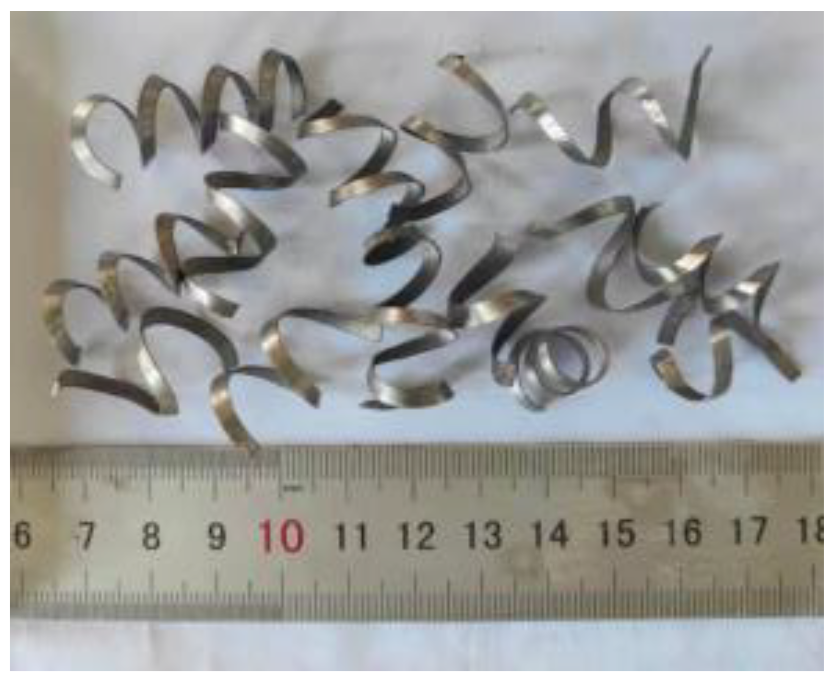
2.1. Test Material and Mix Ratio

The test concrete is composed of various components, such as river sand, fly ash, stone, water, steel bars, cement, etc. The composition of the concrete mixture is changed by adding a high-efficiency water-reducing agent and recycled steel fiber [34,35,36].
The cement used regular silicate cement P.O 42.5, which complies with General Silicate Cement GB175-2007 standards [37]. The gravel used as the coarse aggregate had a particle size range of 5 to 20 mm. The specific parameters are listed in Table 1, and all indexes comply with GB/T14685-2011 Pebble and Gravel for Construction specifications [38]. The river sand was a fine aggregate, and it had a fineness modulus of 3.0 and a packing density of 1531 kg/m3. Fly ash was created by Tianjin Lejin Botian Chemical Co., Ltd. (Tianjin, China); it had an 800 mesh particle size. High-performance water reduction agent powder produced by Tianjin Weihe Science and Technology Development Co, Ltd. (Tianjin, China) was used in dosages of 0.3% to 0.5% when mixed with cement or rubber materials. The water used for blending was ordinary tap water. The waste product from machining is where the scrap steel fiber is found [39,40,41,42]. Its length was around 30 mm after treatment, and its density was 7850 kg/m3; the tensile strength of the recycled steel fibers obtained through unidirectional tensile testing was not less than 380 MPa, and their elastic moduli were 2.05 × 10⁵ MPa. The shape of the RSFs is shown in Figure 1.
The concrete used in the sample was of strength grade C30, with a cement, water, sand, and stone mix ratio of 1:0.46:1.69:3.29; the quantity of material is provided in Table 2.

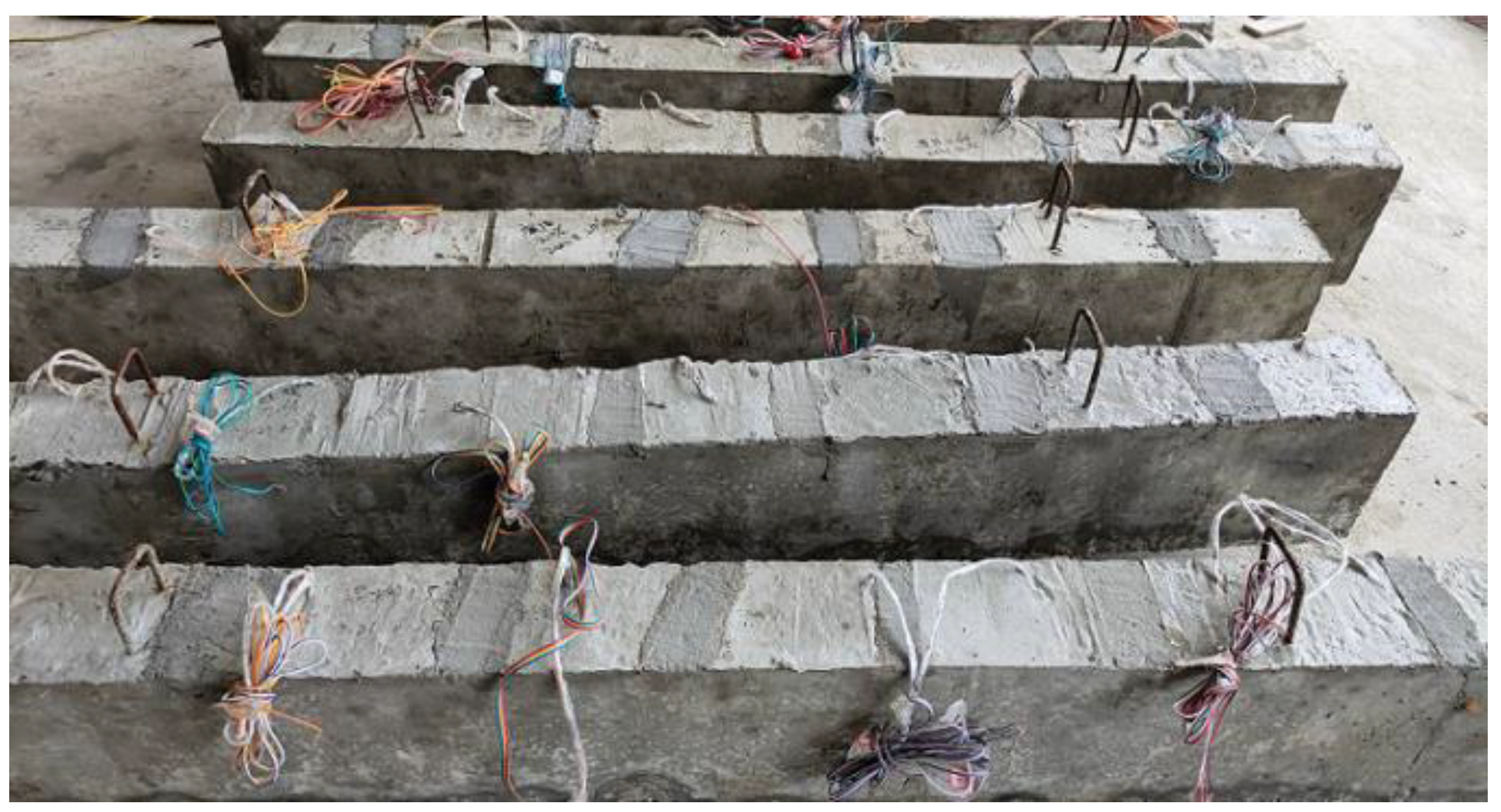
2.2. Preparation of Test Beams

Four recycled steel fiber-reinforced concrete beams and one ordinary reinforced concrete beam were designed according to the standard for the test method of concrete structures (GBT50152-2012) [43], and bending bearing capacity tests were conducted. Five simply supported beams with a target strength of C30 were constructed and cast for this experiment. Letters and numbers, separated by semicolons, were used to identify the test beams. The number denotes the volume content of recycled steel fibers, which ranges from 0% to 0.5%, 1%, 1.5%, and 2%, respectively. The letters indicate the type of steel fiber reinforced (NC for ordinary concrete and RSFRC for recycled steel fiber-reinforced concrete).
The test beam has a 2000 mm span, a 150 mm section width, and a 250 mm height. For details on the parameters, see Table 3. The lengths of the simply supported beam’s tensioned longitudinal and auxiliary steel bars are 1950 mm, and the thickness of the concrete protection layer is 15 mm. In the region of flexural shear, HPB335 stirrups with a diameter of 4 mm and a spacing of 100 mm were inserted to protect the specimen from shear damage. The longitudinal bar used for tensile purposes has an 8 mm diameter and is ribbed HRB400 steel. The test beams’ reinforcing ratio is 0.44%. Figure 2 displays the sectional size and beam reinforcement diagram. The concrete strength grade of all beams was C30.
Using an already-made test template, the concrete was artificially mixed and injected. After pouring, let it sit for 24 h on a flat surface before demolding it. Due to conservation conditions, the finished component was watered to ensure that the surface was always moist, with a humidity of above 90% and an outdoor temperature of 20 ± 3 °C, and the curing process took 28 days [44,45,46,47,48,49], as shown in Figure 3. After curing, a test of the mechanical properties was performed.
In Table 3, NCB means ordinary reinforced concrete beams, RSFCB—0.5% refers to a recycled steel fiber-reinforced concrete beam with a volume content of 0.5% recycled steel fibers, and so on.

2.3. Test Loading and Measurement

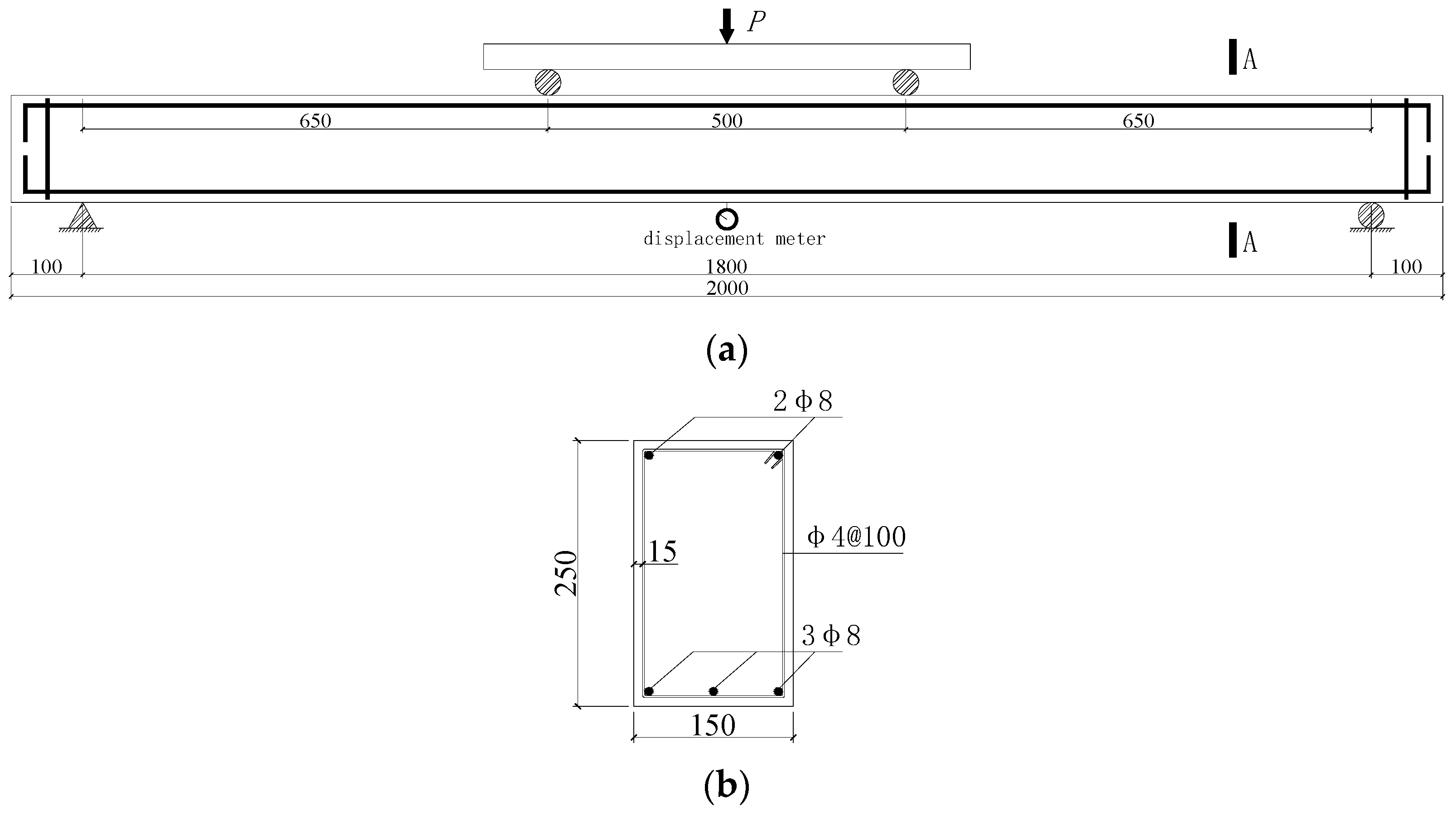
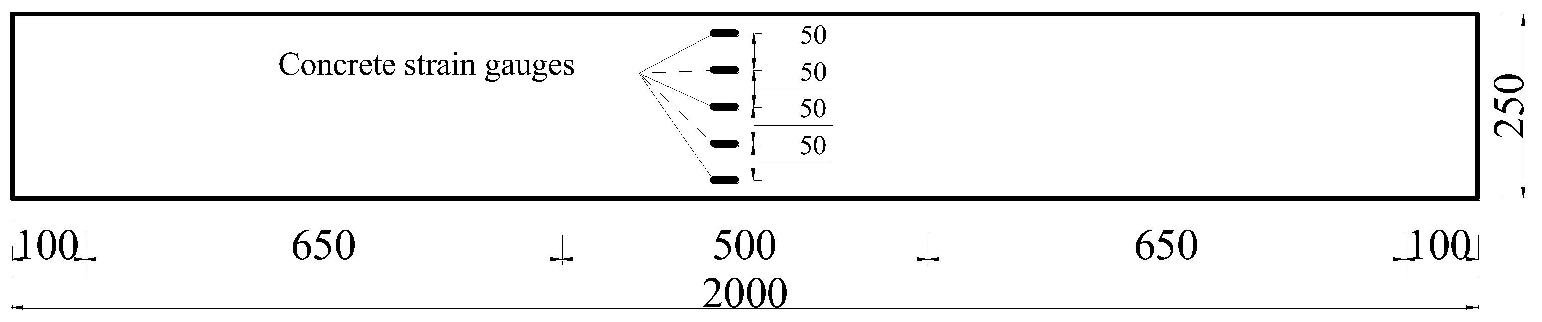
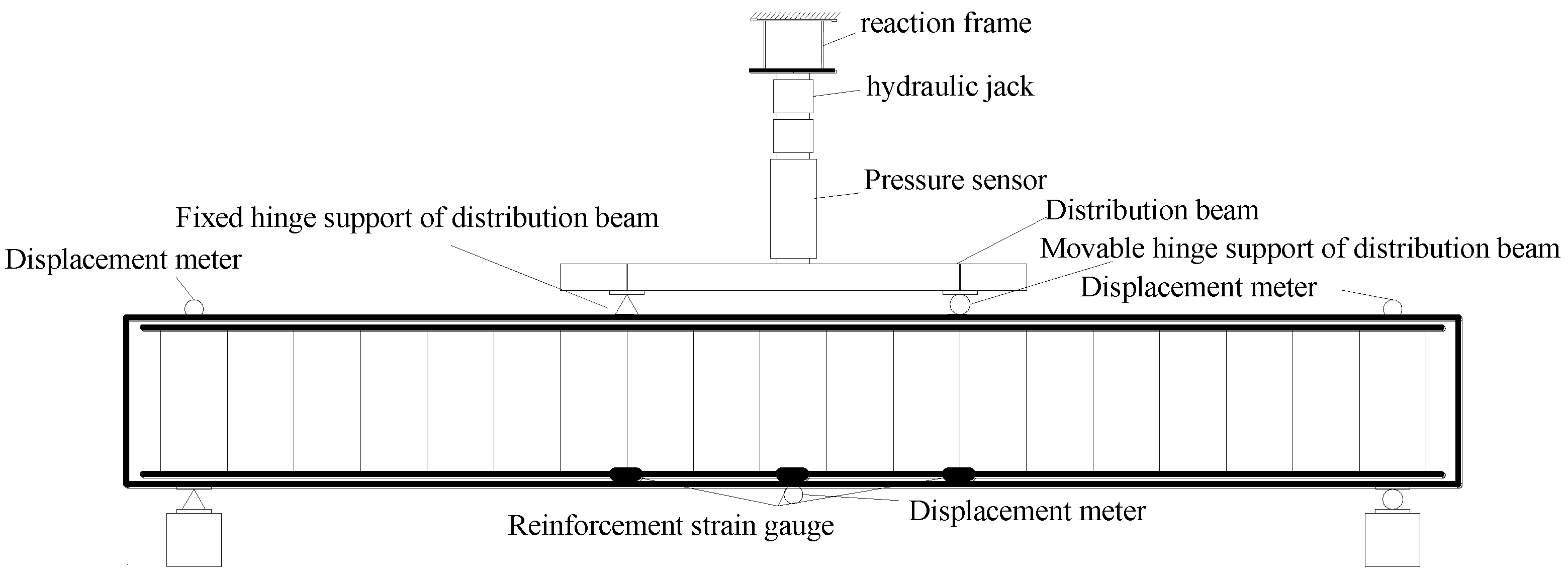
2.3.1. Loading Device and Measurement Point Arrangement

The strain, crack width, applied load, and mid-span deflection of reinforced concrete in the test beam are the primary parameters that were measured in this study.
This test device uses the distribution beam’s loading device to perform the four-point bending test [50,51,52]. One end of the test beam is supported by hinges, and the other end is supported by rollers. The test span is 1800 mm, the distance between the two concentrated forces is 500 mm, the support is 100 mm from the test beam’s end, and the load is distributed through the distribution beam.
The strain gauge used was a BX120-5aa (Beijing Yiyang Strain Testing Technology Co., Ltd., Beijing, China) strain gauge, and the placement of the reinforcement strain gauge corresponds to the placement of the reinforcement at the mid-span and loading point. As indicated in Figure 4, the concrete strain gauge is affixed to the concrete surface in the middle span of one test beam side.
In the test, three strain-type displacement sensors with a range of 100 mm and accuracy of 0.01 mm were installed to detect the deflection at the middle and end supports of the beam, respectively.
On the test beam’s surface, use a marker pen to draw a square grid with sides of 50 mm, then use a magnifying glass and crack width contrast card to track the crack’s progress. As soon as the test beam’s bearing capacity is steady and the crack has stopped extending following the completion of the load loading, mark the current load value at the end and trace and number the crack along the direction it has extended. Record the actual crack number, distribution, width, and related load value on the grid paper. The segment between the two loading sites is pure bending if the dead weight of the beam is disregarded. The loading device is shown in Figure 5 and Figure 6.

2.3.2. Loading System

Before the formal loading, pre-loading is performed to ensure there is proper contact between the test beam and the test device and that the measurement equipment can operate normally [53,54]. The preloading load is separated into three levels and has an ultimate load that is 70% of the test beam’s expected cracking load. The load is discharged to zero after making sure that there is good contact between the test beam and the test object and that the measuring tools function as intended.
Step loading has been adopted for the formal loading phase. The loading level was 2 kN before the first crack developed, and once the crack appeared, the load was increased to 5 kN per level. The test beam was stable for three minutes after each level of loading, at which point data were gathered. When the test beam’s bearing capacity is almost at its maximum load, the loading mode is switched from load control to control through the beam’s midspan displacement using a loading gradient of 1 mm until the test beam is destroyed. To avoid damage, the displacement meter should be taken out when the mid-span displacement is too great.

3. Experimental Phenomena and Analysis

To assess the effect of the volume fraction of recycled steel fiber on the flexural performance of reinforced concrete beams, the test process and failure modes of five test beams were examined. To evaluate the flexural performance of WSFRC, test beams were loaded with various RSF volume fractions, and the cracking load, ultimate load, and maximum mid-span deflection were then analyzed.

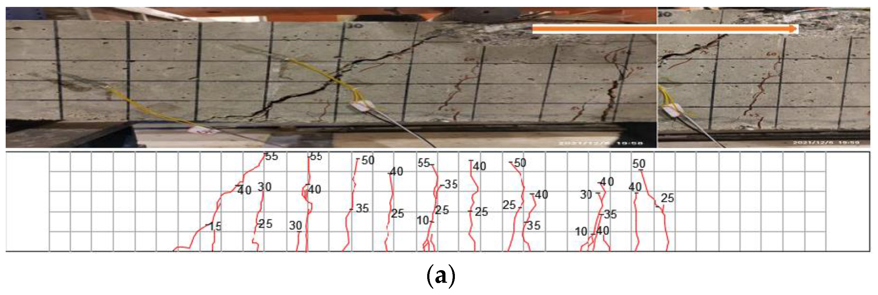
3.1. Test Phenomenon

The failure mechanism of an RSFRC beam when bent is comparable with that of an ordinary reinforced concrete beam and can be classified into three categories: insufficient reinforcement failure, over-reinforcement failure, and proper reinforcement failure [55,56,57,58]. The destruction of this test beam belongs to the proper reinforcement destruction. All of the test beams demonstrated equilibrium failure in addition to the ordinary reinforced concrete beams, with RSFRC—1.5% being the most glaring example. Now, each test beam’s failure mechanism is explained.
The failure mode of each beam is depicted in Figure 7. During the test, the crushing failure of ordinary reinforced concrete beams was seen. There was balance failure in the steel fiber-reinforced concrete beams. This balance failure indicates that the longitudinal tensile reinforcement has reached yield, the concrete in the compression zone has reached its limiting compressive stress and has been crushed, the specimen is in the elastic deformation stage just before cracking, and the concrete and longitudinal tensile reinforcement are jointly stressed.

3.1.1. NCB

When the load on the plain reinforced concrete beam comparison specimen NCB reached 5 kN, the first vertical crack began to appear in the purely bending section nearby the loading point; as the load increased, more cracks began to appear in the test beam, one after the other. The primary crack near the loading point reached 0.8 mm in width when the load hit 30 kN. The entire specimen reached a stable state when the load reached 45 kN. There were no evident new cracks in the beam’s pure bending region, and the crack’s greatest width was roughly 3 mm when the tensile longitudinal reinforcement yielded. The concrete near the top of the beam’s pure bending portion exhibited a localized uplift phenomenon when the final load hit 55 kN. The member was still stable as the bearing capacity reached its limit at this point. Change the load control to displacement control and keep applying the load to the beam at the 1 mm/time loading frequency. The member has now hit the limit condition because, even though the load value of the beam appears to have slightly increased, it is no longer able to sustain the load steadily for an extended period, and the load always drops to 55 kN. The loading ceases when the mid-span deflection reaches 30.1 mm; the load falls to 45 kN, and the entire specimen is damaged. The failure pattern is shown in Figure 7a.

3.1.2. RSFCB—0.5%

The RSFCB—0.5% test beam steel fiber volume doping is relatively small. Its cracking load was 6 kN, its crack width was around 0.04 mm, and its initial crack was found on the right side beneath the loading point. When cracks appeared in large numbers, the load was between 35 and 55 kN. Five major vertical cracks started to appear in the pure bending section of the beam, and all of them extended to about 3/5 of the beam height. At this point, the span deflection was 4.86 mm. When the load was raised to 60 kN, the test beam entered its limit state. As the load was applied, the already-existing crack grew wider, and when the mid-span deflection reached 32.8 mm, the beam failed and created a crisp sound. When the load was abruptly reduced to 50 kN, the test beam’s deformation was obvious. The failure pattern is shown in Figure 7b.

3.1.3. RSFCB—1%

The test beam of RSFRC—1% had a cracking load of 8 kN, a crack width of about 0.03 mm, a mid-span deflection of 0.82 mm, and an initial crack located in the mid-span. When the load was increased to 35 kN, cracks started to substantially increase and spread to half of the height of the beam. At this time, there were five major fractures with large widths. When the load reached 50 kN, no new cracks are created, and those that already existed gradually extended to the top of the beam. At this point, the primary cracks in the mid-span reached about 4/5 of the height of the beam, and the height of the test beam pressure zone was decreased. The beam reached its ultimate bearing capacity when the load hit 65 kN. The test beam was damaged and terminated when the mid-span deflection reached 31.9 mm. The failure pattern is shown in Figure 7c.

3.1.4. RSFCB—1.5%

The RSFRC—1.5% test beam had the highest ultimate and cracking loads out of the four beams that also contained recycled steel fiber. The crack situated in the middle of the beam’s span had a crack width of roughly 0.02 mm and a cracking load of 10 KN. When the load was increased to 55 kN, the pure bending and curved shear sections of the beam both experienced numerous cracks that stretched to half of the beam’s height. In the pure bending area, four major cracks appeared. When the load was increased to 70 kN, the appearance of cracks tended to be stable; only the existing cracks continued to spread, and no new cracks appeared. As the load on the test beam increased to 82 kN to reach the limit state, the main crack propagated throughout the entire beam section and widened. As the load was applied, the deflection of the beam increased, but the load never deviated from 82 kN. When the mid-span deflection reached 41.2 mm, the beam’s bearing capacity rapidly declined, failing the test beam. The failure pattern is shown in Figure 7d.

3.1.5. RSFCB—2.0%

The RSFRC—2.0% test beam had a failure mode that was similar to RSFRC—1.5%, a cracking load of 8 kN, an initial crack that originated in the middle of the beam, and a width of 0.03 mm. When the load was between 45 and 60 kN, cracks in the pure bending section were fully developed and spread throughout the pure bending section, and six main cracks were created. The beam reached the stable stage when the load reached 70 kN, and no new cracks developed. The beam reached its ultimate bearing capacity when the load reached 78 kN, and it stopped increasing the bearing capacity after that point. When loaded with displacement control until the mid-span deflection was 37.2 mm, the test beam failed, and the test was terminated when the beam’s bearing capacity declined and two major cracks ran through the whole section. The failure pattern was shown in Figure 7e.

3.2. Analysis of Test Results

The test beam’s normal section’s flexural failure is under-reinforced destruction, and it belongs to the ductile beam. The mid-span deflection data for this test were obtained using the strain displacement sensor, and the strain data were acquired using the Japanese TDS-303 data acquisition apparatus. All of the beams underwent the test, yielding the cracking load, ultimate load, crack bending moment, ultimate bending moment, and load–displacement curve. The results of these tests were then sorted, analyzed, and calculated.

3.2.1. Cracking Load and Ultimate Load

Table 4 and Figure 8 show that the steel fiber-reinforced concrete beams had higher ultimate and cracking loads than the ordinary concrete beam, which greatly increased the ultimate bearing capacity of the beams. The cracking load and ultimate bearing capacity of steel fiber are most noticeably increased at the 1.5% volume percentage. Comparing the RSFRC—1.5% beam to the NC-0 ordinary concrete beam, the cracking load and ultimate load of steel fiber are raised by 200% and 49.09%, respectively. The test beam’s ultimate bearing capacity increases after the addition of RSF and then drops. The ultimate bearing capacity rises as the steel fiber volume percentage rises from 0.5% to 1.5%, but it falls as the steel fiber volume percentage rises to 2.0%.

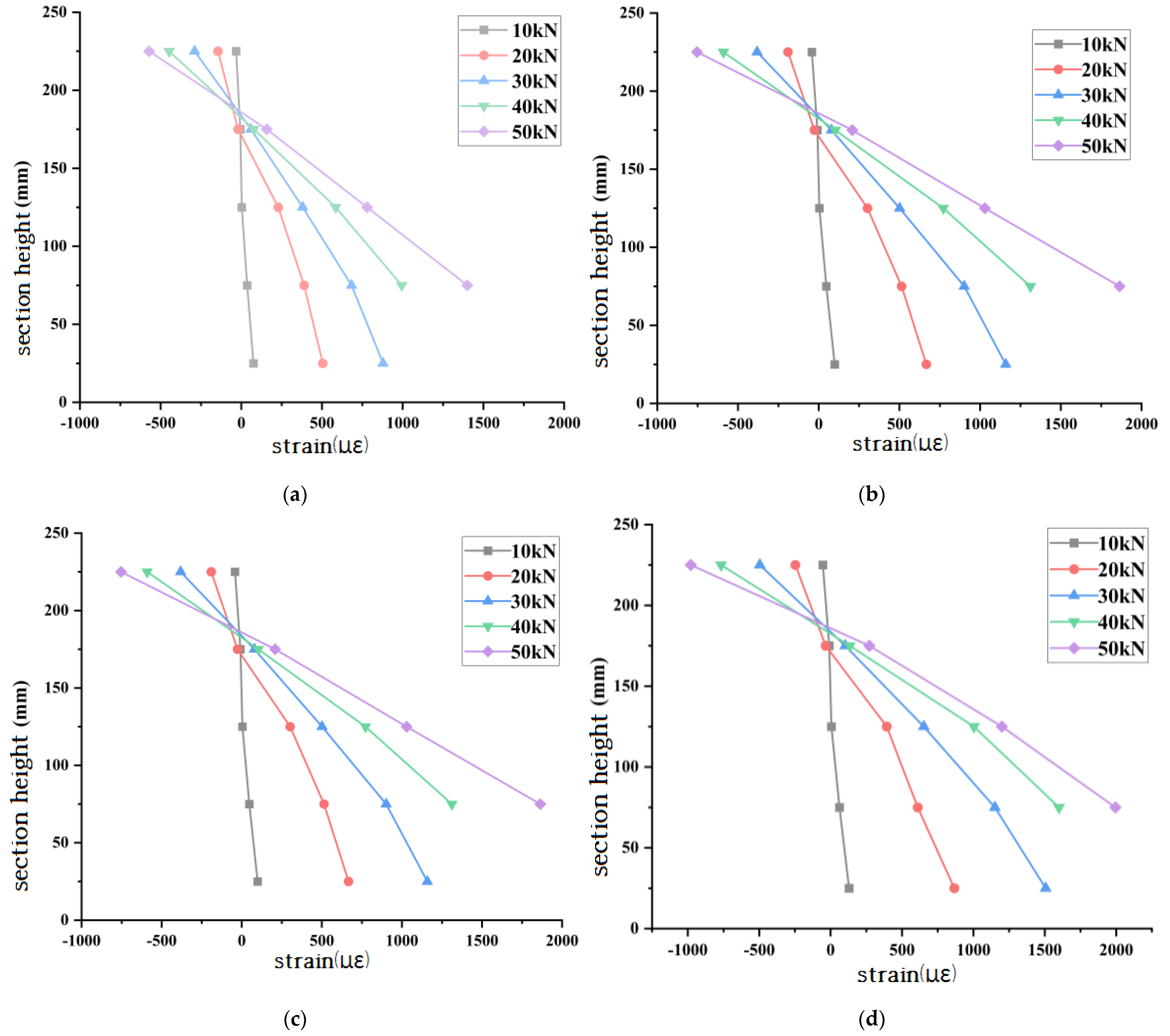
3.2.2. Plane Section Assumption

In order to investigate whether the pure bending section of the test beam remained planar throughout the test, the mid-span concrete strain of the recycled steel fiber concrete beam was analyzed. The average strain values of the test beams under loads of 10 kN, 20 kN, 30 kN, 40 kN, and 50 kN were analyzed. As shown in Figure 9, it can be observed that the concrete strain of the test beam develops almost linearly along the height of the section. It can be seen that when calculating the bending capacity of the normal section of the waste steel fiber-reinforced concrete beam, the concrete strain along the beam height conforms to the plane section assumption.

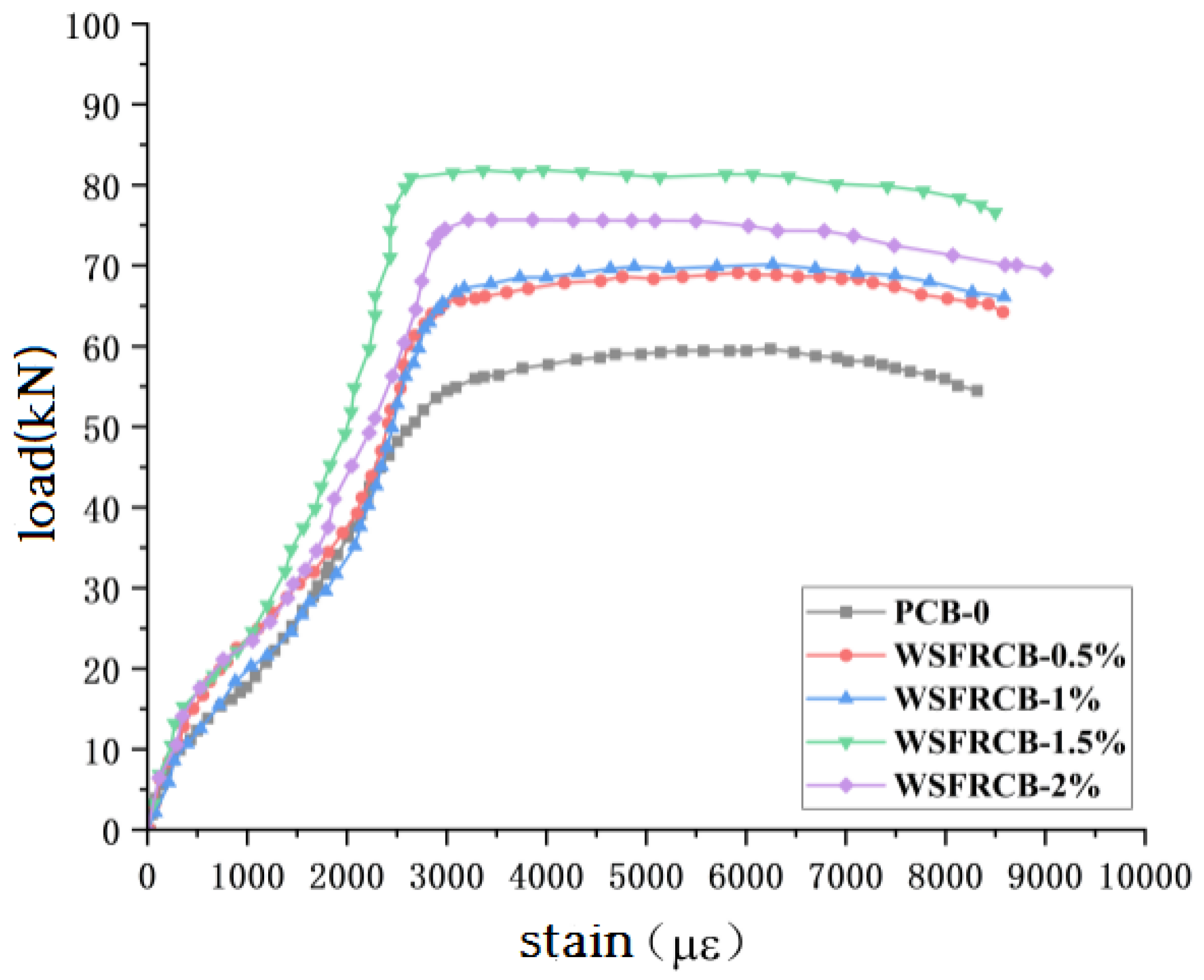
3.2.3. Load–Strain Analysis of Tensioned Longitudinal Reinforcement

The load–steel strain curve of each specimen is shown in Figure 10. This reflects the changing trend of longitudinal tensile steel strain during the entire process from loading to failure of the experimental beam. Under the action of load, the longitudinal tensile steel strain of the experimental beam can be roughly divided into two stages. The first stage is the elastic stage, where concrete cracks due to stress, causing the tensile stress at the crack to transfer to the steel fiber and tensile longitudinal reinforcement and where the strain of the longitudinal reinforcement begins to increase. As the load increases, there is a significant turning point in the load–strain curve of the longitudinal reinforcement, which is the yield point, and the reinforcement enters the yield stage.
In the early stage of loading, the longitudinal reinforcement strain of each component does not differ significantly and can be approxim ated as a linear increase, with a shorter duration; As the load increases, after cracks appear at the bottom of the mid-span beam, the strain of the longitudinal reinforcement rapidly increases and the slope of the curve decreases. Under the action of the same level of load, the longitudinal reinforcement strain value of the specimen NCB is the highest. The yield load value of tensile longitudinal reinforcement shows a trend of first increasing and then decreasing with the increase of steel fiber content, and reaches its peak when the steel fiber content is 1.5%. For the specimen NCB, when the load is loaded to 56 kN, the tensile longitudinal reinforcement reaches the yield point. For specimens RSFCB—0.5%, RSFCB—1%, RSFCB—1.5%, and RSFCB—2%, the tensile longitudinal reinforcement reaches the yield point when loaded to 65 kN, 67 kN, 81 kN, and 75 kN, respectively. Compared with the specimen NCB, the yield load of the tensile longitudinal reinforcement increased by approximately 16.07%, 19.64%, 44.64%, and 33.93%. This is because the addition of RSF delays the yield point of tensile steel bars, and can synergistically carry with tensile longitudinal bars, resulting in stronger bending deformation capacity and better ductility of reinforced concrete beams. It can improve bearing capacity while limiting the development of longitudinal bar strain, making longitudinal bars yield under higher loads, and improving the overall integrity of the beam.

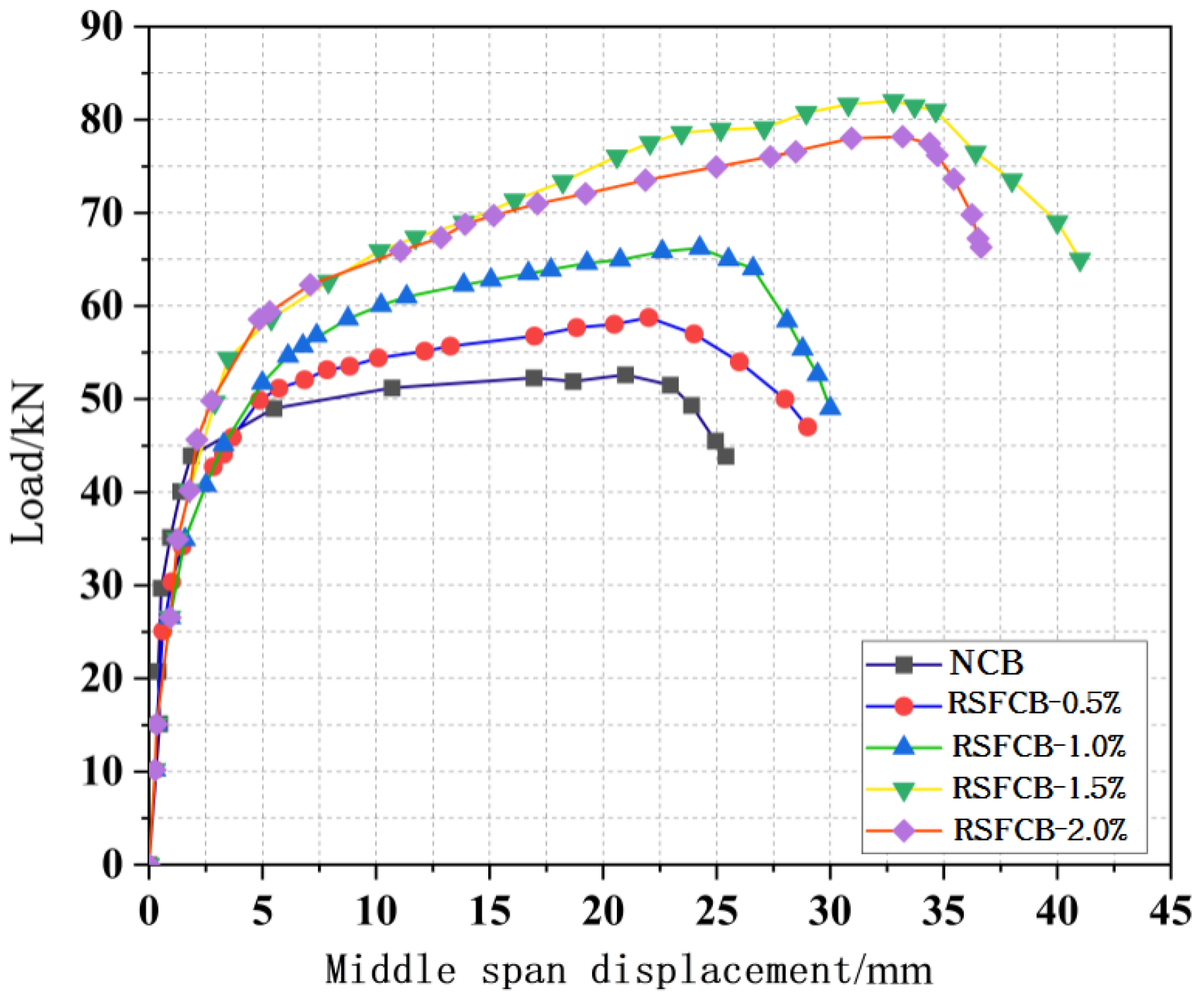
3.2.4. Load–Deflection Curve

Beams composed of steel fiber-reinforced concrete will flex downward when under load. A study was performed on the effect of steel fiber volume ratios of 0%, 0.5%, 1%, 1.5%, and 2% on test beam deflection. Before the test, a displacement meter was installed in the test beam’s two supports and spans to measure the displacement of the mid-span and support. The settlement error of the two supports should be eliminated when calculating the mid-span deflection [59,60,61].
The beam’s mid-span deflection is calculated using the formula shown below:
f = f m f l + f r 2
f is the mid-span deflection; fm is the measured value of mid-span displacement; fl is the measured displacement value of the left support; fr is the measured value of the right support.
The load–mid-span deflection curve of every test beam is depicted in Figure 11 to analyze the variation law of mid-span deflection under various steel fiber volume contents. As observed in the picture, there are three stages to the test beam’s mid-span deflection.
The first loading phase lasted from the start of the test until the load reached 45 kN. The mid-span deflection of the test beam grew slowly, growing linearly in this segment, and the mid-span deflection value was close. The reason why each test beam’s load–mid-span deflection curve roughly coincided in the 0–20 kN load range is because, early on in the load cycle, the tensile stress in the tensile zone is relatively low, the test beam is in the elastic stage, there is no obvious downward deflection trend, and the load–mid-span deflection curve is close to a straight line.
In the second stage, as the load continues to increase, the mid-span deflection of the test beam began to increase in a small amplitude, and the development of the mid-span deflection was faster than that of the first stage. In this stage, the crack of the test beam continued to increase, and the increase in the width led to the beam being unable to bear too much tensile stress, and the test beam gradually became plastic.
The third stage denotes the onset of the longitudinal reinforcement’s tensile yield strength up until the test beam’s failure. At this point, most of the steel fiber-reinforced concrete in the tension area had not been working, the tensile longitudinal reinforcement bore the majority of the tensile stress, and the test beam’s mid-span deflection value was quickly rising.
In general, RSFCB beams are more ductile and have a higher flexural capacity than regular concrete beams. With the increase in RSF volume rate, the mid-span deflection also increases, and the RSF volume fraction is 1.5% when the mid-span deflection value is maximum.

4. Conclusions

Five test beams with different RSF volumes were designed and poured. The bending performance of RSFCB beams was studied using a four-point loading test on distributed beams, and experimental data on the cracking load, ultimate load, mid-span deflection, concrete strain, and tensile steel strain were obtained. The research conclusions are as follows:
(1)
The NCB beam showed compressive failure, while the failure mode of the WSFRCBs were approximately the same with equilibrium failure. The RSFCB test beams all met the plane section assumption, and the steel bars reached yield during loading. When the yield point was reached, the yield strain of the steel bars was relatively close.
(2)
The cracking load and ultimate load of the WSFRCBs are higher than those of the NCB. The ultimate load generally shows a trend of increasing first and then decreasing with the increase in steel fiber content. When the steel fiber content is 1.5%, the ultimate load is the largest, which is 49.09% higher than that of the NCB. RSF can inhibit the development of cracks. The number of cracks increases with the increase in steel fibers, but the width decreases, achieving the effect of toughening, thereby effectively improving the ductility of the beam.
(3)
Reclaimed steel fibers can work together with concrete to improve the bearing capacity of reinforced concrete beams while limiting the development of longitudinal strains, allowing the longitudinal steel bars to yield under higher loads and improving the deformation capacity of reinforced concrete beams. The results also show that recycled steel fiber concrete has similar mechanical properties to ordinary steel fiber concrete, making it feasible for engineering practice.

Author Contributions

Conceptualization, Q.X.; methodology, Y.G.; software, W.Y.; validation, T.F.; formal analysis, J.Y.; investigation, J.Y.; resources, X.Z.; data curation, J.Y.; writing—original draft preparation, Y.G.; writing—review and editing, J.Y. All authors have read and agreed to the published version of the manuscript.

Funding

This research was funded by the National Science and Technology Support Program of China, the National Natural Science Foundation of China, and the State Key Laboratory of Geological Disaster Prevention and Geological Environmental Protection of Chengdu University of Technology, grant numbers 2015BAK09B01, 41877273, and SKLGP2019K019.

Data Availability Statement

Data will be made available upon request.

Acknowledgments

The author of the paper would like to thank the editors and reviewers for their guidance and feedback on the paper.

Conflicts of Interest

The authors declare that they have no known competing financial interest or personal relationships that could have appeared to influence the work reported in this paper.

References

  1. Wu, P.; Song, Y.; Zhu, J.; Chang, R.D. Analyzing the influence factors of the carbon emissions from China’s building and construction industry from 2000 to 2015. J. Clean. Prod. 2019, 221, 552–566. [Google Scholar] [CrossRef]
  2. Li, S.; Wu, Q.; Zheng, Y.; Sun, Q. Study on the Spatial Association and Influencing Factors of Carbon Emissions from the Chinese Construction Industry. Sustainability 2021, 13, 1728. [Google Scholar] [CrossRef]
  3. Toghroli, A.; Mehrabi, P.; Shariati, M.; Trung, N.T.; Jahandari, S.; Rasekh, H. Evaluating the use of recycled concrete aggregate and pozzolanic additives in fiber-reinforced pervious concrete with industrial and recycled fibers. Constr. Build. Mater. 2020, 252, 118997. [Google Scholar] [CrossRef]
  4. Gao, D.; Zhang, L.; Zhao, J.; You, P. Durability of steel fibre-reinforced recycled coarse aggregate concrete. Constr. Build. Mater. 2020, 232, 117119. [Google Scholar] [CrossRef]
  5. Zhong, H.; Chen, M.; Zhang, M. Effect of hybrid industrial and recycled steel fibres on static and dynamic mechanical properties of ultra-high performance concrete. Constr. Build. Mater. 2023, 370, 130691. [Google Scholar] [CrossRef]
  6. Zia, A.; Zhang, P.; Holly, I. Experimental investigation of raw steel fibers derived from waste tires for sustainable concrete. Constr. Build. Mater. 2023, 368, 130410. [Google Scholar] [CrossRef]
  7. Mastali, M.; Dalvand, A. Fresh and Hardened Properties of Self-Compacting Concrete Reinforced with Hybrid Recycled Steel–Polypropylene Fiber. J. Mater. Civ. Eng. 2017, 29, 04017012. [Google Scholar] [CrossRef]
  8. El-Sayed, T.A.; Shaheen, Y.B. Flexural performance of recycled wheat straw ash-based geopolymer RC beams and containing recycled steel fiber. Structures 2020, 28, 1713–1728. [Google Scholar] [CrossRef]
  9. Leone, M.; Centonze, G.; Colonna, D.; Micelli, F.; Aiello, M.A. Fiber-reinforced concrete with low content of recycled steel fiber: Shear behaviour. Constr. Build. Mater. 2018, 161, 141–155. [Google Scholar] [CrossRef]
  10. Peng, G.F.; Niu, X.J.; Long, Q.Q. Experimental Study of Strengthening and Toughening for Recycled Steel Fiber Reinforced Ultra-High Performance Concrete. Key Eng. Mater. 2014, 629, 104–111. [Google Scholar] [CrossRef]
  11. Mastali, M.; Dalvand, A.; Sattarifard, A.R.; Abdollahnejad, Z.; Illikainen, M. Characterization and optimization of hardened properties of self-consolidating concrete incorporating recycled steel, industrial steel, polypropylene and hybrid fibers. Compos. Part B Eng. 2018, 151, 186–200. [Google Scholar] [CrossRef]
  12. Siddika, A.; Al Mamun, M.A.; Alyousef, R.; Amran, Y.H.M. Strengthening of reinforced concrete beams by using fiber-reinforced polymer composites: A review. J. Build. Eng. 2019, 25, 100798. [Google Scholar] [CrossRef]
  13. Yang, J.; Peng, G.F.; Shui, G.S. Mechanical Properties and Anti-Spalling Behavior of Ultra-High Performance Concrete with Recycled and Industrial Steel Fibers. Materials 2019, 12, 783. [Google Scholar] [CrossRef] [PubMed]
  14. Neocleous, K.; Tlemat, H.; Pilakoutas, K. Design Issues for Concrete Reinforced with Steel Fibers, Including Fibers Recovered from Used Tires. J. Mater. Civ. Eng. 2006, 18, 677–685. [Google Scholar] [CrossRef]
  15. Teng, J.G.; Yu, T.; Fernando, D. Strengthening of steel structures with fiber-reinforced polymer composites. J. Constr. Steel Res. 2012, 78, 131–143. [Google Scholar] [CrossRef]
  16. Frazão, C.; Díaz, B.; Barros, J. An experimental study on the corrosion susceptibility of Recycled Steel Fiber Reinforced Concrete. Cem. Concr. Compos. 2018, 96, 138–153. [Google Scholar] [CrossRef]
  17. Frazão, C.M.V.; Barros, J.A.B.; Bogas, J.A. Durability of Recycled Steel Fiber Reinforced Concrete in Chloride Environment. Fibers 2019, 7, 111. [Google Scholar] [CrossRef]
  18. Liew, K.M.; Akbar, A. The recent progress of recycled steel fiber reinforced concrete. Constr. Build. Mater. 2020, 232, 117232. [Google Scholar] [CrossRef]
  19. Mansour, W.; Fayed, S. Flexural rigidity and ductility of RC beams reinforced with steel and recycled plastic fibers. Steel Compos. Struct. 2021, 41, 317–334. [Google Scholar] [CrossRef]
  20. Bichitra, S.N.; Kranti, J. Shear resistant mechanisms in steel fiber reinforced concrete beams: An analytical investigation. Structures 2022, 39, 607–619. [Google Scholar] [CrossRef]
  21. Cristina, F.; Joaquim, B.; Alexandre, B.J. Technical and environmental potentialities of recycled steel fiber reinforced concrete for structural applications. J. Build. Eng. 2022, 45, 103579. [Google Scholar] [CrossRef]
  22. Gao, D.Y.; Zhu, W.W.; Fang, D.; Tang, J.Y.; Zhu, H.T. Shear behavior analysis and capacity prediction for the steel fiber reinforced concrete beam with recycled fine aggregate and recycled coarse aggregate. Structures 2022, 37, 44–55. [Google Scholar] [CrossRef]
  23. Ge, T.; Liang, T.; Fan, X. Flexural behavior and finite element analysis of waste tires steel fiber reinforced concrete beams with basalt reinforcement. MATEC Web Conf. 2022, 356, 01008. [Google Scholar] [CrossRef]
  24. Su, P.F.; Dai, Q.L.; Ma, Y.X.; Wang, J.Q. Investigation of the mechanical and shrinkage properties of plastic-rubber compound modified cement mortar with recycled tire steel fiber. Constr. Build. Mater. 2022, 334, 127391. [Google Scholar] [CrossRef]
  25. Zhang, P.; Wang, C.Y.; Wu, C.L.; Guo, Y.F.; Li, Y.; Guo, J.J. A review on the properties of concrete reinforced with recycled steel fiber from waste tires. Rev. Adv. Mater. Sci. 2022, 61, 276–291. [Google Scholar] [CrossRef]
  26. Yoo, D.-Y.; Yoon, Y.-S. Structural performance of ultra-high-performance concrete beams with different steel fibers. Eng. Struct. 2015, 102, 409–423. [Google Scholar] [CrossRef]
  27. Zamanzadeh, Z.; Lourenço, L.; Barros, J. Recycled Steel Fibre Reinforced Concrete failing in bending and in shear. Constr. Build. Mater. 2015, 85, 195–207. [Google Scholar] [CrossRef]
  28. Leone, M.; Centonze, G.; Colonna, D. Experimental Study on Bond Behavior in Fiber-Reinforced Concrete with Low Content of Recycled Steel Fiber. J. Mater. Civ. Eng. 2016, 28, 04016068. [Google Scholar] [CrossRef]
  29. Arslan, G. Shear strength of steel-fibre-reinforced concrete beams with web reinforcement. Proc. Inst. Civ. Eng. Struct. Build. 2018, 172, 267–277. [Google Scholar] [CrossRef]
  30. Golpasand, G.B.; Farzam, M.; Shishvan, S.S. Behavior of recycled steel fiber reinforced concrete under uniaxial cyclic compression and biaxial tests. Constr. Build. Mater. 2020, 263, 120664. [Google Scholar] [CrossRef]
  31. Domski, J.; Zakrzewski, M. Deflection of Steel Fiber Reinforced Concrete Beams Based on Waste Sand. Materials 2020, 13, 392. [Google Scholar] [CrossRef]
  32. David, R.; Pedro, C.; Luis, G.C.J. Residual Strength and Drying Behavior of Concrete Reinforced with Recycled Steel Fiber from Tires. Materials 2021, 14, 6111. [Google Scholar] [CrossRef]
  33. Simalti, A.; Singh, A.P. Comparative study on performance of manufactured steel fiber and shredded tire recycled steel fiber reinforced self-consolidating concrete. Constr. Build. Mater. 2021, 266, 121102. [Google Scholar] [CrossRef]
  34. Zhao, Q.; Dong, S.; Zhu, H. Stress-Strain Relations of Steel Fiber Reinforced Rubberized Concrete under Uniaxial Cyclic Compression. J. Build. Mater. 2022, 25, 789–797. [Google Scholar] [CrossRef]
  35. Bayraktar, O.Y.; Kaplan, G.; Shi, J. The effect of steel fiber aspect-ratio and content on the fresh, flexural, and mechanical performance of concrete made with recycled fine aggregate. Constr. Build. Mater. 2023, 368, 130497. [Google Scholar] [CrossRef]
  36. Chen, M.; Feng, J.; Cao, Y. Synergetic effects of hybrid steel and recycled tyre polymer fibres on workability, mechanical strengths and toughness of concrete. Constr. Build. Mater. 2023, 368, 130421. [Google Scholar] [CrossRef]
  37. GB175-2007; Standardization Administration of the People’s Republic of China, General Portland Cement. Standards Press of China: Beijing, China, 2007.
  38. GB/T14685-2011; Standardization Administration of the People’s Republic of China, Pebbles and Gravel for Construction. Standards Press of China: Beijing, China, 2011.
  39. Grzymski, F.; Musial, M.; Trapko, T. Mechanical properties of fibre reinforced concrete with recycled fibres. Constr. Build. Mater. 2019, 198, 323–331. [Google Scholar] [CrossRef]
  40. Isa, M.N.; Pilakoutas, K.; Guadagnini, M. Mechanical performance of affordable and eco-efficient ultra-high performance concrete (UHPC) containing recycled tyre steel fibres. Constr. Build. Mater. 2020, 255, 119272. [Google Scholar] [CrossRef]
  41. Li, P.; Li, S.; Zhu, W. Experimental research on the mechanical properties of steel fiber recycled aggregate concrete subjected to true triaxial compression. Constr. Build. Mater. 2022, 339, 127579. [Google Scholar] [CrossRef]
  42. Meesala, C.R. Influence of different types of fiber on the properties of recycled aggregate concrete. Struct. Concr. 2019, 20, 1656–1669. [Google Scholar] [CrossRef]
  43. GB/T 50152-2012; Stand for Test Method of Concrete Structures. China Architecture Publishing&Media Co., Ltd.: Beijing, China, 2012.
  44. Ghalehnovi, M.; Karimipour, A.; Anvari, A.; De Brito, J. Flexural strength enhancement of recycled aggregate concrete beams with steel fibre-reinforced concrete jacket. Eng. Struct. 2021, 240, 112325. [Google Scholar] [CrossRef]
  45. Cheng, Z.X.; Wang, X.G.; Yang, J.H. Experimental study on recycled steel fiber concrete. In Proceedings of the 2011 International Conference on Electric Technology and Civil Engineering (ICETCE), Lushan, China, 22–24 April 2011. [Google Scholar] [CrossRef]
  46. Li, B.; Yin, C.; Xu, L. Cyclic tensile behavior of SFRC: Experimental research and analytical model. Constr. Build. Mater. 2018, 190, 1236–1250. [Google Scholar] [CrossRef]
  47. Chen, G.M.; He, Y.H.; Yang, H. Compressive behavior of steel fiber reinforced recycled aggregate concrete after exposure to elevated temperatures. Constr. Build. Mater. 2014, 71, 1–15. [Google Scholar] [CrossRef]
  48. Liu, Z.; Cai, C.S. Experimental Study of the Geopolymeric Recycled Aggregate Concrete. J. Mater. Civ. Eng. 2016, 28, 04016077. [Google Scholar] [CrossRef]
  49. Caggiano, A.; Folino, P.; Lima, C. On the mechanical response of Hybrid Fiber Reinforced Concrete with Recycled and Industrial Steel Fibers. Constr. Build. Mater. 2017, 147, 286–295. [Google Scholar] [CrossRef]
  50. Cheng, D.H.; Zhen, Q. Experimental analysis on flexural Capacity of steel fiber regenerated concrete beams. Concrete 2019, 31–35. [Google Scholar]
  51. Guan, Q.; Yang, M.; Shi, K. Experimental Study and Finite Element Analysis on the Flexural Behavior of Steel Fiber Reinforced Recycled Aggregate Concrete Beams. Materials 2022, 15, 8210. [Google Scholar] [CrossRef]
  52. Zhou, C.X.; Tan, Y.; Zhou, J.Z. Experimental Study on Strength and failure Pattern of Steel fiber recycled concrete. J. Hubei Univ. Technol. 2021, 36, 76–80. [Google Scholar] [CrossRef]
  53. Al-azzawi, Z. Structural Behaviour and Fracture Energy of Recycled Steel Fibre Self-Compacting Reinforced Concrete Beams. J. Build. Eng. 2018, 17, 174–182. [Google Scholar] [CrossRef]
  54. El-sayed, T.A. Flexural behavior of RC beams containing recycled industrial wastes as steel fibers. Constr. Build. Mater. 2019, 212, 27–38. [Google Scholar] [CrossRef]
  55. Chang, H.; Shen, P.; Gu, F.G. Experimental study on Mechanical properties of steel fiber reinforced Concrete. Concrete 2020, 4, 67–69. [Google Scholar]
  56. Fan, X.C.; Li, G.Y.; Chen, M. Experimental Study on Basic Mechanical Properties of Steel Fiber Reinforced Concrete with Recycled Tire. Concrete 2021, 4, 65–68+74. [Google Scholar] [CrossRef]
  57. Ramesh, R.B.; Mirza, O.; Kang, W.H. Mechanical properties of steel fiber reinforced recycled aggregate concrete. Nat. Rev. Neurosci. 2019, 20, 745–755. [Google Scholar] [CrossRef]
  58. Noaman, A.T.; Bakar, B.A.; Akil, H.M. Experimental investigation on compression toughness of rubberized steel fibre concrete. Constr. Build. Mater. 2016, 115, 163–170. [Google Scholar] [CrossRef]
  59. Li, J.; Li, Q.W.; Li, D.M. Experimental Study on mechanical properties and constitutive Model of Steel fiber reinforced Concrete. Henan Build. Mater. 2019, 24, 77–79. [Google Scholar]
  60. Pang, J.Y.; Zhang, Q.; Yao, W.J. Test on Mechanical Properties of Steel Fiber Rubber Concrete. Chin. J. Sci. Technol. 2020, 15, 1302–1307. [Google Scholar] [CrossRef]
  61. Xie, Y.F.; Sheng, M.; Lu, Y.F. Experimental study on Mechanical properties of steel fiber reinforced concrete. Sichuan Cem. 2020, 48, 14–15. [Google Scholar] [CrossRef]
Figure 1. Recycled steel fiber.
Buildings 13 03046 g001
Figure 2. Section size and reinforcement drawing of the test beam: (a) section dimensions of the test beam; (b) test beam section reinforcement diagram.
Buildings 13 03046 g002
Figure 3. Maintenance of the test beam.
Buildings 13 03046 g003
Figure 4. Location of the concrete strain gauge.
Buildings 13 03046 g004
Figure 5. Loading device diagram.
Buildings 13 03046 g005
Figure 6. Loading device diagram of the test site.
Buildings 13 03046 g006
Figure 7. Test beam damage mode. (a) Failure mode of NCB beam; (b) failure mode of RSFCB—0.5% beam; (c) failure mode of RSFCB—1.0% beam; (d) failure mode of RSFCB—1.5% beam; (e) failure mode of RSFCB—2.0% beam.
Buildings 13 03046 g007aBuildings 13 03046 g007b
Figure 8. Effect of different RSF volume ratios on cracking load and cracking moment: (a) effect of different RSF volume ratios on cracking load; (b) effect of different RSF volume ratios on the cracking moment.
Buildings 13 03046 g008
Figure 9. Concrete strain analysis diagram. (a) Concrete strain of RSFCB—0.5%; (b) concrete strain of RSFCB—1.0%; (c) concrete strain of RSFCB—1.5%; (d) concrete strain of RSFCB—2.0%.
Buildings 13 03046 g009
Figure 10. Load longitudinal tensile reinforcement strain curve.
Buildings 13 03046 g010
Figure 11. Load–midspan deflection curve.
Buildings 13 03046 g011
Table 1. Coarse aggregate parameters.
KindParticle SizeMud ContentApparent DensityLoose Packing Density
Gravel 15–10 mm0.5%2680 kg/m31385 kg/m3
Gravel 210–20 mm0.7%2690 kg/m31405 kg/m3
Table 2. Concrete mix ratio.
Amount of MaterialSandGravelCementWaterHigh-Performance Water-Reducing Agent
kg/m364412513801751.14
Table 3. Basic parameters of the test piece.
NumberVolume Content of Steel Fiber
/%
Dosing of Steel Fiber
/kg
NCB00
RSFCB—0.5%0.539
RSFCB—1.0%178
RSFCB—1.5%1.5117
RSFCB—2.0%2157
Table 4. Load characteristic value.
NumberFcr (kN)Mcr (kN·m)Fu (kN)Mu (kN·m)
NCB51.565517.19
RSFCB—0.5%61.886018.75
RSFCB—1.0%82.56520.31
RSFCB—1.5%103.138225.63
RSFCB—2.0%82.57824.38
Note: Fcr cracking load; Mcr cracking bending moment; Fu ultimate load; Mu ultimate bending moment.
Disclaimer/Publisher’s Note: The statements, opinions and data contained in all publications are solely those of the individual author(s) and contributor(s) and not of MDPI and/or the editor(s). MDPI and/or the editor(s) disclaim responsibility for any injury to people or property resulting from any ideas, methods, instructions or products referred to in the content.

