Article

Design Method and Impact Response of Energy-Consuming High-Fall Flexible Protection System for Construction

1
School of Civil Engineering, Southwest Jiaotong University, Chengdu 610031, China
2
Research Center of Protection Structures against Natural Hazards, Southwest Jiaotong University, Chengdu 610031, China
3
HUASHI Engineering Technology (Shenzhen) Co., Ltd., Shenzhen 518034, China
*
Author to whom correspondence should be addressed.
Buildings 2023, 13(6), 1376; https://doi.org/10.3390/buildings13061376
Submission received: 25 March 2023 / Revised: 8 May 2023 / Accepted: 11 May 2023 / Published: 25 May 2023
(This article belongs to the Special Issue Structural Dynamic Disaster and Protection)

Abstract

:
High-fall accidents refer to accidents where construction personnel, building materials, and equipment fall from a height, usually resulting in serious casualties and significant economic losses. This paper proposes a high-fall flexible protection system and its design approach with a tensile yield energy-consuming mechanism to solve high-fall accidents. The design approach based on component characteristics that obtained through tests contains energy matching, component internal force balance, and a two-level energy consumption mechanism. Component tests were conducted with mesh bursting tests and energy dissipator static tensile tests to obtain the characteristics of the intercepting net under the flexible boundary condition, and the force-displacement model of the ring-type energy dissipater. Combined with an actual project, we designed a high-fall flexible protection system with a protection energy level of 800 kJ for the core tube of an ultra-high-rise building construction using this method. The impact of dynamic response under multiple cases including the overall fall of the construction formwork was analyzed by dynamical numerical calculation models. The result shows that the system can effectively intercept high-falling objects and exhibit good two-stage energy dissipation characteristics to consume the impact energy. Compared with the protection system without an energy consumption mechanism, the internal force response of the steel wire rope and the suspended frame reduce by about 60%, and the energy consumption capacity increase more than six times. The protection technique proposed in this paper can effectively solve the problem of high-level impact protection such as falling construction formwork equipment, and improve construction safety.

1. Introduction

The frequent falling accidents in construction have caused a lot of casualties and economic losses. According to statistics in 2019, 36.4% of the fatal accidents in the U.S. construction industry were caused by falling [1,2], and in the U.K. is about one-quarter [3]. China experienced 1118 falling accidents in 2017–2019, resulting in 1163 deaths [4]. Simultaneously, in countries such as Australia [5], Singapore [6], and Korea [7,8], falling accidents are also one of the most dangerous accidents in the construction industry. In particular, the overall fall of the formwork system [9,10] often leads to severe consequences, an accident can lead to multiple deaths and injuries. Therefore, there is an urgent need to improve the protection effectiveness during construction, especially in high-energy impact accidents such as the overall fall of the formwork system.
Recently, considerable literature has grown up around the theme of falling accidents, including types of hazard sources, influencing factors, accident characteristics, and personnel safety risks [11,12,13,14]. Plenty of preventive and safety management measures have been proposed [15]. All those protective measures can generally divide into two categories: One is active protection measures contain the prediction by safety risk assessment systems [16], real-time sensing and monitoring [17], and automated prevention through design [18]. Another is passive protection measures [19,20], which use protective measures such as safety ropes, guardrails, and protective nets for construction personnel or equipment. Among those, protective nets are used more frequently because of the large area protection characteristics. Çelik [21] studied the application of protective nets in engineering and provided evaluations and suggestions for the shortcomings in the application. Filho [22] compared two fall protection measures used in construction in Brazil and found that protective measures with safety nets are safer. Segovia [23] established a numerical model to simulate the impact test of a “V”-type safety net with an impact energy of 7 kJ, emphasizing the importance of energy absorption. Chen [24] studied the protective performance of high-strength nylon nets. The above research indicates that there are still many problems with protective nets; the most serious problem is the insufficient protective ability because it usually consists of a simple structure, without a systematic energy consumption and buffer mechanism, so that it is unable to effectively protect against a large-energy-level impact.
The passive flexible protection system is widely used in the prevention of natural disasters such as rockfalls and debris flow [25,26], capable of dissipating thousands of kilojoules of impact energy. A large number of theoretical analyses [27,28,29,30], tests [31,32,33,34,35], and numerical simulations [36,37,38,39] show that the passive flexible protection system has excellent characteristics such as outstanding protection capability, light structure mass, convenient installation and disassembly, easy anchoring, easy repair, and so on. The above excellent characteristics make the passive flexible protection system applicable to construction protection.
This paper proposed a high-fall flexible protection system with a tensile yield energy-consuming mechanism based on the protection mechanism of the passive flexible protection system. Use the mesh bursting test to verify the two-stage stress characteristics of the intercepting net under the flexible boundary condition, and the tensile test to obtain the three-segment force–displacement relation of the GS-8002 ring energy dissipator. Then, establish a system design method based on the mechanical characteristics of critical components. Combined with a practical project, a high-fall flexible protection system with a protection energy level of 800 kJ is designed. In addition, dynamic finite element models which have six cases with different impact energy and energy dissipators are established using the LS-DYNA program. The dynamic response of the system under different impact energies and the influence of energy dissipation mechanisms on the high-fall flexible protective system are analyzed.

2. Existing Protection System

The existing flexible protection system generally uses nylon net [40], which is formed by crossing high-strength nylon ropes and can be connected to the building through support ropes and covered on the holes of the building structure to provide protection, as shown in Figure 1. Research [23,24] has shown that almost all impact energy of such protective systems is dissipated by the large deformation of the protective mesh when subjected to impact. Due to its simple structure and the poor energy consumption capacity of nylon rope nets, the protective capacity of the protective system cannot exceed 30 kJ. However, during construction, the collective impact energy of the formwork system and building materials can reach hundreds of kilojoules, making the existing system unable to provide effective protection.

3. Conception of the System
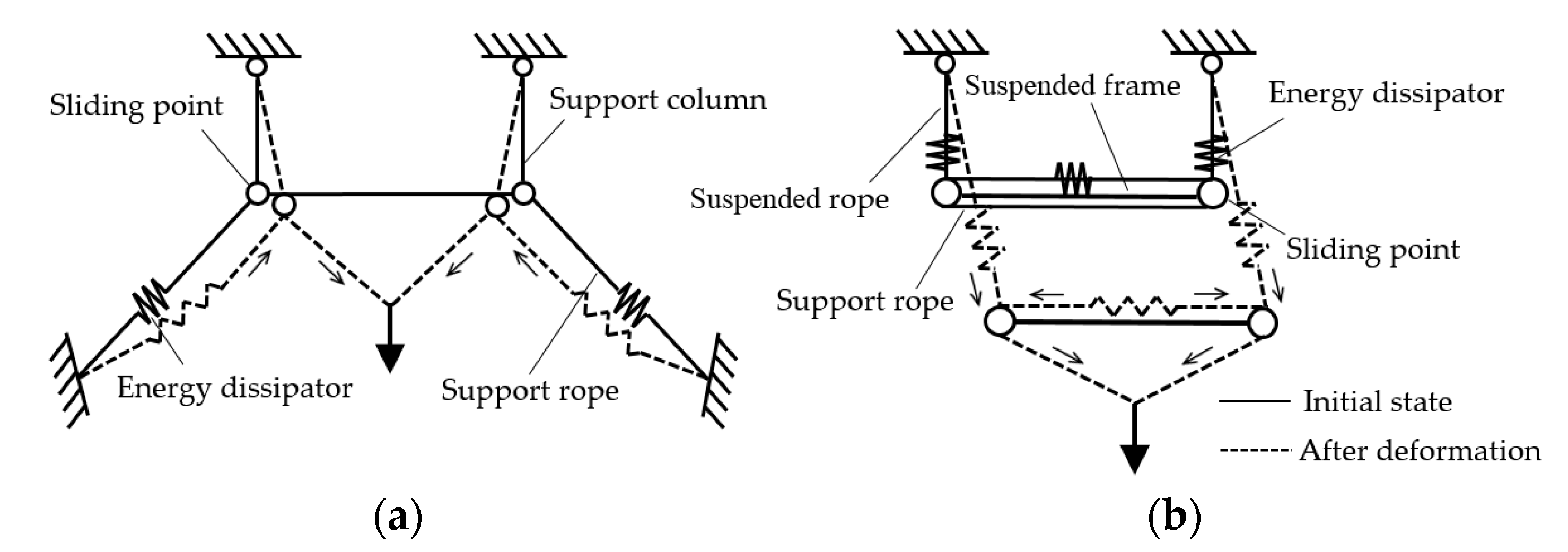
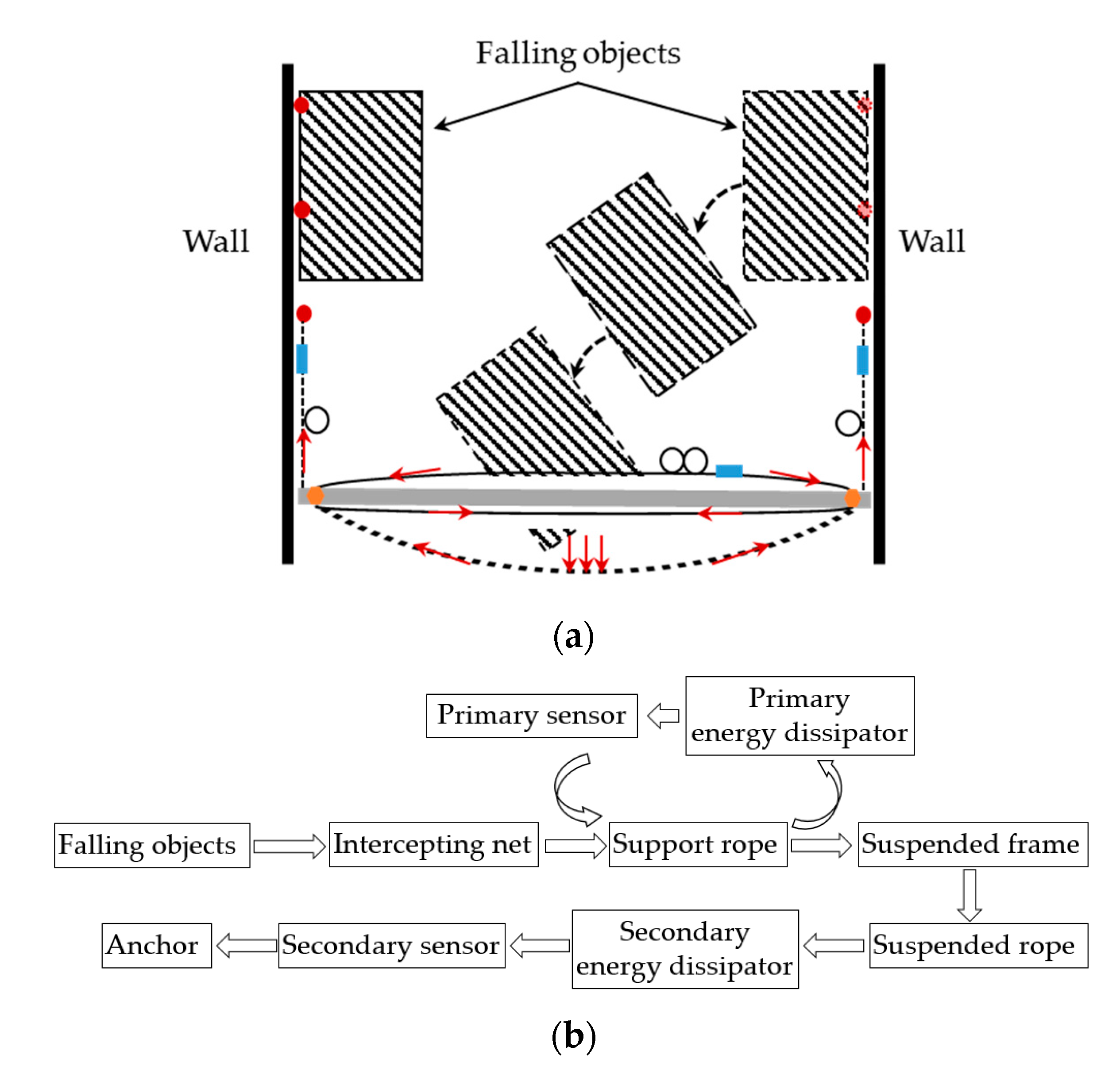
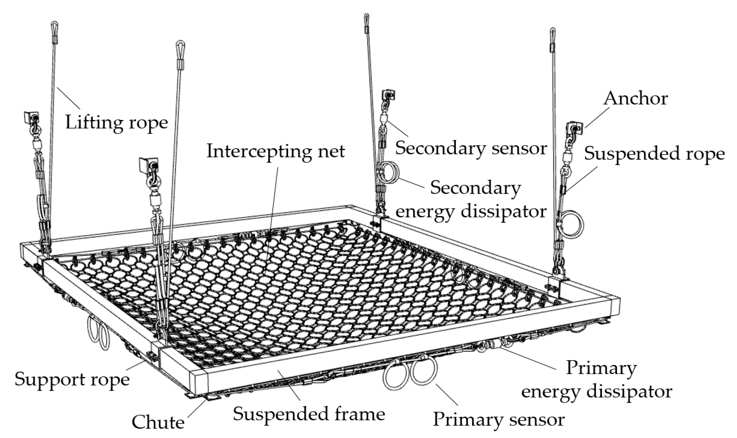
3.1. Composition

The envisaged high-fall flexible protection system consists of intercepting net, wire rope, suspended frame, energy dissipators, sensor, and other connecting and anchoring components (Figure 2). The head and tail of the wire rope are sleeved to form a ring support rope, which is hung in the chute under the suspended frame. The inner side of the support rope connects with the intercepting net through shackles while the outer side connects with energy dissipators and sensors. One end of the wire rope is anchored, and the other end connects with the suspended frame to form a suspended rope, which connects to the energy consumer and sensor. The system anchored on the inner wall of buildings can protect the falling objects above it.

3.2. Working Mechanism

The comparison of the working mechanism between the high-fall flexible protection system and the traditional passive flexible protection system shows in Figure 3. The traditional flexible protection system [31,32,33,34,35] (Figure 3a) is generally composed of four parts: the support structure, the intercepting net, an energy consumption device, and the anchor structure; when it works, the support rope slides along the end of the support column to drive the energy dissipators connected with it to undergo large deformations to realize energy consumption and transmit the force to the anchor. Meanwhile, the steel column has a slight deflection and transmits the force to the anchor of the column base. It needs a large number of anchors and anchoring space.
The high-fall flexible protection system adopts the self-anchored connection method (Figure 3b), that is the support rope connects to form a closed-loop force transmission path, without additional anchors. The force transmission diagram of the system shows in Figure 4a and the force transmission path is in Figure 4b. When impacted by falling objects, the intercepting net deforms and contracts to the middle, the shackle slides along the support rope and pulls the support rope to contract with the mesh, and the support rope starts the primary energy dissipators and slides to the inner side along the chute. Concurrently, the force is transferred to the suspended frame and then to the anchor of the ultra-high-rise buildings through the suspended rope and starts the secondary energy dissipators.

4. Design Method

4.1. Energy Matching

The traditional passive flexible protection system [25,31,33] is generally subject to high-velocity remote impact (the impact velocity of the standard test drop hammer is 25 m/s), so the maximum kinetic energy of the impact body is considered as the nominal protection energy level in the design, and the potential energy change in the impact body after contact with the intercepting net can be ignored. However, when the formwork system falls, the high-fall flexible protection system is close to the construction formwork, and the impact velocity is low, the nominal protection energy level should be the maximum potential energy change between the construction formwork and the protection system.
When the high-fall flexible protection system is impacted, the total energy ET can be expressed by Formula (1), where m is the mass of the fallen body—h0 is the initial protection height (the distance between the fallen body and the intercepting net), hmax is the maximum impact displacement of the system (including the elongation of the secondary energy dissipators and the intercepting net deformation), and ΔE is the potential energy change in the protection system itself. ET can also express as the work performed by the impact contact force F(h) between the fallen body and intercepting net along the impact direction h. ET can also be expressed as the superposition of energy consumption of each component, as shown in the Formula (2), which is mainly divided into two parts: one is the internal energy EI of deformation of each component of the system, and the other is the energy consumption EM of damping, friction, and other motions.
E T = m g ( h 0 + h max ) + Δ E = 0 h max F ( h ) d h + Δ E
E T = E I + E M
The research shows that under the impact of nominal protection energy level, EM of flexible protection system is far less than EI, which can ignore in design [21] EI is contributed by the deformation of the energy dissipator, intercepting net, suspended frame, and wire ropes. The deformation of the suspended frame and the wire rope should stay in the elastic stage to ensure the safety of the system, so the energy consumption of these two parts can disregard. The energy balance equation can be simplified as Formula (3), where EN is the energy consumption of the intercepting net, and ED is the total energy consumption of the energy dissipators.
E I = E N + E D
Guo [29] carried out a series of mesh burst tests of intercepting nets and obtained the bursting force–displacement relation of some specifications of interception nets that typically use under rigid boundaries. The characteristics of the intercepting net under the true flexible boundary are figured out by the mesh burst tests at the Protective Structure Test Center of Southwest Jiaotong University. According to the mesh burst tests of rigid boundary [29], the boundary changed into the flexible boundary of the wire rope (Figure 5), and the mesh ring with wire rope passing through the edge is anchored on the burst test frame. The mesh test piece is square, the number of mesh edge rings is 7, the diameter of the mesh ring wire rope is 3 mm, and the diameter of the mesh ring is 300 mm. The plug is a spherical crown shape, and the loading rate of the plug is 8 mm/s. The tension sensor was used to record the jacking pressure, and the laser displacement meter was used to record the jacking displacement.
The force–displacement curve obtained from the test shows in Figure 6. The force–displacement characteristics of the intercepting net under the flexible boundary condition are similar to those under the rigid boundary condition [29]. There are two stages of features: the deformation in the first stage reaches more than 80% of the limit deformation, while the stress is only 10–20% of the braking force. In the second stage, the deformation increases slowly, while the internal force increases sharply. Due to the lateral deformation of the tensioned wire rope boundary caused by the pulling force of the mesh ring, the characteristics of the intercepting net under the flexible boundary in two stages are more significant, which manifested in the greater deformation of the mesh in the first stage and the larger braking force in the second stage. The true boundary of the intercepting net of the high-fall flexible protection system is the flexible boundary, which is in the first stage under normal working conditions, and the energy consumption is relatively small. EN can be ignored during engineering design. At present, the intercepting net adopts rigid boundary test parameters to design with the braking force and limit deformation. To simplify the design of the high-fall flexible protection system, the intercepting net also could adopt rigid boundary test data, which are conservative and safe according to this comparative test.
In the traditional flexible protection system, the energy consumption ratio of energy dissipators can reach more than 80% [31], and the larger the ratio, the smaller the damage to other parts of the system. During the design, the impact energy dissipated by the energy dissipators should be as much as possible, and other components only play the role of intercepting and force transmitting. The energy balance equation simplifies into Formula (4), the impact energy in the limit state is equal to the total energy consumption of the energy dissipators, equal to the sum of the integral of the actual working force F ( s i ) of each energy dissipator and the displacements, and further simplified into the sum of the product of the average working force FDi of each energy dissipator and its maximum stroke Si. Since it is extremely difficult to fully start the energy dissipators at the same time when it is working, the safety factor λ is introduced. λ represents the ratio of the nominal energy consumption capacity of all energy consumers in the system to the maximum impact energy that the system may be subjected to. λ is a number greater than 1 and should be taken based on the demand for protective safety surplus.
E T = λ E D = λ i = 0 n 0 S i F ( s i ) d s = λ i = 0 n F D i s i

4.2. Component Internal Force Balance

When the flexible protection system is impacted, the internal force response of the system is complex and nonlinear and is affected by many factors such as boundary stiffness, the performance of energy dissipator, tension degree of the intercepting net, sliding performance of the sliding joint, and so on [30,31]. The force balance equation does not have an ideal analytical solution, and the numerical solution is always obtained through the finite element method. Usually, this type of strong impact and large deformation structure is suitable for using the explicit integration method [41,42]. This method uses the central difference method to solve the displacement general solution at time t + Δt using the equilibrium conditions at time t. Generally, there is no problem of non-convergence and the computational resources occupied are also very small. According to the structural design principle, the resistance of each component should be greater than the internal force (Formula (5)), which shows in the following aspects: the breaking force R1 of the intercepting net should be greater than the impact force S1 of the falling object, the breaking force R2 of the wire rope shall be greater than its tensile force S2, and the stable bearing capacity R3 of the suspended frame shall be greater than its internal force S3.
S i < R i

4.3. Two-Level Energy Consumption Mechanism

When the system works, the tension force of the energy dissipator is equal to that of the connected wire rope, so connecting the tension sensor on the wire rope can monitor the working condition of the energy dissipator. To find the characteristics of the GS-8002 ring-type energy dissipator used in the system, four groups of quasi-static tensile tests (Figure 7) were carried out. One end of the ring-type energy dissipator was fixed on the ground, and the other end was sleeved with the pull head of the tensile testing machine, with a tensile rate of 10 mm/s.
The GS-8002 ring-type energy dissipator has three-stage characteristics (Figure 8) that are similar to the GS-8000-type [34] ring-type energy dissipator. The first stage is when the ring-type energy dissipator is just under tension and overcomes the friction force of the aluminum sleeve to produce a small disturbance. At this stage, the tension force increases rapidly while the displacement is small, and the energy consumption is very small. In the second stage, when the tension reaches a certain limit (starting point), the annular energy dissipator undergoes plastic deformation and gradually reduces the pipe diameter, and the tension increases slowly while the displacement increases rapidly, and dissipates a large amount of energy. The third stage is when the ring diameter of the energy dissipator is deformed to a certain extent, and it is hard to continue to deform. In this stage, the tensile stiffness of the energy dissipator increases, the tensile force increases sharply from the inflection point, and the growth rate of deformation decreases rapidly.
When the monitoring force is less than the average working tension force of the energy dissipator, it means that the energy dissipator is not started and is in the first stage. When the monitoring force is approximately equal to the average working tension force of the energy dissipator, it indicates that the energy dissipator is started and is in the second stage. When the monitoring force suddenly increases sharply, which is far greater than the average working tension force of the energy dissipator, it means that the energy dissipator has reached the limit displacement and will not continue to consume energy, and the impact energy will dissipate by other components of the system. Therefore, the impact energy of the system can be roughly counted by monitoring the working condition of each energy dissipator.
Based on the characteristics of the above energy dissipators, the energy dissipators are arranged on the support ropes and suspended ropes to form a two-level energy consumption and monitoring mechanism. The primary energy dissipators on the support ropes improve the energy consumption capacity through the series ring energy dissipator [32], and the average working tension force is equivalent to that of a single ring energy dissipator. The secondary energy dissipators on the suspended ropes improve the energy consumption capacity and double the starting force through the parallel ring energy dissipators.
The primary energy dissipators with a low starting force and the secondary energy dissipator with a high starting force constitute the two-stage energy consumption mechanism of the system. In addition, the four-level discrimination principle of falling object impact energy is formed through the monitoring data of the tension sensors. According to whether the two-stage energy dissipators are started or not, and whether the limit of displacement is reached, the scale of the falling accident divides into four levels as shown in Table 1. F1 and F2 in the table are the monitoring data of the primary and secondary tension sensors respectively, and S1 and S2 are the average working tension of the primary and secondary energy consumers, respectively.

5. System Simulation

5.1. Model Design

In the construction of the core tube of a super high-rise building [10], the formwork system used had a falling impact energy of about 650 kJ. According to Formula (4), the safety factor λ is taken as 1.2, and at least a total energy consumption of 780 kJ should be configured. Therefore, sixteen GS-8002 energy consumers are selected, with a total energy consumption capacity of 800 kJ. A high-fall flexible protection system was designed according to the above design method. The parallel connection of two GS-8002-type ring energy dissipators by the suspension rope increases the starting force of the energy dissipator, and the series connection of two GS-8002-type ring energy dissipators by the hanging rope increases the maximum deformation of the energy dissipator, thereby achieving two-stage energy consumption in the design method. The overall layout of the system is shown in Figure 9, with the conversion frame having a long side of 8.5 m, a short side of 7.5 m, and a sling length of 1 m. Verify the feasibility of the design method through numerical simulation.

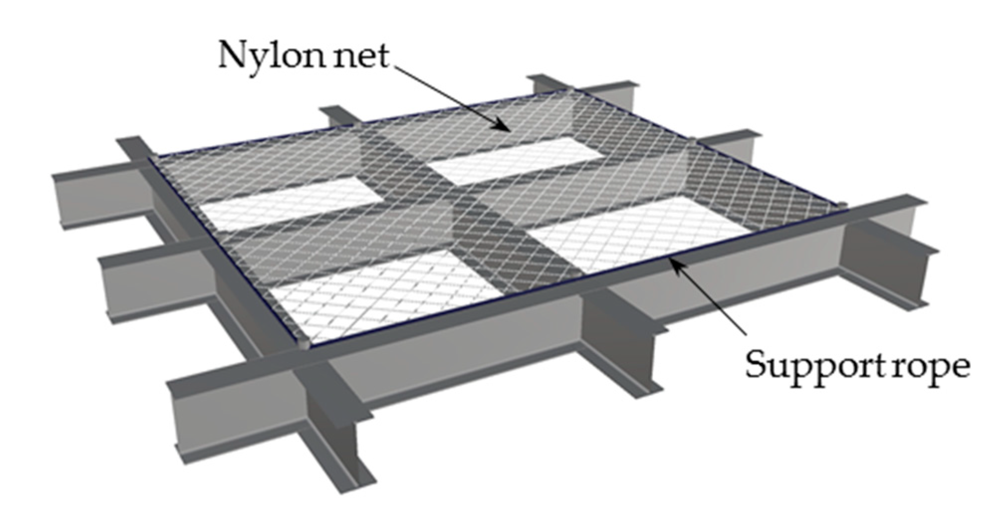
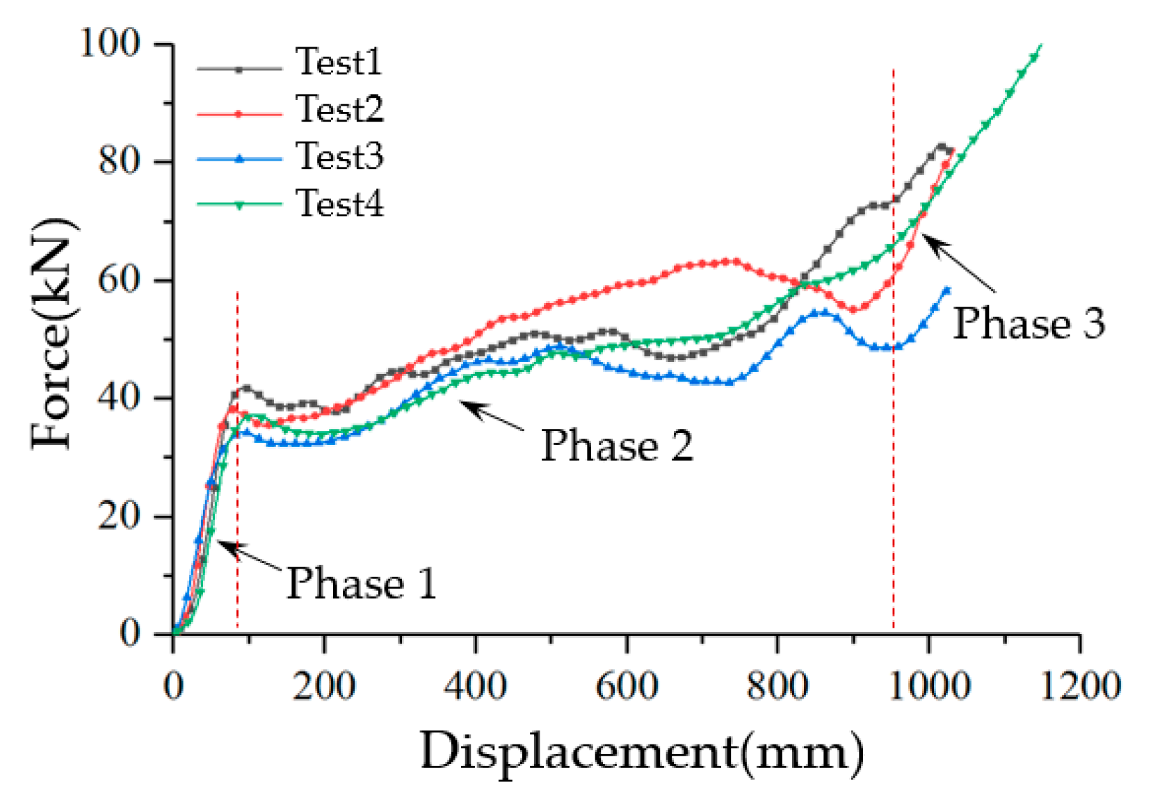
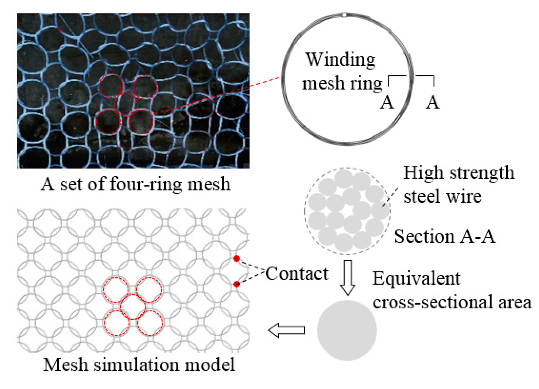
5.2. Simulation of Interception Net

The intercepting net forms by connecting a set of four mesh rings and the mesh rings are made of multi-strand high-strength steel wires. In the numerical calculation, use the annular beam element to establish the model, concerning the equivalent constitutive model proposed by Xu [30]. The elastic modulus reduces to simulate the macroscopic mechanical behavior of the mesh. In addition, they use the equivalent method of cross-sectional area to simplify the mesh ring section, and set general self-contact between the mesh rings (Figure 10).

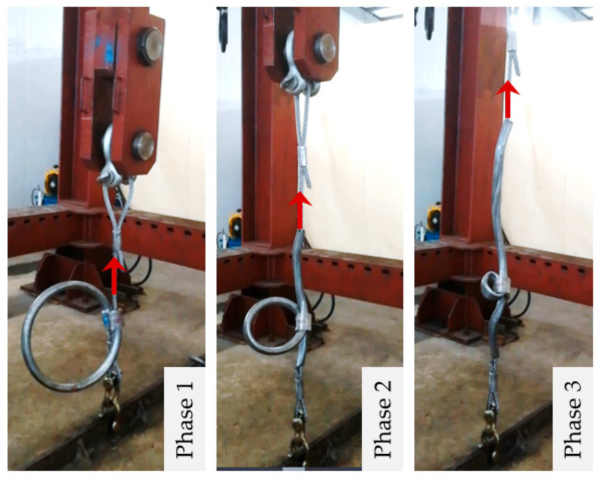
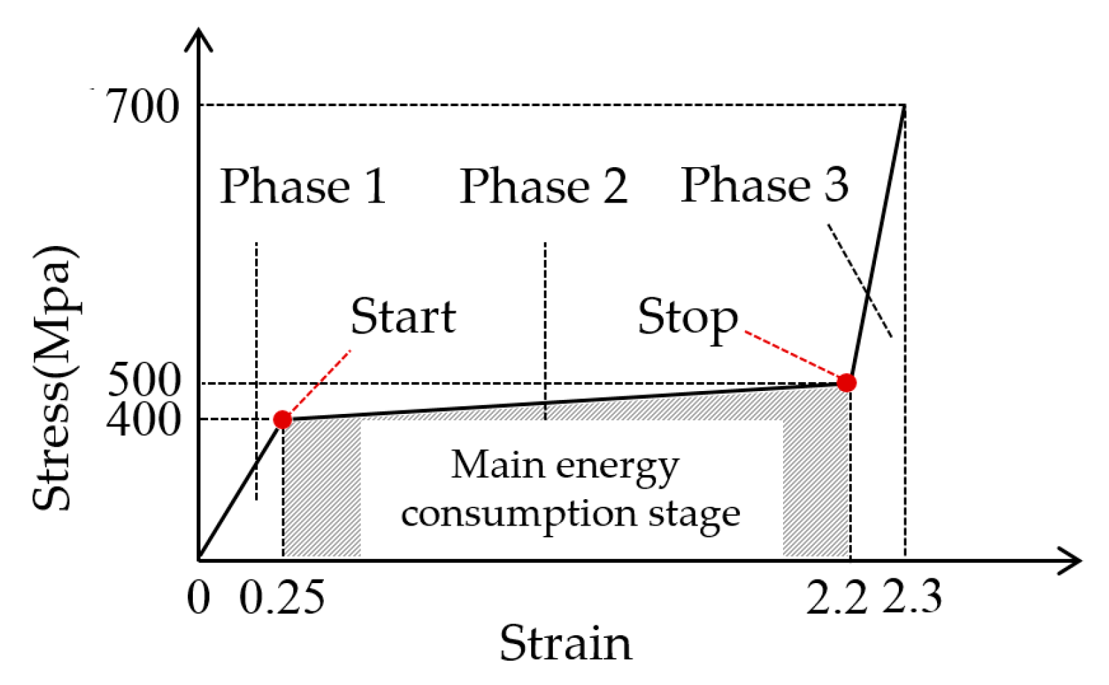
5.3. Simulation of Energy Dissipator

The energy dissipator is simulated by the beam element with a piecewise linear plasticity material model. The force-displacement curve (Figure 8) obtained from the quasi-static tensile test is simplified into a three-stage model and can be converted into the simplified true stress-strain curve (Figure 11) according to the calculation Formula (6) [43].
ε = ln ( 1 + ε )
where ε is engineering strain, ε is real strain.

5.4. Finite Element Model

According to the model shown in Figure 8, the finite element dynamic calculation model is established in the LS-DYNA program [43]. The specifications and simulation parameters of each component are shown in Table 2. The connection part between the suspended frame and the suspended rope is subject to a large force, so the square tube with a section of 300 × 300 × 8 is used for the opposite side, and the square tube with a length of 180 × 180 × 6 is used for the other side, and the length and width of the frame are 8 m.
During impact calculation, beam-to-surface contact shall be set between the falling object and the intercepting net. General automatic contact is set between the shackle and intercepting net. A guided-cable contact is set between the shackle and the support rope. The safety belt unit is used to set sliding contact at the connection between the support rope and the suspended frame. The falling object and high-falling flexible protection system are set with universal automatic contact with the wall of the buildings.

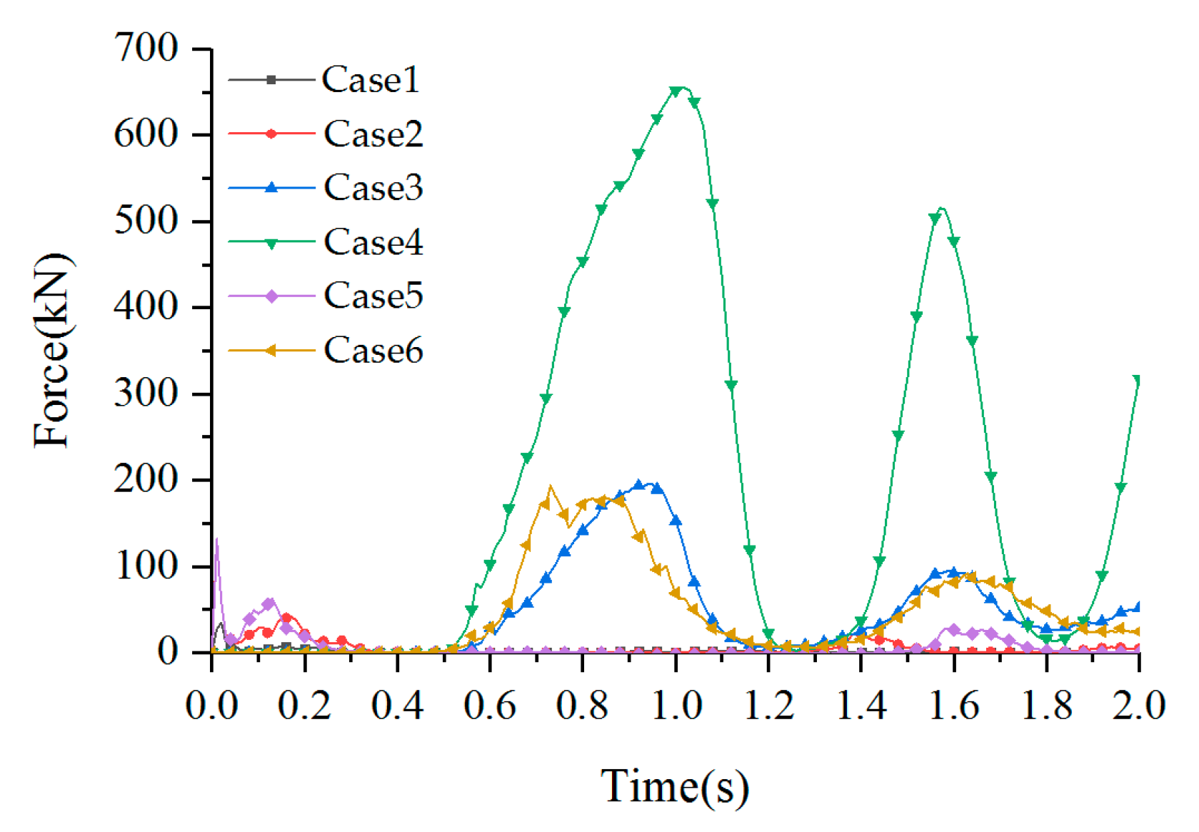
5.5. Simulation Cases

To test the practicability of the two-stage energy consumption mechanism, the first four calculation conditions shown in Table 3 corresponded to the four accident levels in Table 1. In Case 1 and Case 2, the falling object falls from the top of the framework system. To increase the calculation efficiency, the initial position of the falling object was set to be attached to the net, and its initial potential energy was converted into kinetic energy, which was given the initial velocity. In Case 3 and Case 4, the whole falling of the framework system was taken into consideration, and the initial position was the actual anchor position. The impact energy of the protection system was the theoretical calculation of the falling potential energy, which could be calculated according to the Formula (1). To find out the effect of the energy-consuming mechanism, the energy-dissipators under Case 1 and Case 3 were removed, forming Case 5 and Case 6, respectively.

6. Result Analysis

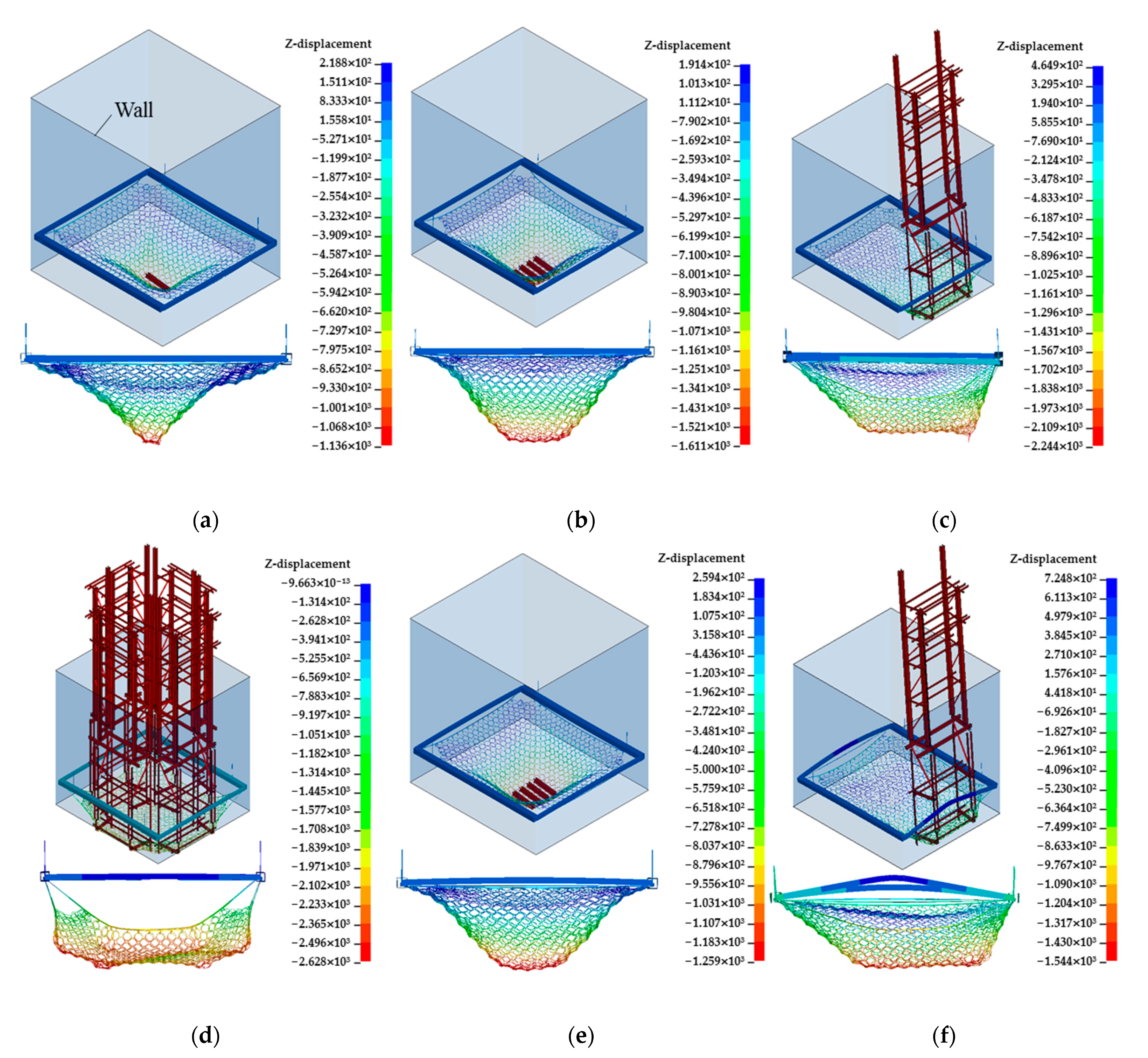
6.1. System Deformation

The intercepting deformation of the system from simulations under each impact case is shown in Figure 12. The system successfully intercepts the falling objects with a different impact energy from Case 1 to Case 5 and the components are not damaged. The suspended frame buckling is visible in Case 6, which indicates that the system without an energy dissipation mechanism cannot withstand the high energy impact.
Figure 13 also shows the front view of the deformation of the protective net. The net is impacted and contracted in a funnel shape. The shackles connected with the mesh around the mesh under Case 1 to Case 4 are pulled and slid along the support rope. The support rope connects the shackles and is pulled and the energy dissipators are started by the self-anchoring mechanism to realize large deformation. The overall deformation of the system is consistent with the expected situation. Compared with Case 2 and Case 3, the maximum displacement of Case 5 and Case 6 decreased by 21.8% and 31.2%, respectively. The system without energy dissipators is not “flexible” enough, and the deformation capacity decreased significantly.
In Case 1 and Case 2, small-scale objects impact the middle of the mesh span, and the system deformation law is consistent with the existing research [31,32,33]. Case 3 is that the single object impacts the edge of the mesh, and the system deformation and internal force distribution are extremely asymmetric. Case 4 is that the mass object impacts the four edges of the mesh symmetrically, and the stress in the middle of the mesh is small, The research on these two types of impact conditions is relatively rare, and the system can work normally, which shows that the system can cope with the randomness of a falling object impact.

6.2. Energy Consumption Distribution

The energy consumption ratio of system components under various cases shows in Table 4. The impact energy of Case 1 and Case 2 is small, the energy dissipators have not started, and the energy consumption of the mesh itself is relatively high. Case 3 is an eccentric impact, and the energy dissipators on the impact side start more. With the increase in impact energy, the proportion of energy consumption of energy dissipators keeps rising, and in Case 4 reaches 85.3%, which proves that the limit state design error based on system energy matching in this design method is small, and verifies the feasibility of energy matching design in this design method. In Case 5, the energy consumption mainly depends on the mesh. In Case 6, the buckling energy consumption of the suspended frame is relatively large; before the buckling of the suspended frame, the total impact energy is 111.6 kJ, that is, the ultimate energy consumption of the system without the energy dissipators is 111.6 kJ. The impact energy of Case 4 is 673.8 kJ, the energy consumption is 84.2%, and the system limit energy consumption can exceed 800 kJ.

6.3. Internal Force of Components

The time history of mesh impact forces under various cases are shown in Figure 13. When the falling object first contacts the mesh, the impact force reaches the peak value and gradually decreases after multiple rebounds. As shown in Figure 14, the time history of the tension force of the suspended rope in Case 3 and Case 4 is gradually attenuated under the energy consumption mechanism. Simultaneously, due to the eccentric impact in Case 3, the force on each rope is uneven, and the internal force near the impact side is large. The other cases are consistent with the law of Case 4, and the internal force response law of the support rope and the suspended rope is consistent. This phenomenon is consistent with the test law of the passive protection system [31,32,33].
The peak value of the internal force of each component of the system is shown in Table 5. The system components under Case 1 to Case 5 have a large surplus, and the overall structure is relatively safe. Because impact condition 3 is an asymmetric load, the stress at the impact side of the suspended frame is large, and the maximum stress exceeds condition 4, so the impact of eccentric impact should be fully considered in the design.
Compared with Case 5, the internal force of the support rope in Case 2 decreases by 59%, the internal force of the suspended rope decreases by 60.3%, and the stress of the suspended frame decreases by 63.6%. Under Case 6, the internal force of the wire rope reaches the breaking value, the stress of the suspended frame reaches the yield value, and the system fails.

6.4. Discussion

According to the energy consumption mechanism proposed in this paper, the energy consumption capacity of the system increases more than six times compared with the system without energy consumption. The simulation results verify the feasibility of the component force balance design in this design method. Meanwhile, the state of the energy dissipator is the same as that expected in Section 4.3 of this paper, which proves the effectiveness of the two-sage energy consumption mechanism in this design method. The energy consumption mechanism has an obvious effect on reducing the internal force of key components, so the energy consumption mechanism is indispensable in the design.
The high-fall flexible protection system is designed for the overall fall protection of formwork equipment in the construction of the core tube of ultra-high-rise buildings, and can also be used in the high-fall protection of other building structure openings. Compared to traditional protection systems (Table 6), the biggest advantage of the protection system proposed in this article is its higher energy consumption capacity. The disadvantage of this system is its high cost, so it can be combined with traditional protective nets to use this system in areas with high protection level requirements and traditional protective systems in areas with low protection level requirements.

7. Conclusions

(1)
This study set out to develop a high-fall flexible protection system with much stronger energy consumption than traditional protection systems, solving the problem of large-scale impact protection similar to the overall fall of mold equipment, thereby improving construction safety.
(2)
The novelty of the system lies in the use of steel wire mesh as the interception component and the use of energy dissipators as the energy-consuming component, achieving high energy consumption capacity.
(3)
The proposed design method considers system energy matching, component internal force balance, and two-stage energy consumption, which can achieve the scientific and quantitative design of high-altitude flexible protection systems.
(4)
These simulations confirmed that compared with the system without an energy dissipation mechanism, the system with a tensile yield energy dissipation mechanism can reduce the internal force of its key components by about 60% and increase the anti-falling impact capacity more than six times.
(5)
The study is limited by the lack of practical engineering applications. The convenience and economy of the system have not been verified yet.
(6)
Future studies should pay attention to the high energy impact protection of non-opening parts, and carry out special research on its application to the high-fall damage protection of construction personnel.

Author Contributions

Conceptualization, L.L. (Linxu Liao) and Z.Y.; Methodology, L.L. (Linxu Liao) and Z.Y.; Validation, L.G.; Formal analysis, L.L. (Linxu Liao) and L.L. (Liru Luo); Writing—original draft preparation, L.L. (Linxu Liao); Writing—review and editing, Z.Y., X.T., and D.L.; Funding acquisition, D.L. All authors have read and agreed to the published version of the manuscript.

Funding

This research received no external funding.

Data Availability Statement

Not applicable.

Conflicts of Interest

The authors declare no conflict of interest.

References

  1. OSHA (Occupational Safety and Health Administration). OSHA Commonly Used Statistics. 2019. Available online: https://www.osha.gov/data/commonstats (accessed on 7 May 2021).
  2. OSHA (Occupational Safety and Health Administration). Safety and Health Regulations for Construction: Fall Protection (Standard 29 CFR 1926, SubpartM). Available online: https://www.osha.gov/lawsregs/regulations/standardnumber/1926/1926.502 (accessed on 23 May 2021).
  3. HSE, 2020. Health and Safety Executive. Workplace Fatal Injuries in Great Britain. Available online: http://www.hse.gov.uk/statistics/pdf/fatalinjuries.pdf (accessed on 5 March 2023).
  4. Ma, Z. Statistical analysis of safety production accidents in construction field. Architecture 2022, 3, 52–55. [Google Scholar]
  5. Safework, A. Work-related Traumatic Injury Fatalities, Australia. 2019. Available online: https://www.safeworkaustralia.gov.au/doc/work-related-traumatic-injury-fatalities-australia-2019 (accessed on 6 March 2023).
  6. Ling, F.Y.Y.; Liu, M.; Woo, Y.C. Construction fatalities in Singapore. Int. J. Project Manag. 2009, 27, 717–726. [Google Scholar] [CrossRef]
  7. Korea Occupational Safety and Health Agency. 2018 Industrial Accident Status Analysis. 2018. Available online: https://www.kosha.or.kr/english/index.do (accessed on 6 March 2023).
  8. Kim, J.M.; Son, K.; Yum, S.G.; Ahn, S. Analyzing the risk of safety accidents: The relative risks of migrant workers in construction industry. Sustainability 2020, 12, 5430. [Google Scholar] [CrossRef]
  9. Ren, G. The removal of the anti-fall device led to the fall of the climbing frame and the illegal cross-operation caused the accident to expand—Analysis of a Larger Accident of Falling of Attached Lifting Scaffolding in “3.21” Attached Lifting Scaffolding of AVIC Baosheng Offshore Engineering Cable Project in Yangzhou, Jiangsu Province. Jilin Labor Prot. 2019, 9, 39–41. [Google Scholar]
  10. Office of the Work Safety Committee of the State Council. Notification from the Office of the State Council Safety Commission on the “9.10” Major Attached Scaffold Fall Accident at the Kaixuan Building Construction Site on Xuanwu Road, Xi’an City, Shaanxi Province. In Proceedings of the Gazette of the State Administration of Work Safety and the State Administration of Coal Mine Safety, Xi’an, China, 14–15 October 2011. [Google Scholar]
  11. Zhong, B.; Pan, X.; Love, P.E.D.; Ding, L.; Fang, W. Deep learning and network analysis: Classifying and visualizing accident narratives in construction. Autom. Constr. 2020, 113, 103089. [Google Scholar] [CrossRef]
  12. Ma, F.; Zhang, D.; Wang, Z.; Chen, X.; Jiang, L. Risk Assessment of Falling Objects from Façades of Existing Buildings. Buildings 2023, 13, 190. [Google Scholar] [CrossRef]
  13. Ansari, R.; Dehghani, P.; Mahdikhani, M.; Jeong, J. A Novel Safety Risk Assessment Based on Fuzzy Set Theory and Decision Methods in High-Rise Buildings. Buildings 2022, 12, 2126. [Google Scholar] [CrossRef]
  14. Halabi, Y.; Xu, H.; Long, D. Causal factors and risk assessment of fall accidents in the U.S. construction industry: A comprehensive data analysis (2000–2020). Saf. Sci. 2022, 146, 105537. [Google Scholar] [CrossRef]
  15. Newaz, M.T.; Ershadi, M.; Carothers, L.; Jefferies, M.; Davis, P. A review and assessment of technologies for addressing the risk of falling from height on construction sites. Saf. Sci. 2022, 147, 105618. [Google Scholar] [CrossRef]
  16. Semeykin, A.Y.; Klimova, E.; Nosatova, E.; Khomchenko, Y.V. Using of automated risk assessment systems to ensure the safety of personnel at construction sites. IOP Conf. Ser. Mater. Sci. Eng. 2020, 945, 012022. [Google Scholar] [CrossRef]
  17. Łabęd’z, P.; Skabek, K.; Ozimek, P.; Nytko, M. Histogram Adjustment of Images for Improving Photogrammetric Reconstruction. Sensors 2021, 21, 4654. [Google Scholar] [CrossRef]
  18. Lu, Y.; Gong, P.; Tang, Y.; Sun, S.; Li, Q. BIM-integrated construction safety risk assessment at the design stage of building projects. Autom. Constr. 2021, 124, 103553. [Google Scholar] [CrossRef]
  19. Wang, Z.; Wu, Y.; Yang, L.; Thirunavukarasu, A.; Evison, C.; Zhao, Y. Fast personal protective equipment detection for real construction sites using deep learning approaches. Sensors 2021, 21, 3478. [Google Scholar] [CrossRef] [PubMed]
  20. Zuluaga, C.M.; Albert, A.; Winkel, M.A. Improving safety, efficiency, and productivity: Evaluation of fall protection systems for bridge work using wearable technology and utility analysis. J. Construct. Eng. Manag. 2020, 146, 04019107. [Google Scholar] [CrossRef]
  21. Çelik, G.T.; Aydınlı, S.; Bazaati, S. Safety net applications in developing countries: Turkey and Iran case study. J. Constr. Eng. Manag. Innov. 2021, 4, 12–21. [Google Scholar] [CrossRef]
  22. Filho, M.C.A.; Serra, S.M.B. Comparison between collective protective systems in Brazil: Safety platforms and safety net type V. SN Appl. Sci. 2020, 2, 2153. [Google Scholar] [CrossRef]
  23. Eulogio, E.S.; Más, R.I. Energy Absorption of Safety Nets in Building Construction [C/OL]//Structures under Shock and Impact the New Forest; WIT Press: Southampton, UK, 2006; pp. 421–429. [Google Scholar]
  24. Chen, Y. Experimental Research and Numerical Simulation of Protective Performance of Safety Nets in High-Rise Building Construction; Southwest Jiaotong University: Chengdu, China, 2022. [Google Scholar]
  25. Yu, Z.X.; Zhao, L.; Liu, Y.P. Studies on flexible rockfall barriers for failure modes, mechanisms and design strategies: A case study of western china. Landslides 2019, 16, 347–362. [Google Scholar] [CrossRef]
  26. Darve, F.; Li, X.; Zhao, J. A Unified CFD-DEM Approach for Modeling of Debris Flow Impacts on Flexible Barriers. Int. J. Numer. Anal. Methods Geomech. 2018, 42, 1643–1670. [Google Scholar]
  27. Jin, Y.-T.; Yu, Z.-X.; Luo, L.-R.; Zhang, L.-J.; Xu, H.; Qi, X. A study on energy dissipation mechanism of a guided flexible protection system under rockfall impact. J. Vib. Shock 2021, 40, 177–185+192. [Google Scholar]
  28. Qi, X.; Yu, Z.-X.; Zhang, L.-J.; Xu, H.; Li, Z.-M. Normalization analysis of puncture force of steel wire ring net. J. Vib. Shock 2021, 40, 178–186. [Google Scholar]
  29. Guo, L.-P.; Yu, Z.-X.; Luo, L.-R.; Qi, X.; Zhao, S.-C. An Analytical Method of Puncture Mechanical Behavior of Ring Nets Based on the Load Path Equivalence. Eng. Mech. 2020, 37, 129–139. [Google Scholar]
  30. Xu, H.; Gentilini, C.; Yu, Z.; Qi, X.; Zhao, S. An energy allocation based design approach for flexible rockfall protection barriers. Eng. Struct. 2018, 173, 831–852. [Google Scholar] [CrossRef]
  31. Zhao, S.C.; Yu, Z.X.; Wei, T.; Qi, X. Test study of force mechanism and numerical calculation of safety netting system. China Civ. Eng. J. 2013, 46, 122–128. [Google Scholar]
  32. Qi, X.; Xu, H.; Yu, Z.; Zhao, L.; Meng, Q. Dynamic Mechanical Property Study of Break Rings in Flexible Protective System. Eng. Mech. 2018, 35, 188–196. [Google Scholar]
  33. Yu, Z.-X.; Zhang, L.-J.; Luo, L.-R.; Jin, Y.-T.; Zhao, L.; Qi, X.; Zhao, S.-C. Study on impact resistance of a resilient steel canopy protection system. Chin. J. Rock Mech. Eng. 2020, 39, 2505–2516. [Google Scholar]
  34. Wang, M.; Shi, S.; Yang, Y. Static tensile test and FEM dynamic simulation for a ring-brake energy disspater. J. Vib. Shock 2011, 30, 188–193. [Google Scholar]
  35. Gottardi, G.; Govoni, L. Full-scale Modelling of Falling Rock Protection Barriers. Rock Mech. Rock Eng. 2010, 43, 261–274. [Google Scholar] [CrossRef]
  36. Zhao, Y.; Yu, Z.; Zhao, S. Numerical computing method for a flexible passive network structure with multi-span distributed ring-net. J. Vib. Shock 2019, 38, 211–219. [Google Scholar]
  37. Yu, Z.; Luo, L.; Liu, C. Dynamic response of flexible rockfall barriers with different block shapes. Landslides 2021, 18, 2621–2637. [Google Scholar] [CrossRef]
  38. Qi, X.; Xu, H.; Yu, Z. Full-scale test and numerical simulation of guided flexible protection system under a blasting load. Environ. Eng. Geosci. 2020, 26, 243–256. [Google Scholar] [CrossRef]
  39. Zhao, L.; Yu, Z.X.; Liu, Y.P. Numerical simulation of responses of flexible rockfall barriers under impact loading at different positions. J. Constr. Steel Res. 2020, 167, 105953. [Google Scholar] [CrossRef]
  40. Wang, L.; Zhang, X.; Wei, X.; Liang, W.; Zhang, W. Research and Application of Safety Net Hanging Technology in Steel Structure Construction of Super Tall Buildings. Constr. Technol. 2015, 44, 34–36. [Google Scholar]
  41. Noh, G.; Bathe, K.J. An explicit time integration scheme for the analysis of wave propagations. Comput. Struct. 2013, 129, 178–193. [Google Scholar] [CrossRef]
  42. Noh, G.; Ham, S.; Bathe, K.J. Performance of an implicit time integration scheme in the analysis of wave propagations. Comput. Struct. 2013, 123, 93–105. [Google Scholar] [CrossRef]
  43. Livermore Software Technology Corporation (lstc), LS-DYNA_Manual_Volume_I_R11. 2018. Available online: https://ftp.lstc.com/anonymous/outgoing/jday/manuals/LS-DYNA_Manual_Volume_I_R11.pdf (accessed on 5 March 2023).
Figure 1. Existing protection system.
Buildings 13 01376 g001
Figure 2. Composition of the system.
Buildings 13 01376 g002
Figure 3. Working mechanism. (a) Traditional systems (b) The high-fall flexible protection system.
Buildings 13 01376 g003
Figure 4. Force transmission. (a) Force transmission diagram. (b) Force transmission path.
Buildings 13 01376 g004
Figure 5. Mesh burst test.
Buildings 13 01376 g005
Figure 6. Force–displacement relationship.
Buildings 13 01376 g006
Figure 7. Decompression ring static test.
Buildings 13 01376 g007
Figure 8. Force–displacement relationship of GS-8002-type decompression ring.
Buildings 13 01376 g008
Figure 9. System design.
Buildings 13 01376 g009
Figure 10. Ring net simulation.
Buildings 13 01376 g010
Figure 11. True stress–strain curve of GS-8002-type decompression ring.
Buildings 13 01376 g011
Figure 12. System deformation. (a) Case 1. (b) Case 2. (c) Case 3. (d) Case 4. (e) Case 5. (f) Case 6.
Buildings 13 01376 g012
Figure 13. Impact force of the intercepting net.
Buildings 13 01376 g013
Figure 14. Case 3 internal force of suspended rope. (a) Case 3. (b) Case 4.
Buildings 13 01376 g014
Table 1. Classification of high-fall accidents by the status of the energy dissipators.
Accident LevelDistinguish ConditionThe Status of the Energy Dissipators
Level 1 F 1 < S 1 The primary energy dissipators are not started.
Level 2 F 1 i S 1 i
F 2 < S 2
Some of the primary dissipators started but did not reach the limit displacement, and the secondary dissipators did not start.
Level 3 F 1 i > S 1 i
F 2 i S 2 i
The primary energy dissipators are all started, some reach the limit displacement, and some secondary energy dissipators are started but did not reach the limit displacement.
Level 4 F 1 i > S 1 i
F 1 i > S 1 i
The primary energy dissipators are all started, some reach the limit displacement, and the secondary energy dissipators are all started, some reach the limit displacement.
Table 2. Component specifications and simulation parameters.
ComponentSpecificationActual materialMaterial ModelType of Element
Intercepting netR16/3/300High-strength steel wirePiecewise_linear_plasticityBeam
Support rope1φ226 × 19s + iwrCable_discrete_beamBeam
Suspended rope1φ226 × 19s + iwrCable_discrete_beamBeam
Energy dissipatorGs-8002Q235Piecewise_linear_plasticityBeam
Suspended frameB200 × 8Q355Plastic_kinematicBeam
Building materials32#b(Channel steel)Q355RigidShell
FormworkClimbing formworkQ355RigidShell
Table 3. Calculation condition.
CasesFalling MaterialsMass (t)Initial Velocity (m/s)Energy Dissipator
Case 1A single building steel0.07518.78Yes
Case 2Some building steel0.3018.78Yes
Case 3A single climbing formwork4.940Yes
Case 4The whole climbing formwork19.760Yes
Case 5Some building steel0.3018.78No
Case 6A single climbing formwork4.940No
Table 4. Energy distribution of system.
CasesEnergy DissipatorIntercepting NetSuspended FrameOthersTotal
ValueRatioValueRatioValueRatioValueRatio
Case 14.330.38.358.50.32.11.39.114.2
Case 219331220.80.81.425.844.857.6
Case 310666211331.930.619.1160.6
Case 457585.3375.5131.948.87.3673.8
Case 5--15.226.94.98.636.564.556.6
Case 6--23.217.462.646.947.635.7133.4
Table 5. Component internal force.
CasesSupport RopeSuspended RopeIntercepting NetSuspended Frame
Force(kN)Limit (kN)Surplus (%)Primary
Energy
Dissipator Status
Force (kN)Limit (kN)Surplus (%)Secondary
Energy Dissipator Status
Force (kN)Limit (kN)Surplus (%)Stress (Mpa)Limit (Mpa)Surplus (%)
Case 14828483.1Phase 117.828493.7Phase 134.692496.329.734591.4
Case 270.928475.0Phase 1 and Phase 230.428489.3Phase 113192485.749.234585.7
Case 311728458.8Phase 2 and Phase 314328449.6Phase 1 and Phase 219892478.622634534.5
Case 413828451.4Phase 2 and Phase 317728437.7Phase 2 and Phase 365592429.119134544.6
Case 517328439.1-76.528473.1-13192485.813534560.9
Case 62842840-16128443.3-194924793453450
Table 6. Performance Comparison.
Main Energy-Consuming ComponentsProtection CapabilityCost
“V-type” safety nets [23]nets7.7 kJlow
High-strength nylon nets [24]nets26.3 kJlow
The proposed systemEnergy dissipators673.8 kJhigh
Disclaimer/Publisher’s Note: The statements, opinions and data contained in all publications are solely those of the individual author(s) and contributor(s) and not of MDPI and/or the editor(s). MDPI and/or the editor(s) disclaim responsibility for any injury to people or property resulting from any ideas, methods, instructions or products referred to in the content.

