
Investigation and Analysis of Stress and Deformation Monitoring of Long-Span Steel Roof Trusses


Abstract
:1. Introduction
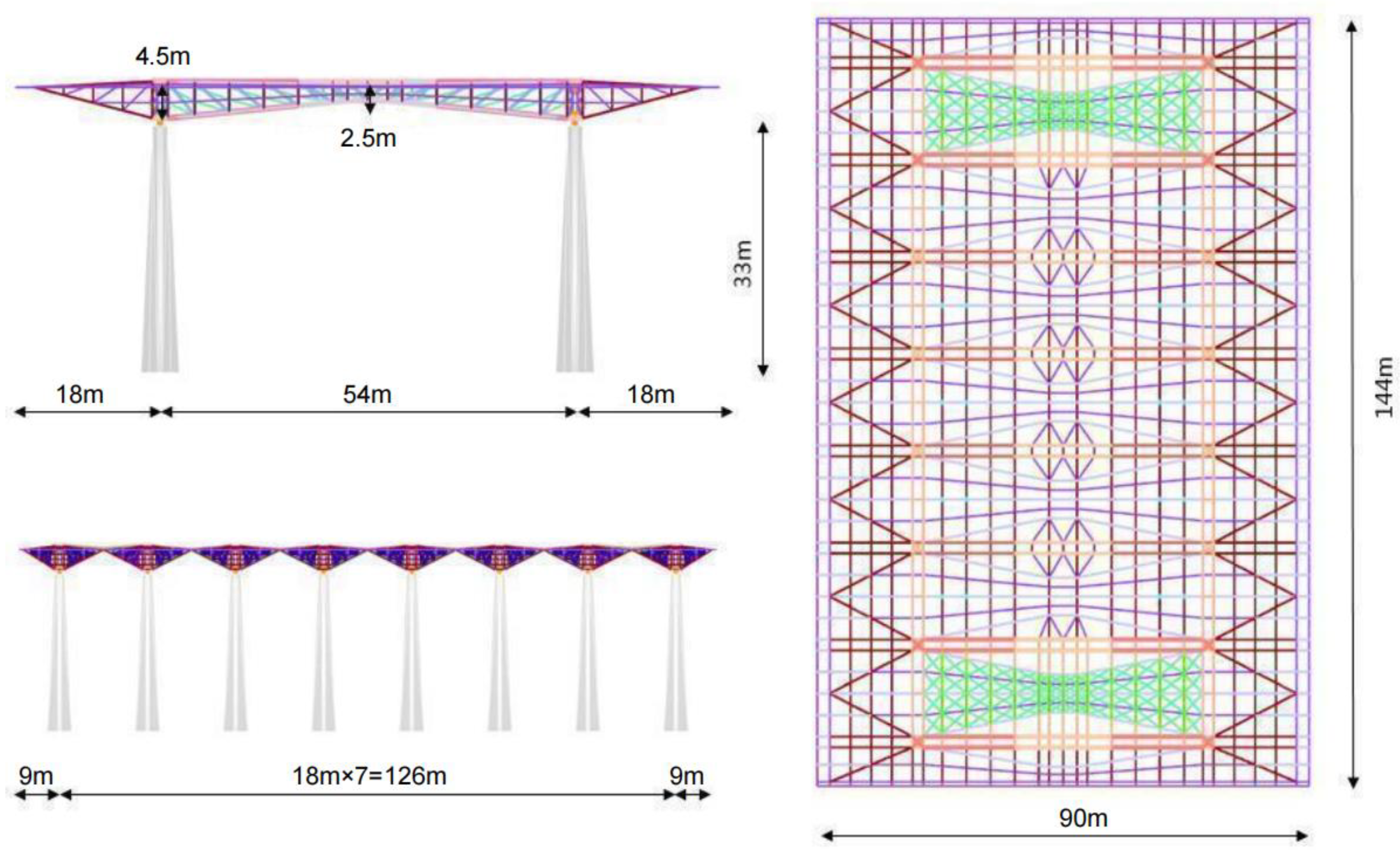
2. Project Profile
3. Engineering Structure Features
3.1. Complex Structural System
3.2. Complex Construction Process
3.3. Difficulty to Monitor
4. Finite Element Analysis
4.1. Model Development
4.2. Material Characteristic Parameter
4.3. Interpretation of Results
5. Monitoring the Construction Process
5.1. Stress Monitoring
5.2. Deformation Monitoring
6. Conclusions
Author Contributions
Funding
Institutional Review Board Statement
Informed Consent Statement
Data Availability Statement
Conflicts of Interest
References
- Zhang, Q.; An, Y.; Zhao, Z.; Fan, F.; Shen, S. Model selection for super-long span mega-latticed structures. J. Constr. Steel Res. 2019, 154, 1–13. [Google Scholar] [CrossRef]
- Su, N.; Peng, S.; Hong, N. Analyzing the background and resonant effects of wind-induced responses on large-span roofs. J. Wind Eng. Ind. Aerod. 2018, 183, 114–126. [Google Scholar] [CrossRef]
- Dong, S.; Zhao, Y.; Xing, D. Application and development of modern long-span space structures in China. Front. Struct. Civ. Eng. 2012, 6, 224–239. (In Chinese) [Google Scholar] [CrossRef]
- Chen, J.; Xiong, J.; Li, G. Acceleration response spectrum for predicting vibrations of long-span structures due to human running load. Eng. Mech. 2017, 34, 173–181. [Google Scholar] [CrossRef]
- Chen, Y.; Zhou, D.; Gui, L. Wind pressure simulation and key influence factors analysis of Mexico-Hat like spatial structures. J. Vib. Shock. 2013, 32, 37–40. (In Chinese) [Google Scholar]
- Li, T.; Yang, Q.; Ishihara, T. Unsteady aerodynamic characteristics of long-span roofs under forced excitation. J. Wind Eng. Ind. Aerod. 2018, 181, 46–60. [Google Scholar] [CrossRef]
- Wang, H.; Zhang, Y.; Mao, J.; Wan, H.; Tao, T.; Zhu, Q. Modeling and forecasting of temperature-induced strain of a long-span bridge using an improved Bayesian dynamic linear model. Eng. Struct. 2019, 192, 220–232. [Google Scholar] [CrossRef]
- Liang, L.; Li, X.; Zheng, J.; Lei, K.; Qin, J. Structure-borne noise from long-span steel truss cable-stayed bridge under damping pad floating slab: Experimental and numerical analysis. Appl. Acoust. 2020, 157, 106988. [Google Scholar] [CrossRef]
- Diana, G.; Fiammenghi, G.; Belloli, M.; Rocchi, D. Wind tunnel tests and numerical approach for long span bridges: The Messina bridge. J. Wind Eng. Ind. Aerod. 2013, 122, 38–49. [Google Scholar] [CrossRef]
- Lee, S.; Yhim, S. Dynamic behavior of long-span box girder bridges subjected to moving loads: Numerical analysis and experimental verification. Int. J. Solids Struct. 2005, 42, 5021–5035. [Google Scholar] [CrossRef]
- Kim, Y.; Park, J.; Oh, B.; Cho, T.; Kim, J.; Kim, S.; Park, H. Practical wireless safety monitoring system of long-span girders subjected to construction loading a building under construction. Measurement 2019, 146, 524–536. [Google Scholar] [CrossRef]
- Chen, Z.; Zong, L.; Ding, Y.; Shi, Y. Improved physical theory model for strut members in long-span spatial structures. J. Constr. Steel Res. 2019, 153, 85–100. [Google Scholar] [CrossRef]
- Feng, B.; Wang, X.; Wu, Z. Fatigue life assessment of FRP cable for long-span cable-stayed bridge. Compos. Struct. 2019, 210, 159–166. [Google Scholar] [CrossRef]
- Santana, M.; Gonçalves, P.; Silveira, R. Stability and load capacity of an elasto-plastic pyramidal truss. Int. J. Solids Struct. 2019, 171, 158–173. [Google Scholar] [CrossRef]
- Feng, L.; Xiong, J.; Yang, L.; Yu, G.; Yang, W.; Wu, L. Shear and bending performance of new type enhanced lattice truss structures. Int. J. Mech. Sci. 2017, 134, 589–598. [Google Scholar] [CrossRef]
- Zhu, Q.; Xu, Y.; Shum, K. Stress-level buffeting analysis of a long-span cable-stayed bridge with a twin-box deck under distributed wind loads. Eng. Struct. 2016, 127, 416–433. [Google Scholar] [CrossRef]
- Mahmoud, Y.; Hassan, M.; Mourad, S.; Sayed, H. Assessment of progressive collapse of steel structures under seismic loads. Alex. Eng. J. 2018, 57, 3825–3839. [Google Scholar] [CrossRef]
- Chen, Z.; Wen, J.; Deng, D.; Dai, W.; Chen, S.; Lu, H.; Liu, L. Research on parametric vibration of a steel truss corridor under pedestrians excitation considering the time-delay effect. Buildings 2023, 13, 98. [Google Scholar] [CrossRef]
- Li, S.; Jiang, W.; Zhu, X.; Xie, X. Effect of localized defects on mechanical and creep properties for pyramidal lattice truss panel structure by analytical, experimental and finite element methods. Thin-Walled Struct. 2022, 170, 108531. [Google Scholar] [CrossRef]
- Li, X.; Pan, J.; Zhou, X. Impact resistance analysis and optimization of variant truss beam structure based on material properties. Materials 2021, 14, 5847. [Google Scholar] [CrossRef]
- Xu, Z.; Zhao, Y.; Deng, C.; Li, Q. Research on seismic isolation of truss string structure with rubber bearings considering relative rotation. Structure 2021, 33, 1428–1438. [Google Scholar] [CrossRef]
- Li, S.; Jiang, W.; Zhu, X.; Xie, X. Experimental and analytical analysis of mechanical properties for large-size lattice truss panel structure including role of connected structure. Materials 2021, 14, 5099. [Google Scholar] [CrossRef] [PubMed]
- Ministry of Construction of the People’s Republic of China. GB 50017-2017; Code for Design of Steel Structure. China Building Industry Press: Beijing, China, 2017.
- Ministry of Construction of the People’s Republic of China. GB 50755-2012; Code for Construction of Steel Structures. China Planning Press: Beijing, China, 2012.
- Ministry of Construction of the People’s Republic of China. JGJ 257-2012; Technical Specification for Cable Structures. China Building Industry Press: Beijing, China, 2012.
- Ministry of Construction of the People’s Republic of China. T/CECS 529-2018; Early Warning Threshold Standard for Structural Health Monitoring System of Long-Span Bridge. China Building Industry Press: Beijing, China, 2018.
- Ministry of Construction of the People’s Republic of China. JGJ 7-2010; Technical Specification for Space Frame Structures. China Building Industry Press: Beijing, China, 2010.


| Condition Number | Load Application |
|---|---|
| Condition 1 | D |
| Condition 2 | D + L |
| Condition 3 | D + L + 0.6WX |
| Condition 4 | D + L + 0.6WY |
| Condition 5 | 0.7D + WX |
| Condition 6 | 0.7D + WY |
| Load Case | X-Direction Displacement (mm) | Y-Direction Displacement (mm) | Z-Direction Displacement (mm) | Maximum Stress (MPa) | Minimum Stress (MPa) |
|---|---|---|---|---|---|
| Condition 1 | 0 | 0 | −31.78 | −31.54 | −14.84 |
| Condition 2 | 0 | 0 | −33.63 | −33.36 | −15.71 |
| Condition 3 | 0.92 | 0 | −32.71 | −32.46 | −15.30 |
| Condition 4 | 0 | 2.63 | −32.71 | −32.58 | −15.42 |
| Condition 5 | 1.53 | 0 | −29.53 | −29.32 | −13.82 |
| Condition 6 | 0 | 4.38 | −29.53 | −29.53 | −14.02 |
Disclaimer/Publisher’s Note: The statements, opinions and data contained in all publications are solely those of the individual author(s) and contributor(s) and not of MDPI and/or the editor(s). MDPI and/or the editor(s) disclaim responsibility for any injury to people or property resulting from any ideas, methods, instructions or products referred to in the content. |
© 2023 by the authors. Licensee MDPI, Basel, Switzerland. This article is an open access article distributed under the terms and conditions of the Creative Commons Attribution (CC BY) license (https://creativecommons.org/licenses/by/4.0/).
Share and Cite
Hui, C.; Jiao, Y.; Liu, M.; Hai, R. Investigation and Analysis of Stress and Deformation Monitoring of Long-Span Steel Roof Trusses. Buildings 2023, 13, 398. https://doi.org/10.3390/buildings13020398
Hui C, Jiao Y, Liu M, Hai R. Investigation and Analysis of Stress and Deformation Monitoring of Long-Span Steel Roof Trusses. Buildings. 2023; 13(2):398. https://doi.org/10.3390/buildings13020398
Chicago/Turabian StyleHui, Cun, Yongkang Jiao, Mingliang Liu, and Ran Hai. 2023. "Investigation and Analysis of Stress and Deformation Monitoring of Long-Span Steel Roof Trusses" Buildings 13, no. 2: 398. https://doi.org/10.3390/buildings13020398
APA StyleHui, C., Jiao, Y., Liu, M., & Hai, R. (2023). Investigation and Analysis of Stress and Deformation Monitoring of Long-Span Steel Roof Trusses. Buildings, 13(2), 398. https://doi.org/10.3390/buildings13020398