Abstract
As a sustainable alternative to steel and concrete, cross laminated timber (CLT) shear wall systems are getting increasingly popular in mid-rise and high-rise construction, and that imposes new challenges on their seismic performance. The conventional connections used in this system, such as steel hold-downs and angle brackets, are, however, susceptible to brittle failures, thus being inappropriate for use in structures in seismic regions. A series of innovative connections have therefore been proposed in recent years for achieving better seismic behaviours in CLT structures, characterised by an adequate capacity, significantly improved ductility and dissipative capacity, as well as more controllable ductile failure modes. This paper first reviews the recent studies of CLT shear wall systems and conventional connections. Connection systems and shear wall reinforcement methods that have been recently proposed for seismic resilient CLT structures are then introduced, with their design strategies being summarised accordingly. The connections are then discussed comprehensively in terms of structural performance, manufacturability and constructability, employing similar criteria that have previously been proposed for steel modular connections. It is found that much improved ductility along with more predictable, ductile, timber damage-free deformation modes are achieved in most of the new connections. Some new connectors are designed with additional functionalities for optimised seismic performance or for easing the construction process, which, however, lead to complex designs that may add difficulties to the mass production. Therefore, comprehensive considerations are needed in connection design, and the discussion of this paper aims to assist in the future development of connection systems for seismic resilient multi-storey CLT buildings.
1. Introduction
Cross laminated timber (CLT) is one kind of engineered timber product that is made from layers of timber planks being glued perpendicularly [1]. In comparison to conventional timber materials, the lamination process helps CLT break the size limitation of original timber material and achieve better strength uniformity and dimensional stability [2,3], making it one of the most used mass timber materials. Due to its superior sustainability, prefabrication, efficiency and strength-to-weight ratio compared to those of conventional construction materials [4,5], CLT is getting increasingly popular in the application of prefabricated low-rise (three to four storeys) and mid-rise structures (five to eight storeys) [6] (Figure 1), along with significant opportunities for building high-rise structures.
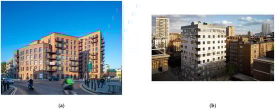
Figure 1.
Examples of multi-storey CLT residential buildings: (a) Dalston Works, London (Photo: Daniel Shearing) [7]; (b) Murray Grove, London [8].
Emerging architectural designs for high-rise CLT buildings, even skyscrapers (Tree Tower Toronto [9], 191–199 College Street [10]), bring great emphasis on the engineering challenges that need to be overcome [11], such as the seismic performance of CLT shear wall systems. The light-weight nature of timber contributes to lower seismic forces, while it also reduces buildings’ overturning resistance to lateral loads [12], which necessitates the development of high-performing connectors for the CLT shear wall panels or volumetrics.
Seismic-resistant design requires the ductile behaviour of certain components in structures, namely, steel parts in connections, since timber is not a ductile material and is prone to brittle tension, bending and shear failures [13]. Ductility can help the structures to: (1) dissipate energy in seismic events without losing the load-bearing capacity significantly, (2) allow for load redistribution within the structures to avoid further collapse and (3) ensure significant deformation without collapsing to warn the occupants [13]. Appropriate ductility also contributes to structures’ robustness, makes them resilient to unforeseen events without a total loss of functionality and is potentially capable of rapidly recovering their functionalities to a level similar to or even better than the pre-event level [14]. However, the conventional connection system used in CLT construction is limited by insufficient ductility compared to design expectations as well as brittle failure in timber or steel parts. To promote the development of CLT shear wall system, a series of new connection devices with enhanced performance were proposed in the recent literature, while only limited studies [15] have attempted to overview and holistically discuss the performance of these connections. This paper presents a state-of-the-art review of the existing literature on novel CLT connections and their performances to help researchers and engineers understand the level of research conducted for CLT connections. A systematic approach for summarising connections’ structural, constructional and manufacturing performance is presented, providing information for the future development of high-performing CLT connection systems, challenges and opportunities.
2. CLT Shear Wall System and Conventional Connections
2.1. CLT Shear Wall System
To design multi-storey CLT buildings in earthquake-prone areas, the seismic behaviours of CLT systems must be thoroughly investigated. One of the most comprehensive research projects to date is the project ‘Sistema Costruttivo Fiemme (SOFIE)’, which was tested dynamically using shake table experiments on three-storey and seven-storey full-scale CLT buildings [16,17,18] (Figure 2).
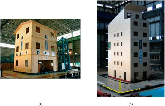
Figure 2.
(a) The three-storey [17] and (b) seven-storey CLT buildings [16] tested in the SOFIE project.
The full-scale tests proved the feasibility of multi-storey CLT construction in seismic regions, as both tested buildings were able to remain standing without significant permanent deformation and damages after experiencing the entire set of shakes, even when the near-collapse state was applied. In the tests with low peak ground acceleration (PGA), the buildings only experienced insignificant damage, as indicated by the reduced natural frequencies measured after each test. When higher PGA was applied, localised damage was recorded in the wall-to-floor connections, as shown in Figure 3, and they were consistently observed in the quasi-static monotonic and cyclic loading of one- or two-storey CLT buildings [19,20,21]. Though repairing interventions such as connector replacements and fasteners tightening were taken after every test, the structural stiffness cannot be fully restored [16].
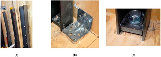
Figure 3.
Failure modes of a seven-storey CLT building in shake table testing: (a) out-of-plane bending of hold-down; (b) pulling-out of nails in angle brackets; (c) embedment of a connector [16].
When the CLT buildings are tested statically in the lateral directions, damages can also be observed in the CLT panels (Figure 4) at the later loading stage under large displacements, including the embedment of wall panels due to the panel rocking and cracking in the corner of the large openings of doors and windows due to the in-plane panel deformation [19,20,21]. It can therefore be concluded that the potential deformation modes of CLT buildings can be the in-plane deformation (shear, bending, axial) in the wall panels, the rigid rotation of wall panels and the deformation in wall-to-wall and wall-to-foundation connections [22]. In common practice, the yielding of metal fasteners in the wall-to-floor connections is considered as a favourable ductile failure mode in CLT buildings, as it provides better ductility and has lower risks of sudden strength loss, while it also damages the CLT elements.
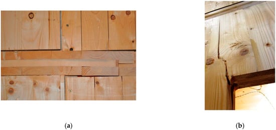
Figure 4.
Timber panels damage observed in the quasi-static test of CLT buildings under large displacement: (a) embedment of wall panels into floor panels that causes the debonding of timber planks; (b) cracking in the corner of a large opening [19].
In addition to the impact on the structural deformability, the connectors were also proven to have a significant influence on the kinematic behaviours of CLT shear walls. According to the vertical and horizontal movements of panels measured in quasi-static tests, the kinematic behaviours of CLT shear walls on each floor are the combination of sliding and rocking, the proportions of which are varied according to the arrangement and properties of connectors [19,23]. It was reported that when panel rocking dominates the kinematic behaviour, better ductility, energy dissipation and ultimate displacement can be achieved, along with the self-centring of wall panels under their self-weight, making it superior to the sliding behaviour, which resulted in a significant residual lateral displacement [24,25]. Therefore, to achieve energy-dissipative kinematic behaviour in CLT shear wall systems, connections are the essential factors to be considered in the design.
Consequently, both dynamic [16,18,26] and static [19,20,21,22,23,25,27] tests on CLT panelised systems indicated that structures made of CLT panels generally demonstrated a high strength and stiffness, with most of the deformation and energy dissipation being developed by the steel connections and the friction between timber panels, proving the feasibility of low-rise CLT construction in earthquake-prone regions. The governing role of steel connections in defining the overall structural performance necessitates the development of high-performing connections for reducing high accelerations of CLT buildings, providing better ductility, and enabling rocking and re-centring behaviours in the shear wall systems [16].
2.2. Conventional CLT Connections
In CLT buildings, two kinds of connections are commonly used: splice or nailed and screwed connections in wall-to-wall and floor-to-floor connections [28], and metal plate connectors (hold-downs and angle brackets) with dowel-type fasteners in wall-to-floor and wall-to-foundation connections [29]. As prescribed in EC8, the structural elements (timber) in timber buildings should remain elastically, while the dissipative zones should be located in the connections for resisting seismic actions. Therefore, the wall-to-floor and the wall-to-foundation connections are normally designed as energy dissipating devices in CLT structures, while the wall-to-wall and floor-to-floor connections are designed as non-ductile and should be over-strengthened. The metal plate connectors used in CLT structures are then the primary source of the ductility and mechanical performance that govern the delivery of secured structures [30].
2.2.1. Experimental Studies
The mechanical behaviours of hold-downs and angle brackets have been widely studied, with some drawbacks being commonly recognised despite their wide application in today’s CLT construction. The typical behaviour of metal plate connectors is the ‘strong plate–weak fastener’ behaviour [31], and one of their unique characteristics is the permanent damage fasteners introduced in timber. The deformed fasteners crush timber and create permanent cavities around them, which can lead to degraded stiffness and strength at load reversals, as well as reduced resistance and the delayed attainment of maximum strength during the cyclic process (Figure 5b,c). These features make the conventional connectors unpredictable and unrepairable, while they reduce the structure’s capacity and energy dissipation during the seismic event; meanwhile, they leave great residual displacements that reduce the structure’s resistance to aftershocks [16,28,32,33]. In addition, similar features can also be observed in the hysteresis loops of full-scale buildings (Figure 5a), which further demonstrate the impact of connection properties on the overall building’s performance.
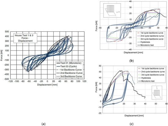
Figure 5.
Hysteresis loops and monotonic curve for (a) a two-storey full-scale CLT building [19], and the (b) angle brackets and (c) hold-downs that are used in the building [24].
In addition to timber damage, both angle brackets and hold-downs are characterised by a high stiffness but an insufficient ductility [24,34], belonging to the L-low ductility class (2 < < 4) or M-medium ductility class (4 < < 6), as prescribed in EC8 [35], in their primary directions. As dissipative timber connections are required to achieve the ductility classes M-medium or H-high (6 < ), increasing the number of connectors and using small-diameter fasteners are the recommended methods of designing ductile timber structures with conventional connections [35,36]. The large number of connectors and fasteners can lead to time-consuming on-site fastening work with hard-to-verify assembly quality [37] and can also limit the potential of fully reusing timber components, as the removal of nails and screws can be labour-intensive and further damage the structural material [38]. Additionally, small-diameter fasteners can introduce high stress in timber and pinch through the fibres before the capacity of timber is fully developed, causing brittle failure with a sudden reduction in connection strength and large residual displacement, even after the removal of the external loading.
2.2.2. Analytical Models and Design Rules
As a new structural material, specific design codes or guidance for CLT have not yet been developed [39]. The general rules for timber buildings in EC5 and EC8 or information in the relevant literature are applied when designing CLT structures, though they are not fully applicable. Previous comparative studies between analytical and experimental results [24,34,36] indicated the conservative approach to strength prediction (lower than 80% of the tested results) and the significant stiffness overestimation (up to nine times higher) of the existing analytical models of timber connections [24,40].
The prediction errors can be attributed to several factors of timber connections. The bearing capacity of conventional timber connections is defined by the combinations of the embedment strength, the sensitivity to splitting, the connection configurations as well as the variation of the fastener types in connections [41]. Due to its heterogeneity, timber behaves differently in different directions and may have inherent defects such as large knots, resin pockets and bark inclusions [3]. Therefore, making the capacity dependent on the timber with dispersive properties as a natural material [42] may lead to unpredictable connection behaviours as well as considerable variations between specimens [36], especially when the damage progression mechanism within timber is not well understood, which also limits the development of accurate modelling methods.
To ensure the full activation of all ductile elements and avoid plasticisation in non-ductile zones [43], as required in EC8 [35], the overstrength method that was developed by Jorissen and Fragiacomo (Equation (1)) [13] is widely used on both building and connection levels in timber structure design. This can also lead to errors in the analytical predictions. At the building level, all timber elements and connections in non-dissipative zones (e.g., wall-to-wall and floor-to-floor connections) are strengthened to avoid plasticisation. At the connection level, timber elements are strengthened to ensure the development of cyclic yielding in fasteners [44]. In this method, the introduction of the overstrength factor in the design strength of brittle elements () is for eliminating the impacts of all possible factors that may lead to an unexpected stronger capacity in ductile elements ().
However, the embedment strength calculated with Johansen’s theory in EC5 [45] can be significantly inaccurate due to the greater scattering of timber material properties compared to the steel material [46], and specific overstrength factors for different connections are not yet in the standards [39]. The estimated overstrength factor could therefore be insufficient and limit the attainment of the overstrength effect. Thus, in addition to the overstrength method, common strategies in EC5 for avoiding brittle failure in timber connections introduce prescriptive safeguards in connection configuration design, such as minimum spacings, a minimum number, slenderness ratios and edge distances of fasteners and the effective number of fasteners [36]. However, the conventional steel connectors may experience brittle failure even with these safeguarding factors being properly applied, as recorded in an experimental study [47].
Furthermore, the capacities of brittle elements (timber) and ductile elements (fasteners) are considered independently in the overstrength method, which, however, is unrealistic because of the simultaneous deformation in timber, steel plates and fasteners in conventional plate connections. Desirable fasteners yielding (ductile behaviour) normally appears, along with other failure modes such as timber crushing or splitting (brittle behaviour), steel plate fracture (brittle behaviour) or bending (ductile behaviour) as well as nail breakage and pulling-out (brittle behaviour) [29,48,49,50,51] (Figure 6). The primary failure modes varied according to the different connection factors, such as fastener types, arrangements and geometry, timber properties, loading directions, connection locations as well as connector configurations. The interaction between these factors is still unknown, making it difficult to predict the primary failure mode of connections using existing analytical models, in which only timber crushing and fastener yielding are considered along with the assumption of rigid steel plates. The ignorance of the composite effect and the rigid plate assumption taken in current analytical models could lead to significant estimation errors, especially for connections with small steel plate thicknesses, as they overlook the deformation contribution of steel elements [24,34]. For example, it is suggested in EC5 that the stiffness calculated for steel-to-timber connections should be doubled up to account for the strengthening of the steel plate, which was proven to lead to greatly higher connections stiffness [40,52]. The inaccurate representation of connection stiffness, which is especially crucial to the global stiffness of CLT shear wall systems, as discussed above, can lead to significant errors in the estimation of the principal elastic vibration period in seismic design, as proven in a numerical parametric study [53]. When all brittle failure modes are considered, some newly proposed analytical models [54,55,56] showed better agreement with the test results and provided clearer identifications of the related failure modes [36,57], indicating the need for further improving the design guideline of the conventional metal plate connections.
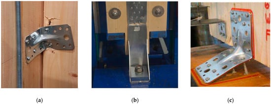
Figure 6.
Different kinds of failure modes in timber plate connections: (a) cutting-through of fasteners in timber; (b) breakage in a metal connector; (c) pulling-out of fasteners [34,52].
2.3. Overview Conclusion
Despite the wide application, the local- and macro-scale testing on conventional timber connections revealed the insufficient mechanical performance, the risk of brittle failure and the performance stability of them being applied in large CLT construction. The comparison studies between the experimental and analytical results proved that the performance of timber connections is not yet fully understood and standardised, which can lead to risks of unforeseeable connection behaviours and difficulties in structural design. Furthermore, the lack of design guidance, particularly for the identification of suitable, ductile failure mechanisms, further increases the difficulties of designing ductile timber connections, which is an important issue in seismic design. This is the main barrier for the slow adoption of timber structures in the construction sector and the general hesitance perceived despite the desire of architects and engineers to use this biomaterial more widely.
3. Innovative Connections for CLT Shear Walls
3.1. Innovative Connections for CLT Shear Wall Systems
To improve the seismic behaviours of CLT structures and address the identified limitations in conventional timber connections, a series of new connectors have been recently proposed and are summarised here (Table 1) for the ease of comparison and discussion.

Table 1.
Innovative connectors for CLT shear wall systems.
Complementary to the introduction of the innovative connectors, the experimental studies carried out to prove the mechanical performance of these CLT connectors are summarised in Table 2.
Table 2.
Comparison of the experimental results for the novel connections.
3.2. Performance Evaluation for Novel CLT Connectors
According to Table 1, additional two- or three-dimensional steel connectors are introduced in most of the new CLT connector designs to replace conventional steel plates. Apart from the improved mechanical performance, all novel connectors have their own unique features for addressing the aforementioned limitations of conventional connectors. It is therefore difficult to directly evaluate or compare the connectors’ performance when their design philosophies are somewhat—and, in certain cases, completely—different. In addition to the necessary structural needs, the manufacturing and constructional performance of connectors define the efficiency and the overall cost of CLT construction and should therefore also be well considered in the design of CLT connectors to promote practical applications. Multi-attribute performance evaluation systems for steel modular connectors were previously proposed by Srisangeerthanan et al. [84] and Corfar & Tsavdaridis [85], with comprehensive considerations and explanations regarding the structural performance, manufacturability and constructability being included. Some evaluating criteria are herein adopted and tailored based on the unique characteristics of CLT construction to elucidate and enhance the discussions of such connections’ performances.
3.2.1. Structural Performance
From the structural performance perspective, panelised structures such as CLT shear wall systems require connectors to have adequate shear and tension capacity. While all new connectors can achieve adequate resistance in their primary working direction, some connectors (CLT-C4-8, 11, 13, 16) are designed to work in only one direction, and their capacities in the secondary direction are limited. This may help establish a clearer relationship between the connection properties and the shear wall performance with no coupling behaviours between the shear and tension, while a limited capacity and undesirable failure modes in the secondary working direction may lead to unexpected failure (for example, the buckling failure observed in Table 2 for CLT-C13 under compression) without achieving the full capacity. Therefore, having an adequate capacity in both working directions would be desirable, and the strength in the secondary working direction can be treated as an additional reinforcement to structures.
Contrary to the “strong plate–weak fasteners” concept for conventional connections, most of the newly proposed connectors (CLT-C1, 4–14) achieve strong fasteners–weak metal connector behaviours along with the much-improved ductility (Class H) (Table 2), which is achieved by adopting big-diameter fasteners for a higher yielding strength in the timber–fastener connection than that in metal connectors. In this way, the source of inelastic deformation switches from the yielding of fasteners and the crushing of timber, as in conventional connections, to the more ductile bending (CLT-C1, 8–10 and 12) or sliding (CLT-C4-7) of the steel connectors (Table 2). Owing to the well-standardised homogeneous properties of steel material, the controlled deformation of metal elements can provide an improved ductility and predictable mechanical performance; meanwhile, it can eliminate the impact of the inherent defects in the connected timber elements. The reduced deformation in fasteners can also help eliminate damage in timber and avoid brittle failure in structural elements. The common application of the so-called ‘damage avoidance philosophy’ in the novel connector design reflects the widely recognised concerns regarding timber damage with regard to conventional connections.
Additionally, the better ductility in those connectors (Table 2; CLT-C4-8, 10, 11 and 13) designed as the alternatives to conventional hold-downs connections can promote rocking behaviour for improved energy dissipation in CLT shear wall systems, which also satisfies the increasing demands in the uplift resistance and energy dissipation of large timber construction. To further enhance the performance of re-centring during the rocking of panels, some new connectors (CLT-C4, 5, 7, 11) adopt special elements such as springs and reversible plastic extrusion to achieve a higher stiffness in the unloading process with a much plumper hysteresis curve.
3.2.2. Constructability
In addition to the mechanical performance, construction requirements should also be carefully considered in the connector design stage, as they determine the ease, speed and quality of CLT construction. The ideal CLT connections for efficient construction should be compact, easy to install, with reduced manual efforts, able to address tolerance requirements and demountable to enable disassembly and reuse in the future.
When designing connectors for constructional performance, some specific factors should be considered. First, connectors should provide easy onsite assembly methods of structural elements for an increased construction efficiency and lower construction costs in the context of rapidly increasing labour costs. Most of the new connections are still using onsite screws fastening, which is similar to conventional steel plate connectors. CLT-C15 and 16, on the other hand, employ an interlocking technique that requires no fastners onsite, which is a connecting method used in ancient timber structures and is readopted in modern connection design to promote more efficient assembly in construction.
Secondly, the fasteners that joint the connectors and structural elements should be carefully chosen, as the fastening of screws in conventional connectors takes up most of the workload. Different from the small-diameter fasteners used in conventional plate connections, which are labour-intensive to install, big-diameter screws or bolts are adopted more frequently in novel connectors (CLT-C1, 4–7 and 13). The adoption of bigger fasteners can increase the capacity of the timber-to-fastener connection with a reduced fastener number for the improved construction efficiency as well as the realisation of the ‘strong fasteners–weak metal connector’ and ‘damage avoidance’ philosophies. Connectors designed with these philosophies, especially those using big-diameter bolts and dowels (CLT-C1, 4, 5, 7–11 and 13), can be repaired or replaced while introducing less damage in the timber, which is ideal for facilitating structure maintenance and structural material recycling or reuse, especially for those that are located at the exterior surface of CLT panels and require no panel modification for the fitting of connectors (CLT-C1, 4, 8 and 13). Some connectors (CLT-C2, 5, 7, 9, 10 and 12) require profiling (cutting, drilling) on timber for connector placement, which can cause a cross-sectional loss of the structural elements and, thus, an increased workload and cost. In addition to the conventional fixing method of mechanical fasteners, chemical adhesive can be found in some new connectors (CLT-C9 and 14). Though a very high stiffness can be achieved in these connectors, the adhesive formation process could be problematic for onsite installation, as it may be affected by numerous factors such as weather and site conditions. Third, connectors should be able to accommodate considerable levels of construction tolerances for unexpected onsite adjustments. Connectors (CLT-C2, 10 and 15–16) that have a complex profile and require accurate onsite operation may be difficult to assemble onsite when unexpected construction errors happen, while those (CLT-C1, 4, 6, 8, 13 and 14) attached at the exterior surface of CLT panels can be easily adaptable to project and construction changes.
For further achieving a better installation quality and efficiency with a reduced onsite workload, the connectors CLT-C2, 15 and 16 are designed as prefabricated connectors. These connectors can be accurately pre-assembled and installed onto the timber in a controlled environment, which is especially beneficial for those that require special tooling. For prefabricated connectors, it is crucial to have a suitable design for transport vehicles and to be able to use as a temporary support system during panel lifting, such as the X-RAD connector (CLT-C2) (Figure 7b). It can be treated as an additional constructional benefit, as traditional panel lifting involves hole drilling and filling on panels for placing lift devices (Figure 7a). For CLT-C15 and 16, which adopt the interlocking technique, structural elements can be self-locked onsite with less effort, and they can be disassembled without the need for demolition, which means that the structures are adaptable to potential environmental or functional changes.
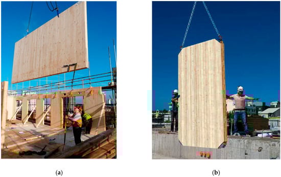
Figure 7.
Panel lifting with (a) the conventional method [86] and (b) novel connectors (CLT-C2) [60].
3.2.3. Manufacturability
The manufacturability of connectors governs the speed and quality of mass production; that can be considered from the connector complexity (geometry, component number, material, processing procedures). Connection parts that can be easily fabricated using conventional manufacturing methods can contribute to much faster commercialisation and significantly lower construction costs. For those that are more geometrically complex, special manufacturing methods such as 3D printing are required, which can significantly increase the manufacturing cost. On a positive note, the supply chain issue can be solved, especially when quick replacement is required after the damage of a connection component. All novel connections listed in Table 1 can be fabricated using conventional manufacturing methods. The planar connectors such as CLT-C1, 8, 9, 12 and 14 are the most mass-producible; they can be simply cut from steel sheets. For those 3D connectors, multi-process manufacturing may be required, with significantly higher costs. For example, the cap and centre plates of CLT-C5 can be sawn from a merchant flat bar and then milled to achieve the toothing shape on the surface. Alternatively, they can be produced from a custom rolled special section in 6 m lengths and then be sawn, drilled and slotted, which, however, would require a minimum ordering of 100 tonnes, according to the UK steel manufacturer SC4. For CLT-C13, different components require different manufacturing methods. The wall support of it can be produced from either a stock PFC or a press braked channel, while the foundation support should be produced from either a tee section or fabricated from the profiled/drilled plate. The steel sleeve in the middle also requires separate manufacturing from a profiled and formed plate before being integrated with other components.
As some of the new connectors have more than two components (CLT-C4, 5, 7, 10, 11 and 13), careful assembly (installation) processes in factories or onsite will be required, which also governs the cost and efficiency of production. Moreover, in some cases, special operations are required during the assembly process (e.g., welding in CLT-C10 and 13), which can further reduce the production efficiency and increase the cost. In addition, tolerances in the assembly processes should also be carefully considered during the connection design phase. Considering the accuracy of conventional manufacturing methods, a 1–2 mm tolerance between components should be achievable to avoid the fitting difficulties caused by dimensional errors.
4. Novel Proposed Demountable Connection System for Multi-Storey CLT Buildings with Damage Avoidance Capacity
Based on the connector performance discussions, a novel prefabricated connection system that provides new connecting solutions for CLT modular (panelised and volumetric) construction by interlocking was proposed [87] (Figure 8), aiming to achieve high-quality CLT construction with reduced time, labour and waste. With the interlocking techniques employed in this connection system, structural elements can be easily and accurately assembled onsite by stacking (Figure 8a) or sliding (Figure 8c), without the need for onsite screw fastening. The sliding connector in the system can also act as a guiding device during the assembly process, contributing to the accurate alignment of the structural elements.
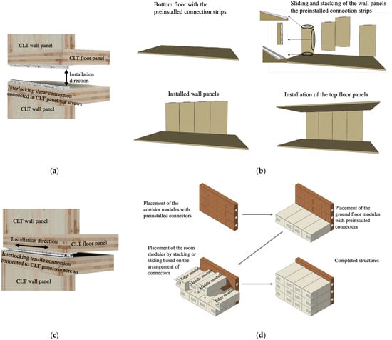
Figure 8.
Novel interlocking connectors for CLT modular construction: (a) shear stacking connector and (c) tensile sliding connector, and their application in (b) CLT panelised structures and (d) CLT volumetric structures.
In addition to the advanced connecting method, this connection system also offers a damage avoidance effect with the specially designed 3D metal connectors. In both tensile and shear connectors, complex geometries are applied on the metal components to achieve a lower resistance than the yielding capacity of the surrounding fasteners, making them the weakest elements in the connection system that always fail first (strong fasteners–weak metal connector philosophy), when all the other components remain intact (act elastically). In this way, chunky fasteners are used to reinforce the connection between the timber and fasteners and avoid plasticisation, which reduces the reliance on small-diameter metal fasteners, as in conventional connectors. Being designed as a continuous strip connector, the proposed system can provide continuous support along the edge of structural elements instead of the conventional discrete point-to-point connecting methods.
Considering the higher dimensional accuracy for connector fitting and the high cost of moulding conventional manufacturing methods, the prototypes of this new connection were 3D-printed integrally with a 1 mm tolerance for the fitting of connectors. The mass production of this kind of complex 3D connector is potentially achievable with the conventional method but with a more complex process. For the male connector in the shear connection, the cantilevering curving element and the central support should be produced separately from the 3D-formed strips and then welded to the drilled base plate. For the tensile connectors that have a continuous section along the length, the production could be easier from a special hot rolled section and then sawn to the length.
This connection system employed different advanced technologies in timber connection design, such as fastener-free assembly and damage avoidance philosophy, and it requires no profiling on timber panels for the connector placement; it is therefore easily adjustable for different projects by simply varying the length of the connection strips. With an automotive lifting system and improved manufacturing methods, this connection system can be a promising solution for CLT modular construction, with effortless, more accurate onsite assembly, reduced construction waste production and ful reusability in both structural elements and connectors.
5. Conclusions
This paper summarises the design features of 18 recently developed novel steel connections newly proposed as reinforcing methods for CLT shear wall systems. The structural, constructional and manufactural performances of these connections were discussed to determine their viability in addressing the identified disadvantages of achieving rapidly deployable and reusable CLT modular construction. A series of common strategies for achieving a more stable performance, improved ductility and reduced installation effort in connectors can be identified from the summarised connector designs. In terms of structural performance, much improved ductility can be observed in the new connectors with the damage avoidance philosophy. Some of them can help achieve a better dynamic performance in structures by promoting the rocking and re-centring of panels. The common adoption of large-diameter dowel-type fasteners is expected to further improve the CLT construction efficiency, and new ways of joining structural elements, such as interlocking and chemical adhesives, are explored in connectors. In addition to the structural and constructional performance, the potential of mass production should also be well considered in the design of new connectors. All these design tendencies reveal the growing interest in high-rise CLT structures and the increasing concerns regarding their seismic performance, construction efficiency and reusability.
6. Future Perspectives
The design of future CLT connectors requires comprehensive considerations of the structural, constructional and manufactural aspects. The connection design that has simple but efficient geometries and can be easily fixed to modular elements is urgently needed in current CLT modular construction, ensuring the fast realisation and commercialisation of the connection concepts for practical applications. For future large CLT buildings with more complex structures and increased functional requirements, 3D connectors with multiple functionalities, such as damage-free effects, optimised energy dissipation, re-entering capacity, interlocking and demountability, are believed to be the more promising solutions, the adoption of which is now a growing trend in steel modular construction. These functionalities not only contribute to a better structural performance but also improve the efficiency and adaptability in construction. Considering the great modifiability of timber, an adaptable connection design can promote the rearrangement, recycling and reuse of material during or after the service life of buildings, extending the life cycle of material and further improving the sustainability of timber construction. Advanced manufacturing techniques such as 3D printing can be used to produce such complex connector components or even to provide customised solutions for specific projects or structural requirements [88]. The incorporation of such innovative functionalities and manufacturing techniques can also foster the achievement of high-performing CLT connectors as well as automated CLT construction.
Despite the improved mechanical behaviours of the innovative CLT connectors observed in experimental and numerical studies at the micro- and meso-scale levels, the testing of these connectors in full-scale CLT buildings has not yet been performed. Full-scale global tests are necessary to access the effectiveness of these solutions in improving the structural performance and overall stability under complex loading conditions such as wind, earthquake and blast loads, as well as to validate accurate and reliable numerical local and global models. Further experimental investigations are therefore necessary for the development of detailed guidance on numerical analysis for assessing CLT building performance, which can promote the use of new connector products in CLT construction.
The new generation of Eurocode 8—the timber part—will introduce an updated list of timber-based structural systems with clear definitions of dissipative and non-dissipative zones in structures, which are needed for the newly introduced capacity design rules and overstrength factors for each type of structural system. CLT shear wall systems that are not present in the current version will be included as an independent timber structural system in the Standards [44]. Further, a new procedure for the application of non-linear static (pushover) analysis will be provided [11]. In this context, the rapid development of CLT panelised construction is foreseeable in the near future, necessitating the proposal of connectors that can help achieve rapidly deployable and reusable structures with an adequate structural performance. Therefore, all three aspects (structure, construction and manufacture) should be considered comprehensively in the design of future CLT connectors in order to achieve not only a better efficiency and lower cost in CLT construction but also easier standardisation and commercialisation.
Author Contributions
Writing—original draft preparation, data curation: Z.L.; draft review, general management, supervision: K.D.T. All authors have read and agreed to the published version of the manuscript.
Funding
The authors and the 3DMBC (https://3dmbc.com (accessed on 15 October 2022)) group members would like to acknowledge the Royal Academy of Engineering and The Leverhulme Trust funds [LTSRF1819_15_40] as well as The Henry Lester Trust funds for their financial support in 3D printing the connection specimens.
Data Availability Statement
Data sharing not applicable.
Acknowledgments
The authors would like to thank Marco Pagliarin, the Design Manager of Hybrid Structures (William Hare), for his very valuable and continuous technical support. His experience and expertise were instrumental in completing this review work. The authors would also like to thank Shay Eddy, the Commercial and Technical Director of SC4, for his technical support with regard to the fabrication of certain complex connection systems.
Conflicts of Interest
The author declare no conflict of interest.
References
- Karacabeyli, E.; Gagnon, S. Canadian CLT Handbook, 1st ed.; FPInnovations: Pointe-Claire, QC, Canada, 2019; Volume 1. [Google Scholar]
- Hassanieh, A.; Valipour, H.; Bradford, M. Composite connections between CLT slab and steel beam: Experiments and empirical models. J. Constr. Steel Res. 2017, 138, 823–836. [Google Scholar] [CrossRef]
- Kurzinski, S.; Crovella, P.; Kremer, P. Overview of Cross-Laminated Timber (CLT) and Timber Structure Standards Across the World. Mass Timber Constr. J. 2022, 5, 1–13. [Google Scholar]
- Guo, H.; Liu, Y.; Meng, Y.; Huang, H.; Sun, C.; Shao, Y. A Comparison of the Energy Saving and Carbon Reduction Performance between Reinforced Concrete and Cross-Laminated Timber Structures in Residential Buildings in the Severe Cold Region of China. Sustainability 2017, 9, 1426. [Google Scholar] [CrossRef]
- Liu, Y.; Guo, H.; Sun, C.; Chang, W. Assessing Cross Laminated Timber (CLT) as an Alternative Material for Mid-Rise Residential Buildings in Cold Regions in China—A Life-Cycle Assessment Approach. Sustainability 2016, 8, 1047. [Google Scholar] [CrossRef]
- Svatoš-Ražnjević, H.; Orozco, L.; Menges, A. Advanced Timber Construction Industry: A Review of 350 Multi-Storey Timber Projects from 2000–2021. Buildings 2022, 12, 404. [Google Scholar] [CrossRef]
- Dehart, C. This is the World’s Largest CLT Building—And You’d Never Know It. 2018. Available online: https://gbdmagazine.com/worlds-largest-clt/ (accessed on 1 September 2022).
- WATTS GROVE. Ground Breaking Modular Housing. Available online: https://waughthistleton.com/watts-grove/ (accessed on 13 October 2022).
- Howarth, D. Penda Proposes Toronto Tree Tower Built from Cross-Laminated Timber Modules. 2017. Available online: https://www.dezeen.com/2017/08/02/toronto-tree-tower-penda-cross-laminated-timber-construction/ (accessed on 1 September 2022).
- Dreith, B. Icon Architects Unveils Design for Tallest Mass-Timber Building in North America. 2022. Available online: https://www.dezeen.com/2022/07/22/icon-architecture-tallest-mass-timber-building-north-america/ (accessed on 1 September 2022).
- Stepinac, M.; Šušteršič, I.; Gavric, I.; Rajčić, V. Seismic Design of Timber Buildings: Highlighted Challenges and Future Trends. Appl. Sci. 2020, 10, 1380. [Google Scholar] [CrossRef]
- Zhang, X.; Popovski, M.; Tannert, T. High-capacity hold-down for mass-timber buildings. Constr. Build. Mater. 2018, 164, 688–703. [Google Scholar] [CrossRef]
- Jorissen, A.; Fragiacomo, M. General notes on ductility in timber structures. Eng. Struct. 2011, 33, 2987–2997. [Google Scholar] [CrossRef]
- Soerensen, J.D. Framework for robustness assessment of timber structures. Eng. Struct. 2011, 33, 3087–3092. [Google Scholar] [CrossRef]
- Tannert, T.; Loss, C. Contemporary and Novel Hold-Down Solutions for Mass Timber Shear Walls. Buildings 2022, 12, 202. [Google Scholar] [CrossRef]
- Ceccotti, A.; Sandhaas, C.; Okabe, M.; Yasumura, M.; Minowa, C.; Kwai, N. SOFIE project-3D shaking table test on a seven-storey full-scale cross-laminated timber building. Earthq. Eng. Struct. Dyn. 2013, 42, 2003–2021. [Google Scholar] [CrossRef]
- Ceccotti, A. New Technologies for Construction of Medium-Rise Buildings in Seismic Regions: The XLAM Case. Struct. Eng. Int. J. Int. Assoc. Bridge Struct. Eng. 2008, 18, 156–165. [Google Scholar] [CrossRef]
- Carmen Sandhaas, A.C. Earthquake resistance of multi-storey massive timber buildings. In 2nd Forum Holzbau Beaunue; FORUM HOLZBAU: Biel, Switzerland, 2012. [Google Scholar]
- Popovski, M.; Gavric, I. Performance of a 2-Story CLT House Subjected to Lateral Loads. J. Struct. Eng. 2016, 142, E4015006. [Google Scholar] [CrossRef]
- Yasumura, M.; Kobayashi, K.; Okabe Miyake, T. Full-Scale Tests and Numerical Analysis of Low-Rise CLT Structures under Lateral Loading. J. Struct. Eng. 2016, 142, E4015007. [Google Scholar] [CrossRef]
- Matos, F.T.; Branco, J.M.; Rocha, P.; DemSchner, T.; Lourenço, P.B. Quasi-static tests on a two-story CLT building. Eng. Struct. 2019, 201, 109806. [Google Scholar] [CrossRef]
- Pozza, L.; Roberto, S.; Davide, T.; Pinna, M.; Polastri, A.; Beroni, P. Experimental and Numerical Analyses of New Massive Wooden Shear-Wall Systems. Buildings 2014, 4, 355–374. [Google Scholar] [CrossRef]
- Popovski, M.; Gavric, I.; Schneider, J. Performance of two-storey CLT house subjected to lateral loads. In Proceedings of the World Conference on Timber Engineering, Quebec City, QC, Canada, 14 August 2014. [Google Scholar]
- Gavric, I.; Fragiacomo, M.; Ceccotti, A. Cyclic behaviour of typical metal connectors for cross-laminated (CLT) structures. Mater. Struct. 2015, 48, 1841–1857. [Google Scholar] [CrossRef]
- Gavrić, I.; Fragiacomo, M.; Ceccotti, A. Capacity seismic design of X-LAM wall systems based on connection mechanical properties. In Proceedings of the 46th CIB-W18 Meeting, Vancouver, BC, Canada, 26–29 August 2013. [Google Scholar]
- Hristovski, V.; Dujic, B.; Stojmanovska, M.; Mircevska, V. Full-Scale Shaking-Table Tests of XLam Panel Systems and Numerical Verification: Specimen 1. J. Struct. Eng. 2013, 139, 2010–2018. [Google Scholar] [CrossRef]
- Hughes, C.; McPolinl, D.; McGerick, P.; McCrum, D. Behaviour of cross-laminated timber wall systems under monotonic lateral loading. J. Struct. Integr. Maint. 2019, 4, 153–161. [Google Scholar] [CrossRef]
- Gavric, I.; Fragiacomo, M.; Ceccotti, A. Cyclic behavior of typical screwed connections for cross-laminated (CLT) structures. Eur. J. Wood Wood Prod. 2015, 73, 179–191. [Google Scholar] [CrossRef]
- Tomasi, R.; Smith, I. Experimental Characterization of Monotonic and Cyclic Loading Responses of CLT Panel-To-Foundation Angle Bracket Connections. J. Mater. Civ. Eng. 2015, 27, 04014189. [Google Scholar] [CrossRef]
- Sandoli, A.; D’Ambra, C.; Ceraldi, C.; Calderoni, B.; Prota, A. Sustainable Cross-Laminated Timber Structures in a Seismic Area: Overview and Future Trends. Appl. Sci. 2021, 11, 2078. [Google Scholar] [CrossRef]
- Latour, M.; Rizzano, G. Cyclic Behavior and Modeling of a Dissipative Connector for Cross-Laminated Timber Panel Buildings. J. Earthq. Eng. JEE 2015, 19, 137–171. [Google Scholar] [CrossRef]
- Chan, N.; Hashemi, A.; Zarnani, P.; Quenneville, P. Pinching-Free Connector for Timber Structures. J. Struct. Eng. 2021, 147, 4021036. [Google Scholar] [CrossRef]
- Aloisio, A.; Pelliciari, M.; Berami, A.V.; Aloggio, R.; Briseghella, B.; Fragiaomo, M. Effect of pinching on structural resilience: Performance of reinforced concrete and timber structures under repeated cycles. Struct. Infrastruct. Eng. 2022, 1–17, ahead-of-print. [Google Scholar] [CrossRef]
- O’Ceallaigh, C.; Harte, A.M. The elastic and ductile behaviour of CLT wall-floor connections and the influence of fastener length. Eng. Struct. 2019, 189, 319–331. [Google Scholar] [CrossRef]
- EN 1998-1; Eurocode 8-Design of Structures for Earthquake Resistance-Part 1: General Rules, Seismic Actions and Rules for Buildings. European Committee for Standardisation: Brussels, Belgium, 2004.
- Yurrita, M.; Cabrero, J.M. On the need of distinguishing ductile and brittle failure modes in timber connections with dowel-type fasteners. Eng. Struct. 2021, 242, 112496. [Google Scholar] [CrossRef]
- Polastri, A.; Giongo, I.; Piazza, M. An Innovative Connection System for Cross-Laminated Timber Structures. Struct. Eng. Int. J. Int. Assoc. Bridge Struct. Eng. 2017, 27, 502–511. [Google Scholar] [CrossRef]
- Iacovidou, E.; Purnell, P. Mining the physical infrastructure: Opportunities, barriers and interventions in promoting structural components reuse. Sci. Total Environ. 2016, 557, 791–807. [Google Scholar] [CrossRef]
- Fragiacomo, M.; Dujic, B.; Sustersic, I. Elastic and ductile design of multi-storey crosslam massive wooden buildings under seismic actions. Eng. Struct. 2011, 33, 3043–3053. [Google Scholar] [CrossRef]
- Izzi, M.; Flatscher, G.; Fragiaomo, M.; Schickofer, G. Experimental investigations and design provisions of steel-to-timber joints with annular-ringed shank nails for Cross-Laminated Timber structures. Constr. Build. Mater. 2016, 122, 446–457. [Google Scholar] [CrossRef]
- Jorissen, A.J.M. Double Shear Timber Connections with Dowel Type Fasteners. Doctoral Thesis, Delft University of Technology, Delft, The Netherlands, 1998. [Google Scholar]
- Schickhofer, G.; Brandner, R.; Bauer, H. Introduction to CLT, product properties, strength classes. In Proceedings of the Joint Conference of COST Actions FP1402 & FP1404, Cross Laminated Timber-a Competitive Wood Product for Visionary and Fire Safe Buildings, Stockholm, Sweden, 10 March 2016. [Google Scholar]
- Izzi, M.; Casagrande, D.; Bezzi, S.; Pasca, D.; Follesa, M.; Tomasi, R. Seismic behaviour of Cross-Laminated Timber structures: A state-of-the-art review. Eng. Struct. 2018, 170, 42–52. [Google Scholar] [CrossRef]
- Follesa, M.; Fragiacomo, M.; Casagrande, D.; Piazza, M.; Vassallo, D.; Canetti, D.; Rossi, S. The new provisions for the seismic design of timber buildings in Europe. Eng. Struct. 2018, 168, 736–747. [Google Scholar] [CrossRef]
- EN 1995-1-1; Eurocode 5-Design of Timber Structures-Part 1-1: General Common Rules and Rules for Buildings. European Committee for Standardisation: Brussels, Belgium, 2004.
- Trutalli, D.; Marchi, L.; Scotta, R.; Pozza, L. Capacity design of traditional and innovative ductile connections for earthquake-resistant CLT structures. Bull. Earthq. Eng. 2019, 17, 2115–2136. [Google Scholar] [CrossRef]
- Mahlknecht, U.; Brandner, R. Block shear failure mechanism of axially-loaded groups of screws. Eng. Struct. 2019, 183, 220–242. [Google Scholar] [CrossRef]
- Pozza, L.; Saetta, A.; Savoia, M.; Talledo, D. Angle bracket connections for CLT structures: Experimental characterization and numerical modelling. Constr. Build. Mater. 2018, 191, 95–113. [Google Scholar] [CrossRef]
- Liu, J.; Lam, F. Experimental test of coupling effect on CLT angle bracket connections. Eng. Struct. 2018, 171, 862–873. [Google Scholar] [CrossRef]
- Marchi, L. Innovative Connection Systems For Timber Structures. Doctoral Thesis, The University of Padua, Padua, Italy, 2018. [Google Scholar]
- Schneider, J.; Karacabeyli, E.; Popovski, M.; Stiemer, S.F.; Tesfamariam, S. Damage Assessment of Connections Used in Cross-Laminated Timber Subject to Cyclic Loads. J. Perform. Constr. Facil. 2014, 28, 4014008. [Google Scholar] [CrossRef]
- Izzi, M.; Polastri, A.; Fragiacomo, M. Modelling the mechanical behaviour of typical wall-to-floor connection systems for cross-laminated timber structures. Eng. Struct. 2018, 162, 270–282. [Google Scholar] [CrossRef]
- Polastri, A.N.; Pozza, L. Proposal for a Standardized Design and Modeling Procedure of Tall clt buildings. Int. J. Qual. Res. 2016, 10, 607–624. [Google Scholar]
- Yurrita, M.; Cabrero, J.M. New design model for brittle failure in the parallel-to-grain direction of timber connections with large diameter fasteners. Eng. Struct. 2020, 217, 110557. [Google Scholar] [CrossRef]
- Zarnani, P.; Quenneville, P. New design approach for controlling brittle failure modes of small-dowel-type connections in Cross-laminated Timber (CLT). Constr. Build. Mater. 2015, 100, 172–182. [Google Scholar] [CrossRef]
- Hanhijärvi, A.; Kevarinmäki, A. Design Method against Timber Failure Mechanisms of Dowelled Steel-to-Timber Connections; CIB-W18 Timber Structures: Bled, Slovenia, 2007; p. 40-7-3. [Google Scholar]
- Yurrita, M.; Cabrero, J.M.; Quenneville, P. Brittle failure in the parallel-to-grain direction of multiple shear softwood timber connections with slotted-in steel plates and dowel-type fasteners. Constr. Build. Mater. 2019, 216, 296–313. [Google Scholar] [CrossRef]
- Marchi, L.; Trutalli, D.; Scotta, R.; Pozza, L. Nnumerical simulation of the coupled Tension-Shear response of an innovative dissapative connection for CLT buildings. In Proceedings of the 6th ECCOMAS Thematic Conference on Computational Methods in Structural Dynamics and Earthquake Engineering, Rhodes Island, Greece, 15–17 June 2017; pp. 247–254. [Google Scholar]
- Polastri, A.; Giongo, I.; Angeli, A.; Brandner, R. Mechanical characterization of a pre-fabricated connection system for cross laminated timber structures in seismic regions. Eng. Struct. 2018, 167, 705–715. [Google Scholar] [CrossRef]
- Rothoblaas. X-RAD: X-RAD Connection System. Available online: https://www.rothoblaas.com/products/fastening/brackets-and-plates/x-rad/x-rad (accessed on 6 July 2022).
- Kraler, A.; Kögl, J.; Maderebner, R.; Flach, M. SHERPA-CLT-Connector for Cross Laminated Timber (CLT) Elements. 2013. In Proceedings of the 13th World Conference on Timber Engineering (WCTE2014), Quebec City, QC, Canada, 14 August 2014. [Google Scholar]
- Shao, F.; Wang, Y.; Lian, W.; Benjeddou, O. Experimental and numerical investigation on withdrawal connectors usage for lateral resistance of timber shear walls structure. J. Build. Eng. 2021, 44, 103266. [Google Scholar] [CrossRef]
- Hashemi, A.; Zarnani, P.; Masoudnia, R.; Quenneville, P. Experimental Testing of Rocking Cross-Laminated Timber Walls with Resilient Slip Friction Joints. J. Struct. Eng. 2018, 144, 4017180. [Google Scholar] [CrossRef]
- Hashemi, A.; Zarnani, P.; Quenneville, P. Earthquake resistant timber panelised structures with resilient connections. Structures 2020, 28, 225–234. [Google Scholar] [CrossRef]
- Hashemi, A.; Masoudnia, R.; Quenneville, P. Seismic performance of hybrid self-centring steel-timber rocking core walls with slip friction connections. J. Constr. Steel Res. 2016, 126, 201–213. [Google Scholar] [CrossRef]
- Hashemi, A.; Zarnani, P.; Masoudnia, R.; Quenneville, P. Seismic resistant rocking coupled walls with innovative Resilient Slip Friction (RSF) joints. J. Constr. Steel Res. 2017, 129, 215–226. [Google Scholar] [CrossRef]
- Fitzgerald, D.; Sinha, A.; Miller, T.H.; Nairn, J.A. Axial slip-friction connections for cross-laminated timber. Eng. Struct. 2021, 228, 111478. [Google Scholar] [CrossRef]
- Fitzgerald, D.; Miller, T.H.; Sinha, A.; Nairn, J.A. Cross-laminated timber rocking walls with slip-friction connections. Eng. Struct. 2020, 220, 110973. [Google Scholar] [CrossRef]
- Latour, M.; Rizzano, G. Experimental Behavior and Mechanical Modeling of Dissipative T-Stub Connections. J. Struct. Eng. 2012, 138, 170–182. [Google Scholar] [CrossRef]
- Zhang, X. Seismic Design of Timber Steel Hybrid High-Rise Buildings; University of British Columbia: Vancouver, BC, Canada, 2017. [Google Scholar]
- Schneider, J.; Tannert, T.; Tesfamariam, S.; Stiemer, S. Experimental assessment of a novel steel tube connector in cross-laminated timber. Eng. Struct. 2018, 177, 283–290. [Google Scholar] [CrossRef]
- Mpidi Bita, H.; Tannert, T. Numerical optimisation of novel connection for cross-laminated timber buildings. Eng. Struct. 2018, 175, 273–283. [Google Scholar] [CrossRef]
- Wrzesniak, D.; Rodgers, G.W.; Fragiacomo, M.; Chase, J.G. Experimental testing of damage-resistant rocking glulam walls with lead extrusion dampers. Constr. Build. Mater. 2016, 102, 1145–1153. [Google Scholar] [CrossRef]
- Rodgers, G.W.; Mander, J.B.; Chase, J.G. Precision Design Modelling of HF2V Devices. Structures 2018, 14, 243–250. [Google Scholar]
- Vishnupriya, V.; Rodgers, G.W.; Chase, J.G. Nonlinear Finite-Element Modeling of HF2V Lead Extrusion Damping Devices: Generic Design Tool. J. Struct. Eng. 2022, 148, 04021227. [Google Scholar] [CrossRef]
- Dires, S.; Tannert, T. Performance of coupled CLT shear walls with internal perforated steel plates as vertical joints and hold-downs. Constr. Build. Mater. 2022, 346, 128389. [Google Scholar] [CrossRef]
- Kramer, A.; Barbosa, A.R.; Sinha, A. Performance of Steel Energy Dissipators Connected to Cross-Laminated Timber Wall Panels Subjected to Tension and Cyclic Loading. J. Struct. Eng. 2016, 142, E4015013. [Google Scholar] [CrossRef]
- Araya, R.; Montaño, J.; Guindos, P. Experimental Test of The Gap Reinforced Fastened Connection (GRFC): A highly stiff and ductile reinforced connection concept with reduced pinching for timber structures. Eng. Struct. 2022, 251, 113584. [Google Scholar] [CrossRef]
- Li, Z.; Wang, X.; He, M.; Shu, Z.; Huang, Y.; Wu, A.; Ma, Z. Mechanical performance of pre-fabricated metal dovetail connections for Cross-Laminated Timber (CLT) structures. Constr. Build. Mater. 2021, 303, 124468. [Google Scholar] [CrossRef]
- Rothoblaas. LOCK Floor: Joint Profile for CLT Panels. Available online: https://www.rothoblaas.com/products/fastening/brackets-and-plates/concealed-connections/lock-floor (accessed on 6 September 2020).
- Carrero, T.; Montaño, J.; Berwart, S.; María, H.S.; Guindos, P. Seismic behavior of innovative hybrid CLT-steel shear wall for mid-rise buildings. Bull. Earthq. Eng. 2021, 19, 5917–5951. [Google Scholar] [CrossRef]
- Iqbal, A.; Pampanin, S.; Palermo, A.; Buchanan, A.H. Performance and Design of LVL Walls Coupled with UFP Dissipaters. J. Earthq. Eng. JEE 2015, 19, 383–409. [Google Scholar] [CrossRef]
- Baird, A.; Smith, T.; Palermo, A.; Pampanin, S. Experimental and numerical Study of U-shape Flexural Plate (UFP) dissipators. In New Zealand Society for Earthquake Engineering 2014 Technical Conference and AGM; New Zealand Society for Earthquake Engineering: Auckland, New Zealand, 2014. [Google Scholar]
- Srisangeerthanan, S.; Hashemi, M.J.; Rajeev, P.; Gad, E.; Fernando, S. Review of performance requirements for inter-module connections in multi-story modular buildings. J. Build. Eng. 2020, 28, 101087. [Google Scholar] [CrossRef]
- Corfar, D.-A.; Tsavdaridis, K.D. A comprehensive review and classification of inter-module connections for hot-rolled steel modular building systems. J. Build. Eng. 2022, 50, 104006. [Google Scholar] [CrossRef]
- Smith, R.E.; Griffin, G.; Rice, T.; Hagehofer-Daniell, B. Mass timber: Evaluating construction performance. Arch. Eng. Des. Manag. 2018, 14, 127–138. [Google Scholar] [CrossRef]
- Li, Z.; Tsavdaridis, K.D. Limited-damage 3D-printed interlocking connection for timber volumetric structures: Experimental validation and computational modelling. J. Build. Eng. 2023, 63, 105373. [Google Scholar] [CrossRef]
- Li, Z.; Tsavdaridis, K.D.; Gardner, L. A Review of Optimised Additively Manufactured Steel Connections for Modular Building Systems. In Proceedings of the Additive Manufacturing for Products and Applications, Zurich, Switzerland, 1–3 September 2020. [Google Scholar]


Disclaimer/Publisher’s Note: The statements, opinions and data contained in all publications are solely those of the individual author(s) and contributor(s) and not of MDPI and/or the editor(s). MDPI and/or the editor(s) disclaim responsibility for any injury to people or property resulting from any ideas, methods, instructions or products referred to in the content. |
© 2023 by the authors. Licensee MDPI, Basel, Switzerland. This article is an open access article distributed under the terms and conditions of the Creative Commons Attribution (CC BY) license (https://creativecommons.org/licenses/by/4.0/).