Article

Damage Analysis of Box Girder Based on a Vehicle–Bridge Interaction System

1
Ningxia Communications Construction Co., Ltd., Yinchuan 750004, China
2
School of Highway, Chang’an University, Xi’an 710064, China
*
Author to whom correspondence should be addressed.
Buildings 2023, 13(2), 547; https://doi.org/10.3390/buildings13020547
Submission received: 5 January 2023 / Revised: 4 February 2023 / Accepted: 14 February 2023 / Published: 16 February 2023
(This article belongs to the Special Issue Dynamic Response of Structures)

Abstract

:
This study proposes a stress analysis method of reinforced concrete (RC) box girder based on damage to reveal the dynamic mechanical response and damage mechanisms of a bridge under moving vehicle load. The effect of different vehicle mass, speed, concrete strength, and longitudinal reinforcement ratio on the stress of a single box girder is investigated using solid finite element vehicle–bridge interaction dynamic elastic–plastic analysis (a total of 13 kinds of loading schemes) that is based on the Newmark algorithms of a numerical analysis model of a five-axle vehicle and road roughness. The results reveal that the damage status of the RC box girder strongly depends on the vehicle mass and speed. The damage region of the box girder gradually increases, and changes from flexural damage to flexural-shear damage, which fails rapidly as the vehicle mass increases from 10 t to 60 t. With an increase in vehicle speed, the maximum vertical vibration displacement and the maximum longitudinal stress of the steel bar increase nonlinearly and the damage of the box girder first increases and then decreases. The most severe damage occurs at the vehicle speed of 25 m/s for all vehicle masses. As a result, limiting speed below 25 m/s under the vehicle mass (10 t to 60 t) and increasing concrete strength and reinforcement ratio in a certain range could reduce the damage status of a bridge effectively.

1. Introduction

Reinforced concrete (RC) box girder bridges are widely used due to their simple structure and convenient construction [1,2,3,4]. Their excellent performance leads to the wide application and use of this type of bridge during highway and rural bridge construction. However, damage occurs under vehicle loads during the bridge’s service life, such as hinge joint damage, stress cracks, and damage to the bridge deck pavement [5,6,7]. Furthermore, single plate stress phenomenon can occur, which means that the box girder cannot take simultaneous loads. For instance, the approach bridge of the south bridge of the third Qiantang River Bridge in Hangzhou cannot effectively transmit force between the girders due to the cracking and falling hinge joints, leading to collapse under the weight of moving vehicles [8]. On the other hand, vehicle overload and its impact on the bridge when vehicles are moving pose challenges for bridge maintenance work as well as the service life and safety of the bridge. These challenges are due to the damage position being difficult to locate and the fact that the bridge is in operation when the damage occurs. Moreover, the dynamic response of RC box girders is highly complex under moving vehicle loads. A series of investigations show that the damage state of the RC slab is generally prone to local damage [9], which is primarily bending damage [10,11]. To ensure the safety of RC box girders during their service life, uncovering the dynamic response and damage mechanisms of RC box girders under moving vehicle loads has become one of the focal points of research.
Experimental and numerical analyses of different components have been conducted in order to investigate the damage mechanisms of RC box girders under a moving load. Ma et al. [12] found that single plate stress weakens the upper structure’s overall effect and reduces the bridge’s overall bearing capacity. Leng et al. [8] proposed a quantitative determination of plate stress based on the critical hinge joint length utilizing the ABAQUS software. Existing studies have investigated the strengthening measures of bridge single plate stress. For instance, the structural integrity of box girders is significantly improved by three kinds of fiber composite reinforcements [13]. With the application of steel–concrete composite reinforcement methods, a static load test before and after the reinforcement was carried out by Jin et al. [14]. The results showed that the mid-span strain and the deflection of the full-scale model are reduced via the steel–concrete composite reinforcement, which repairs the hinge joint damage and effectively solves the single plate stress problem.
Research on vehicle–bridge interaction vibration has been carried out for decades. Based on the vehicle–bridge interaction vibration analysis system, value suggestions of the impact coefficient of different cross-sections are proposed by Deng et al. [15,16,17]. Furthermore, Gao et al. [18] studied the influence of the vehicle–bridge mass ratio, the bridge frequency, and the vehicle frequency on different impact coefficient indexes using a vehicle–bridge interaction analysis. Additionally, considering the influence of bridge damage, road roughness, and vehicle speed, a Euler beam element with equal lengths was used by Bu et al. [19], where the vibration equation of a bridge in a spatial state was solved. In recent years, the vehicle–bridge interaction system and algorithm are combined to analyze the dynamic response of the bridge or identify the bridge frequency [20,21,22]. It was also revealed that the application of the vehicle–bridge interaction vibration primarily focuses on the impact coefficient. Thanks to the scholars who have dedicated their work to this issue, a solid foundation on the study of the damage mechanisms of box girders under a moving vehicle load is obtained in order to provide new perspectives to this area of research.
The purpose of this paper was to study the damage of box girder bridges under a moving vehicle. In this study, a stress analysis method of box damage is proposed. Instead of conducting a static analysis and a beam element during the elastic stage of a box girder, the proposed method utilizes a vehicle–bridge interaction system to obtain the damage mechanisms as well as overload analysis of a box girder. Based on the Newmark algorithm, a numerical model of a five-axle vehicle, and road roughness, the finite element model is suggested to be applicable to the vehicle–bridge interaction dynamic response of a box girder. Next, the vehicle–bridge interaction dynamic response and the damage mode of different vehicle masses, speeds, concrete strength, and longitudinal reinforcement ratio under a moving vehicle are discussed in order to study the damage mechanisms of an RC box girder bridge. The thirteen typical conditions represent different parameter combinations, including vehicle mass, speed, concrete strength, and longitudinal reinforcement ratio. Finally, the results of the parametric studies are discussed in detail, and suggestions are provided for the practical implementation of damage analysis. The achievements of this study were of significance in damage assessment of box girder bridges under moving vehicles and fundamental for sustainable and safe infrastructure.

2. Vehicle–Bridge Interaction Dynamic Response Analysis Method

2.1. Newmark Algorithm

The influence of large geometric deformation of the bridge on overall stiffness and natural frequency must be considered when the bridge is subjected to a large external load amplitude or an impact load of short duration. Material and contact nonlinearity should also be considered for most nonlinear dynamic problems. Moreover, the Newmark method provided by ABAQUS can solve nonlinear dynamic equilibrium equations.
For the finite element discrete system with n degrees of freedom, n dynamic equilibrium equations can be expressed as:
M u + I P = 0
where M is a mass matrix; I = C u + K u represents the viscosity effect term that considers damping, viscoplastic, and elastic effects; P represents the external incentive effect; and u , u , u represents the node displacement, velocity, and the acceleration vector, respectively. Corresponding t and t + Δ t moments can be expressed as:
M u t + I t P t = 0
M u t + Δ t + I t + Δ t P t + Δ t = 0
Equation (1) can be written in a numerical solution form as follows:
M Δ u t + C t Δ u t + K t Δ u t = Δ P t
The displacement and velocity vectors at time t and t + Δ t obtained using the Newmark method can be expressed as:
u t + Δ t = u t + Δ t u t + Δ t 2 1 2 β u t + β u t + Δ t
u t + Δ t = u t + Δ t 1 γ u t + γ u t + Δ t
in which, the weight factors β 0 , 1 / 2 , γ 0 , 1 .
The acceleration vector u t + Δ t can be obtained from Equation (4). The displacement and velocity vectors at time t + Δ t can be obtained from Equation (5) and Equation (6), respectively.
Based on the above theory, the vehicle–bridge interaction system is used to solve the structural dynamic response and clarifies the damage characteristics of the bridge. Moreover, the algorithm considers the influence of damping and spring on the dynamic response of the bridge.

2.2. Road Roughness

Road roughness is the excitation source of the vehicle–bridge interaction vibration. Usually, road roughness can be classified into five grades A (very good) ~E (very poor). The triangular series method simulates road roughness, which is widely used due to its strict theoretical basis, good stability, and simulation effect [23]. Therefore, the road roughness is simulated using the trigonometric series method, which is based on the power spectral density function in the GB/T7031-86 Vehicle Vibration-Describing method for road surface irregularity [24], described by Equation (6). In addition, it is assumed that the bridge deck roughness of the box girder corresponds to the commonly used highway road grade.
G d n = G d n 0 n / n 0 w n > 0
where n is the space frequency; n 0 is the reference space frequency; w is the frequency index; G d n 0 is the road roughness coefficient; and G d n is the road function spectrum density.
The calculation equation of road roughness of the trigonometric series method can be expressed as:
r x = N α k cos 2 π n k x + φ k
where:
  • α k 2 = 4 G d n k Δ n ,
  • n k = n 1 + k 1 / 2 Δ n   ,   k = 1 , 2 , , N .
  • Δ n = n 2 n 1 / N .
where G d n k is the road power spectral density function; n 2 and n 1 are the upper and the lower limits of spatial frequency, respectively; φ k is the phase angle.
In this study, the following models are analyzed using grade A road roughness, where the sample function of the bridges deck roughness is obtained using a computer program, as shown in Figure 1. Next, the A grade road roughness was applied to the upper edge of the bridge deck to realize the simulation.

3. Finite Element Modal Verification

3.1. Finite Element Model

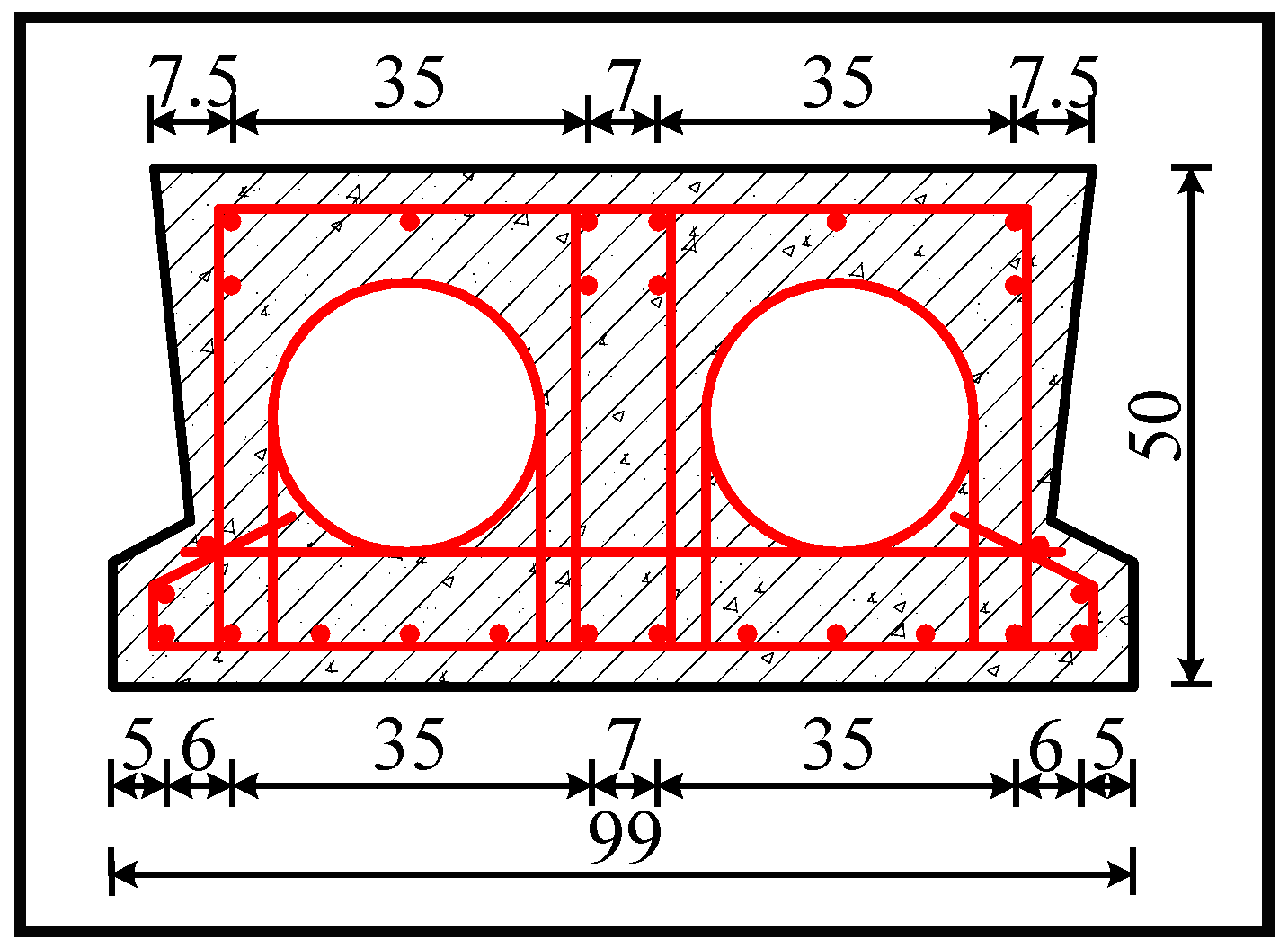
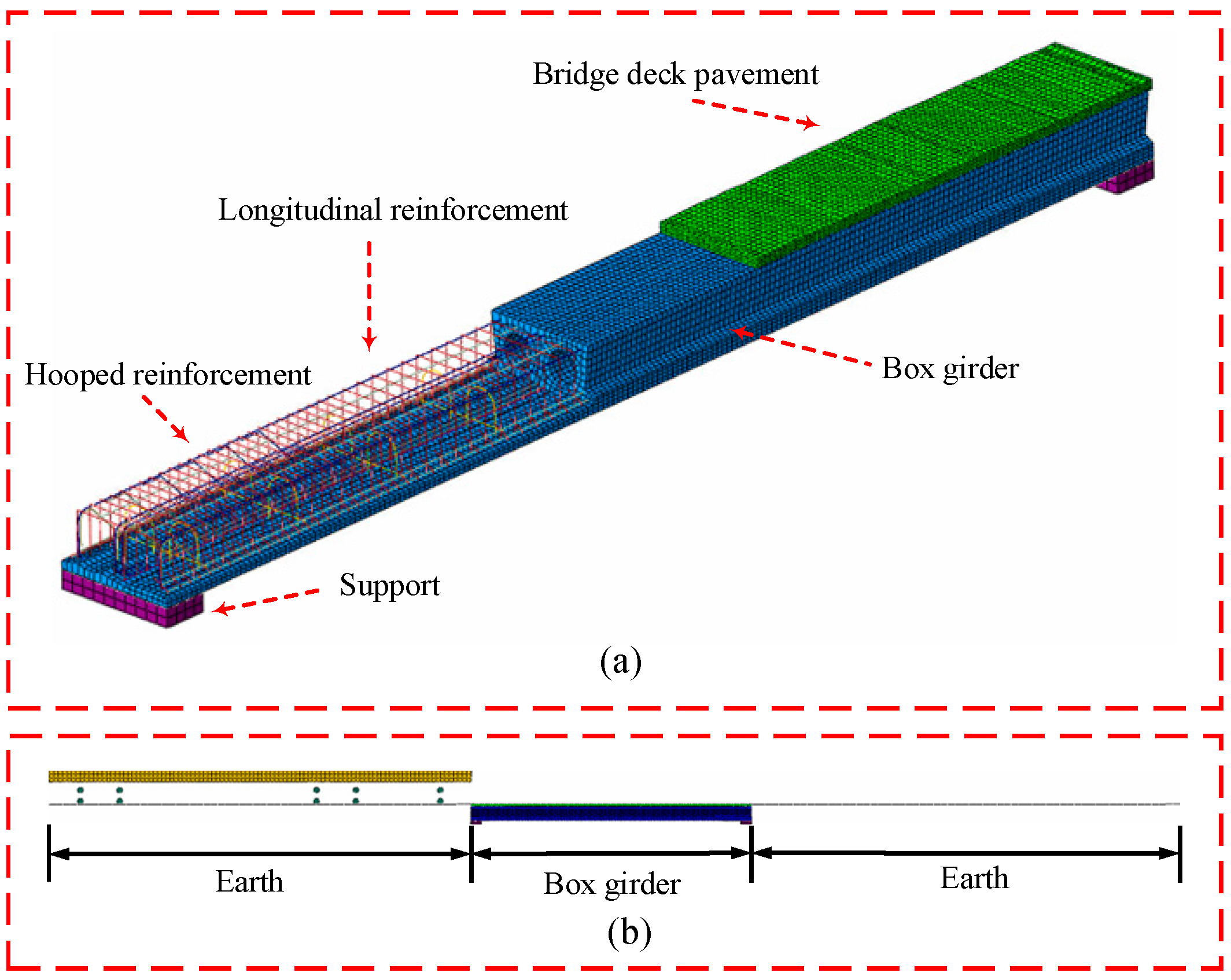
Considering the design drawings and the measured geometric size, the box girder with the following descriptions is obtained: a length of 10 m, a concrete grade of C30, a longitudinal ordinary steel bar HRB335, with a diameter of 20 mm, and a stirrup R235 with a diameter of 10 mm. The section arrangement of the ordinary steel bar is shown in Figure 2. The three-dimensional finite element model of the box girder is established using the numerical analysis software ABAQUS, as shown in Figure 3. The earth model is established in order to simulate the connection between the box girder and the surface of the road. The tie contact in the ABAQUS is applied to the box girder and the earth, as well as the bridge deck pavement, where the steel reinforcement is embedded into the concrete. The normal hard contact in ABAQUS is applied to the vehicle and the box girder that is supported at each end of the bearings. There are 43,339 elements in total, with the concrete using a C3D8R element and the ordinary steel using a T3D2 element. Hexahedral mesh is adopted by the solid element of the model to ensure accuracy and convergence. Considering the calculation accuracy and operation cost, the max element size of the entire bridge is 0.05 m.

3.2. Material Model

3.2.1. Constitutive Model of Concrete

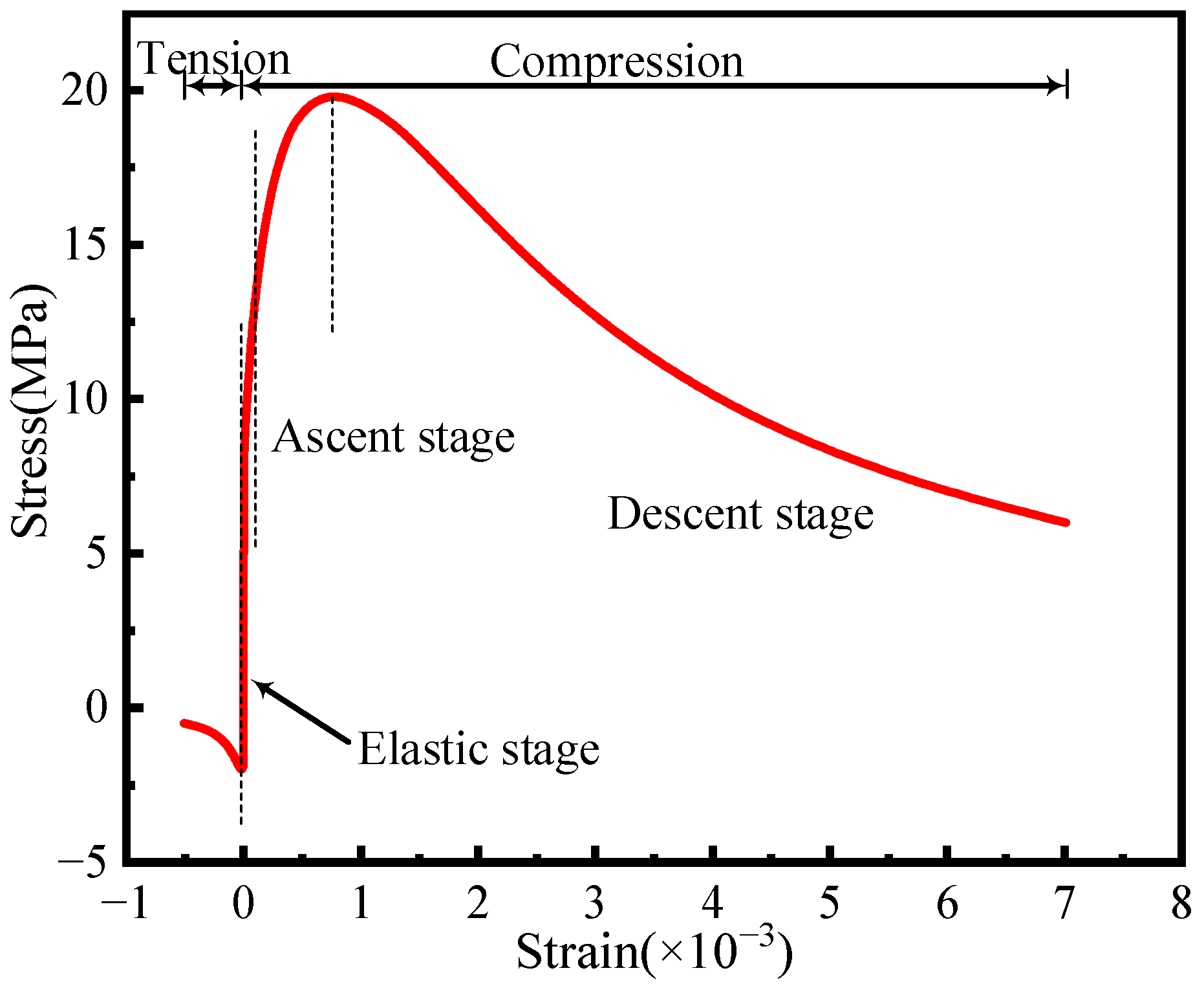
The concrete damaged plasticity model (CDP model) within the ABAQUS software is used to simulate the concrete materials. The uniaxial stress–strain relationship is determined according to the ‘Code for design of concrete structures’, as shown in Figure 4.
The CDP model requires an input of the yield criterion, as well as the flow and hysteresis rules to define concrete damage. According to references [25,26,27,28], the yield surface function control parameter is 0.667, the expansion angle is 38 ° , the eccentricity is 0.1, the biaxial and uniaxial ultimate compressive strength ratio is 1.16, and the viscosity coefficient is 5 × 10 4 . The damage parameter of concrete is shown in Figure 5.

3.2.2. Constitutive Model of Steel

The ordinary rebar material is simulated using the bilinear elastic–plastic mode, which considers the strengthening phase instead of fracture failure. The yield stress, tensile strength, and other material parameters are calculated according to the code for design of the concrete structures [29]. The stress–strain relationship and material parameters are shown in Figure 6 and Table 1, respectively, where σ s , y and σ s , u are the yield and ultimate strength of the steel rebar, respectively; ε s , y and ε s , u are the yield and peak strain of the steel rebar, respectively.

3.3. Vehicle Model

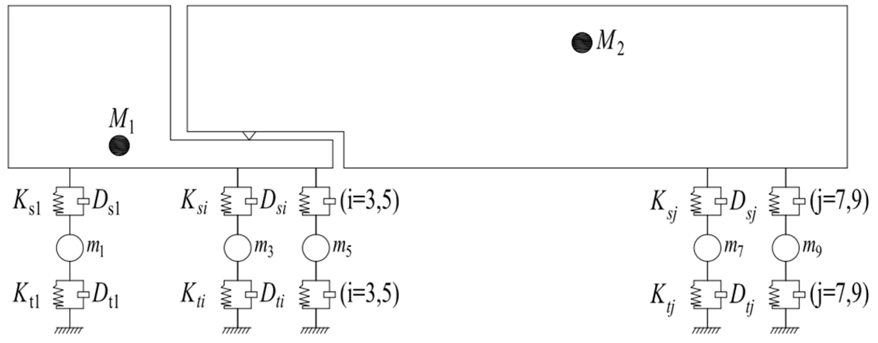
An accurate vehicle model contributes to reflecting the dynamic response of the bridge. A five-axle vehicle model proposed by Deng Lu et al. [30], based on the Chinese bridge vehicle specification design, was adopted and has been validated for its ability to obtain a dynamic bridge response. The relevant mechanical parameters are shown in Figure 7 and Table 2.

3.4. Vehicle–Bridge Interaction Model

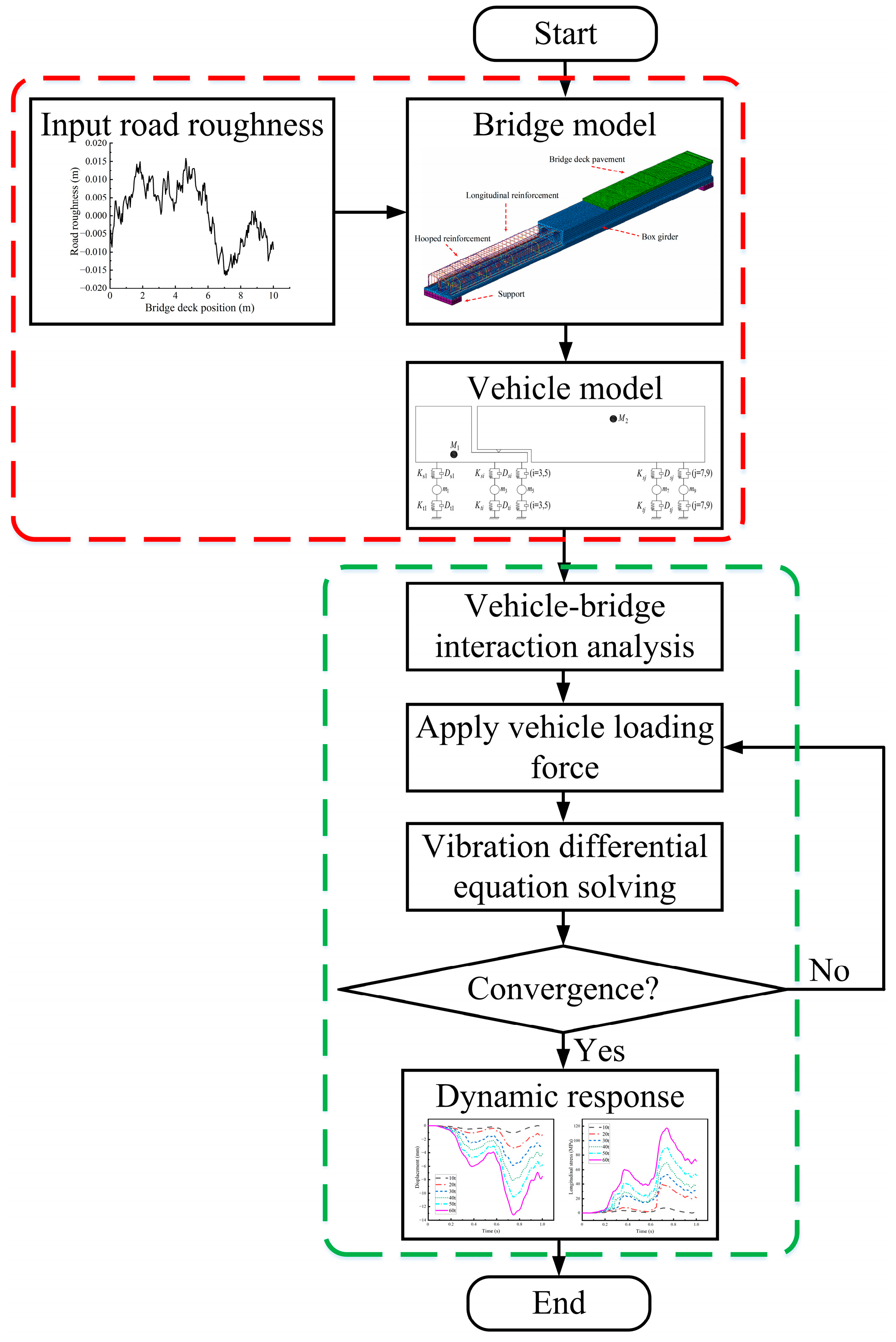
The irregularity of the bridge’s deck and the vibration state of the vehicle and the bridge change due to the location of the vehicle changing when the vehicle is driving on the bridge’s deck; this is a time-varying random complex process. Utilizing ABAQUS to simulate the process of ‘a vehicle crossing a bridge’, it is assumed that the initial displacement, velocity, and acceleration of the vehicle and the bridge are zero. The irregularity of the bridge’s deck and displacement is the excitation of the next time step, acting on the vehicle and bridge’s subsystem. Applying the road roughness curve compiled by computer software to the bridge’s deck can quickly complete the model, improve calculation efficiency, and shorten calculation time. The process of solving the dynamic response of the vehicle–bridge interaction system is shown in Figure 8.

3.5. Model Verification

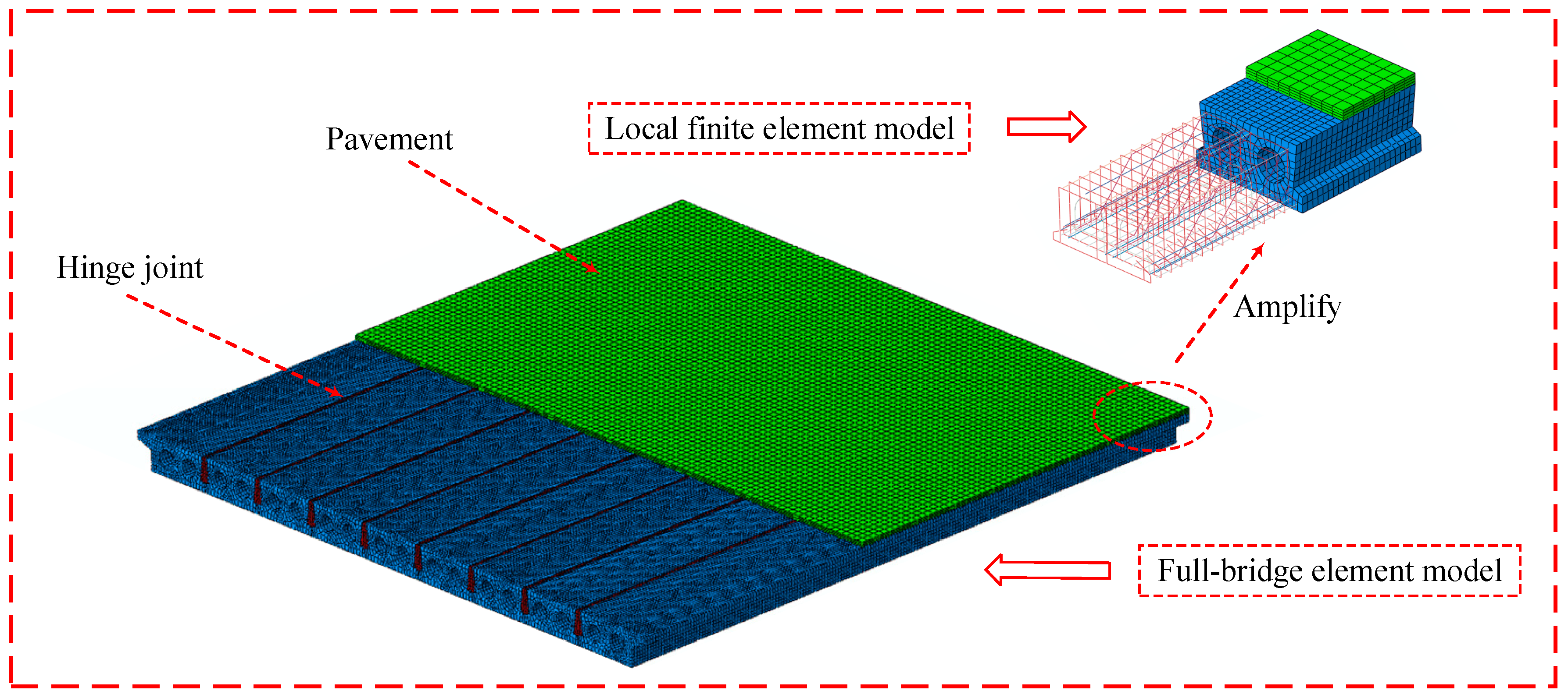
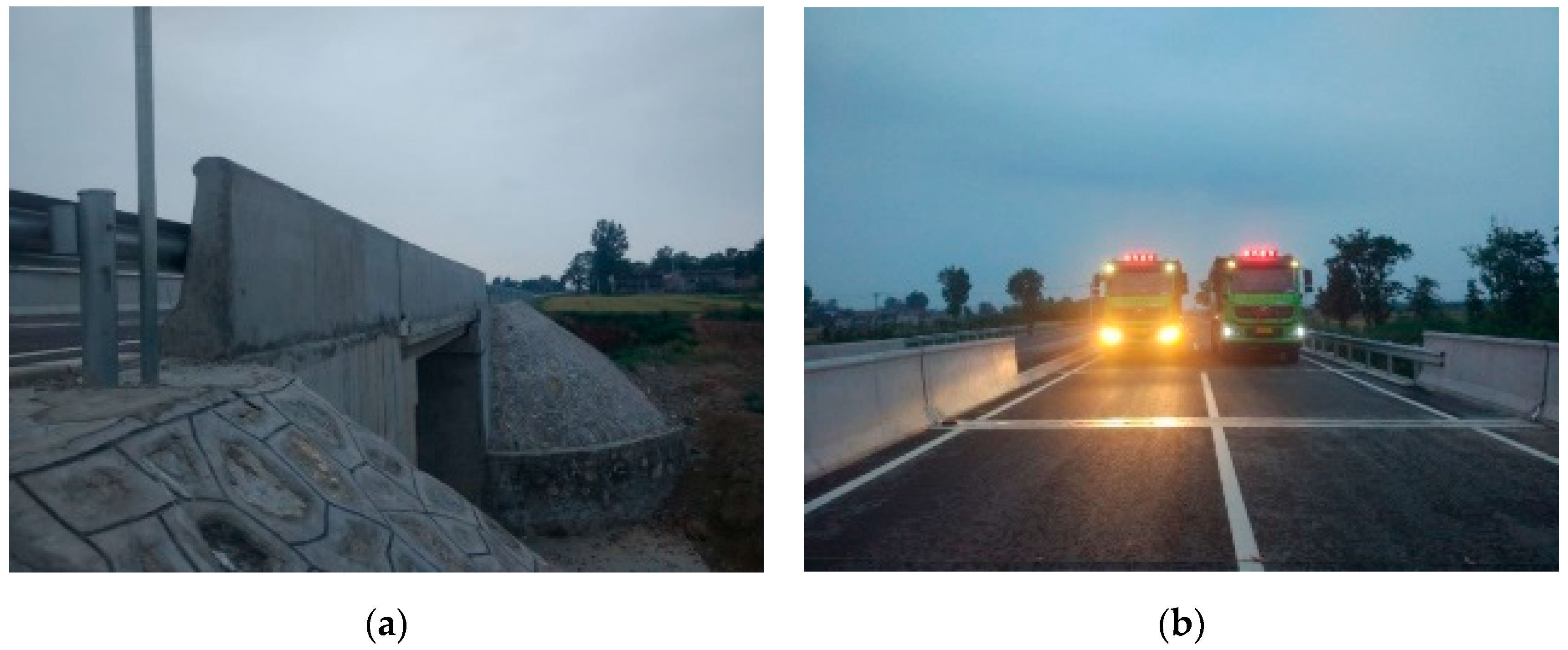
An RC box girder bridge structure with a length of 10 m, is used to verify the rationality of the vehicle model and the road roughness simulation, with a bridge deck width of 9.5 m. The main girder consists of nine box girders in a longitudinal direction with dimensions of 0.5 m high and 0.99 m wide. The bridge’s deck pavement is repaved every two years and can be identified as a grade A road roughness. Next, a series of grade A random road roughness samples are calculated, and their average values are analyzed. The test vehicle has a mass of 59.86 t, and the truck’s parameters are shown in Table 3. The quality of the five-axle vehicle model is the same as that of the test vehicle (other parameters remain unchanged) [30], which is used for numerical simulation according to the actual bridge test conditions. The full-bridge finite model is shown in Figure 9. The test site condition of the RC box girder is shown in Figure 10. To verify the applicability of the numerical model, we compared the full-scale test and the simulation results. The measuring point of the strain is located at the mid-span.
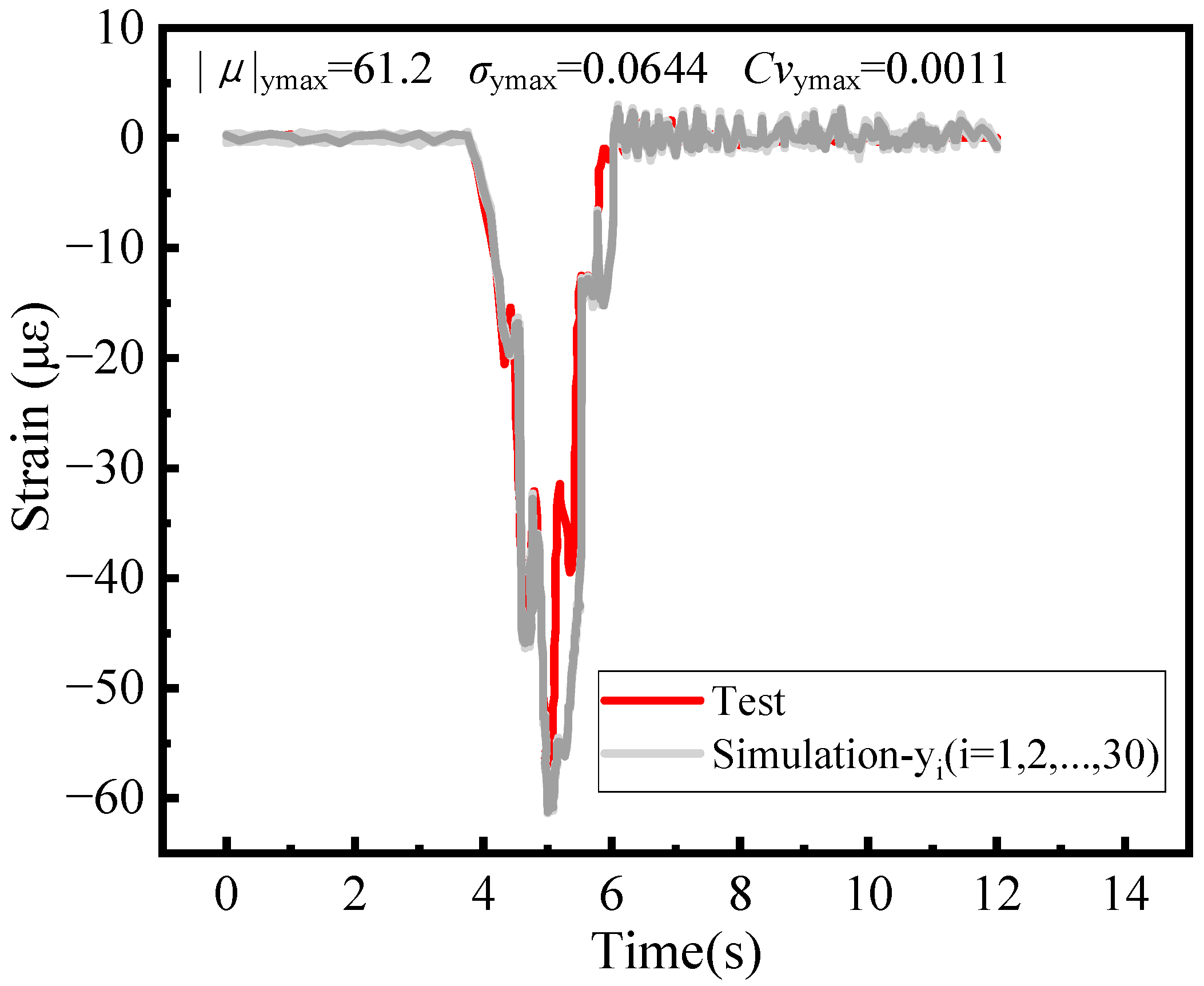
The dynamic strain of girder #5′s mid-span at 50 km/h is calculated 30 times and is shown in Figure 11. The coefficient of variation of the maximum dynamic strain is 0.0011, revealing that the dispersion of the simulation after 30 calculations is minimal. It is evident from Figure 11 that the trend of the test and the simulation strain value is in agreement, with the simulation value being slightly larger. The maximum strain at the mid-span is shown in Table 4. The error between the test and the simulation value occurs due to complex test conditions and different vehicle speeds. From Table 4, the relative errors at different speeds between the test and the simulation are 5.05%, 6.49%, and 6.05%. The comparison of the frequency test and the simulation values are shown in Table 5 and it is clear that the relative errors of the first three-order frequencies using simulations and tests are 3.85%, 8.48%, and 2.62%. Therefore, it can be concluded that the strain–time curve of the box girder model in this study and the full-scale results are in agreement, verifying the reliability of the numerical analysis model based on a five-axle vehicle and road roughness to obtain the vehicle–bridge interaction dynamic response analysis.

4. Damage Description of Single Box Girder

The structural damage caused by the vehicle driving on the bridge is affected by the vehicle and bridge parameters. In this study, vehicle mass, vehicle speed, concrete strength, and longitudinal reinforcement ratio are selected as the main analysis parameters. Moreover, concrete damage is defined by damage level while 0 represents no damage and 1 represents failure. To obtain the damage status, the vehicle–bridge interaction system is used to obtain the damage distribution and damage mode of the bridge under different typical conditions. The calculation parameters are a total of 13 typical conditions; the calculation parameters and damage descriptions of each scheme are shown in Table 6.
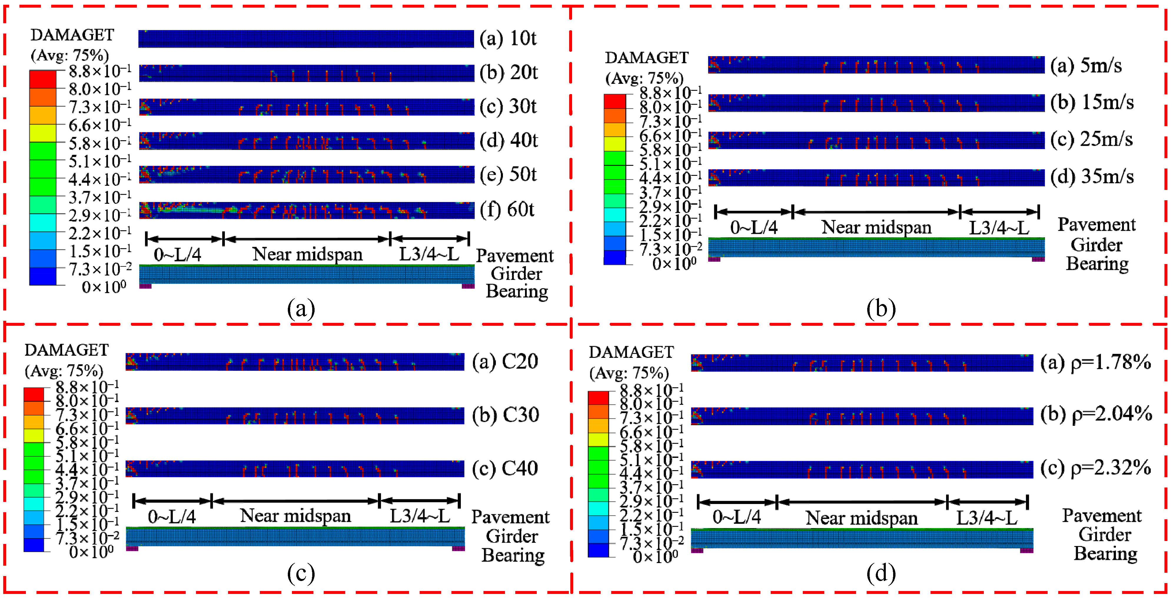
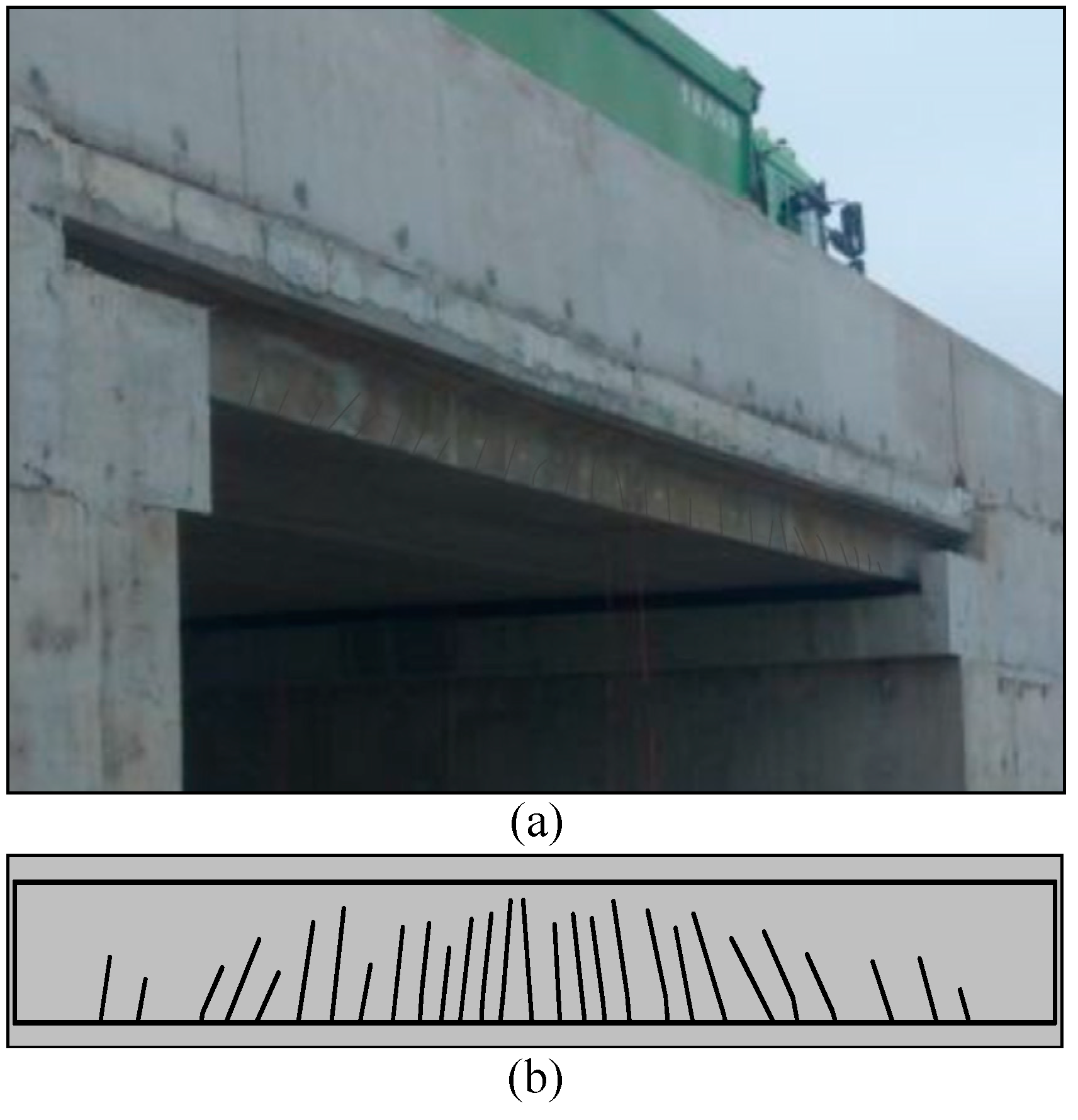
After a vehicle passes on the bridge, box girder damage can be observed. Figure 12a shows the damage status of the box girder with different vehicle loads. The flexural deformation of girder causes concrete damage. It is worth noting that the damaged area extends from the mid-span region to the region near support when the unilateral vehicle mass is 10 t to 60 t. In addition, the damage mode varies from no damage and the flexural damage to the flexural-shear damage in box girder and concrete shear damage near support as the vehicle mass increases. The damage mode analyzed is basically in agreement with the field-measured crack diagram as shown in Figure 13, which also verifies the accuracy of the finite element simulation in this study. The most serious damage is observed when the vehicle mass is 60 t.
The damage status of the box girder under different vehicle speeds is shown in Figure 12b. As with the scheme of different vehicle mass, a similar damage region is observed with the vehicle speed parameter. As the vehicle speed increases, the damage mode varies from the flexural damage to the flexural-shear damage in the box girder, and the shear damage disappears, while the concrete near the bearer has shear damage. Therefore, the shear capacity near the bearer is seriously deteriorated and needs to be paid more attention during operation. The most severe damage occurs at the vehicle speed of 25 m/s.
Similarly, the damage mode transition of the box girder under different concrete strength grades and longitudinal reinforcement ratios is similar to different vehicle speeds as shown in Figure 12c,d. Furthermore, as the concrete strength or longitudinal reinforcement ratio increases, the damaged region of the box girder decreases with damage mode transition. As a result, increasing the concrete strength and longitudinal reinforcement ratio under a moving vehicle load could be a better choice to reduce the damage region and eliminate shear damage in the box girder.

5. Discussion

After detailed and cautious calculation, the structural damage is concluded as indicated in Table 6. Using the vehicle–bridge interaction system, the damage could be systemized in three modes: flexural damage in the box girder, flexural-shear damage in the box girder, and shear damage near the supports.
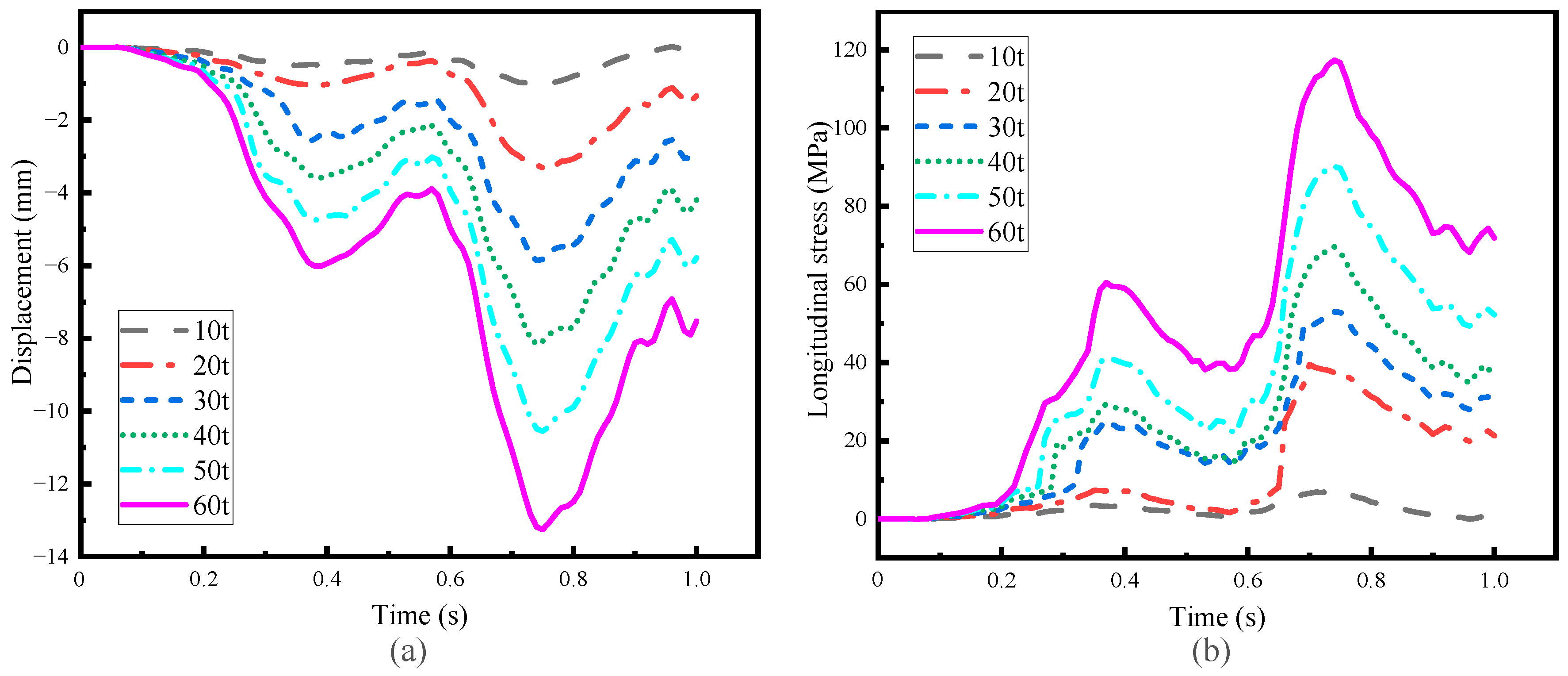
To analyze the damage mechanism, the displacement and the longitudinal stress time histories are presented. Limited to space constraints, only the time history under different vehicle mass is given, as shown in Figure 14. From Figure 14a, it is clear that the vertical deflection increases as the vehicle mass increases. This model can reflect the bending damage of the box girder. The relative residual deformation also increases as the vehicle mass increases. Moreover, the displacement and the longitudinal stress time histories exhibit a trend of increase and decrease owing to the differences in damping and stiffness between the front and the rear wheels. The longitudinal stress of the steel bar at the mid-span increases but with no yielding as the vehicle load increases. The results based on other analyzed parameters are similar to the trend of vehicle mass.
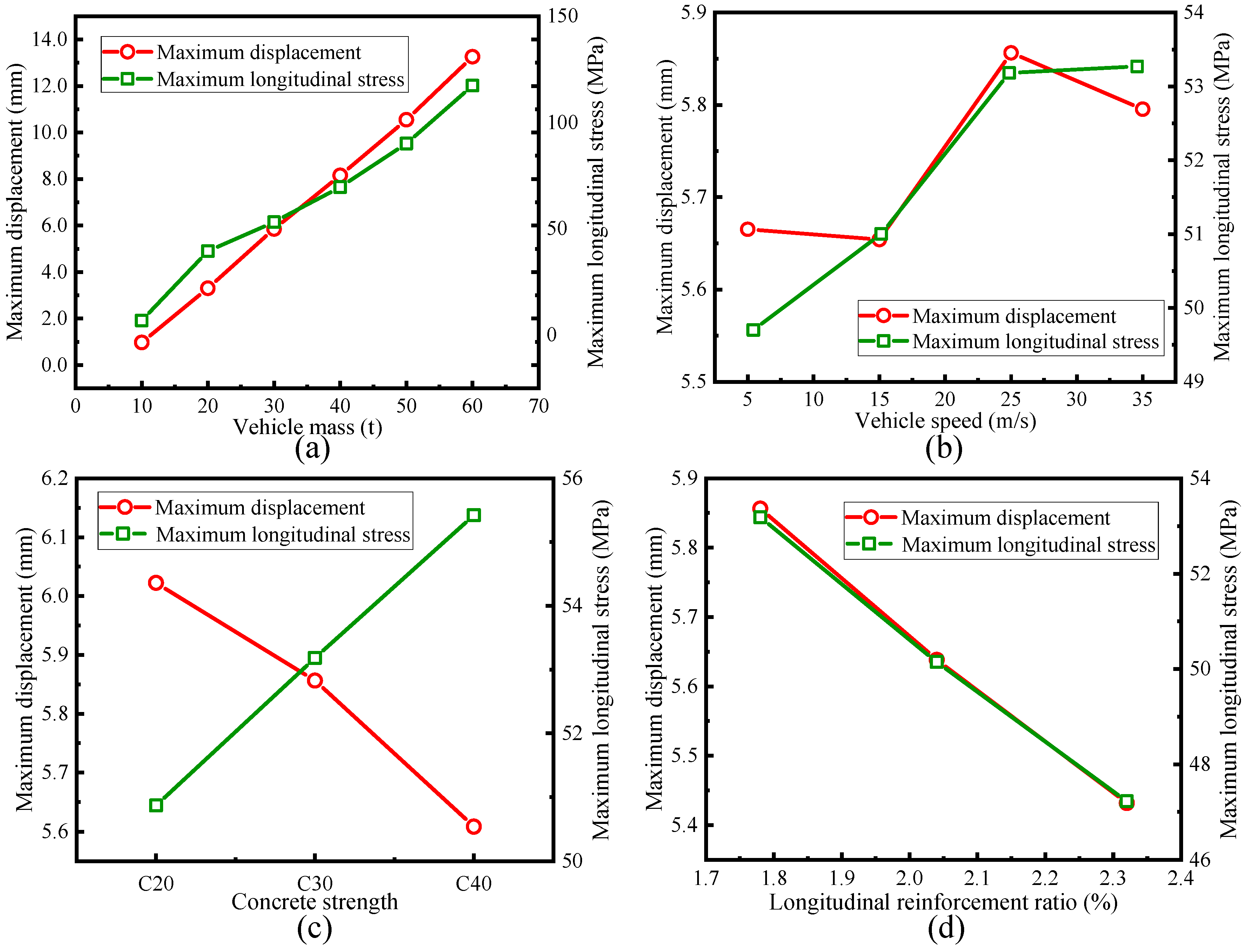
The maximum displacement and the longitudinal stress values of all the parameters of the analysis results are plotted in Figure 15. With the increase in vehicle mass, the mid-span displacement response increases gradually, which may be caused by the vehicle mass and excitation frequency that is close to the bridge frequency, leading to a gradual increase in the damage status.
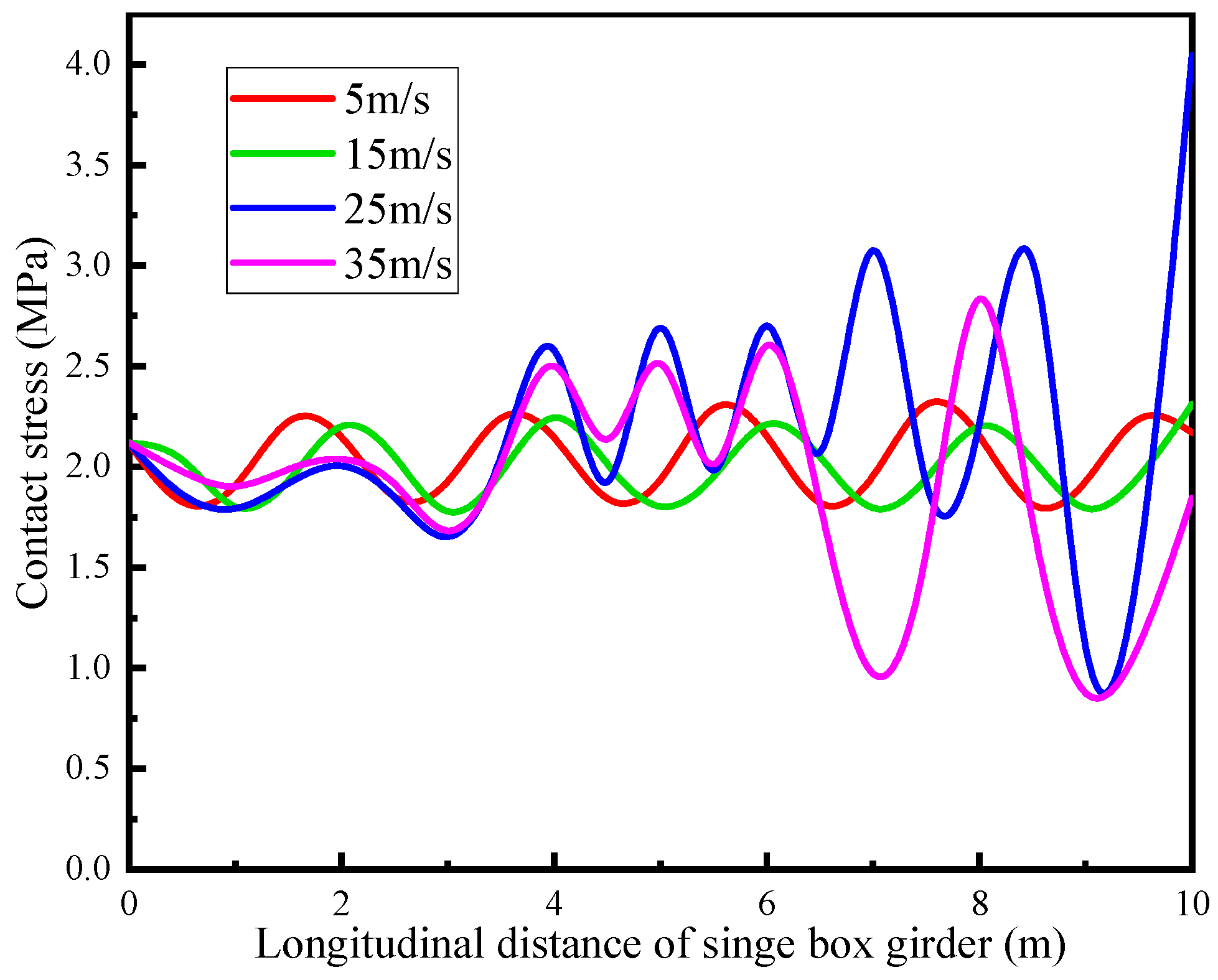
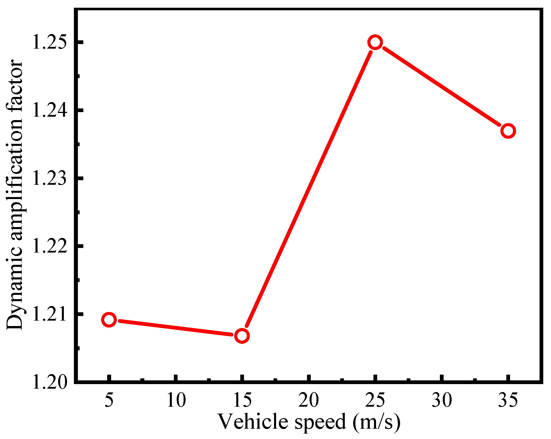
The maximum vertical dynamic displacement and the maximum longitudinal stress of the steel bar increase nonlinearly when the vehicle speed increases. Furthermore, the mid-span displacement response rapidly increases for all vehicle mass analyses at a speed of 25 m/s. This significant increase may be due to the local resonance caused by the excitation frequency close to the bridge frequency caused by the road roughness under the load of the vehicle, thus increasing the damage status. This can be verified by the contact stress time history, as shown in Figure 16. The dynamic amplification factor of the bridge at different vehicle speeds as depicted in Figure 17. It shows that the dynamic amplification factor is larger when the speed is 25 m/s, indicating that the vehicle has a greater impact on the bridge at this speed. After the vehicle passes the bridge, the displacement response does not return to the original state, proving that there is a cumulative damage effect in the box girder within the vehicle–bridge interaction system, and the relative residual deformation can be directly proven. Due to the cumulative damage, the bridge may also be damaged under the action of minimal load and low speed.
With an increase in concrete strength, the mid-span displacement response gradually decreases, which is consistent with the trend of the longitudinal reinforcement ratio. It can be seen from Figure 15a that as the vehicle mass increases, the stress of steel bars gradually increases, indicating that steel bars play an important role within the concrete girders. The trend of the maximum longitudinal stress under different vehicle mass is consistent with vehicle speed and concrete strength and is opposite to the trend of the longitudinal reinforcement ratio.
In addition, to reduce the damage caused by the vehicle, four main factors are analyzed. From the above analysis, limiting speed below 25 m/s under the vehicle mass (10 t to 60 t) and increasing concrete strength and reinforcement ratio in a certain range are suggested to improve the anti-damage performance and reduce the damage of the girder.

6. Conclusions

This study proposed a plate stress analysis method for an RC box girder based on damage mechanisms. The accuracy and effectiveness of the proposed method for the RC box girder were verified based on numerical simulations and full-scale tests. The results showed that the strain calculated by the numerical simulation was reasonably accurate compared to the full-scale test with the largest difference of 7%. The implicit dynamic damage numerical analysis based on the Newmark algorithm, and the five-axle vehicle and road roughness models, can reflect the damage status and the dynamic characteristics of the RC box girder under a moving vehicle load.
The effects of the vehicle mass, speed, concrete strength grade, longitudinal reinforcement ratio of the damage status, the vertical deflection of the mid-span, and the longitudinal reinforcement stress were analyzed using a solid finite element vehicle–bridge interaction dynamic elastic–plastic analysis. The results showed that the damage status of the box girder was considerably affected by a moving vehicle mass and vehicle speed. Furthermore, the damage could be systemized in three modes under the moving vehicles: flexural damage in the box girder, flexural-shear damage in the box girder, and shear damage near the support. In addition, the damage to the RC box girder under a moving vehicle load can be reduced by limiting speed below 25 m/s under the vehicle mass (10 t to 60 t) and increasing concrete strength and reinforcement ratio in a certain range. The proposed method can provide an important reference for the maintenance and quantitative damage assessment of RC box girders under a plate stress state.

Author Contributions

Conceptualization, B.Z. and Y.H.; methodology, B.Z.; validation, X.Z.; formal analysis, Y.H.; software, B.Z.; investigation, B.Z.; data curation, X.Z.; writing—original draft preparation, B.Z. and Y.H.; writing—review and editing, B.Z. and X.Z.; funding acquisition, Y.H. and X.Z. All authors have read and agreed to the published version of the manuscript.

Funding

This research was funded by the financial support from the Major Project of Key R&D Program of Ningxia Hui Autonomous Region in China (No. 2020BFG02005) and the Natural Science Foundation of Shaanxi (No. 2022JQ-415).

Data Availability Statement

Not applicable.

Conflicts of Interest

The authors declare that they have no conflict of interest to report regarding the present study.

References

  1. Hussein, H.H.; Sargand, S.M.; Khoury, I.; Al-Jhayyish, A.K. Environment induced behavior of transverse tie bars in adjacent prestressed box-girder bridges with partial depth shear keys. J. Perform. Constr. Fac. 2017, 31, 04017074. [Google Scholar] [CrossRef]
  2. Hhha, B.; Sms, A.; Ftar, A.; Eps, A. Experimental validation of optimized ultra-high-performance concrete shear key shape for precast pre-stressed adjacent box girder bridges. Constr. Build. Mater. 2018, 190, 178–190. [Google Scholar]
  3. Lucie, K.; Janda, T.; Jan, S.; Michal, S.; Guido, M. Experimental and numerical investigation of the response of GLT beams exposed to fire. Constr. Build. Mater. 2021, 299, 123846. [Google Scholar]
  4. Huang, Y.; Han, B.; Yin, W.M. Reinforced Concrete Corbels Shear Test: The Triangular-Truss Method Evaluation. Buildings 2022, 12, 1619. [Google Scholar] [CrossRef]
  5. Au, A.; Lam, C.; Au, J.; Tharmabala, B. Eliminating Deck joints using debonded link slabs: Research and field tests in Ontario. J. Bridge Eng. 2013, 18, 768–778. [Google Scholar] [CrossRef]
  6. Semendary, A.A.; Walsh, K.K.; Steinberg, E.P. Early-Age Behavior of an Adjacent Prestressed Concrete Box-Beam Bridge Containing UHPC Shear Keys with Transverse Dowels. J. Bridge Eng. 2017, 22, 01017007. [Google Scholar] [CrossRef]
  7. Hussein, H.H.; Sargand, S.M.; Steinberg, E.P. Shape Optimization of UHPC Shear Keys for Precast, Prestressed, Adjacent Box-Girder Bridges. J. Bridge Eng. 2018, 23, 04018009. [Google Scholar] [CrossRef]
  8. Leng, Y.L.; Zhang, J.Q.; Cheng, S.S.; Hai, F. Numerical analysis on single plate loading effect of precast hollow plate girder bridge. J. Highw. Transp. Res. Dev. 2013, 30, 63–73. [Google Scholar]
  9. Zhang, J.F.; Kong, L.Y.; Han, W.S.; Li, X.Z. Damage Mechanism and Post collision Bearing Capacity of Prestressed Concrete Hollow Slab Bridge Under Overheight-vehicle Collision. China J. Highw. Transp. 2021, 34, 177–187. [Google Scholar]
  10. Al-Saidy, A.H.; Klaiber, F.W.; Wipf, T.J.; Al-Jabri, K.S.; Al-Nuaimi, A.S. Parametric study on the behavior of short span composite bridge girders strengthened with carbon fiber reinforced polymer plates. Constr. Build. Mater. 2008, 22, 729–737. [Google Scholar] [CrossRef]
  11. Yang, D.H.; Yi, T.H.; Li, H.N. Coupled fatigue-corrosion failure analysis and performance assessment of RC bridge deck slabs. J. Bridge Eng. 2017, 20, 04017077. [Google Scholar] [CrossRef]
  12. Ma, Y.L.; Wang, D.W.; Li, G.H. Evaluation of load-bearing capacity of pre-stressed concrete hollow slab based on single slab load bearing. J. Highw. Transp. Res. Dev. 2013, 30, 45–55. [Google Scholar]
  13. Su, X.; Yin, S.P.; Yang, Y.H.; Feng, J.; Li, L.T. Comparative analysis of flexural performance of old full-scale hollow slab beams reinforced with fiber composites. Constr. Build. Mater. 2022, 338, 127657. [Google Scholar]
  14. Jin, H.; Xu, Y.; Zheng, Q.C.; Shao, G.T. Application of shaped steel and concrete composite reinforcement technique to hollow slab bridge. Bridge Constr. 2017, 47, 114–118. [Google Scholar]
  15. Deng, L.; Chen, Y.X.; Han, W.S.; Wang, W. Studying impact factors for short and medium-span simply supported concrete highway bridge and its suggested values. China J. Highw. Transp. 2020, 33, 69–78. [Google Scholar]
  16. Deng, L.; He, W.; Wang, F. Dynamic impact factors for simply supported bridges with different cross-section types. J. Vib. Shock 2015, 34, 70–75. [Google Scholar]
  17. Deng, L.; Duan, L.L.; Zou, Q.L. Comparison of dynamic amplification factors calculated from bridge strain and deflection. Eng. Mech. 2018, 35, 126–135. [Google Scholar]
  18. Gao, Q.F.; Wang, Z.L.; Koh, C.G.; Chen, C. Dynamic Load Allowances Corresponding to Different Responses in Various Sections of Highway Bridges to Moving Vehicular Loads. Adv. Struct. Eng. 2015, 18, 1685–1702. [Google Scholar] [CrossRef]
  19. Bu, J.Q.; Lou, G.C.; Luo, S.X. Analysis of impact effects of moving vehicles on a continuous bridge. J. Vib. Shock. 2007, 26, 52–55+64. [Google Scholar]
  20. Aloisio, A.; Rosso, M.M.; Alaggio, R. Experimental and analytical investigation into the effect of ballasted track on the dynamic response of railway bridges under moving loads. J. Bridge Eng. 2022, 27, 04022085. [Google Scholar] [CrossRef]
  21. Li, H.; Wang, T.Y.; Wu, G. A Bayesian deep learning approach for random vibration analysis of bridges subjected to vehicle dynamic interaction. Mech. Syst. Signal Pr. 2022, 170, 108799. [Google Scholar] [CrossRef]
  22. Jian, X.D.; Xia, Y.; Sun, L.M. Indirect identification of bridge frequencies using a four-wheel vehicle: Theory and three-dimensional simulation. Mech. Syst. Signal Pr. 2022, 177, 109155. [Google Scholar] [CrossRef]
  23. Zhao, L.W. The Analysis of Vehicle-bridge Coupling Vibration of CFST. Master’s Thesis, Zhengzhou University, Zhengzhou, China, 2017. [Google Scholar]
  24. Vehicle Vibration-Describing Method for Road Surface Irregularity (GB/T7031-86); China National Standard. China Standards Press: Beijing, China, 1986.
  25. Zhang, J.; Wang, Q.Y.; Hu, S.Y. Parameters verification of concrete damaged plastic model of ABAQUS. Build. Struct. 2008, 38, 127–130. [Google Scholar]
  26. Nie, J.G.; Wang, Y.H. Comparison study of constitutive model of concrete in ABAQUS for static analysis of structure. Eng. Mech. 2013, 30, 59–82. [Google Scholar]
  27. Kupfer, H.B.; Geretle, K.H. Behavior of conc-rete under biaxial stresses. J. Eng. Mech. Div. 1973, 99, 853–866. [Google Scholar] [CrossRef]
  28. Kachanov, L.M. Rupture time under creep conditions. Int. J. Fract. 1999, 97, 11–18. [Google Scholar] [CrossRef]
  29. Code for Design of Concrete Structrues (GB 50010); China National Standard. China Architecture & Building Press: Beijing, China, 2010.
  30. Deng, L.; Duan, L.L.; He, W.; Ji, W. Study on vehicle model for bridge coupling vibration of highway bridges in China. China J. Highw. Transp. 2018, 31, 92–100. [Google Scholar]
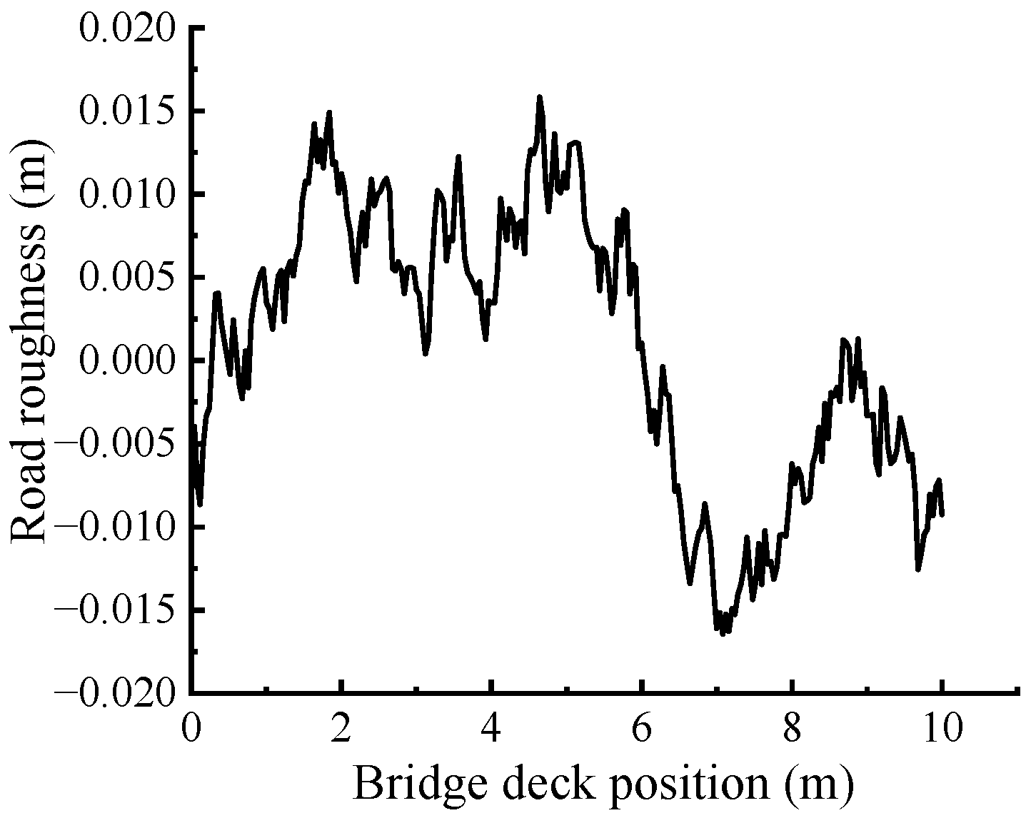
Figure 1. Grade A road roughness.
Buildings 13 00547 g001
Figure 2. Section arrangement of the ordinary steel bar (unit: cm).
Buildings 13 00547 g002
Figure 3. Finite element model: (a) box girder; (b) whole bridge.
Buildings 13 00547 g003
Figure 4. Constitutive model of concrete.
Buildings 13 00547 g004
Figure 5. Concrete damage parameter.
Buildings 13 00547 g005
Figure 6. Constitutive model of steel.
Buildings 13 00547 g006
Figure 7. Five-axle vehicle analysis model.
Buildings 13 00547 g007
Figure 8. Analysis flow chart of the vehicle–bridge interaction system.
Buildings 13 00547 g008
Figure 9. Full-bridge finite element model.
Buildings 13 00547 g009
Figure 10. Bridge photographs: (a) field test; (b) field test vehicle.
Buildings 13 00547 g010
Figure 11. Strain comparison of girder #5 at 50 km/h.
Buildings 13 00547 g011
Figure 12. Damage status of the box girders: (a) different vehicle mass; (b) different vehicle speed; (c) different concrete strength grades; (d) different longitudinal reinforcement ratios.
Buildings 13 00547 g012
Figure 13. Crack Distribution: (a) box girder in site; (b) schematic drawing.
Buildings 13 00547 g013
Figure 14. Time history at mid-span under different vehicle mass: (a) displacement; (b) longitudinal stress.
Buildings 13 00547 g014
Figure 15. Maximum displacement and longitudinal stress for each component: (a) vehicle mass; (b) vehicle speed; (c) concrete strength; (d) longitudinal reinforcement ratio.
Buildings 13 00547 g015
Figure 16. Contact stress between the wheel and the girder.
Buildings 13 00547 g016
Figure 17. Dynamic amplification factor at different vehicle speeds.
Buildings 13 00547 g017
Table 1. Steel material parameters.
Materialεs,y (10−3)σs,y (MPa)εs,u (10−3)σs,u (MPa)
R2351.1192350.100370
HRB3351.6753350.075455
Table 2. Vehicle model analysis parameters.
ParameterValueParameterValue
Suspension stiffness Ks1, Ks2300 kN·m−1M12276.5 kg
Suspension stiffness Ks3~Ks6500 kN·m−1M245,246 kg
Suspension stiffness Ks7~Ks101250 kN·m−1m1700 kg
Tire stiffness Kt1, Kt21500 kN·m−1m31000 kg
Tire stiffness Kt3~Kt103000 kN·m−1m51000 kg
Suspension damping Ds1, Ds210 kN·s·m−1m7800 kg
Suspension damping Ds3~Ds1053 kN·s·m−1m9800 kg
Suspension damping Dt1~Dt103 kN·s·m−1
Table 3. Parameters of three-axle truck.
ParameterValue
Mass of truck body59,860 kg
Mass of the front axle11,932 kg
Mass of the middle axle23,964 kg
Mass of the rear axle23,964 kg
Distance between the front and middle axle3.6 m
Distance between the middle and rear axle1.4 m
Distance of transverse axial1.8 m
Table 4. Maximum strain at mid-span.
Vehicle Speed (km/h)Test Value (με)Simulation Value (με)Relative Error (%)
3039.641.65.05
4038.541.06.49
5057.861.36.05
Table 5. Comparison of test and simulation frequency.
Measured OrderTest Value (Hz)Simulation Value (Hz)Relative Error (%)
113.012.53.85
216.515.18.48
334.333.42.62
Table 6. Parameters of load cases.
SchemeL a
(t)
S a
(m/s)
C a
(MPa)
Ρ a
(%)
Damage Description
11025C301.78No damage
22025C301.78Flexural damage in box girder
33025C301.78Flexural-shear damage in box girder and concrete shear damage near support
44025C301.78Flexural-shear damage in box girder and concrete shear damage near support
55025C301.78Flexural-shear damage in box girder and concrete shear damage near support
66025C301.78Flexural-shear damage in box girder and severe shear damage near support
7305C301.78Flexural damage in box girder and concrete shear damage near support
83015C301.78Flexural damage in box girder and concrete shear damage near support
93035C301.78Flexural damage in box girder and concrete shear damage near support
103025C201.78Flexural-shear damage in box girder and concrete shear damage near support
113025C401.78Flexural damage in box girder and concrete shear damage near support
123025C302.04Flexural damage in box girder and concrete shear damage near support
133025C302.32Flexural damage in box girder and concrete shear damage near support
a L stands for vehicle mass, S stands for vehicle speed, C stands for concrete strength, and ρ stands for longitudinal reinforcement ratio.
Disclaimer/Publisher’s Note: The statements, opinions and data contained in all publications are solely those of the individual author(s) and contributor(s) and not of MDPI and/or the editor(s). MDPI and/or the editor(s) disclaim responsibility for any injury to people or property resulting from any ideas, methods, instructions or products referred to in the content.