Article

Characterization of Envelope Air Leakage Behavior for Centrally Air-Conditioned Single-Family Detached Houses

Architectural Engineering Department, College of Design and Built Environment, King Fahd University of Petroleum and Minerals, Dhahran 34464, Saudi Arabia
*
Author to whom correspondence should be addressed.
Buildings 2023, 13(3), 660; https://doi.org/10.3390/buildings13030660
Submission received: 24 January 2023 / Revised: 19 February 2023 / Accepted: 21 February 2023 / Published: 2 March 2023
(This article belongs to the Section Building Energy, Physics, Environment, and Systems)

Abstract

:
Air leakage is an essential factor contributing to overall building performance. It plays a major role in determining energy consumption in harsh climates, particularly in residential buildings, as it represents a significant component of the envelope-induced thermal load. In centrally air-conditioned houses, the HVAC system can substantially alter the pressure distribution across the exterior envelope, reforming the air leakage behavior. Nonetheless, limited information is available to characterize and better understand such behavior to accurately predict building performance and energy consumption toward meeting the emerging requirements for sustainable buildings. This study experimentally investigated the air leakage behavior of a selected sample of centrally air-conditioned typical single-family detached houses in Saudi Arabia. The air leakage behavior was investigated by measuring the overall airtightness and the contribution of the different air leakage paths using the viable method of the blower door test (BDT). The air leakage rate was then calculated using the measured induced pressure across the envelope during the HVAC system operation. Results indicated that the air leakage behavior is significantly altered by the pressurization induced by the central HVAC system, eliminating air infiltration and producing an outward airflow across the entire envelope. The study addresses a current challenge in characterizing envelope air leakage behavior for a common type of house and, thus, would indirectly contribute to more accurate thermal and energy performance assessments. Several aspects were highlighted for consideration when defining the contribution of air leakage to energy consumption prediction and studying air leakage behavior in other types of buildings.

1. Introduction

According to the International Energy Agency, buildings are one of the major causes of a dramatic increase in energy consumption, accounting for 55% of globally produced electricity and 30% of final energy [1,2]. Another report by the U.S. Energy Information Administration (EIA) predicts that energy consumed in the buildings sector, which includes residential and commercial structures, will increase by 65% between 2018 and 2050, from 26,669 TWh to 40,737 TWh [3]. This rising energy demand is exacerbated by rising income, urbanization, and increased access to electricity [3]. In addition to the financial implications, rising energy demand contributes to greenhouse gas emissions and global warming, as building energy consumption accounts for roughly 40% of total global carbon emissions [4]. The U.S. Energy Information Administration (EIA) reported a 1.8% annual average growth rate in energy-related CO2 emissions between 1990 and 2018, predicting a 50% increase in global energy consumption between 2018 and 2050 [3]. The global energy-related CO2 emissions in 2021 reached a record high, up 6% from 2020 [2]. As a result, most studies in the quest for sustainable buildings have focused on improving overall building performance, with an emphasis on energy, since the building sector consumes the bulk of produced energy.
In harsh climates, the energy consumed by buildings represents a significant component of the total produced energy. The residential sector’s energy demand in the Kingdom of Saudi Arabia, for example, accounts for 50% of the total demand [4]. The Saudi Energy Efficiency Center also estimates that the residential sector consumes more than half of the electricity available in the Kingdom [5]. In 2017, the residential sector in Saudi Arabia consumed approximately 143,000 GWh of electricity, with 70% of that consumed for cooling [6]. The bulk of this energy is used for either cooling or heating to control the indoor environment and maintain the space in desirable conditions [7,8].
Building airtightness is a critical building characteristic that plays a vital role in the energy performance of buildings, since the additional cooling/heating loads induced by air leakage may result in a considerable increase in energy used by the heating, ventilating, and air conditioning (HVAC) systems [9,10,11,12]. Furthermore, air leakage plays a crucial role in determining indoor environmental quality, which affects occupants’ thermal comfort, health, and productivity and air conditioning system design, selection, and performance [13,14,15,16].
Outdoor air is introduced into buildings through two means. In the first, through the ventilation system, either natural or mechanical, the outdoor air is intentionally introduced to improve and maintain indoor air quality by diluting indoor air contaminants. In the second, the air infiltrates through the exterior envelope components under thermal and/or wind-induced pressures. The American Society of Heating, Refrigerating, and Air-Conditioning Engineers (ASHRAE) defines air infiltration as “the flow of outdoor air into a building through cracks and other unintentional openings and the normal use of exterior doors for entrance and egress” [17].
Infiltration is a physical phenomenon, while airtightness is part of the envelope characteristics that control and quantify the air infiltration flow rate and occurrence [18,19]. Furthermore, infiltration and airtightness can be mathematically linked. According to empirical relations, the building infiltration is 1/20 of its airtightness [20]. However, numerous factors that directly affect air infiltration were not considered in this empirical relation. In 1987, the Lawrence Berkeley Laboratory (LBL) model was developed by Sherman [21]. Sherman proposed the addition of correction factors to consider the effect of the type of cracks, wind exposure, and building height on building air infiltration. Walker and Wilson developed the Alberta air infiltration model in 1990, which considers the total airflow correlated with the wind flow and stack flow [20]. In some studies, air infiltration is referred to as air permeability (m3/h·m2) and is defined as the amount of air that could pass through the building envelope [22]. Therefore, a lower air permeability denotes an airtight envelope capable of reducing the quantity of air that penetrates through it at a given pressure difference.
ASHRAE highlights the importance and determinability of infiltration in residential buildings, specifically while emphasizing ventilation in commercial buildings. However, even in commercial buildings, it recommends that infiltration should not be overlooked [9]. Studies [23,24] have indicated that 40% of buildings’ residential cooling/heating loads were attributed to air infiltration, whereas the infiltration contribution in commercial buildings was 15%. In addition, ASHRAE [25] showed various infiltration contributions of the building components, as presented in Table 1. Other studies have indicated that air infiltration in residential and commercial buildings could be responsible for 25–50% of the total cooling/heating loads [26,27,28]. Studies in the US reveal that energy loss because of air infiltration represents almost one-third of cooling and heating energy in residential buildings and 40% of the heating energy in industrial buildings [14,29]. Furthermore, air infiltration can negatively affect indoor air quality since it may allow for moisture, outdoor particulate matter, and gaseous contaminants inside the building [30,31,32,33].
Logue et al. [34] studied the effect of increasing the airtightness of the US residential building stock on energy consumption. In their model, 50,000 virtual homes, mechanically ventilated, according to ASHRAE 62.2-2013, were considered representative samples. Improving the airtightness of all homes decreased the annual energy consumption by 0.74 exajoules (EJ). Lozinsky et al. [35] indicated that many studies have focused on quantifying the influence of air infiltration on the energy consumption of residential buildings and revealed that infiltration is responsible for 45% of the annual space heating in multi-unit residential homes and 15–30% in single-family homes. Emmerich et al. [36] investigated the effect of air infiltration on the heating and cooling energy in 25 office buildings as a representative sample for US office buildings. He revealed that 33% of the heating energy was used to overcome air infiltration through the envelope, and the cooling energy was reduced by 3.3%.
Airtightness is typically quantified as air change rate per hour at a pressure difference of 50 Pa (ACH50) between indoors and outdoors. Factors such as ventilation strategy and building typology are considered in determining the maximum acceptable ACH50 [13]. Vitor et al. [13] investigated the relationship between building airtightness and air change rate in naturally ventilated houses. The airtightness of the case study was determined by using two methods, namely the blower door test (BDT) and the CO2 concentration decay method. The results were used to characterize the ventilation and infiltration status of the case study. In addition, transient simulations were conducted to compare numerous scenarios with various configurations of air leakage paths. The results confirmed that airtightness and air change rates in Southern European countries should be carefully analyzed because they may affect indoor air quality, occupants’ comfort, and energy efficiency.
Various field measurements and surveys have been conducted to quantify airtightness in a building under a particular pressure difference across the building envelope [13,37]. The blower door test (BDT) and the tracer gas method are commonly used for air tightness and air leakage measurements. The tracer gas method measures the air leakage rate caused by the wind and/or stack effect [38,39]. Although this method has better accuracy when compared to the fan pressurization method, it has a high measurement cost and requires well-trained experts. Furthermore, the tracer gas method is highly impacted by the weather condition during the measurement period. Therefore, the pressurization method is widely used since it is relatively simple and inexpensive [1,40]. Additionally, in detached houses, the use of mechanical ventilation or centralized HVAC systems could also impact the amount of air leakage rate [41].
ISO 9972:2015 [42] and ASTM E779:2010 [43] are the most widely used standards for building air permeability field measurements for the fan pressurization method (BDT). The test method involves mechanical pressurizing or depressurizing the building until a specific pressure difference is reached between indoor and outdoor environments. The corresponding airflow rate is then measured. The various airflows and corresponding pressure differences are plotted in a log-log plot graph, as shown in Figure 1 for pressurization and depressurization measurements.
The data in the air leakage graph are used to derive the pressure exponent (n), which should be between 0.5 and 1.0, and the air leakage coefficient (C), as expressed in Equation (1), which describes the relationship between the air leakage flow rate and the pressure difference across the envelope [43].
Q = C ( P ) n
Blower door test uncertainties have been investigated widely [40,44,45,46,47,48]. Authors have focused on assessing the influence of factors such as weather variation and calibration on the flow exponent value [26,27,28,31,32,49,50,51,52]. Accurate determination of building airtightness is critical for estimating the air infiltration flow rate, which is crucial for studying building performance [53,54]. Furthermore, numerical equations and correlations with wind speed can be used to determine the infiltration flow rate [55,56]. Zhengen Ren and Dong Chen [57] developed an integrated airflow model compatible with the energy star rating tool AccuRate. The predictions of the developed model were compared with the Blower door test results of 10 houses in Melbourne, Australia, which revealed a deviation of 1.6%.
Dariusz Heim et al. [58] utilized the obtained BDT results to calibrate and improve the accuracy of infiltration modeling. Three models were developed and applied for different building designs and constructions. The calibration based on the BDT results reduced the models’ error below 2.5%. Dariusz Heim et al. [59] utilized the obtained BPDT results to calibrate and improve the accuracy of infiltration modeling. Three models were developed and applied for different building designs and constructions. The calibration based on the BDT results reduced the models’ error below 2.5%.
Mortensen and Bergsøe [60] used the pressurization test to measure the airtightness of 16 existing naturally ventilated detached houses in Denmark to investigate air infiltration. The results revealed that the building’s air leakage was between 1.1 to 5.8 L/(s·m²) with a pressure difference of 50 Pa. The ventilation rates were below the recommended rate specified by the Danish building regulations. The study also highlighted the common air leakage paths, including the penetration of the envelope by ducts, electrical installation, and chimneys. These factors could be used to guide construction activities and renovation processes.
Alfano et al. [61] used the BDT method to study air infiltration and the main metrological aspects of airtightness, building energy use, and occupant comfort. [Twenty residential houses in southern Italy representing a typical residential building in the region were studied. The experimental results revealed that old houses tend to exhibit higher air leakage flow rates than new buildings, indicating more energy consumption occurs in old buildings. Furthermore, natural ventilation systems, chimneys without sealing, and windows were the causes of overventilation in houses.
Sfakianaki et al. [23] measured the airtightness and air infiltration of 20 houses in Attica, Greece, by using two methods: the pressurization/depressurization test following EN ISO 13829 and the tracer gas method. The resulting average air change per hour ACH from the pressurization/depressurization test and tracer gas was 7.0 ACH50 and 0.6 ACH50.
Feijó-Muñoz J et al. [24] assessed the envelope air leakage using the BDT on 225 different types and sizes of residential buildings located in Spain to determine the influence of air infiltration on energy consumption. The results indicated that, for each year, air infiltration could add 0.54 to 3.06 kWh/(m2 year) to the cooling load and 2.43 to 16.44 kWh/(m2 year) to the heating load. Sadauskienė J et al. [62] conducted infiltration field measurements on 27 single-family detached houses to evaluate the energy performance methodology proposed by the local jurisdiction in Lithuania. The results indicated that the outcome of the currently used energy calculation method could only be reliable if the airtightness of the buildings was verified.
Kalamees [63] used infiltration field measurements on 32 detached houses combined with an infrared camera and smoke detector to determine the common air leakage paths in the selected houses. The typical air leakage paths observed were as follows: (1) the points of penetrations in the air barrier systems by the chimney, the electrical installations, plumbing installations, and ventilation ducts; (2) the junction of the external wall with ceiling/floor and with the separating walls; and (3) the leakage around the electrical sockets, switches, doors, and windows, as well as leakage through them.
Researchers in several countries have focused on developing a large database for airtightness field measurements for a large number of cases as part of developing appropriate energy policies. The collected data from the building stock are important for several reasons [64]:
  • Developing regulations and checking compliance.
  • Increasing the accuracy and reliability of input data for building energy performance assessment of future and current construction [65].
  • Helping to guide designers and decision-making personnel [66].
  • Highlighting factors affecting building airtightness locally and evaluating the building design and construction quality [67].
  • Evaluating the time impact on building air tightness [68].
  • Assessing the progress of the building stock in meeting the emerging energy requirements [69].
  • Creating a base for comparison of the built stock between countries [70].
Although air leakage is a crucial factor in building performance in terms of cooling/heating energy consumption and indoor air quality, particularly in harsh climates, limited or no studies have been conducted to accurately assess air leakage in centrally air-conditioned houses to better predict its impact on thermal loads and energy consumption. This study aims for a better understanding of air leakage behavior in centrally air-conditioned houses and consequently for a more accurate estimation of air leakage rates and energy performance. The study is limited to low-rise single-family detached houses.

2. Materials and Methods

To achieve the intended objectives of this study, a multi-phase approach is developed to focus on investigating the impact of building envelope characteristics on airtightness and subsequently understanding air leakage behavior under normal operation conditions of centrally air-conditioned single-family detached houses. The suggested approach is mainly based on an experimental assessment of the contribution of the various envelope components to the overall building’s airtightness. Results can provide insights into the effect of building envelope characteristics on air leakage behavior and can lead to a better estimation of air leakage and associated energy consumption.
The first phase is to select a representative house(s) and collect needed information and data, including architectural plans, building systems details, and envelope thermophysical properties collected from available building documents, walkthroughs, or by interviewing the facility’s engineers. The house selection should be based on a developed selection criterion that determines the type and size of the selected tested houses. A walkthrough is a necessary initial step to ensure the suitability and accessibility of the selected house and is a necessary subsequent step to collect more information after retrieving all information from the reviewed documents. The outcome of this phase is to get all needed information about the actual status of the building envelope, the HVAC system type and condition, and all factors that might affect the air leakage behavior of the house.
The second phase is the experimental setup, which includes the selection of an appropriate test method and preparing both the test system and the selected house(s). The appropriate airtightness measurement method should be determined based on the house’s type, size, required result accuracy, and the collected building information. Following the selection of the airtightness measurement method, it is required to specify and review the national or international test standard, which will also define the required house preparation before conducting the test. Standards provide procedures and recommendations for installing and calibrating the test system.
The third phase of the approach is the characterization of envelope airtightness, which involves developing an assessment strategy for the air leakage behavior before conducting the airtightness test and calculating the required parameters. The assessment strategy investigates the effect and influence of envelope characteristics on building airtightness and air leakage behavior. Determining the contribution of different envelope components to the overall building airtightness is vital for a better estimate of air leakage and energy consumption and could play a major input when exploring energy-saving opportunities. For detached houses, the BDT (blower door test) is the most suitable method to measure airtightness, as discussed in the introduction. The BDT could determine the contribution of an envelope component to the overall building airtightness by repeating the test after sealing the corresponding component and calculating the difference from the overall building airtightness.
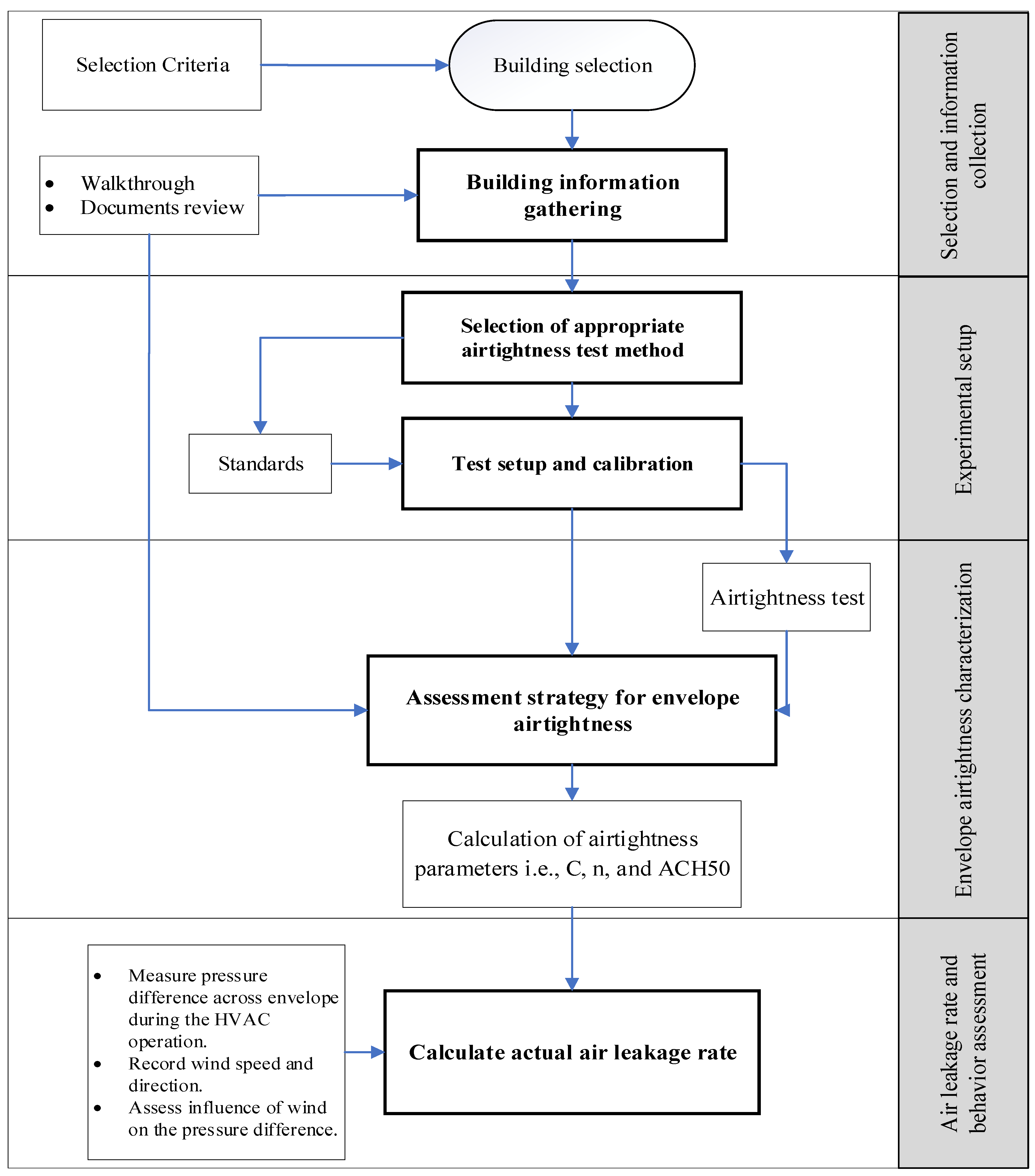
The last phase of the approach is to calculate the actual air leakage rate under normal operating conditions when the HVAC system is running. Based on findings from the literature, which indicate that the air leakage behavior in detached houses is affected by the HVAC system and the suitability of the BDT in measuring airtightness characteristics, it is justifiable to determine the air leakage rate and behavior based on the results of the BDT. The first step is to measure and record the pressure difference across the envelope during the operation of the HVAC system. Simultaneously, a weather station is installed to record wind speed and direction on site. Results from the pressure difference measurements are used to determine the air leakage rate and behavior under HVAC system operation. A schematic diagram describing the main components of the approach used in this study is shown in Figure 2. The next section deals with the implementation of the suggested approach to characterize the air leakage behavior of selected case study houses located in Saudi Arabia. Details of the selected houses, airtightness characterization test, and air leakage determination are also elaborated. The proposed method is climate independent and can be implemented for any air-conditioned detached houses (or similar buildings) where the mechanical system may introduce a positive indoor pressure and hence, alter the pressure differential across the exterior envelope resulting in a unique air leakage behavior.

3. Characterization of Air Leakage Behavior: A Case Study

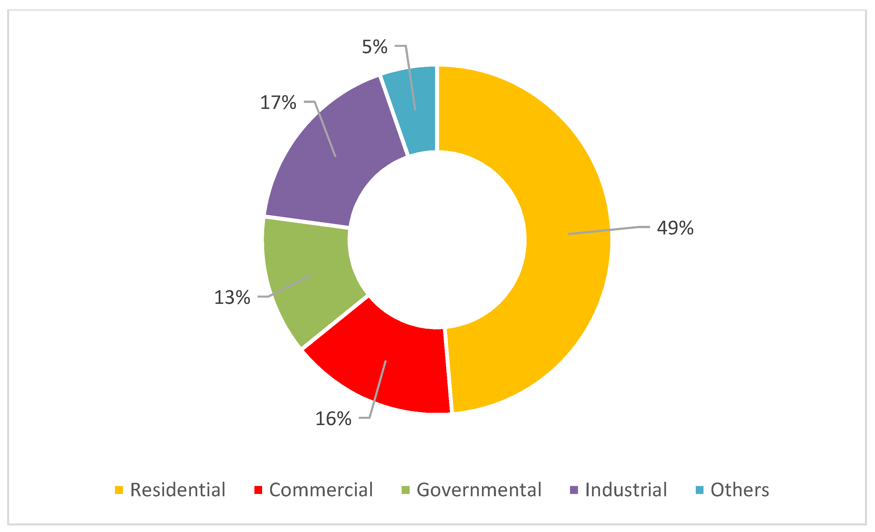
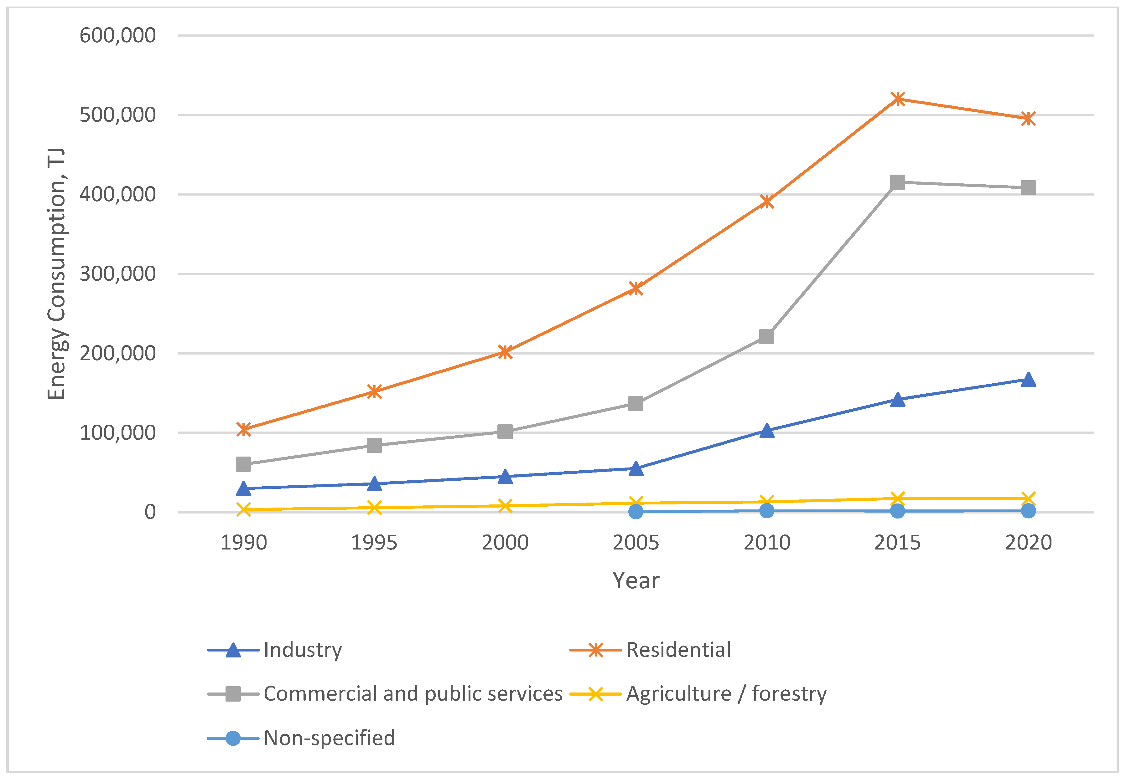
The selected house sample for this study is located in Dhahran, Saudi Arabia, representing one of the harshest climatic conditions. In Saudi Arabia, the building sector is the main target for energy efficiency initiatives implemented by the government because more than 70% of the total energy produced in the kingdom is utilized by this sector [3]. This energy consumption is increasing annually, as displayed in Figure 3. The residential sector was the major consumer of electricity, consuming almost 48.1% of the total in 2017. The breakdown of electricity consumption of the buildings in 2021 (Figure 4) indicates that residential buildings use 49% of the total used electricity [59]. Additionally, according to the IEA [3], energy consumption increased annually between 1990 and 2020, with an average rate of 26.5%, as illustrated in Figure 3. Furthermore, Figure 5 reveals that the rate of increase in energy consumption in the residential sector is the highest among other sectors.
The house sample selection was based on the availability of thermal and physical information and the accessibility of the houses. Furthermore, the selected house type and capacity are typically used in the eastern province of Saudi Arabia. In this study, two houses were selected (House A and House B). Each house is a three-bedroom single-family detached house located in the eastern province of Saudi Arabia, Dhahran. The houses are part of the university’s on-campus faculty housing.
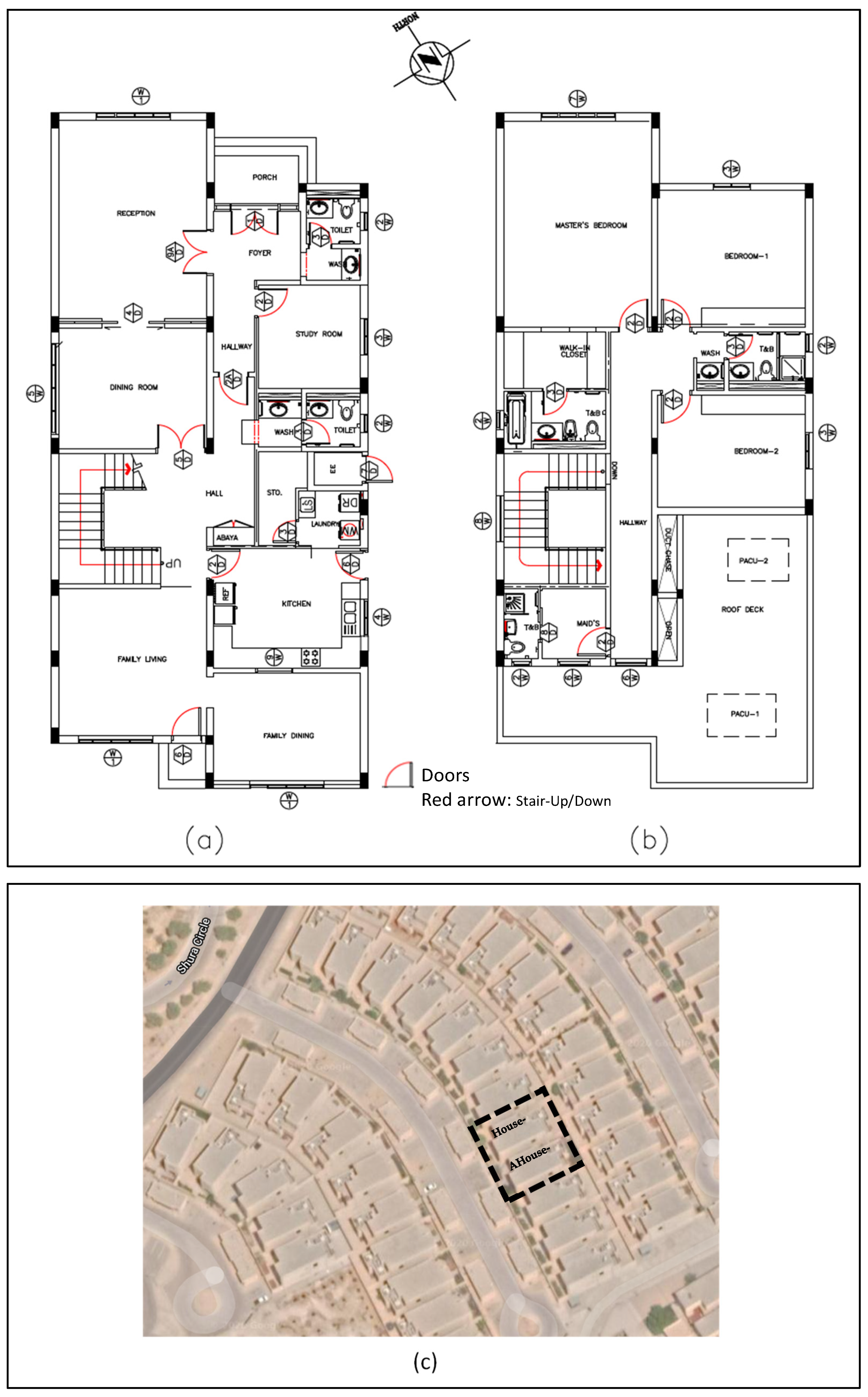
In each house, the ground and first-floor floor areas were 189 and 135 m2, respectively, with a floor height of 3.2 m. Each house is rectangular, as displayed in the house floor plans in Figure 6. The houses are oriented to the southwest at approximately 212° from the north. The first-floor area is less than the ground floor, as part of the space accommodates the HVAC units. The walls and roof of the houses are designed with excellent thermal insulation performance, where the U-values of the exterior walls and roof are 0.466 and 0.539 W/m2, respectively [71]. Table 2 summarizes the envelope components of houses with their layers and thermo-physical features, indicating that the envelope of the houses exhibits excellent thermal properties.
The HVAC system type used in the two houses is a constant-volume (CV) direct expansion package unit, in which a unit serves each floor. The total cooling capacity and supply airflow for the ground floor unit were 40.7 kW (139.8 MBTUH) and 8121.3 m3/h (4780 CFM), respectively, whereas, for the first-floor unit, the cooling capacity was 27.9 kW (95.4 MBTUH) with an airflow rate of 5402.9 m3/h (3180 CFM).

3.1. Experimental System and Setup

The airtightness of the selected houses in this study was measured using the BDT according to the international E779-10 standard [43]. Based on the selected airtightness test method and the selected standard, multiple procedures were set up in the house before starting the test since several parameters were to be checked:
  • All interior doors should be opened during the test to create a uniform pressure within the house.
  • Fireplace and operable dampers should be closed, and HVAC system balancing dampers should not be adjusted.
  • The multiplication of the outdoor/indoor temperature difference (K) with the building height (m) should not exceed 500 m. Because the pressure difference induced by the stack effect will be too large to allow an accurate interpretation of the results.
  • The building volume and wind velocity during the test should not exceed 4000 m3 and 2.0 m/s, respectively.
Furthermore, according to the E779-10 recommendation, the recorded test data correlation coefficient in the pressurization and depressurization modes should not be less than 0.99 for each test scenario.
The typical blower door results determined the airtightness of the entire building and revealed the data plotted in the air leakage graph, which is used to calculate the pressure exponent and the air leakage coefficient defined in Equation (1). Another parameter obtained from the BDT describing the building airtightness is the n50 or ACH50, that is, the air change per hour at a 50 Pa pressure difference. Therefore, this method was used to determine the building airtightness and pressure exponent, and the air leakage coefficient results were obtained.
The n50 value could be obtained using the following expression:
n50 = Q50/V
where Q50 is the airflow rate at a pressure difference of 50 Pa (m3/h), and V is the internal volume of the building (m3).
Based on the conducted walkthrough, the plumbing fixtures were sealed after filling with water as an additional setup step to ensure the accuracy of the test since the houses were not occupied, and empty U-traps and other plumbing fixtures could considerably affect the test results. Additionally, the collected houses’ information from the document reviews and the walkthrough showed that the selected airtightness measurement method is appropriate for the houses’ size and type.
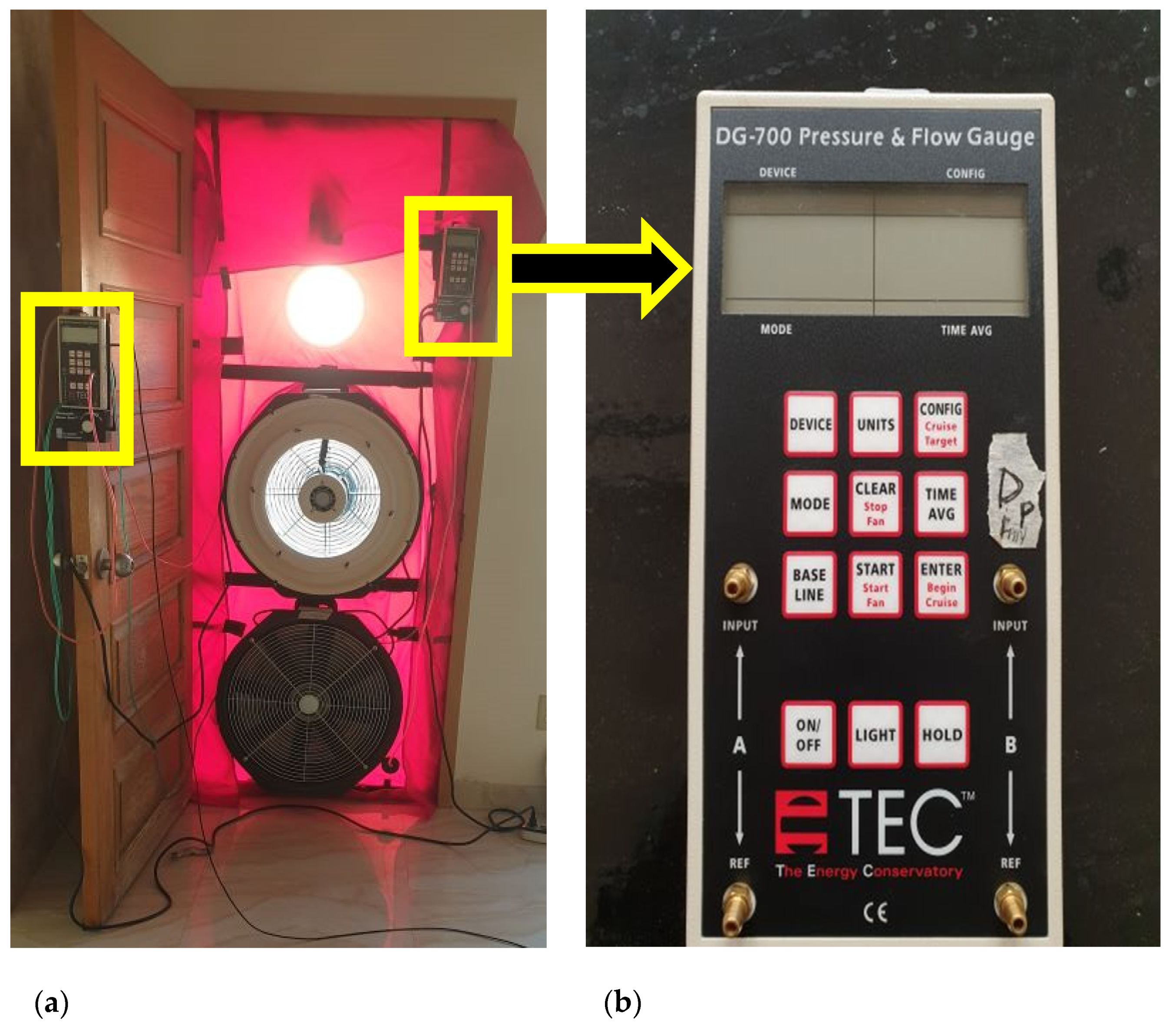
The test system, displayed in Figure 7a, consists of a door assembly with two fans capable of creating the required pressure difference across the envelope and two gauges to measure the pressure and airflow rate. The test has two modes, namely pressurization and depressurization, each of which has a dedicated fan, and both modes were applied for the airtightness measurements. The system was computerized and controlled using TECTITE Express Ver. 4.0 software provided by the system manufacturer. The software allows options to conduct the test automatically, semi-automatically, or manually. Furthermore, the software enables obtaining the results after correcting the input data, such as building baseline pressure, site location altitude, and indoor/outdoor temperature difference. In addition, the control software provides auto-identification of the deviation of results from the selected test standard.
The gauge model DG-700 used, as displayed in Figure 7b, has two distinct pressure channels: one channel for measuring the pressure difference and the other for the fan flow rate. According to the E779 standard requirements, the pressure difference across the envelope should change from 60 to 15 Pa with five Pascal intervals during the airtightness test. Furthermore, the airflow rate required to achieve each pressure difference was measured.

3.2. Envelope Airtightness Characterization

In the selected houses, the space above the ceiling is used as a return plenum for the HVAC system. The return air freely rises as it gains heat from the conditioned zones through the return diffusers, and the return duct moves it to the package unit. Because the return duct is not connected to the return diffusers, every intentional or unintentional opening in the ceiling is a possible air leakage path. Therefore, supply and return diffusers, exterior doors, maintenance openings in the ceiling, lighting fixtures, and intakes of exhaust fans in the kitchen, bathrooms, and laundry area were tested as part of the assessment strategy of the envelope airtightness. All components were sealed from the inside using sealing paper and adhesive plastic tape, as displayed in Figure 8. The effect of envelope characteristics on building airtightness was investigated by conducting several BDT scenarios under different house setups. The results of the different scenarios help to estimate the contribution of the envelope components to the overall building airtightness by repeating the test after sealing the corresponding component and detecting the reduction in the n50 value.
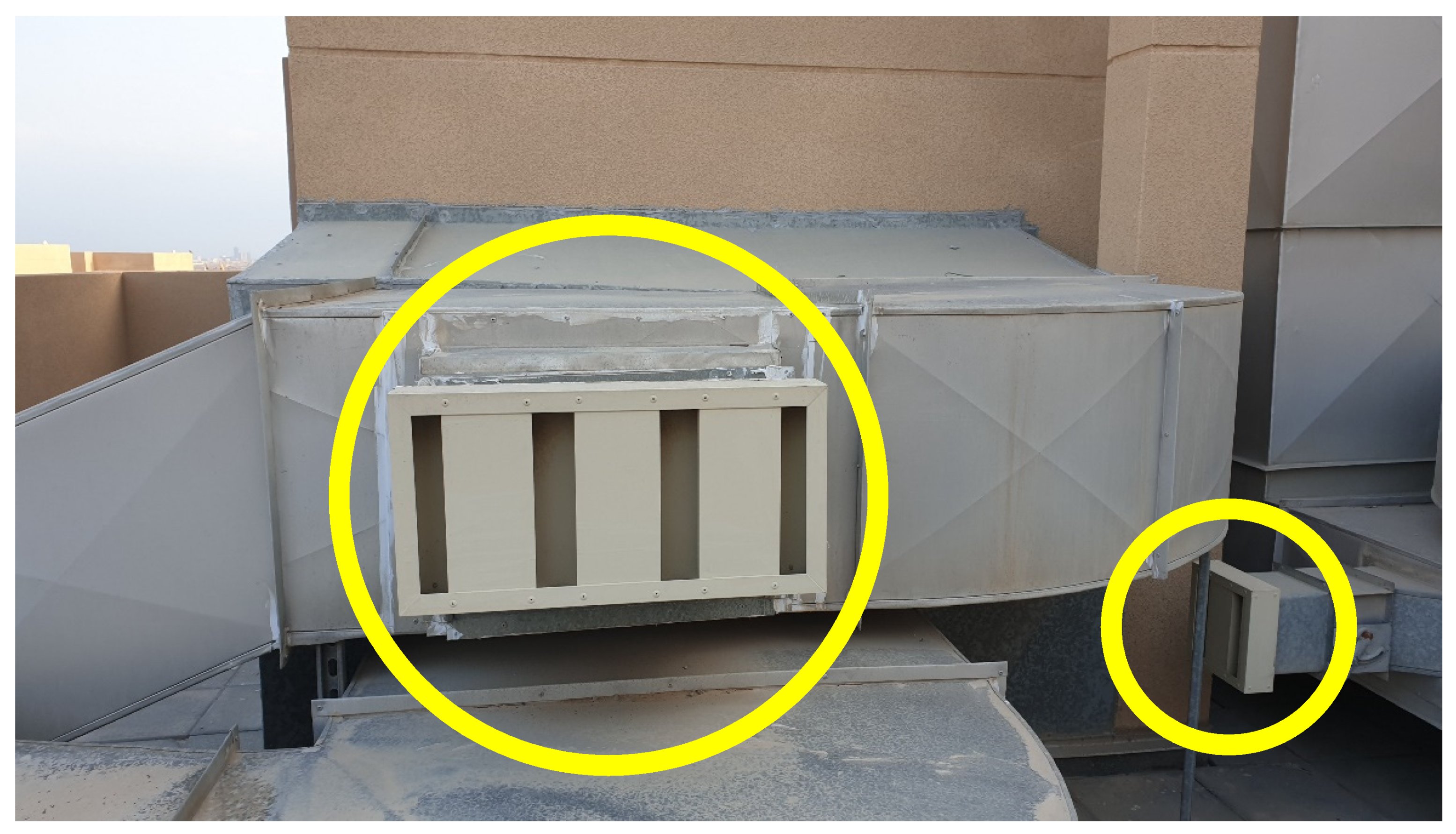
Furthermore, the outdoor air inlet terminals in the return ducts near the package units were sealed during the airtightness test scenarios to eliminate any air leakage through them, as illustrated in Figure 9. Notably, in House B, the dampers in both outdoor inlet terminals were closed.

3.3. Estimation of Air Leakage Rate

The calculation of the actual air leakage rate is crucial to understand the air leakage behavior of the selected houses. It mainly determines the air change rate of a building under specific conditions [9]. Therefore, the BDT results were utilized to calculate the air leakage rate using the relationship between the airflow rate and the pressure difference across the envelope in Equation (1).
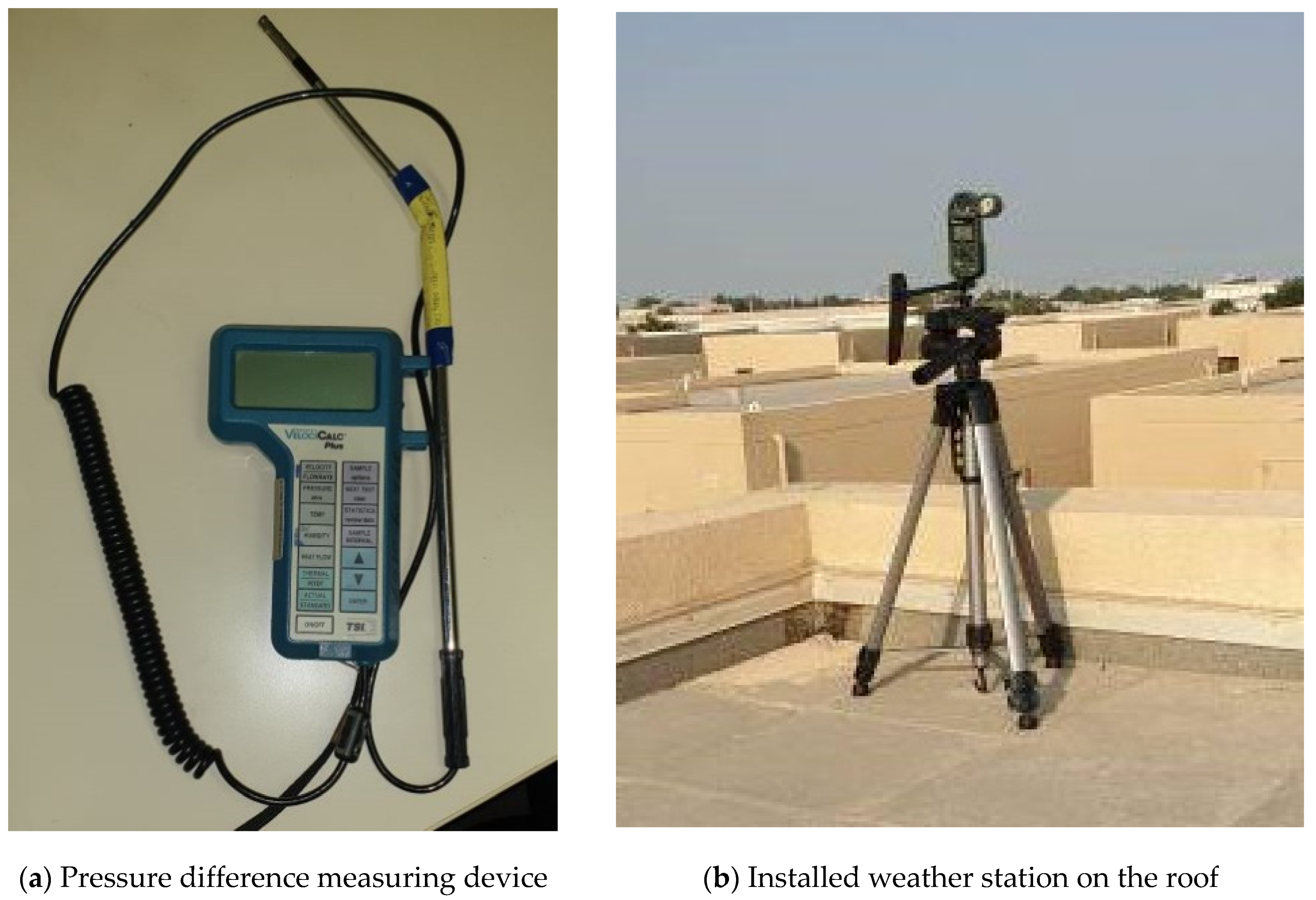
The air leakage behavior in centrally air-conditioned detached houses depends mainly on the pressure difference induced by the operation of the HVAC. Therefore, a pressure-measuring device was placed to measure and record the pressure difference across the envelope with five-minute intervals, as illustrated in Figure 10, to determine the normal operating pressure of the building, which can be used in Equation (1). The pressure device was located on the north, west, and east sides. The HVAC system was running during the measurement period to mimic the house’s operating conditions, as it was conditioned with a constant air HVAC system type. In House A, the pressure difference was recorded for six days with two days on each side of the building, whereas in House B, it was recorded for three days only across the north side of the building because it contained most of the openings on the longest side.
Simultaneously, as displayed in Figure 10, a weather station was placed on the houses’ roofs to calculate and record the wind velocity and direction. These weather data were used to investigate the relationship between wind velocity and direction variation with the pressure difference across the envelope. It is essential to highlight that the developed method for air leakage estimation is applicable for centrally air-conditioned detached houses.

4. Results and Discussion

4.1. Characterization of Envelope Airtightness

Table 3 and Table 4 present the airtightness test results under various setup scenarios for House A and House B, respectively. The results obtained in Test-1 could be considered a base case because the houses were prepared according to the E779-10 standard. In this base case, the average air change rates were 6.58 and 7.04 ACH50, respectively.
Test-5, in which only supply diffusers are sealed, can be considered a base for comparing the tested houses because it simulates the operation condition of the house when the cooling system is running. Accordingly, House A is more airtight than House B because it achieved lower ACH50 results in Test-1 and Test-5.
Despite the similarity between the two houses and test procedures, a noticeable difference exists in the measured airtightness. This difference can be attributed to the various conditions of the HVAC terminals, but primarily to the occupants’ interference in altering the enclosure components, which affected their airtightness characteristics and thereby affected the overall building airtightness.
In Saudi Arabia, no standard reference values have been proposed for building airtightness because of the absence of research on building airtightness and air infiltration. Therefore, the airtightness results for 2080 North American houses, referenced in ASHRAE [72], were reviewed. In this study, the airtightness of most measured houses is between 8 and 12 ACH rates under a 50-Pa pressure difference. Based on the Test-1 results of the tested houses, the measured ACH50 values were within the average range compared with those of the American houses [72] that were reviewed.
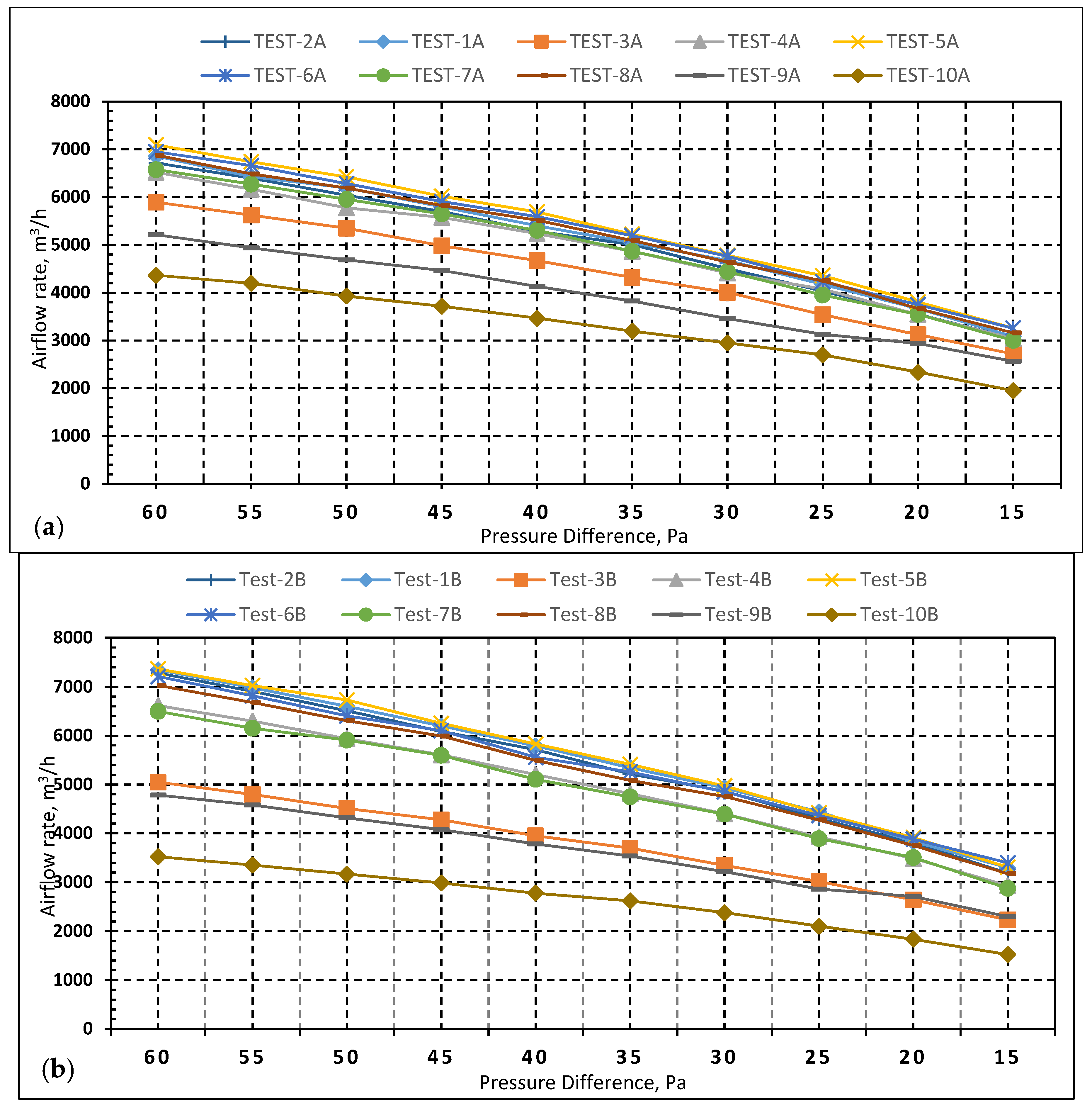
Table 5 presents the effect of each component on the air leakage for both houses when considering the Test-1 scenario as a reference. For House A, the exhaust fans contribute 0.11 ACH50 to the building leakage, representing the difference between Test-1A and Test-2A. Furthermore, the results of Test-5A, Test-6A, and Test-8A after sealing the HVAC system partially with and without the exhaust fans were higher than the base case scenario in which no tested components were sealed, as displayed in Figure 11a and Table 3. Additionally, the difference between the pressurization and depressurization tests decreased in all scenarios where the exhaust fans were sealed, as presented in Table 3.
For the Test-5 scenario, the same phenomenon occurred for the two houses, as displayed in Figure 11 and Table 4, which revealed a behavior similarity in the air leakage path in the sample houses. Moreover, the reduction between Test-3A and Test-10A represents the share of the building leakage attributable to maintenance openings, lighting, and doors, which is 0.72 and 1.89 ACH50 in House A and House B, respectively.
HVAC terminals were the highest contributors to House A’s air leakage with 0.83 ACH50, whereas the maintenance and lighting ceiling openings were the highest in House B with 1.89 ACH50. The highest average ACH50 in House A was 6.98 when supply diffusers and exhaust fans were sealed (Test-7A), whereas, in House B, the highest average ACH50 was obtained when only supply diffusers were sealed (Test-5B), which was 7.12 ACH50. This outcome indicated that some air leakage paths, particularly maintenance opening covers and exhaust fan louvers, exhibited erratic behavior depending on the applied pressure difference and the availability of other air leakage paths. The behavior of the exhaust fans could be detected from the high value of ACH50 under the pressurization mode obtained in scenarios when exhaust fans were not sealed. Comparing the Test-10A and Test-10B results revealed that the openings with variable behavior in House B contribute more to the air leakage than those in House A.

4.2. Estimation of Air Leakage

The pressure exponent (n) values and the air leakage coefficient (C) obtained from Test-1 and Test-5 in the two houses were used to calculate the air leakage flow rate in the two houses. As mentioned, the Test-1 scenario was selected because it represents the base case when the house is prepared according to the E779-10 standard. At the same time, Test-5 represents the normal operating conditions of the houses during the cooling system operation.
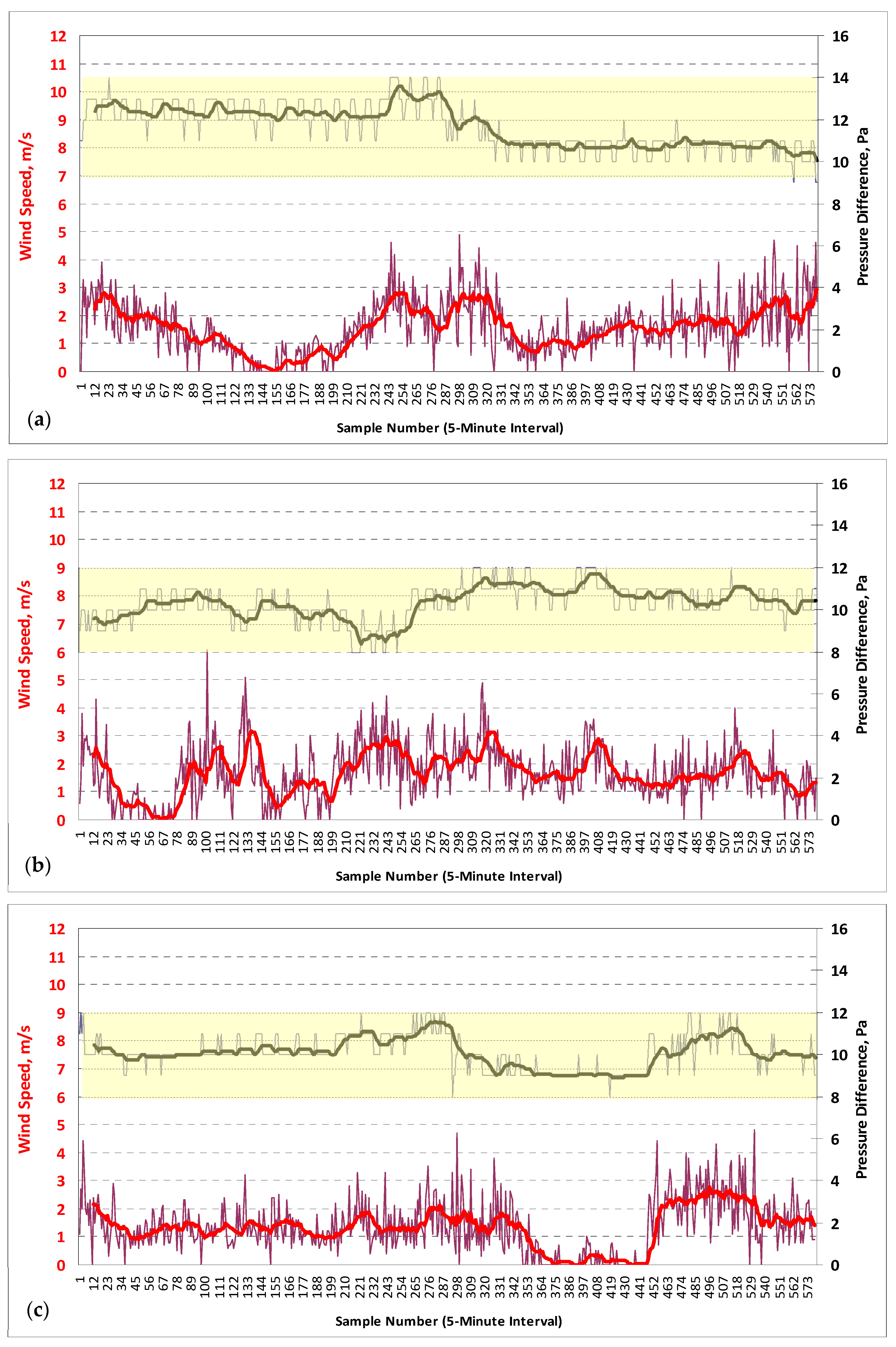
In House A, the measured pressure difference across the envelope fluctuated between 9–12 Pa with an average value of 11 Pa. In House B, the pressure difference range was 7–10 Pa, and the average pressure difference was 9 Pa, as shown in Figure 12. Although the tested houses are similar, the marginal difference in the pressure across the envelope can be attributed to the variations in the envelope and HVAC system characteristics, particularly the fan operation, which affects the resulting mechanically induced pressure.
Although the recorded wind exhibited a wide velocity range with different predominant directions, the pressure difference across the envelope in the tested houses was always positive throughout the measurement period, as presented in Table 6 and Figure 12. This is because the predominant effect of the mechanically induced pressure marginalized the wind pressure on the building surfaces, particularly with the CV AC type, rendering the air leakage behavior dependent on the AC system operation and condition. Therefore, such positive pressure is likely to be encountered throughout the year for such buildings, especially when considering the low height of such buildings and the shielding effect of the surroundings.
Moreover, the obtained positive pressure difference indicates that both houses are under exfiltration during the operation of the HVAC system, which could be considered a massive source of energy wastage because the cooling system compensated for the exfiltrated conditioned air with unconditioned fresh air, increasing the energy required for cooling, as demonstrated in Figure 13. In addition, the aforementioned use of the ceiling space as a return plenum increases the energy loss by exfiltration because the behavior of all envelope openings above the ceiling is unknown, in addition to the inherent inaccessibility. However, with further investigation, this high airflow rate can eliminate the requirement for a fresh air system because the compensation of fresh air through the HVAC system could satisfy the ventilation requirement of the houses.
Table 7 lists the values of the air leakage coefficient C, pressure exponent n, air leakage flow rate, and air change rate for the sample houses. The obtained air leakage rates represent the regression relationship results obtained from the leakage graph generated from the BDT data. Although the ACH50 of House A was lower than House B, as displayed in Table 3 and Table 4, the calculated air leakage rate was higher in House A because of the high-pressure difference in House A, which confirmed that the air leakage behavior of the selected houses depended on the operation and condition of the HVAC system.

5. Conclusions

With the increase in the energy consumed by buildings, the currently developed standards have become more restrictive regarding energy-saving expectations. Therefore, assessing airtightness and air leakage is vital in meeting these emerging energy requirements for sustainable buildings. This study investigated the air leakage behavior of centrally air-conditioned houses. A sample case study, located in Saudi Arabia, was selected to apply the developed methodology. Two typical houses in Dhahran were selected and tested for airtightness under a standard pressure difference (50 Pa). The measurements revealed that both houses exhibit an almost similar air change rate (i.e., 6.58 and 7.04 h−1) under 50 Pa, which is comparable to most reported US houses in the ASHRAE standard. In addition, the air leakage contribution of envelope elements such as exhaust fans, windows, doors, lighting and maintenance ceiling openings, and cooling system air terminals to the overall airtightness level was investigated. The results revealed considerable differences in the various elements’ contribution to the total building airtightness depending on the applied pressure and the availability of other air leakage elements. In House A, the HVAC system terminals, the supply and return diffusers, contributed 35% of the total contribution of the tested components. In House B, 52% of the total contribution of the tested components was caused by the maintenance and lighting openings in the false ceiling.
Both houses’ air leakage flow rates were estimated using the BDT results and the measured pressure across the envelope during normal operating conditions. The use of the constant volume HVAC system induced a positive internal pressure relative to the prevailing wind and stack-induced pressure resulting in a net air exfiltration in both houses of approximately 2.90 and 2.51 ACH. Therefore, the HVAC system will have to compensate for the exfiltrated air with unconditioned outdoor air resulting in additional energy consumption to overcome the additional heat gain. Therefore, envelope air leakage characteristics considerably influence building energy performance, even in the absence of air infiltration. Furthermore, the results show that accurate air infiltration estimation is essential for the reliability of energy performance assessment.
The effect of envelope air leakage characteristics on airtightness and the resulting air leakage, particularly in detached houses, should be investigated in detail. This would allow more information and data about air leakage of various building types and the development of national standards that are currently lacking. In addition, the feasibility of the approach followed by applying different test scenarios on sample houses that match the local residential trend was examined. Moreover, the study highlighted several aspects to consider when investigating a large-scale sample of houses for airtightness and energy performance estimation, such as the induced pressure by the HVAC relative to the wind and stack effect and the changing behavior of the air leakage paths based on the pressure difference and the availability of the other air leakage paths. Further research is needed to investigate the airtightness behavior of other building types in Saudi Arabia, which is crucial for assessing and improving building performance and design.

Author Contributions

Conceptualization, M.A.M., I.M.B. and A.A.A.; Methodology, M.A.M., I.M.B. and A.A.A.; Software, M.A.M. and A.A.A.; Validation, M.A.M. and A.A.A.; Formal analysis, M.A.M., I.M.B. and A.A.A.; Investigation, M.A.M., I.M.B. and A.A.A.; Resources, I.M.B. and A.A.A.; Data curation, M.A.M. and A.A.A.; Writing—original draft preparation, M.A.M., I.M.B. and A.A.A.; Writing—review and editing, M.A.M. and A.A.A.; Visualization, M.A.M. and A.A.A.; Supervision, I.M.B. and A.A.A.; Project administration, I.M.B. and A.A.A.; All authors have read and agreed to the published version of the manuscript.

Funding

This research received no external funding.

Data Availability Statement

Data sharing not applicable.

Acknowledgments

The authors would like to acknowledge the support of King Fahd University of Petroleum and Minerals (KFUPM) for using its laboratory and research facilities.

Conflicts of Interest

The authors declare no conflict of interest.

References

  1. Kölsch, B.; Walker, I.S.; Schiricke, B.; Delp, W.W.; Hoffschmidt, B. Quantification of air leakage paths: A comparison of airflow and acoustic measurements. Int. J. Vent. 2021, 1–21. [Google Scholar] [CrossRef]
  2. IEA. Global CO2 Emissions from the Operation of Buildings Rebounded in 2021 to above 2019 Levels. 2022. Available online: https://www.iea.org/reports/buildings# (accessed on 26 February 2023).
  3. International Energy Agency. World Energy Outlook 2019; IEA: Paris, France, 2019; Available online: https://www.iea.org/reports/world-energy-outlook-2019 (accessed on 1 June 2020).
  4. Abuhussain, M.A.; Chow, D.H.C.; Sharples, S. Assessing the adaptability of the Saudi residential building’s energy code for future climate change scenarios. In Proceedings of the 34th International Conference on Passive and Low Energy Architecture, Hong Kong, China, 10–12 December 2018. [Google Scholar]
  5. Dubey, K.; Nicholas, H.; Moncef, K. Evaluating Building Energy Efficiency Investment Options for Saudi Arabia, Riyadh, Kapsarc (2016). pp. 1–64. Available online: https://www.kapsarc.org/wp-content/uploads/2016/10/KS-1655-DP049A-Evaluating-Building-Energy-Efficiency-Investment-Options-for-SA_web.pdf (accessed on 26 February 2023).
  6. Felimban, A.; Prieto, A.; Knaack, U.; Klein, T.; Qaffas, Y. Residential Buildings in Jeddah, Saudi Arabia. Buildings 2019, 9, 163. [Google Scholar] [CrossRef] [Green Version]
  7. Esmaeil, K.K.; Alshitawi, M.S.; Almasri, R.A. Analysis of energy consumption pattern in Saudi Arabia’s residential buildings with specific reference to Qassim region. Energy Effic. 2019, 12, 2123–2145. [Google Scholar] [CrossRef]
  8. Almasri, R.A.; Almarshoud, A.F.; Omar, H.M.; Esmaeil, K.K.; Alshitawi, M. Exergy and Economic Analysis of Energy Consumption in the Residential Sector of the Qassim Region in the Kingdom of Saudi Arabia. Sustainability 2020, 12, 2606. [Google Scholar] [CrossRef] [Green Version]
  9. Younes, C.; Shdid, C.A.; Bitsuamlak, G. Air infiltration through building envelopes: A review. J. Build. Phys. 2011, 35, 267–302. [Google Scholar] [CrossRef]
  10. Gillott, M.C.; Loveday, D.L.; White, J.; Wood, C.J.; Chmutina, K.; Vadodaria, K. Improving the airtightness in an existing UK dwelling: The challenges, the measures and their effectiveness. Build. Environ. 2016, 95, 227–239. [Google Scholar] [CrossRef] [Green Version]
  11. Johnston, D.K.; Miles-Shenton, D.; Bell, M.; Wingfield, J. Airtightness of Buildings—Towards Higher Performance: Final Report—Domestic Sector Airtightness; Department for Communities and Local Government: London, UK, 2011.
  12. Zmeureanu, R. Cost-Effectiveness of Increasing Airtightness of Houses. J. Arch. Eng. 2000, 6, 87–90. [Google Scholar] [CrossRef]
  13. Cardoso, V.E.M.; Pereira, P.F.; Ramos, N.M.M.; Almeida, R.M.S.F. The Impacts of Air Leakage Paths and Airtightness Levels on Air Change Rates. Buildings 2020, 10, 55. [Google Scholar] [CrossRef] [Green Version]
  14. Emmerich, S.J.; Persily, A.K. Energy impacts of infiltration and ventilation in US office buildings using multi-zone airflow simulation. Proc. IAQ Energy 1998, 98, 191–206. [Google Scholar]
  15. Osipov, A.; Meesb, P.; Vermeif, G. Low-Frequency Airborne Sound Transmission through Single Partitions in Buildings. Appl. Acoust. 1997, 52, 3. [Google Scholar] [CrossRef]
  16. Persily, A. Repeatability and accuracy of pressurization testing. In Proceedings of the ASHRAE/DOE Conference on Thermal Performance of the Exterior Envelope of Buildings, Las Vegas, NV, USA, 6–9 December 1982. [Google Scholar]
  17. ASTM E779-10; Standard Test Method for Determining Air Leakage Rate by Fan Pressurization. American Society for Testing and Materials: Philadelphia, PA, USA, 2010.
  18. Sherman, M.H.; Chan, R. Building Airtightness: Research and Practice; Lawrence Berkeley National Laboratory Report No. LBNL-53356; Building Technology and Urban Systems Division: Berkeley, CA, USA, 2004.
  19. Jokisalo, J.; Kalamees, T.; Kurnitski, J.; Eskola, L.; Jokiranta, K.; Vinha, J. A Comparison of Measured and Simulated Air Pressure Conditions of a Detached House in a Cold Climate. J. Build. Phys. 2008, 32, 67–89. [Google Scholar] [CrossRef]
  20. Prignon, M.; Van Moeseke, G. Factors influencing airtightness and airtightness predictive models: A literature review. Energy Build. 2017, 146, 87–97. [Google Scholar] [CrossRef]
  21. Sherman, M.H. Estimation of infiltration from leakage and climate indicators. Energy Build. 1987, 10, 81–86. [Google Scholar] [CrossRef] [Green Version]
  22. Bramiana, C.; Entrop, A.G.; Halman, J.I.M. Relationships between Building Characteristics and Airtightness of Dutch Dwellings. Energy Procedia 2016, 96, 580–591. [Google Scholar] [CrossRef] [Green Version]
  23. Sfakianaki, A.; Pavlou, K.; Santamouris, M.; Livada, I.; Assimakopoulos, M.-N.; Mantas, P.; Christakopoulos, A. Air tightness measurements of residential houses in Athens, Greece. Build. Environ. 2008, 43, 398–405. [Google Scholar] [CrossRef]
  24. Feijó-Muñoz, J.; Pardal, C.; Echarri, V.; Fernández-Agüera, J.; Assirgo de Larriva, R.; Montesdeoca Calderín, M.; Poza-Casado, I.; Padilla-Marcos, M.; Meiss, A. Energy impact of the air infiltration in residential buildings in the Mediterranean area of Spain and the Canary islands. Energy Build. 2019, 188–189, 226–238. [Google Scholar] [CrossRef]
  25. Dickerhoff, D.J.; Grimsrud, D.T.; Lipschutz, R.D. Component Leakage Testing in Residential Buildings; Ernest Orlando Lawrence Berkeley National Laboratory: Berkeley, CA, USA, 1982.
  26. Etheridge, D.W. Air leakage characteristics of houses—A new approach. Build. Serv. Eng. Res. Technol. 1984, 5, 32–36. [Google Scholar] [CrossRef]
  27. Gadsby, K.J.; Harrje, D.T. Fan pressurization of building: Standards, calibration, and field experience. Build. Eng. 1985, 91, 95–104. [Google Scholar]
  28. Persily, A.K.; Grot, R.A. Accuracy in pressurization data analysis. ASHRAE Trans. 1985, 91, 105–119. [Google Scholar]
  29. Brinks, P.; Kornadt, O.; Oly, R. Air infiltration assessment for industrial buildings. Energy Build. 2015, 86, 663–676. [Google Scholar] [CrossRef]
  30. Kempton, L.; Daly, D.; Kokogiannakis, G.; Dewsbury, M. A rapid review of the impact of increasing airtightness on indoor air quality. J. Build. Eng. 2022, 57, 104798. [Google Scholar] [CrossRef]
  31. Walker, I.S.; Wilson, D.J.; Sherman, M.H. A comparison of the power law to quadratic formulations for air infiltration calculations. Energy Build. 1998, 27, 293–299. [Google Scholar] [CrossRef] [Green Version]
  32. Sherman, M. A Power-Law Formulation of Laminar Flow in Short Pipes. J. Fluids Eng. 1992, 114, 601–605. [Google Scholar] [CrossRef]
  33. Kukadia, V.; Upton, S. Ensuring Good Indoor Air Quality in Buildings; BRE Trust: Watford, UK, 2019. [Google Scholar]
  34. Logue, J.M.; Sherman, M.H.; Walker, I.S.; Singer, B.C. Energy impacts of envelope tightening and mechanical ventilation for the U.S. residential sector. Energy Build. 2013, 65, 281–291. [Google Scholar] [CrossRef] [Green Version]
  35. Lozinsky, C.H.; Touchie, M.F. Improving energy model calibration of multi-unit residential buildings through component air infiltration testing. Build. Environ. 2018, 134, 218–229. [Google Scholar] [CrossRef]
  36. Emmerich, S.J.; Persily, A.K.; Mcdowell, T.P. Impact of Infiltration on Heating and Cooling Loads in U.S. Office Buildings. In Proceedings of the 26th AIVC Conference Ventilation in Relation to the Energy Performance of Buildings, Brussels, Belgium, 21–23 September 2005. [Google Scholar]
  37. Genge, C. Controlling air leakage int tall buildings. ASHRAE J. 2009, 51, 50–60. [Google Scholar]
  38. ASTM E741–00; Standard Test Method for Determining Air Change in a Single Zone by Means of a Tracer Gas Dilution. American Society for Testing and Materials: West Conshohocken, PA, USA, 2000.
  39. Zheng, X.; Cooper, E.; Gillott, M.; Wood, C. A practical review of alternatives to the steady pressurisation method for de-termining building airtightness. Renew. Sustain. Energy Rev. 2020, 132, 110049. [Google Scholar] [CrossRef]
  40. Walker, I.S.; Sherman, M.H.; Joh, J.; Chan, W.R. Applying large datasets to developing a better understanding of air leakage measurement in homes. Int. J. Vent. 2013, 11, 323–338. [Google Scholar] [CrossRef]
  41. Jokisalo, J.; Kurnitski, J.; Korpi, M.; Kalamees, T.; Vinha, J. Building leakage, infiltration, and energy performance analyses for Finnish detached houses. Build. Environ. 2009, 44, 377–387. [Google Scholar] [CrossRef]
  42. Poza-Casado, I.; Cardoso, V.E.M.; Almeida, R.M.S.F.; Meiss, A.; Ramos, N.M.M.; Padilla-Marcos, M.Á. Residential buildings airtightness frameworks: A review on the main databases and setups in Europe and North America. Build. Environ. 2020, 183, 107221. [Google Scholar] [CrossRef]
  43. Buning, L.; Store, I.S.O. Thermal performance of buildings—Determination of air permeability of buildings—Fan pressurization method. Internaional Stand. ISO 9972 2006, 2006, 28. [Google Scholar] [CrossRef]
  44. ASTM E779-19; Standard Test Method for Determining Air Leakage Rate by Fan Pressurization. ASTM International: West Conshohocken, PA, USA, 2010; Volume i, pp. 1–11. [CrossRef]
  45. Delmotte, C. Airtightness of Buildings-Considerations regarding the Zero-Flow Pressure and the Weighted Line of Organic Correlation. In Proceedings of the 38th AIVC Conference “Ventilating Healthy Low-Energy Buildings”, Nottingham, UK, 13–14 September 2017. [Google Scholar]
  46. Carrié, F.R.; Leprince, V. Uncertainties in building pressurisation tests due to steady wind. Energy Build. 2016, 116, 656–665. [Google Scholar] [CrossRef]
  47. Hult, E.L.; Sherman, M.H. Estimates of Uncertainty in Multi-Zone Air Leakage Measurements. Int. J. Vent. 2014, 12, 359–368. [Google Scholar] [CrossRef]
  48. Delmotte, C. Airtightness of buildings-Calculation of combined standard uncertainty. In Proceedings of the 34th AIVC Conference “Energy Conservation Technologies for Mitigation and Adaptation in the Built Environment: The Role of Ventilation Strategies and Smart Materials”, Athens, Greece, 25–26 September 2013. [Google Scholar]
  49. Delmotte, C.; Laverge, J. Interlaboratory tests for the determination of repeatability and reproducibility of buildings airtightness measurements. In Proceedings of the 2nd AIVC Conference “Towards Optimal Airtightness Performance”, Brussels, Belgium, 12–13 October 2011. [Google Scholar]
  50. Persily, A.K. Air Flow Calibration of Building Pressurization Devices; US Department of Commerce, National Bureau of Standards: Washington, DC, USA, 1984.
  51. Modera, M.P.; Wilson, D.J. The effects of wind on residential building leakage measurements. In Air Change Rate and Airtightness in Buildings; ASTM International: West Conshohocken, PA, USA, 1990. [Google Scholar]
  52. Siren, K. A modification of the power-law equation to account for large scale wind turbulence. In Proceedings of the 18th AIVC Conference “Ventilation and Cooling”, Athens, Greece, 23–24 September 1997; Volume 2, pp. 557–566. [Google Scholar]
  53. Sherman, M.; Palmiter, L. Uncertainties in Fan Pressurization Measurements. In Airflow Performance of Building Envelopes, Components, and Systems; ASTM International: West Conshohocken, PA, USA, 1995; pp. 266–283. [Google Scholar] [CrossRef]
  54. Love, J.; Wingfield, J.; Smith, A.; Biddulph, P.; Oreszczyn, T.; Lowe, R.; Elwell, C. ‘Hitting the target and missing the point’: Analysis of air permeability data for new UK dwellings and what it reveals about the testing procedure. Energy Build. 2017, 155, 88–97. [Google Scholar] [CrossRef]
  55. Mélois, A.B.; Moujalled, B.; Guyot, G.; Leprince, V. Improving building envelope knowledge from analysis of 219,000 certified on-site air leakage measurements in France. Build. Environ. 2019, 159, 106145. [Google Scholar] [CrossRef] [Green Version]
  56. Kurnitski, J.; Saari, A.; Kalamees, T.; Vuolle, M.; Niemelä, J.; Tark, T. Cost Optimal and Nearly Zero (nZEB) Energy Performance Calculations for Residential Buildings with the Federation of European Heating, Ventilation and Air Conditioning Association Definition for nZEB National Implementation. Energy Build. 2011, 43, 3279–3288. [Google Scholar] [CrossRef]
  57. Hassid, S.; Santamouris, M.; Papanikolaou, N.; Linardi, A.; Klitsikas, N.; Georgakis, C.; Assimakopoulos, D. The effect of the Athens heat island on air conditioning load. Energy Build. 2000, 32, 131–141. [Google Scholar] [CrossRef]
  58. Ren, Z.; Chen, D. Estimation of air infiltration for Australian housing energy analysis. J. Build. Phys. 2014, 39, 69–96. [Google Scholar] [CrossRef]
  59. Water & Electricity Regulatory Authority (WERA), Energy Sales by Consumption Categories and Year, 2023. Available online: https://wera.gov.sa/Statistics/NRDetailsC1?CategoryId=6&SheetsId=20 (accessed on 10 February 2023).
  60. Heim, D.; Miszczuk, A. Modelling building infiltration using the airflow network model approach calibrated by air-tightness test results and leak detection. Build. Serv. Eng. Res. Technol. 2020, 41, 681–693. [Google Scholar] [CrossRef]
  61. Mortensen, L.H.; Bergsøe, N.C. Air tightness measurements in older Danish single-family houses. Energy Procedia 2017, 132, 825–830. [Google Scholar] [CrossRef]
  62. Alfano, F.D.A.; Dell’Isola, M.; Ficco, G.; Tassini, F. Experimental analysis of air tightness in Mediterranean buildings using the fan pressurization method. Build. Environ. 2012, 53, 16–25. [Google Scholar] [CrossRef]
  63. Šadauskienė, J.; Seduikyte, L.; Paukštys, V.; Banionis, K.; Gailius, A. The role of air tightness in assessment of building energy performance: Case study of Lithuania. Energy Sustain. Dev. 2016, 32, 31–39. [Google Scholar] [CrossRef]
  64. Kalamees, T. Air tightness and air leakages of new lightweight single-family detached houses in Estonia. Build. Environ. 2007, 42, 2369–2377. [Google Scholar] [CrossRef]
  65. Han, G.; Srebric, J.; Enache-Pommer, E. Different modeling strategies of infiltration rates for an office building to improve accuracy of building energy simulations. Energy Build. 2015, 86, 288–295. [Google Scholar] [CrossRef]
  66. Montoya, M.I.; Pastor, E.; Carrié, F.R.; Guyot, G.; Planas, E. Air leakage in Catalan dwellings: Developing an airtightness model and leakage airflow predictions. Build. Environ. 2010, 45, 1458–1469. [Google Scholar] [CrossRef] [Green Version]
  67. Feijó-Muñoz, J.; González-Lezcano, R.A.; Poza-Casado, I.; Padilla-Marcos, M.; Meiss, A. Airtightness of residential buildings in the Continental area of Spain. Build. Environ. 2018, 148, 299–308. [Google Scholar] [CrossRef]
  68. Bracke, W.; Laverge, J.; Bossche, N.V.D.; Janssens, A. Durability and Measurement Uncertainty of Airtightness in Extremely Airtight Dwellings. Int. J. Vent. 2016, 14, 383–394. [Google Scholar] [CrossRef] [Green Version]
  69. Erhorn-Kluttig, H.; Erhorn, H.; Lahmidi, H. Airtightness requirements for high performance building envelopes. In Proceedings of the AIVC 30th Conference: Trends in High Performance Buildings and the Role of Ventilation, Berlin, Germany, 1–2 October 2009. [Google Scholar]
  70. Papaglastra, M.; Leivada, I.; Sfakianaki, K.; Carrié, F.R.; Santamouris, M. International comparison of envelope airtightness measurements. In Proceedings of the 3rd European Blower Door Symposium, Kassel, Germany, 30–31 May 2008; pp. 30–31. [Google Scholar]
  71. Syed, A.T.; Abdo, A.A. A Moder of Near-Zero Energy Home (nZEH) Using Passive Design Strategies and PV Technology in Hot Climates. J. Green Build. 2016, 11, 38–70. [Google Scholar] [CrossRef] [Green Version]
  72. Sherman, M.H.; Dickerhoff, D.J. Air-tightness of US dwellings. Trans. -Am. Soc. Heat. Refrig. Air Cond. Eng. 1998, 104, 1359–1367. [Google Scholar]
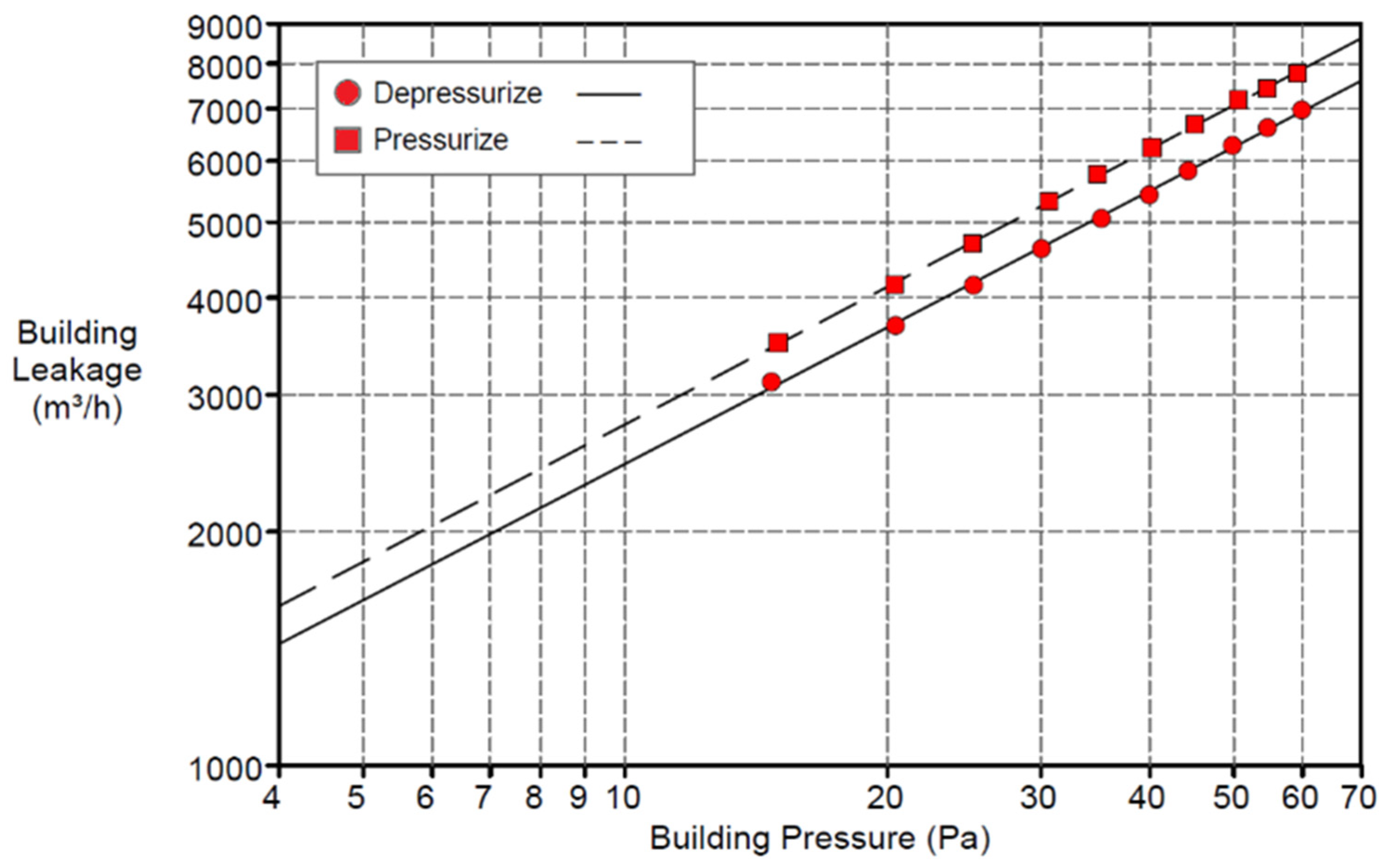
Figure 1. Example air leakage graph using the blower door test.
Buildings 13 00660 g001
Figure 2. The approach for characterization of air leakage behavior.
Buildings 13 00660 g002
Figure 3. The annual increase in domestic energy use in Saudi Arabia [3,5].
Buildings 13 00660 g003
Figure 4. 2021 electricity consumption breakdown in Saudi Arabia [71].
Buildings 13 00660 g004
Figure 5. Electricity end-use consumption by sector between 1990–2020 [3].
Buildings 13 00660 g005
Figure 6. (a) Ground floor plan, (b) first-floor plan, and (c) buildings’ surroundings.
Buildings 13 00660 g006
Figure 7. Used (a) BDT assembly and (b) pressure gauges.
Buildings 13 00660 g007
Figure 8. Possible air leakage paths in the ceiling. (shown by arrows).
Buildings 13 00660 g008
Figure 9. HVAC outdoor air inlets. (shown within circles).
Buildings 13 00660 g009
Figure 10. Used pressure differential equipment and weather station.
Buildings 13 00660 g010
Figure 11. Air leakage graphs (a) House A, (b) House B.
Buildings 13 00660 g011
Figure 12. Variation of pressure difference across the envelope and wind speed. (a) House A; (b) and (c) House B. (red: trend line for wind speed; green: trend line for pressure difference; yellow zone: pressure difference range).
Buildings 13 00660 g012
Figure 13. Air leakage behavior.
Buildings 13 00660 g013
Table 1. Envelope component contribution to air infiltration in residential buildings [25].
Building ComponentPercentage RangeAverage Contribution
Walls18–50%35%
Cooling systems3–28%18%
Fireplace0–30%12%
Windows and doors6–22%15%
Vents2–12%5%
Others≤1%
Table 2. Envelope components details [71].
Envelope ComponentLayers: Outside to InsideU-Value
W/(m2·K)
External walls16 mm Plaster (Dense) + 100 mm Concrete Block (Medium) + 50 mm Extruded Polystyrene + 100 mm Concrete Block (Medium) + 13 mm Plaster (Lightweight)0.466
FloorGlazed ceramic tiles + cement mortar + dense reinforced concrete + high-density polyethylene + sand + Earth, gravel0.792
Roof40 mm Concrete Tiles (Roofing) + 0.2 mm Polyethylene (High Density) + 50 mm Extruded Polystyrene + 4 mm Bitumen Felt + 59 mm Cement Screed + 300 mm Reinforced Concrete (Cast, Dense)0.539
External windows4 mm Glass, generic tinted + 12 mm air gap + 6 mm Glass, generic tinted2.709
Table 3. Airtightness test results of House A.
Supply DiffusersReturn DiffusersExhaust FansMAINTENANCE.
Openings+ Lighting
DoorsPRESS
ACH50
(h−1)
DEPRESS
ACH50
(h−1)
AVG.
ACH50
(h−1)
Test-1A6.836.346.58
Test-2A6.646.306.47
Test-3A5.575.725.64
Test-4A6.516.046.27
Teat-5A6.956.706.82
Test-6A6.826.696.76
Test-7A6.897.076.98
Test-8A6.866.456.65
Test-9A4.685.395.03
Test-10A4.324.114.22
◯ component left without sealing; ● component is sealed; Buildings 13 00660 i001 Base case scenarios.
Table 4. Airtightness test results of House B.
Supply DiffusersReturn DiffusersExhaust FansMAINTENANCE. Openings+ LightingDoorsPRESS.
ACH50
(h−1)
DEPRESS.
ACH50
(h−1)
AVG.
ACH50
(h−1)
Test-1B7.436.657.04
Test-2B7.416.576.99
Test-3B4.814.894.85
Test-4B6.725.976.34
Test-5B7.566.687.12
Test-6B7.166.446.80
Test-7B6.486.076.27
Test-8B7.126.296.71
Test-9B4.244.564.40
Test-10B3.413.383.40
◯ component left without sealing; ● component is sealed; Buildings 13 00660 i001 Base case scenarios.
Table 5. The contribution of tested components to the total air leakage.
House AHouse B
ACH50%ACH50%
Exhaust fans0.114.66%0.051.37%
Maintenance and lighting openings0.7230.51%1.8951.92%
Doors0.7029.66%1.0027.47%
HVAC system0.8335.17%0.7019.23%
Total2.36 3.64
Table 6. Dominant wind direction and speed in House A and House B.
Direction Dominance (%)Wind Speed Dominance (%)
Main DirectionsWind Speed Ranges, m/s
HouseDaySideDoorNNEESESSWWNW0–1 1–22–33–44–5
House ADay-1East-SideBack Door343715112000(35)(36)2261
Day-2East-SideBack Door 1130002404420(46)(22)103
Day-3West-SideFront Door 63074113256(33)(32)20(13)2
Day-4West-SideFront Door1853251001113(53)(27)61
Day-5North-SideKitchen Door1430009621326(55)1720
Day-6North-SideKitchen Door11061213544(46)(25)2072
House BDay-7North-SideKitchen Door01463212000(44)(33)1850
Yellow-highlighted The two dominant directions (%)Green-highlighted The highest two dominant wind speeds (%)
Table 7. Calculated air leakage rate for the selected houses.
C(m3/h·Pan)nP(Pa)Q(m3/h)ACH(h−1)
Test-1A650.850.578112602.62.79
Test-5A700.80.566112722.82.90
Test-1B6640.58892416.92.58
Test-5B661.70.57892356.22.51
Disclaimer/Publisher’s Note: The statements, opinions and data contained in all publications are solely those of the individual author(s) and contributor(s) and not of MDPI and/or the editor(s). MDPI and/or the editor(s) disclaim responsibility for any injury to people or property resulting from any ideas, methods, instructions or products referred to in the content.