Abstract
Currently there is gaining interest in pre-compressed foam sealing tapes to seal joints watertight between different building envelope components. Little to no information is available on the parameters affecting the resistance of these foam tapes to driving rain. On the other hand, several research studies have shown that water leakages can be expected at relatively low-pressure differences and that drainage should be provided. Therefore, a study was designed to on the one hand assess the material and installation parameters that affect the watertightness of pre-compressed polyurethane foam sealing tapes impregnated with an acrylic polymer dispersion and on the other hand evaluate the potential of providing drainage possibilities, either as a two-barrier system or by means of integrated drainage cavities. It was found that the joint width, the presence of an airtight coating, and the position of the tape relative to the exterior surface affected the watertightness of the sealed joints. Notably, 87% of the evaluated foam tapes applied as a single barrier showed water leakages at pressure differences of 600 Pa or lower. Foam tapes with integrated drainage cavities, on the other hand, resulted in watertight joints up to an average pressure difference of 825 Pa.
1. Introduction
Moisture problems are still the number one cause of damage to buildings, with infiltrated rainwater as the most important source of moisture in the building envelope [1]. Water infiltration often occurs at joints between different building envelope components such as joints between prefabricated façade elements or windows [2,3,4,5,6,7,8]. In the past, these joints were most often sealed by means of an elastomeric sealant on top of a backer rod. It is however, acknowledged by the building industry that defects, such as adhesive cracks, will occur in the sealant over the lifespan of a building which may result in infiltration of rainwater [9,10,11,12,13]. Therefore, there is currently a gaining interest in alternative materials and approaches to seal joints watertight [14,15,16,17,18]. Additionally, as it is predicted that due to climate change the intensity and frequency of extreme weather events and the amount of wind-driven rain will increase in the Northern part of Europe, the necessity for sealing materials with high resistance to wind-driven rain also further increases [19].
Pre-compressed foam sealing tapes are one of the alternative materials that are currently gaining interest. In façade sealing applications these foam sealing tapes are usually open-cell polyurethane foams impregnated with an acrylic dispersion to obtain hydrophobic properties. These foam tapes are currently gaining interest as they are able to accommodate larger joint movements compared to sealant, can provide certain resistance to thermal flow, and in some cases may also act as an air barrier.
However, the number of studies that could be found addressing the watertightness performance of these foam sealing tapes is limited. Svensson Tengberg et al. and Olsson [16,20], Farrington et al. [17], and Van Linden and Van Den Bossche [21] reported results of laboratory and field tests assessing the watertightness of foam sealing tapes applied to seal joints between façade panels. They all concluded that it is not safe to rely only on a single layer of foam sealing tape to seal joints watertight as water leakages were observed at low-pressure differences.
It is expected that the material properties of the foam sealing tapes and installation method have an effect on the watertightness. Van Linden and Van Den Bossche [21] found that the joint width or compression of the foam sealing tapes had an effect on the watertightness. Compressions of open-cell foam sealing tapes, applied between wood panels of 60% to 90% were evaluated. As expected, the watertightness increased for increasing compression. Water leaks were observed at a pressure difference of 250 Pa and 50 Pa for a compression of 60% and 70%, respectively, and a pressure of 450 Pa and 1000 Pa for a compression of 80% and 90%. Olsson [20] also found that replacing one of the foam sealing tapes applied to seal a vertical joint between precast concrete panels with a tape that was suitable to seal joints with a smaller joint width, resulted in a decrease of the pressure difference at which water leakage was observed, 0–300 Pa or an actual pressure of 110 Pa compared to 0–450 Pa. The applied compression or range of joint widths that could be sealed by means of the applied foam sealing tape was not specified. A decrease in the pressure at water leakage was also observed when a horizontal foam sealing tape protruded 5 mm beyond the concrete surface at one of the intersections between a horizontal and vertical foam tape, leakage at a pressure of 52 Pa compared to 64 Pa. Olsson [20] also found that the foam sealing tape around one of the evaluated windows was completely saturated after the test. It was hypothesized that the foam tape either had taken up water or that water had been pushed in during the test. This was, however, not further evaluated and other material parameters such as the width of the tape were also not looked into.
All the abovementioned studies concluded that foam sealing tapes should either be applied in combination with, for example, silicone sealant or that drainage possibilities should be provided. Svensson Tengberg et al. [16] also concluded that draining properties for joints using foam sealing tape should be determined. The concept of drainage and, more specifically, the use of a pressure-equalized drainage cavity is a well-known concept to increase the resistance of both walls and joints to the penetration of rainwater. The concept was already introduced in 1963 by Garden and is still, up to today, a research subject of interest [22,23,24,25,26,27,28,29,30]. Joints sealed in a pressure-equalized and drained manner consist of an outer seal, an air space, and an inner seal. The outer seal has openings towards the exterior to both drain water that has penetrated through the outer seal and pressure-equalize the air space, meaning that the pressure difference over the outer seal is reduced as a driving force for water penetration. Farrington et al. [17] reported that when a secondary barrier, consisting of a silicone sealant on top of a backer rod, was installed in front of the foam sealing tape with a cavity in between, no more water leakages were observed at a cyclic pressure difference of 380 Pa, whereas water leakages did occur when a single foam sealing tape was installed. The presence of drainage openings or the degree of pressure equalization was however not mentioned and the possibility of applying two layers of foam sealing tape with a cavity in between was not studied.
Although the application of a drained concept increases the resistance to wind-driven rain of sealed joints, it also results in at least twice as much labor time to seal the joints as two barriers need to be installed, and often more complex detailing, which is usually not desired. Therefore, contractors are currently looking for solutions that are fast and easy to install but at the same time provide a system that is drained and pressure-equalized and thus prevents water from penetrating towards the interior or towards materials that can be damaged. This raises the question of whether or not this can be achieved by altering the geometry of pre-compressed foam sealing tapes and in this manner integrating pressure-equalized drainage cavities.
The study presented in this article aims to gain more insight into the watertightness performance of pre-compressed foam sealing tapes to seal joints between façade elements. On the one hand, it was the objective to determine the effect of material and installation parameters, such as the type of tape, the width of the tape, the position of the tape relative to the exterior, and the applied compression, on the watertightness. On the other hand, it was the objective to look into the potential of foam sealing tapes applied as a drained system both by applying two layers of foam tape and by integrating pressure-equalized drainage cavities.
This paper first provides an overview of the tested materials and parameters. Subsequently, the test setup, test procedure, and evaluation criteria are presented. Afterwards, results of the conducted watertightness tests on pre-compressed foam sealing tapes applied as a single barrier system and with drainage possibilities are reported and discussed. The results give insight into the different tape and joint characteristics that affect the watertightness of joints sealed by means of pre-compressed foam sealing tapes and the potential of including drainage possibilities to improve the watertightness.
2. Materials and Method
A laboratory study was set up to gain more insight into the watertightness performance of pre-compressed foam sealing tapes. In the first series of tests, the effect of various material and installation parameters on the watertightness was evaluated. In a second series of tests, the effect of providing drainage between two layers of foam tape and the potential of integrating pressure-equalized drainage cavities in foam sealing tapes was investigated.
2.1. Materials
All tested tapes were pre-compressed polyurethane foam sealing tapes impregnated with an acrylic polymer dispersion and had an adhesive layer on one side to hold the tape in place during installation. Foam sealing tapes from two different manufacturers were evaluated (Tape A and Tape B, Table 1). From manufacturer B, two different types of tape were evaluated (Tape B1 and B2). Tape B2 differed from tape B1 by the presence of an airtight coating at the interior side of the tape which provided an increased airtightness compared to tape B1. The evaluated tape of manufacturer A was of the same type as B1, i.e., without airtight coating. According to the product data sheets, all tested tapes should be watertight up to a pressure difference of at least 600 Pa. Tapes which can be applied to joint widths ranging from 9 to 20 mm (Tape A1 and B1) or 10–20 mm (Tape B1) were selected for evaluation as manufacturers identified these tapes as mostly used.

Table 1.
Overview of tested materials.
Table 1 shows the density of the decompressed tapes (provided by the manufacturers) and the contact angle of a sessile water drop on the exterior surface of the foam sealing tapes, characterizing the hydrophobicity of the tapes. Contact angle measurements were performed using a goniometer (Krüss Drop Shape Analyzer DSA25S) and the sessile drop method. The contact angles were then determined by means of the Drop Shape Analysis software set to measure the contact angles using the Young-Laplace fitting method.
2.2. Test Program
In the first series of tests, the effect of the following parameters on the watertightness of tapes A1, B1, and B2 was evaluated (Table 2):
Table 2.
Overview of tested samples and parameters.
- -
- Manufacturer: A and B;
- -
- Reproducibility: installation and testing of the tapes by two different persons;
- -
- Tape width: 20-40-50-80 mm;
- -
- Joint width or tape compression: 10-15-20 mm (80%-70%-60% compression);
- -
- Type of tape: A1/B1 compared to B2;
- -
- Position of the tape: flush, recessed (2 mm), or protruding (2 mm).
The tape and joint width are defined as shown in Figure 1.
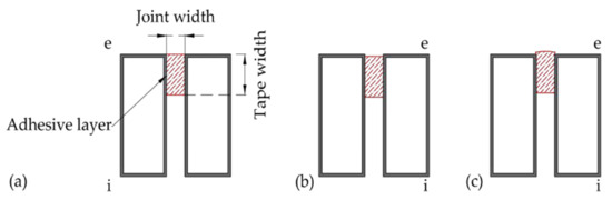
Figure 1.
(a) Width of a foam sealing tape with an adhesive layer on one side and installed in a joint with specified joint width (flush position), (b) recessed position (2 mm) of foam sealing tapes, (c) protruding position (2 mm) of foam sealing tape (e = exterior, i = interior).
In a second series of tests, the watertightness of a single layer of foam sealing tape (S1 and S2) was compared with the watertightness of two layers of foam sealing tape with a cavity in between (D1) and prototypes of foam sealing tapes with integrated drainage cavities (P1 and P2) (Figure 2). The cavity width was varied between 5 mm, 8 mm, and 10 mm to assess the drainage capacity and the feasibility of integrating drainage possibilities in joints sealed by means of a single or double layer of foam sealing tapes.
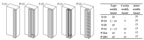
Figure 2.
S (1): single foam sealing tape (20 mm width), D (1): two layers of foam sealing tape (20 mm width) with air cavity of 5 mm, S (2): single foam sealing tape (40 mm width), P (1): prototype 1 with continuous drainage cavity, P (2): prototype 2 with discontinuous drainage cavity.
The first prototype (P (1)) consisted of four separate foam sealing tapes with a width of 15 mm adhered to an EPDM foil (with a width of 40 mm) resulting in a continuous drainage cavity of 10 mm over the length of the tape on both sides of the foil [31].
The second prototype (P (2)) consisted of a foam sealing tape with a width of 40 mm and discontinuous drainage cavities over the length of the tape. The specific geometry of the foam tape was obtained by punching out the cavities.
To obtain good pressure equalization (>90%), the airtightness of the inner seal should be at least ten times higher than the airtightness of the outer seal [26] or in case of joints, Burgess found that a ratio of joint opening area to cavity volume of over 0.05 m−1 will result in a pressure equalization percentage greater than 96% [32]. To this end, a drainage opening with a height of 15 mm and angled towards the exterior was provided at the bottom of the outer seal of sample D1 and openings with a height of 25 mm at both sides of the EPDM foil of prototype P1.
2.3. Test Setup
To the knowledge of the authors, there is no European standard that describes a test procedure to evaluate the watertightness performance of joints between building components or more specifically the performance of pre-compressed foam sealing tapes. Within the European context, however, both the European Assessment Document (EAD) on joints around windows and joints in building facades [33] and the German Standard DIN 18542 [34] describe a methodology to evaluate the performance of foam sealing tapes.
Based on the prescriptions of EAD [33] and DIN 18542:2020 [34] a test setup to evaluate the performance of pre-compressed foam sealing tapes was constructed (Figure 3). The test setup consisted of an air- and watertight plywood box, open to one side, against which the test specimen could be pressurized. In between the box and the specimen, a cellular rubber tape was provided to ensure an air- and watertight seal. In the test setup, a spraying rack with one spray nozzle was provided at a distance of 250 mm from the external face of the specimen as prescribed by EN 1027 [35]. The setup was connected to a test rig by means of a flexible tube. The test rig contained a frequency-controlled fan system capable of generating steady-state air pressure.
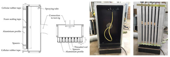
Figure 3.
From left to right: Vertical cross-section of test setup with test specimen; Horizontal cross-section of test setup with test specimen; Test setup with spraying tube; Back view of test specimen.
The test specimens consisted of nine rectangular aluminum profiles held together by means of a threaded rod. Spacers were applied in between the profiles to ensure a uniform joint width over the length of the specimen. Six to eight individual joints with a length of 1 m could be evaluated during one test, depending on the joint width.
2.4. Test Procedure
Both EAD [33] and DIN 18542:2020 [34] prescribe that the resistance of pre-compressed foam sealing tapes to driving rain should be determined according to the European standard EN 1027 [35] (concerning the watertightness of window frames). The test procedure described in EN 1027:2016 [35] is consequently applied in the presented study to evaluate the watertightness performance of the pre-compressed foam sealing tapes.
During the test, water was constantly sprayed at a fixed spray rate of 2 L/min·m2 onto the external face of the test specimen. In the first 15 min of the test, water was sprayed at a test pressure of 0 Pa. Afterwards, the pressure was increased every 5 min in steps of 50 Pa up to 300 Pa and from 300 Pa in steps of 150 Pa. Each water leak that was visible at the interior side of the joints and the corresponding pressure difference were documented.
The tests performed during the first series of tests ended at 600 Pa, as 600 Pa is often applied as a criterion for the watertightness of foam sealing tapes (see Section 2.5). The tests performed to evaluate the performance of drained foam sealing tapes ended at 1050 Pa, as a higher performance than the single foam sealing tapes evaluated in the first series of tests was expected. Each sample presented in Table 2 and Figure 2 was evaluated once. No repetitions were conducted.
All evaluated joints were sealed by means of pre-compressed foam sealing tapes without any additional air barrier on the inside. Hence, the applied pressure difference acted entirely over the evaluated foam sealing tapes either applied as a single barrier or as a combination of two barriers. The foam sealing tapes were also directly exposed to the sprayed water.
2.5. Evaluation Criteria
The European Assessment Document [33] states that the watertightness of joints sealed by means of foam sealing tapes should be classified according to EN 12208 [36]. EN 12208 describes watertightness classes for windows and doors based on the maximum pressure difference (Pmax) at which no water leaks are observed at the interior side of the specimen during a watertightness test (for example, class 9A corresponds with no water infiltration at a pressure difference of 600 Pa). The Belgian standard NBN B 25-002-1:2019 [37] relates these watertightness classes to a terrain category, base wind speed, and building reference height; for example, materials classified as 9A may be applied in buildings near the coast with a base wind speed of up to 26 m/s and a reference height of up to 42 m.
DIN 18542:2020 [34] on the other hand provides a classification system based on the exposure of the foam sealing tapes when installed in the joints. BG1 or MF1 corresponds to direct exposure of the tapes when installed between façade panels. Watertightness of the tapes up to at least 600 Pa is required when tested according to EN 1027 [35]. Whereas BG2 or MF2 corresponds to a concealed installation of the foam sealing tapes and a watertightness of up to at least 300 Pa.
A similar classification system as described in DIN 18542:2020 was applied in the presented study. No visible water leakage at the interior side up to a pressure of 600 Pa is often used as a criterion for the watertightness of sealing materials in Belgium and is thus also applied in the presented study. No water leakage at a pressure of 300 Pa means that the foam sealing tapes may only be applied in buildings near the coast with a base wind speed of up to 26 m/s and a reference height of up to 8 m according to NBN B 25-002-1:2019 [37].
3. Results and Discussion
3.1. The Effect of Material and Installation Parameters on the Watertightness of Pre-Compressed Foam Sealing Tapes
Independent of the characteristics of the evaluated tapes, most water leakages occurred at the interface between the non-adhesive side of the foam sealing tapes and the aluminum profiles. Only 5 out of 67 tested samples or 1 m-joints showed water leakages at the adhesive side. The adhesive, which is actually only applied to hold the tape in place during installation, apparently provides an additional barrier to water infiltration.
Water leaks through the tape itself were not observed during the conducted tests. Olsson [20] however, found that the evaluated foam sealing tapes were completely saturated after the performed test. The author hypothesized that the foam sealing tapes either took up water or that water was pushed into the tapes. Given the hydrophobic nature of the foam sealing tapes (average contact angle of 137°) in the presented study, only the latter is possible. Counteracting the negative capillary pressure, water may be pushed into open cells with a diameter of 0.36 mm when an external pressure of 600 Pa is applied. No information was available on the cell size of the evaluated foam sealing tapes, but it can be assumed that the size was several times smaller, in particular when the foam sealing tapes were compressed within the joints. The smaller the cell size, the higher the necessary pressure to drive water through the cells. Water leakage through the tapes is thus unlikely to occur under the evaluated circumstances.
At the interface between the aluminum profile and the foam sealing tape however, water leakage is more likely to occur due to the reduced hydrophobicity of the aluminum profiles compared to the foam sealing tapes and thus a reduced pressure difference necessary for water to penetrate at the interface.
The results presented in Section 3.1.1, Section 3.1.2, Section 3.1.3, Section 3.1.4, Section 3.1.5 and Section 3.1.6 only include leakages at the interface between the non-adhesive side of the face-sealed foam sealing tape and the aluminum profile.
3.1.1. Impact of Brand and Reproducibility
Water leakages were visible through joints sealed by means of foam sealing tapes A1 and B1 at the same average pressure difference (Figure 4). Tapes of manufacturer A showed water leakages at a wider range of pressure differences than tapes of manufacturer B, but the average performance is the same. This implies that the density of the foam tapes is not a factor affecting the watertightness of the tapes. However, further research on a wider range of densities is necessary to confirm this finding.
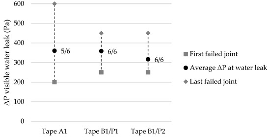
Figure 4.
Applied pressure difference when visible water leaks were observed at the inside of the first and last leaking joints and the average of all tested joints (at the non-adhesive side of the foam sealing tapes) for tapes A1 and B1 and applied by two different people (P1 and P2). The ratio of failed/tested samples (≤600 Pa) is mentioned next to the marker of the average pressure. Both the tape and joint width were 20 mm.
When results were available for tapes with the same characteristics but produced by different manufacturers, the results were averaged and presented together in the following sections.
The foam sealing tapes applied by person 1 showed water leakages at the same range of pressure differences compared to the tapes applied by person 2. The average pressure at water leakage for the tapes applied by person 1 is slightly higher than the pressure for tapes applied by person 2. The difference is, however, insignificant (p = 0.05). The results can thus be reproduced.
3.1.2. Impact of a Varying Tape Width on the Resistance to Driving Rain
The tapes with a width of 20 mm and 40 mm first showed water leaks at a pressure difference of 200 Pa, followed by both the tapes with a width of 50 and 80 mm at a pressure difference of 250 Pa (Figure 5). An increase in the average pressure difference at which water leaks were observed was apparent for foam sealing tapes having a width of 40, 50, and 80 mm. However, on average, the tapes with a width of 80 mm showed water leakages at a pressure difference only slightly higher than tapes with a width of 20 mm, 370 Pa, and 344 Pa, respectively. It was assumed that a wider tape would require a higher pressure difference or a longer time before infiltration occurs as the infiltrated water would need to be transported over a longer depth. However, based on the obtained results, it can be stated that an increase in the tape width does not necessarily result in an increase in watertightness.
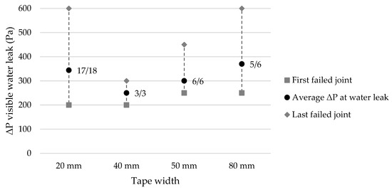
Figure 5.
Applied pressure difference when visible water leaks were observed at the inside of the first and last leaking joints and the average of all tested joints with varying tape width (at the non-adhesive side of the foam sealing tapes). The ratio of failed/tested tapes (≤600 Pa) is mentioned next to the marker of the average pressure. The joint width was 20 mm.
3.1.3. Impact of a Varying Joint Width on the Resistance to Driving Rain
The joint width, on the other hand, did have an impact on the resistance to driving rain (Figure 6). The tested tapes were evaluated at the minimum (10 mm), medium (15 mm), and maximum joint width (20 mm) according to the ranges provided by the manufacturer, resulting in a compression of the tapes of 80%, 70%, and 60%, respectively. A clear difference in performance is apparent for the foam sealing tapes applied to the three evaluated joint widths. Both the pressure difference corresponding to the first water leaks and the average pressure difference increased for a decreasing joint width, and the number of failed joints decreases. The smaller the joint width, the more the foam sealing tape is compressed against the aluminum profiles and thus the higher the pressure difference required to force water through the pathway of interconnected foam cells at the interface. These results are in line with the results obtained by Olsson [20] and Van Linden and Van Den Bossche [21]. Based on these results, it is not surprising that manufacturers pointed out that the application of foam sealing tapes with a specific joint width range to a joint width that is too large is the most common error leading to water leakages. When selecting foam sealing tapes to seal the joints of a building project, it is thus of uttermost importance to choose tapes with the correct joint width range.
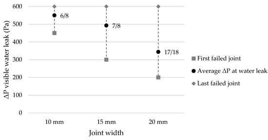
Figure 6.
Applied pressure difference when visible water leaks were observed at the inside of the first and last leaking joints and the average of all tested joints with varying joint width (at the non-adhesive side of the foam sealing tapes). The ratio of failed/tested tapes (≤600 Pa) is mentioned next to the marker of the average pressure. The tape width was 20 mm.
3.1.4. Impact of the Type of Tape on the Resistance to Driving Rain
Foam sealing tapes of type B2 showed water leaks at a higher average pressure difference than foam sealing tapes of type A1 (Figure 7), i.e., 406 Pa and 300 Pa for a width of 54 and 50 mm and 450 Pa and 370 Pa for a width of 84 and 80 mm, respectively. Tape B2 differed from tape A1 by the presence of an airtight coating on the inside of the tape. It is assumed that the airtight coating on the inside of the tapes of type B2 reduces the pressure difference acting over the outer part of the sealant tape, and, as such reduces the driving force for water infiltration at the exterior [26].
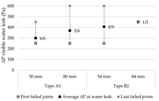
Figure 7.
Applied pressure difference when visible water leaks were observed at the inside of the first and last leaking joints and the average of all tested joints sealed by means of foam sealing tapes of type A1 and B1 (at the non-adhesive side of the foam sealing tapes). The ratio of failed/tested tapes (≤600 Pa) is mentioned next to the marker. The joint width was 20 mm.
3.1.5. Impact of the Position of the Tape Relative to the Outside of the Joint on the Resistance to Driving Rain
The position of the foam sealing tapes relative to the outside of the aluminum profiles had an impact on the resistance of the joints to the sprayed water during the test (Figure 8). When the tapes protruded the aluminum profiles by 2 mm (Figure 1c) a slightly reduced watertightness was measured compared to a flush installation (leakage at an average pressure difference of 300 and 344 Pa, respectively). This result is in line with the observations of Olsson [20]. In contrast, a recessed installation of the tapes (2 mm) resulted in a slightly increased watertightness (Figure 1b) compared to a flush installation (leakage at an average pressure difference of 375 Pa).
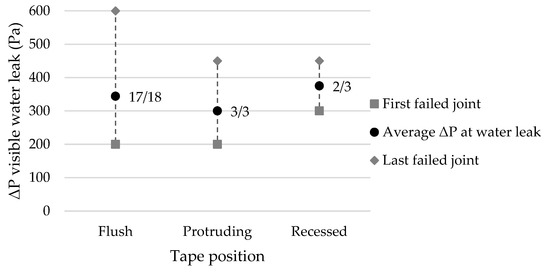
Figure 8.
Applied pressure difference when visible water leaks were observed at the inside of the first and last leaking joints and the average of all tested joints (at the non-adhesive side of the foam sealing tapes) for tapes installed flush with the outside of the aluminum profiles or installed in a protruding or recessed manner. The ratio of failed tapes (≤600 Pa) is mentioned next to the marker. The tape width and joint width were both 20 mm.
The position of the tape relative to the outside of the aluminum profiles affects the exposure of the tape-profile interface and thus the degree of watertightness of the joints, as most water leakages were observed at the interface. When installed flush with the exterior specimen surface, a water film or rivulet may flow over the tape-profile interface. This may cause a pressure addition to the applied pressure and thus the penetration of water towards the interior.
Whereas when foam sealing tapes are installed in a recessed manner, the runoff film or rivulet flow is interrupted and a slightly higher pressure difference is required to force water through the interface.
When the tapes are installed in a protruding manner, the tape-profile interface is covered by the decompressed foam sealing tape. However, the protruding part of the sealing tape will decompress more than the part of the foam sealing tape in the joint as no resistance is given by the profile edges. This results in larger open cells through which water running off the specimen may be pushed due to the applied pressure difference. The water that was pushed in the foam tape may then penetrate further towards the underlying tape-profile interface.
3.1.6. A Single Layer of Pre-Compressed Foam Sealing Tapes Applied to Seal Joints between Building Envelope Components Watertight
Out of 67 evaluated samples, 58 (or 87%) showed water leakages at a pressure difference of 600 Pa or lower, and 30 out of 67 samples (or 45%) failed at a pressure difference of 300 Pa or lower. This implies that only 13% of the tested pre-compressed foam sealing tapes could be applied in an exposed position according to the German standard [34] or could be classified as 9A according to the Belgian standard NBN B 25-002-1:2019 [37]. These results confirm the conclusion of Svensson Tengberg et al. and Olsson [16,20], Farrington et al. [17], and Van Linden and Van Den Bossche [21] that water leakage can be expected through joints sealed by means of a single layer of pre-compressed foam sealing tapes.
The parameters increasing the watertightness of joints sealed by means of a single layer of pre-compressed foam sealing tapes were a reduced joint width, resulting in higher compression of the foam tapes, a recessed position of the foam tape, and the presence of an airtight coating at the inner side of the tape. Lacasse et al. [7] also found that when the plane of airtightness, resulting in the greatest pressure drop, was located on the interior side of a window-wall interface and thus away from the wetted plane, the amount of infiltrating water reduced. It is thus advisable to apply a pre-compressed foam sealing tape either with an airtight coating on the inside or more preferably combined with an airtight sealing at the interior side of the joint and a pressure-equalized cavity in between.
In theory, water was able to penetrate openings with a diameter of at least 0.7 mm at a pressure difference of 300 Pa and openings with a diameter of at least 0.3 mm at a pressure difference of 600 Pa, assuming that the pressure difference acted entirely over the single layer of pre-compressed foam sealing tape with a contact angle of 137°. Openings with these dimensions and larger are not unlikely to be present, for example, due to a scratch or a small irregularity in one of the joint surfaces. In practice, these openings may result in significant amounts of infiltrating water. Lacasse and Miyauchi for example [11], measured an infiltration rate of 0.003 L/min or 0.18 L/h through a crack with a width of 0.5 mm and a length of 2 mm in a joint sealed by means of elastomeric sealant at a pressure difference of 500 Pa and a spray rate of 1.6 L/min·m2. As it can be assumed that several of these openings will be present over the length of the joints, the amount of infiltrating water cannot be overlooked.
When pre-compressed foam sealing tapes are applied as a single layer, there is no additional barrier to keep out infiltrated rainwater. This means that once the water starts to penetrate the present openings or deficiencies, it may flow further inwards reducing the thermal performance of the insulation or causing premature deterioration of the underlying materials. Taking into account the results obtained in this study, the abovementioned dimensions of openings through which water can penetrate and the resulting infiltration rates, it can easily be understood that several researchers have concluded that water infiltration across the exterior barrier of a sealed joint is inevitable and that a secondary barrier and drainage possibilities should be provided, in particular when pre-compressed foam sealing tapes are applied [16,17,18,20,21,38].
3.2. The Effect of Providing Drainage between Two Layers of Foam Tape on the Watertightness and the Potential of Integrating Pressure-Equalized Drainage Cavities in Foam Sealing Tapes
Similar to the conclusion made by Farrington et al. [17], it was observed that in general, foam sealing tapes applied with drainage possibilities showed increased resistance to water leakage during the test compared to the singular foam sealing tapes (Figure 9). Water leaked through the tape-profile interface of a single foam sealing tape with a width of 20 mm (S 1) at an average pressure difference of 344 Pa. Application of an additional layer of foam sealing tape with a width of 20 mm and air space of 5 mm (D 1), resulted in an average increase of the watertightness of 74% relative to the watertightness of the single tape layer (leakage at an average pressure difference of 600 Pa).
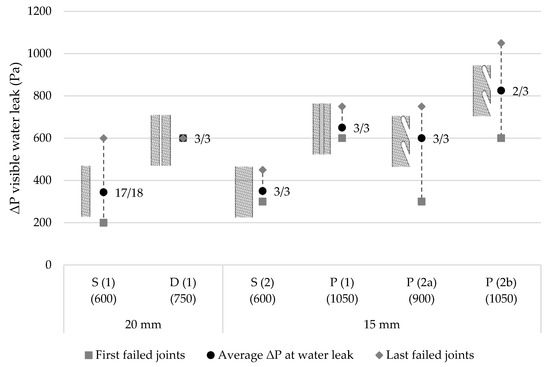
Figure 9.
Applied pressure difference when visible water leaks were observed at the inside of the first and last leaking joints and the average of all tested joints for tapes installed in a face-sealed (FS) and drained (D) manner. The ratio of failed tapes (≤600 (FS) and ≤1050 Pa (D)) is mentioned next to the marker. FS (1) and D (2) were applied to a joint width of 20 mm. FS (3), D (4)–D (5′) were applied to a joint width of 15 mm.
The first water leakages through the double layers of foam sealing tapes were observed through the tape itself at the bottom of the joint. It was assumed that when water infiltrated through the exterior layer of foam sealing tape, it was drained into the air space towards the bottom of the joint. There it drained back to the outside through a drainage opening. However, at a pressure difference of 600 Pa, the amount of infiltrated water through the exterior foam sealing tape presumably increased and due to the pressure difference counteracting drainage, build-up of water at the bottom of the cavity occurred. A similar phenomenon was observed by Lacasse et al. [7] when water penetrated a sealed window-wall interface and accumulated in the sill pan at the bottom of the window.
The build-up of water caused hydrostatic pressure on the interior foam sealing tape. The applied pressure difference in addition to the hydrostatic pressure difference was sufficient to force water through the cells of the foam sealing tape. This implies that the drainage capacity of the cavity and the drainage opening with a height of 15 mm were insufficient to remove the infiltrated water from the cavity at a pressure of 600 Pa.
Water leakages were also observed at the non-adhesive side of the foam sealing tapes, however at higher pressure differences compared to the leakages through the tape itself, i.e., at 750 Pa compared to 600 Pa. These leakages were observed at locations where the width of the air space was locally reduced or even eliminated. It was observed that the foam sealing tapes did not decompress perpendicular to the aluminum profiles, resulting in a reduced cavity width at the non-adhesive side of the foam sealing tapes at some locations. The reduced cavity width resulted in infiltrating water drops crossing the cavity, reaching the interior foam sealing tape, and penetrating the tape-profile interface due to the acting pressure difference. The results suggest that a drainage cavity of 5 mm is sufficiently wide to promote drainage of infiltrated water but not wide enough to accommodate tolerances on the position of the tapes. This observation was taken into account when developing the prototypes with integrated drainage cavities, discussed in the following paragraph.
To evaluate whether the pressure-equalization potential was insufficient, an additional test was performed on two foam sealing tapes with a cavity of 5 mm in between, a drainage opening with a height of 15 mm at the bottom, and an additional opening of 10 mm in the middle of the joints. The addition of this opening in the middle did not result in an increased watertightness. This suggests that a good pressure equalization was already achieved and that the results are in line with the conclusions of Burgess [32]. However, pressure measurements are required to verify this finding.
Both prototypes of foam sealing tapes with incorporated drainage possibilities (P (1) and P (2) in Figure 9) showed an increased watertightness compared to the singular foam sealing tape (S (2) in Figure 9). The singular foam sealing tape showed leakages at an average pressure of 350 Pa, whereas the prototypes with integrated drainage cavities (P (1), P (2a), and P (2b)) showed leakages at an average pressure of 650 Pa, 600 Pa, and 825 Pa, respectively.
Through the foam sealing tapes with continuous drainage cavities P (1), leakages were only observed at the bottom of the joints, through the tape itself. Similar to during the test with the double layer of foam sealing tape D (1), water could not be drained sufficiently through the drainage opening at higher pressure differences, causing water absorption and leakage as a result. When the test was continued after leakage was noticed, it was observed that the leakage location gradually moved upwards, confirming the assumption that water build-up occurred. No water leakages were observed at other locations of the joint, which implies that a cavity of 10 mm is sufficiently wide to accommodate tolerances on the decompression orientation of the foam sealing tapes and to reduce water drops crossing the cavity and reaching the interior barrier.
Similar observations were made for the prototypes with discontinuous drainage cavities P (2) as water leakages were only observed at an average pressure difference of 825 Pa when drainage cavities with a width of 10 mm P (2b) were applied compared to water leakages at an average pressure difference of 600 Pa when drainage cavities with a width of 8 mm were applied P (2a).
Farrington et al. [17] suggested that the width of the drainage channel between the evaluated silicone sealant applied at the exterior and pre-compressed foam tape applied at the interior should be at least ½ inch or 12.7 mm. On the other hand, a minimum cavity width of 10 mm is often prescribed for external walls, for example by the Canadian Building Code [39], as it is assumed that for this width, capillary effects will be diminished and that the largest portion of the infiltrated water will be drained along the inner side of the exterior barrier.
The prototypes with integrated drainage cavities showed promising results to seal joints between building envelope components watertight. However, future research is necessary to assess more in detail the required dimensions of the drainage cavity and drainage openings in terms of the required drainage capacity and pressure equalization to ensure that water penetration towards the interior is prevented.
4. Conclusions
This study investigated the performance of pre-compressed foam sealing tapes to seal vertical joints between different building envelope components watertight. The effect of various material and installation parameters on the watertightness of foam sealing tapes applied as a single barrier was evaluated as well as the effect of including a second layer of foam sealing tape and a drainage cavity in between, and the potential of integrating drainage cavities into a single layer of foam sealing tape.
It was found that the watertightness performance of pre-compressed foam sealing tapes was affected by the joint width or the compression of the tape, the presence of an airtight coating at the inner side of the tape, and the position of the tape relative to the exterior surface of the adjacent panels. The tape width did not affect the watertightness.
Notably, 87% of the foam sealing tapes applied as a single barrier showed water leakages at the interior side of the joints at a pressure difference of 600 Pa or lower. It is therefore recommended to apply drained foam sealing tapes.
Applying a secondary layer of foam sealing tape behind the exterior one and a cavity in between resulted in an increase of the watertightness of 74% compared to a face-sealed foam sealing tape (average pressure of 600 Pa compared to 344 Pa). Integrating drainage possibilities in a single foam tape sealing layer resulted in an increase of the watertightness of more than 136% (average pressure of 825 Pa compared to 350 Pa). The advantage of integrating drainage cavities into a single foam sealing tape is the reduced labor time and detailing complexity compared to two layers of foam sealing tape.
Future work should be conducted to further characterize these foam sealing tapes with integrated drainage. Both laboratory and field tests are recommended to evaluate the resistance to driving rain of horizontal and vertical joints, intersections between horizontal and vertical joints, and joints between various substrates.
Author Contributions
Conceptualization, S.V.L. and N.V.D.B.; methodology, S.V.L.; validation, S.V.L.; formal analysis, S.V.L.; investigation, S.V.L.; writing—original draft preparation, S.V.L.; writing—review and editing, S.V.L. and N.V.D.B.; supervision, N.V.D.B. All authors have read and agreed to the published version of the manuscript.
Funding
This research received no external funding.
Data Availability Statement
Data is contained within the article.
Conflicts of Interest
The authors declare no conflict of interest.
References
- Van Den Bossche, N.; Blommaert, A.; Daniotti, B. The Impact of Demographical, Geographical and Climatological Factors on Building Defects in Belgium. Int. J. Build. Pathol. Adapt. 2022, 25. Available online: https://www.emerald.com/insight/content/doi/10.1108/IJBPA-11-2021-0157/full/html (accessed on 2 January 2023). [CrossRef]
- Van Linden, S.; Van Den Bossche, N. Watertightness performance of face-sealed versus drained window-wall interfaces. Build. Environ. 2021, 196, 107824. [Google Scholar] [CrossRef]
- Maroy, K.; Van Linden, S.; De Vogelaere, K.; Van Den Bossche, N.; Steeman, M. Air- and water tightness of prefabricated envelope modules for the renovation of buildings. In Proceedings of the 14th International Conference on Durability of Building Materials and Components (XIV DBMC), Ghent, Belgium, 29–31 May 2017; p. 12. [Google Scholar]
- Bassett, M.; Overton, G. Measuring the Weathertight Performance of Flashings. Buildings 2015, 5, 130–148. [Google Scholar] [CrossRef]
- Olsson, L. Rain resistance of façades with façade details: A summary of three field and laboratory studies. J. Build. Phys. 2018, 41, 521–532. [Google Scholar] [CrossRef]
- Salzano, C.T.; Masters, F.J.; Katsaros, J.D. Water penetration resistance of residential window installation options for hurricane-prone areas. Build. Environ. 2010, 45, 1373–1388. [Google Scholar] [CrossRef]
- Lacasse, M.A.; Armstrong, M.; Ganapathy, G.; Rousseau, M.; Cornick, S.M.; Bibee, D.; Shuler, D.; Hoffee, A.; Hardman, B.; Carll, C.G.; et al. Assessing the Effectiveness of Wall-Window Interface Details to Manage Rainwater—Selected Results from Window Installation to a Wall Sheathed in Extruded Polystyrene. J. ASTM Int. 2009, 6, 101270. [Google Scholar] [CrossRef]
- Bassett, M.R.; Burgess, J.C.; Camilleri, M.J. The Weathertightness of Window-to-Wall Joints—Dependency on Installation Details. In Proceedings of the IRHACE Annual Conference, Hamilton, ON, Canada, January 2003; p. 11. Available online: https://www.researchgate.net/publication/281348424_The_weathertightness_of_window-to-wall_joints__Dependency_on_installation_details (accessed on 2 January 2023).
- Huff, D.N. Non-destructive testing of elastomeric joint sealants in construction. In Proceedings of the 11th DBMC International Conference on Durability of Building Materials and Components, Istanbul, Turkey, 11–14 May 2008. [Google Scholar]
- Lacasse, M.A.; Miyauchi, H.; Hiemstra, J.; Wolf, A.T.; Dean, S.W. Water Penetration of Cladding Components—Results from Laboratory Tests on Simulated Sealed Vertical and Horizontal Joints of Wall Cladding. J. ASTM Int. 2009, 6, 102048. [Google Scholar] [CrossRef]
- Lacasse, M.; Miyauchi, H. Water penetration of cladding components—An overview of the vulnerability of sealed joints to water penetration. In Proceedings of the 12th Canadian Conference on Building Science and Technology, Montreal, QC, Canada, 6–8 May 2009. [Google Scholar]
- Chew, M.Y.L. Joint sealant for wall cladding. Polym. Test. 2000, 19, 643–651. [Google Scholar] [CrossRef]
- Wolf, A. Improving the service life of sealed cladding joints through a total quality management approach. In Proceedings of the 3rd International RILEM Symposium on Durability of Building and Construction Sealants, Fort Lauderdale, FL, USA, 2–3 February 2000. [Google Scholar]
- Orlowski, K.; Shanaka, K.; Mendis, P. Design and Development of Weatherproof Seals for Prefabricated Construction: A Methodological Approach. Buildings 2018, 8, 117. [Google Scholar] [CrossRef]
- Orlowski, K.; Shanaka, K.; Mendis, P. Manufacturing, Modeling, Implementation and Evaluation of a Weatherproof Seal for Prefabricated Construction. Buildings 2018, 8, 120. [Google Scholar] [CrossRef]
- Tengberg, C.S.; Olsson, L.; Hagentoft, C.-E. Risk Assessment of Joint Sealing Tape in Joints between Precast Concrete Sandwich Panels Resilient to Climate Change. Buildings 2021, 11, 343. [Google Scholar] [CrossRef]
- Farrington, E.S.; Anderson, T.; Grant, L.; Seraderian, R. Precast concrete–to–precast concrete facade joints using precompressed expandable foam. PCI J. 2019, 64, 12. [Google Scholar]
- Gasparri, E.; Aitchison, M. Unitised timber envelopes. A novel approach to the design of prefabricated mass timber envelopes for multi-storey buildings. J. Build. Eng. 2019, 26, 100898. [Google Scholar] [CrossRef]
- Vandemeulebroucke, I.; Kotova, L.; Caluwaerts, S.; Van Den Bossche, N. Degradation of brick masonry walls in Europe and the Mediterranean: Advantages of a response-based analysis to study climate change. Build. Environ. 2023, 230, 109963. [Google Scholar] [CrossRef]
- Olsson, L. Regntäthet Hos Prefabricerade Betongsandwichväggar Med Fönster—Och Balkonganlutningar; RISE: Gothenburg, Sweden, 2021. [Google Scholar]
- Van Linden, S.; Van Den Bossche, N. Comparative study on the feasibility of watertight face-sealed building joints under simulated wind-driven rain conditions. Build. Res. Inf. 2021, 49, 748–762. [Google Scholar] [CrossRef]
- Garden, G.K. Rain Penetration and Control. Natl. Res. Counc. Can. 1963, 40. Available online: https://nrc-publications.canada.ca/eng/view/object/?id=85c77a08-0a5b-4920-8dd5-e8c1ebdf878a (accessed on 2 January 2023).
- Recatalá, M.A.; Morales, S.G.; Van den Bossche, N. Pressure-equalised façade systems: Evaluation of current watertightness test standards used to assess the performance of enclosure components. J. Build. Phys. 2020, 43, 369–397. [Google Scholar] [CrossRef]
- Støver, E.A.; Sundsøy, M.H.; Andenæs, E.; Geving, S.; Kvande, T. Rain Intrusion through Horizontal Joints in Façade Panel Systems—Experimental Investigation. Buildings 2022, 12, 1497. [Google Scholar] [CrossRef]
- Killip, I.R.; Cheetham, D.W. The prevention of rain penetration through external walls and joints by means of pressure equalization. Build. Environ. 1984, 19, 81–91. [Google Scholar] [CrossRef]
- Van Den Bossche, N.; Janssens, A.; Moore, T.; Lacasse, M. Development of numerical model for determination of pressure equalization in facades during wet conditions. Build. Environ. 2020, 178, 106919. [Google Scholar] [CrossRef]
- Straube, D.J. Pressure Moderation and Rain Penetration Control. In Proceedings of the OBEC PER Seminar, University of Waterloo, Waterloo, ON, Canada, February 2001; p. 51. Available online: https://rkeleher.com/documents/Pressure_Equalized_Rainscreen-Straube.pdf (accessed on 2 January 2023).
- Kumar, K.S. Pressure equalization of rainscreen walls: A critical review. Build. Environ. 2000, 35, 161–179. [Google Scholar] [CrossRef]
- Rousseau, M.Z.; Poirier, G.F.; Brown, W.C. Pressure Equalization in Rainscreen Wall Systems; Institute for Research in Construction, National Research Council of Canada: Ottawa, ON, Canada, 1998; p. 17. [Google Scholar]
- Isaksen, T.; Rain Penetration in Joints. Influence of Dimensions and Shape of Joints on Rain Penetration. 1966. Available online: https://sintef.brage.unit.no/sintef-xmlui/handle/11250/2408115 (accessed on 20 February 2023).
- Van Linden, S.; Van Den Bossche, N. Sealing Strip for Sealing Joints between the Surfaces of Two Adjacent Components. WO2022157023A1, July 2022. Available online: https://worldwide.espacenet.com/patent/search/family/074215713/publication/WO2022157023A1?q=WO2022157023A1 (accessed on 2 January 2023).
- Burgess, J.C. Air pressure equalization in rainscreened joints by geometric alteration. Build. Environ. 1995, 30, 13–18. [Google Scholar] [CrossRef]
- Joint Sealing Tape on the Basis of Pre-Compressed Flexible Polyurethane Foam for Sealing around Windows and Joints in Building Facades; European Organization for Technical Assessment: Brussels, Belgium, 2018.
- DIN 18542; Impregnated Sealing Tapes Made of Cellular Plastics for Sealing of Outside Wall Joints—Requirements and Testing. Deutsches Insititut für Normung: Berlin, Germany, 2020; p. 37.
- EN 1027; Windows and Doors—Water Tightness—Test Method. European Committee for Standardization: Brussels, Belgium, 2016.
- EN 12208; Windows and Doors—Watertightness—Classification. European Committee for Standardization (CEN): Brussels, Belgium, 2000.
- NBN B 25-002-1; Buitenschrijnwerk—Deel 1: Voorschrift van Algemene Prestaties—Vensters en Vliesgevels. Bureau voor Normalisatie: Brussels, Belgium, 2019.
- Lstiburek, J.W. Rain Control: Drained, Barrier and Mass. ASHRAE J. 2020, 62, 76–81. [Google Scholar]
- Canadian Commission on Building and Fire Codes. National Building Code of Canada 2020 Volume 1; National Research Council of Canada: Ottawa, ON, Canada, 2020.


Disclaimer/Publisher’s Note: The statements, opinions and data contained in all publications are solely those of the individual author(s) and contributor(s) and not of MDPI and/or the editor(s). MDPI and/or the editor(s) disclaim responsibility for any injury to people or property resulting from any ideas, methods, instructions or products referred to in the content. |
© 2023 by the authors. Licensee MDPI, Basel, Switzerland. This article is an open access article distributed under the terms and conditions of the Creative Commons Attribution (CC BY) license (https://creativecommons.org/licenses/by/4.0/).