1. Introduction
With the aesthetic development of architectural design, the modern architectural curtain wall is more artistic and has a greater decorative sense and has become a landmark of modern cities [
1]. A look at some of the more ornate landmarks at home and abroad shows that their stylish and unique atmosphere has made them a sight to behold in all major cities [
2,
3]. For example, in a natural ecological hotel in Shanghai (the Tianma Mountain World Trade Pit Hotel), an irregular glass facade building in Beijing (the headquarters building of China Central Television) and a carved tower building in the capital of Kuwait (Al Hamm Rata), the exterior maintenance structures all use a smooth curved curtain wall. With the promotion of the idea of green building, the curtain wall building system is being developed toward high performance and improved safety, presenting an overall development trend of sustainability, industrialization, informatization and intelligentization [
4,
5].
After entering the 21st century, due to the continuous development and expansion of the construction market, many curtain wall companies have adopted the strategy of winning bids at low prices in order to compete in the market, thus increasing the winning rate [
6], so it is particularly important for curtain wall companies to control project costs. Additionally, as the exterior of the building, its shape changes can highlight the designer’s preference for architectural aesthetics. Increasing numbers of owners are beginning to attach importance to the novelty and rich color of the curved curtain wall [
7], and the production and processing cost of curved curtain walls is also a problem worth paying attention to for many curtain wall enterprises. It is of great interest to the curtain wall industry to find out how to make a profit while maintaining the aesthetics of the building and at the same time reducing manufacturing costs.
Cost control is one of the research directions that curtain wall companies need to pay attention to in order to achieve long-term development and to pursue the maximum short-term profit of a single project to realize the long-term competitive advantage and maximum value of enterprises. Therefore, strengthening the research on the cost control of building curtain walls is of great significance to improve the competitiveness of enterprises [
6] and can provide a reference for the cost of similar projects [
3]. The material costs of the panel and keel account for 70~80% of the cost of component curtain wall engineering [
8,
9].
Therefore, in view of the design and cost optimization of a single building curtain wall, this paper takes a single keel and single panel as the main research subjects and studies the cost control of a single curtain wall based on the black-box optimization algorithm, which provides a novel direction for the design optimization of curved curtain walls. Driving cost optimization through design optimization, this study provides new ideas for the cost control of single curtain walls. The second section of this paper describes the practical and research status of curtain wall optimization and cost control. Section III describes the external procedures used in this paper for curtain wall design optimization. Section IV describes the specific optimization elements of the comprehensive optimization scheme and the comprehensive set of cuts. Section V takes the actual project as an example to demonstrate the feasibility and advantages of the comprehensive optimization scheme proposed in this paper from multiple perspectives. Finally, a summary of the study and the future research direction are given.
The innovations presented in this paper are as follows:
First, the biggest difference between this optimization method and the traditional building curtain wall skin optimization method is that, considering the characteristics of a single building curtain wall, this paper proposes to take keel optimization as guidance and carry out circular arc fitting based on the theoretical keel track line to directly reduce the material cost by optimizing the keel radius, which provides a new method for the optimization of a single building curtain wall.
Secondly, addressing the problems of the functional relationship between various optimization variables being very fuzzy and the optimization demand in the process of the design optimization of a single building curtain wall being highly complex, this optimization introduces the black-box optimization algorithm in the deepening design stage to provide theoretical support for the optimization scheme.
Thirdly, the last innovation of this paper is putting forward the reverse-cutting method to find the optimal length of the set rule. The use of the fixed-length data combined with the forward-cutting method can further improve the utilization rate of materials, which improves the traditional cutting method and reduces the material cost.
2. Research Background
2.1. Keel Optimization
In the optimization of a bending keel, Tian Hengyin et al. used parametric BIM technology to optimize the bending radius of an aluminum square pass according to the span size, which reduced the die opening cost [
10]. Shi Chunfang et al. made full use of the space of the construction layer to place the single-curved beam and reduce the double curvature of the secondary beam [
11]. Jiang Shuren et al. proposed using a round tube instead of a square tube as the main keel of the hyperbolic curtain wall to reduce the amount of aluminum mold opening [
12]. However, it is difficult and costly to process a keel shaped by bending and twisting, so Ying Jun et al. proposed to replace the original keel with discounted profiles of different lengths by using the parametric merging algorithm according to the different bending and twisting degrees of the original keel [
13].
2.2. Panel Optimization
In terms of panel optimization, Cheng Xiqi et al. used curvature analysis and combined it with annealing simulation algorithms to optimize the hyperbolic panel to a single surface and the single surface to a flat surface [
14]. Yang Xiaolin et al. used zebra stripes to analyze the smoothness of surfaces during the expansion design stage, which corrected and improved the continuity of surfaces and optimized the straightening of trusses and skin support rods, which reduced the cost of curtain wall materials to a certain extent [
15]. On this basis, Huang Man et al. optimized the scheme for the outer skin of the curtain wall; that is, they analyzed and optimized the slope of the opposite side according to the plate size and partition principle of the curtain wall [
16]. Due to the deviation of the main structure itself in the construction process, Chen Hui et al. replaced the hyperbolic panel with non-curved brittle materials, fitted the surface by adjusting the glass fixing base and assembled the aluminum alloy frame in advance in the processing plant. Although the optimization improved the initial scheme, it was difficult to truly reflect the smoothness of the complex skin modeling [
17]. Based on this, Wang Yongping et al. reduced the warpage rate of the panel by redividing the panel grid [
18]. Huang Haozou et al. proposed a compound optimization scheme using a genetic algorithm with multi-objective optimization as the main solution design optimization and single-objective deepening design optimization, which effectively reduced the cost of curved curtain wall projects, but the fit of the panel to the keel after optimization is still to be discussed [
19].
2.3. Design Optimization
Yuxing W. et al. used quantum genetic algorithms to optimize the structural design of office building maintenance structures, including glass curtain walls, and the total cost decreased by 35.3% compared with the original design [
20]. T.K. Lim et al. used an SQCO system that combines a multi-objective genetic algorithm with quality function deployment to determine the optimal tradeoff between the building owner’s and contractor’s satisfaction, using this approach to assist the researchers in quickly determining the best design alternative to minimize construction costs while improving construction quality [
21]. In 2017, Lee A.D. et al. combined a genetic algorithm and parametric control geometric model to find the best approximate shape of the extruded parts of a specific building curtain wall. By using this method, metal content may be reduced by 20% or more [
22]. Lee A.D. et al. numerically optimized over 1000 unique curtain wall systems and optimized each system with different design criteria, using this optimization method to analyze the extent to which different factors affect aluminum content, such as floor height, support location and design wind pressure, ultimately showing that metal cost savings of 40% or more can be achieved by making modest modifications to common layout geometries and specifications [
23]. Bogar et al. proposed a simulation-based multi-objective optimization approach to modularize the facade of the curtain wall to determine the layout with minimal total cost while maximizing the lighting of the room, which considers the building’s environmental performance and investment and operating costs from the design stage [
24]. Rapone et al. proposed using the PSO algorithm coupled with a dynamic energy simulation engine to minimize the total carbon emissions from building operations. They discussed the results of four facade optimizations with different orientation, which highlighted the potential savings compared with standard facade structures [
25]. Chen K. et al. applied the principles of manufacturing and assembly design (DFMA) to curtain wall systems (CWS) and took an actual commercial building as an example to reveal that DFMA-oriented design can not only reduce material cost and waste but also reduce the time required for on-site assembly and improve quality and aesthetic performance [
26]. Yu et al. used a genetic algorithm to propose a new green building design scheme: an envelope design scheme based on environmental data [
27]. Zhang Longwei et al. proposed to optimize the form of a curved curtain wall and photovoltaic module configuration based on sunshine performance analysis and a genetic algorithm, which not only improved the power generation efficiency of a BIPV curved curtain wall but also reduced the cost [
28].
Although the existing optimization method reduces the project cost of curtain wall engineering from many perspectives and has certain application guiding value in the single optimization of the panel and keel, the cost reduction rate of each optimization direction is different, and the existing deepening design process and the impact of a single direction of optimization on the remaining system are not considered. The optimization of the panel and keel in the design stage is a quick way to directly reduce the cost of a curtain wall. Secondly, the existing optimization mainly reduces the bending types of the panel and keel using a single-objective optimization algorithm or replaces the single and double area fitting effect with straight sections. However, the above methods seldom consider the overall degree of fit and smoothness of the keel and panel after optimization and do not consider the optimization of the cutting aspect. Therefore, how to effectively select the appropriate optimization algorithm according to the optimization content and use the algorithm to effectively optimize the panel and keel is the focus of subsequent research.
3. Optimization Platform
Currently, parameterization technology is relatively mature in the field of curtain wall engineering. In this study, Rhino and Grasshopper were selected as software platforms to assist the design and optimization of building curtain walls. This platform integrated performance simulation and a black-box optimization algorithm into a GUI without programming functions [
29].
In this study, mainly using Rhino and Grasshopper platforms as the carrier, and with the help of two extension plug-ins, Opossum and Wallacei, the black-box optimization algorithm was applied in the single keel and panel optimization and set cut optimization.
Opossum encapsulates two optimal single-objective black-box optimization algorithms: RBFOpt and CMA-ES. The plug-in is a model-based optimization tool with a GUI that has three tabs: the first TAB selects maximization and minimization and displays the convergence graph as an animation; the second TAB defines stop conditions and performs and records multiple optimization runs; and the third TAB takes the command line arguments to RBFOpt. Opossum presents users with a complex and innovative optimization library in a familiar and easy-to-learn way [
30].
Wallacei uses NSGA-II as the main algorithm for multi-objective optimization calculation and uses the K-means method as the clustering algorithm. In one interface, it integrates the four functional layouts of algorithm parameter setting, optimization analysis, scheme selection and knowledge forums. Multiple optimization schemes can be derived by setting different analysis parameters. At the same time, the plug-in can be simulated in Grasshopper3D in real time, which is convenient for users to intuitively observe the evolution of the situation.
4. Research Method
In this section, the comprehensive optimization scheme and comprehensive cutting are described in detail. The comprehensive optimization scheme refers to the optimization of the keel radius and the whole panel with the help of single-objective and multi-objective black-box optimization algorithms. Comprehensive cutting is a cutting optimization method that combines reverse cutting and forward cutting.
4.1. Comprehensive Optimization Scheme
4.1.1. Single-Curve Keel Optimization
Most of the existing research on single-keel optimization optimizes part of a single keel into a straight keel through arch height analysis, but this method reduces the cost by relatively little, and the distance between the keel and the panel cannot be quantitatively analyzed, which leads to the existence of a spindle cavity between the panel and the keel, which is not conducive to panel fixation and even leads to a smooth connection between the panel and other plates after installation. In order to further improve the efficiency of keel optimization, the proposed comprehensive optimization scheme mainly combines the black-box optimization algorithm assisted arc fitting to achieve the purpose of keel radius optimization.
The measurement index of this optimization method is keel material cost (A), which mainly includes three parts: measuring cost, total raw material cost and total processing cost. The above variables are all related to the quantity of raw materials (m) and length of raw materials (n) under each fixed size, so the keel cost A is positively related to m and n. Hence, the two key variables need to be obtained in the optimization process.
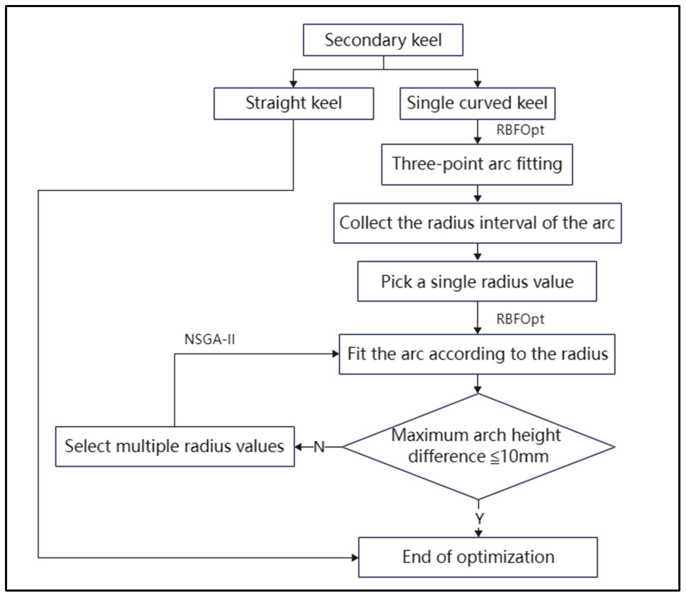
Firstly, the keel arch height was calculated according to the conventional method, and the keel arch height distance was used to classify the keel: the keel whose arch height less than or equal to 10 mm was directly optimized into a straight keel. For a single keel with an arch higher than 10 mm, the arc best fitting the original keel should be found within the error range by using the single- and multi-objective black-box optimization algorithm. Secondly, the radius of the fitting arc should be collected. Keels with the same radius value should be grouped into one category, and finally, the cutting process should be conducted according to the keel radius, which reduces the processing time. Therefore, this approach minimizes the cost of a single keel from two perspectives.
The single-objective black-box optimization algorithm used in single-keel optimization is RBFOpt, and the multi-objective black-box optimization algorithm is NSGA-II. The single-objective optimization is mainly used in two stages: firstly, the arc is fitted according to the track line of the original keel; secondly, the arc is fitted again by selecting a single radius value within the radius interval. When the value of a single radius exceeds the error range, the multi-objective optimization algorithm is used to select multiple radius values for circular arc fitting. According to the relevant regulations of curtain wall engineering technical specifications, the error of a single keel should be controlled within 10 mm during each optimization process [
31,
32]. Therefore, the optimization scheme of each stage in the optimization process of a single keel is as follows:
First of all, when completing the arc fitting according to the original keel track line, the optimization scheme is to seek the best parameter point on the original keel track line and use the parameter point to fit the arc, so that the maximum arch height difference between the fitted arc and the original keel track line meets the error range.
Secondly, a single radius value is selected within the radius interval of all fitted arcs. When using a single radius value to fit the arcs again, the optimization scheme is to find a single radius value to fit the arcs again, so that the maximum arch height difference between the arcs fitted again and the original keel track line meets the error range.
If the maximum arch height difference between the circular arc fitted with a single radius value and the original keel track line does not meet the error requirements, the multi-objective black-box optimization algorithm should be used to select multiple radius values to assist the circular arc fitting. Therefore, the optimization scheme of this operation is to find multiple radius values within the radius interval of all fitted arcs to fit the arcs again, so that the maximum arch height difference between the fitted arcs and the original keel track line meets the error range.
The reason for using the radius value to fit the circular arc again is that the circular arc fitted for the first time has many radius values, and the higher the number of radius values, the higher the number of sizing and the higher the sizing cost. Therefore, under the condition that the maximum arch height difference meets the error requirement, select as few radius values as possible within the radius interval to fit the arc again. This operation not only satisfies the error requirement but also reduces the sizing cost.
The specific single-keel optimization process is shown in
Figure 1, and its main steps are as follows:
First, the primary keel and the secondary keel were distinguished. Then, taking the secondary keel as an example, part of the single keel was optimized as a straight keel by arch height analysis, and the unoptimized single keel was screened out;
The two endpoints of the original keel track line and any point on the line were selected for the first arc fitting, during which the single-objective black-box optimization algorithm RBFOpt was used to assist the selection of the best parameter points;
After fitting, the radius interval of all fitted arcs was collected, and a single radius value was found within the interval, which was used to fit the arcs again. During this period, the single-objective black-box optimization algorithm RBFOpt was used to assist in selecting the best radius value;
If the error range was satisfied, the secondary keel optimization ended; if not, the previous step was repeated, and the multi-objective black-box optimization algorithm, NSGA-II, was used to select multiple radius values to assist arc fitting until the constraint requirements were met;
The main keel optimization was the same and will not be described in detail.
4.1.2. Single-Curve Panel Optimization
The process of optimizing the existing single plate mainly includes the optimization of part of the single plate into a straight plate, or the reconstruction of the panel segmentation by redividing the UV dividing line. Although the above method optimizes the panel to a certain extent, the smoothness of the overall skin cannot be considered at the same time, and the degree of fit between the panel and the keel is not taken into account. Therefore, the proposed comprehensive optimization scheme for single-curved panels mainly consists of regenerating the panels based on the optimized keel data.
The measurement index of this optimization method is the maximum and minimum average normal distance between the panel and the keel, which is compared with the normal distance required in the drawing. Therefore, the degree of fit of the keel and the panel is negatively related to the absolute value of the difference between the two normal distances.
By projecting the optimized keel onto the plane where the single-track panel is located in the theoretical scheme and moving a certain position according to the normal distance between the keel and the panel, its projection contour is optimized according to the principle of curve optimization. The optimized projection contour is the orthographic projection contour of the whole panel, and the curve optimization principle is used to help optimize the projection contour. This method not only ensures the smoothness and fluidity of the entire arc but also ensures the overall fit of the panel with the keel from all angles. The panel optimization process in the comprehensive optimization scheme is shown in
Figure 2, and its main steps are as follows:
Firstly, project the optimized keel to the plane where the theoretical unicurved panel of the scheme is located and, after projection, select the starting and ending points of the projected contour line;
Sort all the starting points, regenerate the internal handicap curve according to the sorted points and offset the curve according to the normal distance between the panel and keel;
Using the principle of curve optimization into an arc to optimize the offset curve, the panel stretched into the optimized contour curve is the optimized single-track panel;
Calculate the maximum and minimum average normal distance between the keel track line and the panel.
4.2. Comprehensive Cutting Scheme
The measurement index of this optimization method is the material utilization rate, in which the cost of keel material is negatively related to the material utilization rate.
4.2.1. Reverse Cutting
Set cutting is another important part of cost control after material optimization. Reverse cutting means that according to the length of each optimized keel track line, and using the principle of patchwork length combined with the multi-objective black-box optimization algorithm NSGA-II to help find the best material length and finally balance the remaining head length and the number of raw materials to ensure that the utilization rate does not exceed 100% of this move by setting the number of iterations, the optimal material length can be found within a certain period of time. Using the fixed-length data combined with the forward-cutting method, the utilization rate of materials can be further improved.
Therefore, the optimization scheme of the reverse cutting stage is to find the appropriate length of raw materials so that the length of the residual head and the number of raw materials after arrangement and combination are minimum. The larger the length of raw materials, the higher the total cost of raw materials. The higher the quantity of raw materials, the higher the total processing cost. The larger the length of the residual head, the lower the material utilization rate.
The NSGA-II multi-objective black-box optimization operator, Wallacei, was selected as the optimization tool. After determining the optimization scheme, the iteration parameters were set according to the actual operation logic, and the optimization process could be observed in real time on the optimization platform. The best optimization solution was selected according to the requirements after optimization. The reverse-cutting optimization process is shown in
Figure 3, and the main steps are as follows:
Arrange and combine the length values of each trajectory line of the keel according to the set raw material length by using the collocation length principle;
Consider the length and number of cutter joints required by actual processing and then add them together to calculate the length of raw materials required for each arrangement and combination;
Calculate the utilization rate, the remaining head length and the number of keel trajectory lines for each permutation combination based on the set raw material length;
According to the logical relationship of the optimization scheme, the multi-objective black-box optimization algorithm NSGA-II was used to balance the length of the remaining head and the number of raw materials while reversely calculating the length of raw materials. After certain iteration results, the optimal solution was selected, and the method to judge the optimal solution was that the higher the utilization rate of materials of each arrangement and combination, the better;
This optimal solution is the data of raw material sizing for forward cutting.
4.2.2. Forward Cutting
Forward cutting involves combining the input processing length according to the optimized profile information and planning the cutting scheme according to the input raw material length under the premise of considering the width of the cutting tool slit. The output result is the profile cutting and discharging scheme with the highest material utilization rate. The optimization scheme of forward cutting is mainly to find the blanking combination with the highest utilization rate according to raw material length, raw material information and cutting joint width, and the higher the utilization rate, the lower the material cost.
Forward-cutting optimization selects wire blanking optimization software based on AutoCAD-MSteel, which can output engineering optimization blanking information according to input blanking and raw material information, such as specifications, raw material length and cutting seam width. This method can calculate complex optimization results in a short time. The specific calculation process is shown in
Figure 4, and its main steps are as follows:
Export the optimized keel specification, length and quantity information according to the radius classification and import this information into MSteel software;
Input the raw material information calculated by reverse cutting and the slit width required by actual processing and then optimize the calculation based on the blanking information;
Finally, export the Excel sheet based on the optimization information, which is prepared for the subsequent cost calculation.
5. Application Analysis
5.1. Project Summary
We take Hefei Binhu International Convention and Exhibition Center Phase II as an example. The project is located at the intersection of Jinxiu Avenue and Guangxi Road, Binhu New District, Hefei City, Anhui Province, with a total construction area of approximately 131,500 square meters. The diameter of the roof arc structure is approximately 144 m, which is more than the length of a standard soccer field, making it the largest-span steel truss convention building in China. The comprehensive facade is a full curtain wall structure, in which the length of the metal curtain wall reaches 170 m and the length of the glass curtain wall reaches 180 m. The construction is complicated, and there are more detailed components. The aerial view is shown in
Figure 5.
This study mainly selects the case of an aluminum curtain wall system for optimization research. The selected optimization object is the side elevation curved aluminum curtain wall in the “one diamond”, as shown in
Figure 6. The overall shape of the model to be optimized is a single surface, with a skin area of 514.3 m
2. The entire panel is divided into 415 single panels, of which the main and secondary keel size is 80 × 140 × 5, and the secondary keel is interrupted at the position of the intersection with the main keel.
5.2. Single-Curve Keel Optimization
5.2.1. Comprehensive Optimization of Two-Span and One-Break Main Keel
Considering the actual processing and keel bearing, the main keel in this case is divided into three cases according to the number of spans. According to the number of intersections between the main keel and the secondary keel, and in accordance with the law of the main keel track line from the top left to the bottom right, the two-span and one-break scheme of the main keel is the scheme of two intersection points and one break as one span.
In the three-point arc fitting, the Opossum component parameters are set, where the optimization type is minimize, the optimization algorithm is RBFOpt, iterations exceed (number of iterations exceeded) is set to 200, and the rest are set to the original settings by default. After the run starts, the running process is displayed on the right side of the component interface, as shown in
Figure 7, where iteration is the current number of iterations and value is the optimal target value under the current number of iterations.
In the use of a single-objective black-box optimization algorithm to select a radius value for fitting the arc, the calculation of the lowest arch height difference is greater than 10 mm, so we continue to use the multi-objective optimization component Wallacei for fit optimization. In the Grasshopper interface, the parameters are set as shown in
Figure 8, where Generation Size (iteration size) is 20, Generation Count (number of iterations under each iteration size) is 100, total Population Size (number of iterations) is 2000, crossover probability is 0.9, and the rest are kept at the default settings. The optimization results of the two-span one-break main curved keel are shown in
Table 1.
After optimizing the main keel, a comprehensive cutting process is required. The first step is to perform reverse cutting, where the length of the processed material at the same radius is calculated according to the keel radius classification. In this case, the Wallacei component parameters are set as above, while the best solution is to find a suitable length of raw materials so as to minimize the length of the remaining head and the quantity of raw materials after arrangement and combination. The data on the length of the raw material of the two-span, one-break main bent keel are shown in
Table 2 below. The raw material data are used for forward cutting. Taking the keel numbered 2-Z01 as an example, the statistical table of the blanking combination is shown in
Table 3. The average utilization rate is as high as 97.15%.
5.2.2. Comprehensive Optimization of Three-Span and One-Break Main Keel
According to the number of intersections between the main keel and the secondary keel, and in accordance with the law of the main keel track line from the top left to the bottom right, the main keel has three spans and one break in accordance with the scheme of one break for every three intersections. The optimization results of the three-span one-break main curved keel are shown in
Table 4.
The raw material length data of three spans and one section of the main curved keel are obtained by the reverse cutting of the above main curved keel, as shown in
Table 5. The raw material data are used for forward cutting. Taking keel No. 3-Z01 as an example, the statistical table of its cutting combination is shown in
Table 6. The average utilization rate is as high as 97.05%.
5.2.3. Comprehensive Optimization of Four-Span and One-Break Main Keel
According to the number of intersections between the main keel and the secondary keel, and in accordance with the law of the main keel track line from the top left to the bottom right, the main keel has four spans and one break in accordance with the scheme of one break for every four intersections. The optimization results of the four-span one-break main curved keel are shown in
Table 7.
The raw material length data of four spans and one section of the main curved keel are obtained by the reverse cutting of the above main curved keel, as shown in
Table 8. The raw material data are used for forward cutting. Taking keel No. 4-Z01 as an example, the statistical table of its cutting combination is shown in
Table 9. The average utilization rate is as high as 88.61%.
5.2.4. Comprehensive Optimization of Secondary Keel
The secondary keel is interrupted at the intersection with the main keel, and arch height analysis is used to distinguish the straight keel and single keel. For a single keel, a three-point fitting arc operation is first performed, and then the selected radius is used to fit the arc again, where the single-target black-box optimization algorithm RBFOpt is first selected to pick the radius value for fitting optimization. The optimization results are given in
Table 10 and show that the maximum arch height difference meets the constraint requirements. Therefore, it is no longer necessary to use the multi-objective black-box optimization algorithm to assist in selecting multiple radius values.
Reverse cutting is carried out on the above secondary curved keel, and the raw material length data of the secondary curved keel are shown in
Table 11. The raw material data are used to carry out forward blanking. Taking keel No. C-Z01 as an example, the statistical table of the blanking combination is shown in
Table 12, and the average utilization rate is as high as 96.39%.
5.3. Single-Curve Panel Optimization
The maximum and minimum mean normal distance between the optimized panel and keel are calculated, and the specific data are shown in
Table 13.
5.4. Optimization Benefit Analysis
5.4.1. Quantitative Analysis of Keel Size
The keel sizes of the three schemes are comprehensively compared. The theoretical scheme is the scheme model created according to the relevant layout drawings of the curtain wall keel panel. The deepening scheme is the existing optimization scheme; that is, all of the secondary keels are optimized into straight keels. The main keel for arch height analysis if the arch height value is less than 10 mm keel is optimized into a straight keel, whereas a keel greater than 10 mm is not optimized. The quantity of keel size is related to the material type. By comparing the keel size of the three schemes, the material type required by the three schemes can be theoretically compared. The higher the keel size, the more the material types, and the higher the material cost. The total size of the three schemes is shown in
Table 14.
From the point of view of sizing, the sizing in the theoretical scheme is the highest, up to 53, and that of the deepening scheme is second. The sizing of the three schemes in the comprehensive scheme is lower, but that of the two-span and one-break scheme is the lowest, being as low as 4. Therefore, from the perspective of theoretical analysis, the two-span one-section scheme saves the most cost.
5.4.2. Keel Cost Analysis
According to the market situation of keel pricing, the material cost of the three schemes is calculated after comprehensive consideration of the size price, the total cost of raw materials and the bending cost. The details are as follows: the price of a single fixed length is 300 CNY/ton, the steel wire density of the 140 × 80 × 5 specifications of hot-dip galvanized rectangular steel is 15.98 kg/m, the price of each ton of raw material is 7600 CNY, and the tax price of profile bending is 15 CNY/m.
The mathematical relationship can be expressed as follows:
where the sizing cost is B, the total raw material cost is C, the total processing cost is D, the price of a single sizing is p, the weight of a single raw material is q, the processing cost of a single raw material is r, and the total weight of raw material is s.
The comparative data of the total cost of materials in each scheme are shown in
Table 15.
In the comparative analysis of keel material cost, compared with the theoretical scheme, the comprehensive optimization scheme proposed in this paper can reduce the material cost by 7.83%, 9.92% and 10.92%, respectively, and improve the optimization rate by approximately 9.56% on average. The two-span one-break optimization scheme has the highest optimization rate of 10.92%, and the four-span one-section scheme has the lowest optimization rate among the comprehensive schemes, although it is 0.505% higher than that of the deepening scheme.
5.4.3. Optimization Analysis of Keel Set Cutting
The utilization rate of material under the forward-cutting method is calculated by using the conventional cutting size and compared with the comprehensive cutting method proposed in this paper. The commonly used cutting sizes are 4500, 6000, 7500 and 9000. One keel size is selected from the secondary keel and the main keel of the three schemes, respectively, and the material utilization rate is calculated when the raw material length is four commonly used set sizes. The results are shown in
Table 16.
Combined with the data in the table, for the two-span one-section scheme, taking No. 2-Z01 as an example, the maximum utilization rate of the set optimization method proposed in this paper is approximately 9% higher than that of the above scheme.
For the three-span one-section scheme, taking No. 3-Z01 as an example, the optimization method proposed in this paper is approximately 16% higher than the maximum utilization rate of the scheme mentioned above.
For the four-span one-section scheme, taking No. 4-Z01 as an example, the maximum keel length under the diameter of 4-Z01 exceeds 4500 mm; hence, the common set size of 4500 is not considered. The optimization method proposed in this paper is approximately 11% higher than the above scheme.
For the secondary keel, taking number C-Z01 as an example, the maximum utilization rate of the cutting optimization method proposed in this paper is approximately 6% higher than that of the above scheme.
In summary, by calculating the utilization rate of the four common cutting size schemes under the four keel diameters, compared with the utilization rate calculated by the comprehensive cutting method, the results show that the comprehensive cutting method proposed in this paper can improve the material utilization compared with the traditional forward-cutting method.
5.4.4. Panel Optimization Analysis
As the theoretical scheme panel is modeled according to the drawings, the normal distance between the keel and the panel is 30 mm in the optimal state. Therefore, when comparing the panels, only the keel-optimized schemes, namely the deepening scheme and comprehensive optimization scheme, are considered. The maximum and minimum mean normal distance between the panel and keel of the deepening scheme is shown in
Table 17.
In the comparison of the overall scheme, the maximum and minimum average normal distance between the keel and panel of the comprehensive scheme is smaller than that between the keel and panel of the deepening scheme and is closer to the ideal distance of 30 mm. Therefore, the comprehensive scheme panel is more advantageous in the overall analysis of the two schemes.
Finally, the distance between the comprehensive panel and the deepening panel is compared, where the maximum distance between the two-span one-break scheme panel and the deepening panel is around 6 mm, the maximum distance between the four-span one-break scheme panel and the deepening panel is also around 6 mm, and the maximum distance between the three-span one-break scheme panel and the deepening panel is around 13 mm, but all three distances are very small, indicating that the comprehensive scheme panel is very close to the deepening scheme panel, and the panel is smooth.
6. Conclusions
In this paper, a comprehensive optimization scheme and a comprehensive cutting scheme are proposed for the deepening design stage of a single building curtain wall. Taking the Hefei Binhu International Convention and Exhibition Center Phase II project as an example, the feasibility of the proposed scheme for the optimization of a single curtain wall system is discussed. During the study, the following conclusions were mainly drawn:
First of all, this paper abandons the traditional optimization of the curtain wall panel as the main optimization objective, instead choosing the keel as the key optimization objective to reduce the cost of a single building curtain wall, and puts forward the theory of optimizing the keel radius to reduce the keel size so as to further reduce the cost. From the case study, it can be seen that the material cost is reduced by 9.56% on average.
Secondly, this paper successfully introduced the black-box optimization algorithm into the design optimization of a single building curtain wall, which avoids solving the complex mapping relationship between optimization schemes and then realizes the comparison and selection of optimization schemes in the form of data iteration.
Finally, for the traditional scheme, the reverse sizing method proposed in this paper provides scientific sizing data for forward sizing. The determination of the sizing data changes the traditional conventional sizing. The utilization rate of materials can be greatly improved and the cost of materials can be reduced by using the sizing data for forward sizing.
In the future, we will focus on using big data technology to capture case data and analyze the mapping relationship between variables and analyze the best curtain wall optimization scheme under different settings by combining machine learning, neural network and other information processing methods so as to provide more ideas and methods for the field of curtain wall optimization in the future.
Author Contributions
Conceptualization, L.L. and L.W.; methodology, L.W.; software, L.W., Z.G. and Z.L.; validation, L.L. and L.W.; formal analysis, L.L. and L.W.; investigation, L.W.; resources, Z.G. and Z.L.; data curation, L.L.; writing—original draft preparation, L.L. and L.W.; writing—review and editing, L.L. and L.W.; visualization, L.W.; supervision, L.L., Z.G. and Z.L.; project administration, L.L. All authors have read and agreed to the published version of the manuscript.
Funding
This research received no external funding.
Institutional Review Board Statement
Not applicable.
Informed Consent Statement
Not applicable.
Data Availability Statement
Data are available from the corresponding author and can be shared upon reasonable request.
Conflicts of Interest
The authors declare no conflict of interest.
References
- Zhang, S.; Cheng, H. Analysis on the Characteristics and Development Trend of construction curtain wall Industry in our country. Henan Build. Mater. 2013, 3, 159–160. [Google Scholar] [CrossRef]
- Zhang, Z. Research on Bidding Strategy of Curtain Wall Project; Shandong University: Jinan, China, 2016. [Google Scholar]
- Li, D. Research on Influencing Factors of Unit Curtain Wall Project Cost; South China University of Technology: Guangzhou, China, 2012. [Google Scholar]
- Yang, L. Discussion on the Characteristics and Development of Building Curtain Wall Industry. China New Technol. New Prod. 2019, 22, 141–142. [Google Scholar]
- Yang, S. Green Road of Building Curtain Wall in China. In Proceedings of the China Steel Structure Industry Summit Forum, Guangzhou, China, 24 March 2010; pp. 28–34. [Google Scholar]
- Qi, Y. Research on Cost Control of YE Curtain Wall Project; Harbin Engineering University: Harbin, China, 2013. [Google Scholar]
- Lin, X. Application of BIM Technology in Building Curtain Wall Design. Jiangxi Build. Mater. 2021, 3, 59–60. [Google Scholar]
- Xu, S. Research on Contracting Cost Management of International Project Curtain Wall; South China University of Technology: Guangzhou, China, 2018. [Google Scholar]
- Yi, Z.; Hao, H.; Xu, X.; Xin, W. Design Optimization of Curved Curtain Wall Based on SPEA II-GA-BPNN Algorithm. Adv. Civ. Eng. 2022, 2022, 2548647. [Google Scholar]
- Tian, H.; Zhuo, C.; Guo, Y.; Huang, Z. Application of Parametric BIM technology in hyperbolic curtain wall. Fujian Constr. Sci. Technol. 2018, 4, 77–78. [Google Scholar]
- Shi, C.; Xiong, B.; Zhang, H.; Huang, Y.; Li, Y. Discussion on Deepening Design of Hyperbolic Metal Roofing. Proc. Ind. Archit. Acad. Exch. Conf. 2020, 2, 192–195+175. [Google Scholar]
- Jiang, S.; Dong, X.; Wang, C.; Cheng, H. Construction Technology of hyperboloid Curtain wall and Metal Roof of high-speed railway station in Coastal Area. Constr. Sci. Technol. 2020, 5, 36–43. [Google Scholar]
- Ying, J. Flexible BIM technology application helps complex special-shaped projects become simple—BIM solution for Curtain wall Project of National Network Security Talent and Innovation Base Exhibition Center Hyperbolic glass daylighting roof. Archit. Ski. 2020, S2, 78–80. [Google Scholar]
- Cheng, X.; Li, B.; Chen, B.; Qiu, J.; Xu, Z. Application of BIM technology in Curtain wall project of Xiangyang East Railway Station. Inf. Technol. Civ. Archit. Eng. 2020, 12, 12–19. [Google Scholar]
- Yang, X.; Gong, K. Research on Application of Parametric Design in Curtain wall Design. J. Jilin Jianzhu Univ. 2020, 37, 33–42. [Google Scholar]
- Huang, M.; Qian, H.; Hu, H. Collaborative application of BIM and parametric technology in the optimization stage of special-shaped building design. New Archit. 2022, 5, 67–71. [Google Scholar]
- Chen, H.; Bai, L.; Su, H.; Zhang, Y. Design and Construction of hyperboloid Modeling Structure using noncurved brittle Materials. Build. Constr. 2019, 41, 427–429. [Google Scholar]
- Wang, Y.; Jiang, H.; Jiang, J.; Zhang, Q.; Cai, J. Deepening design method of hyperbolic Titanium-zinc plate roof. Constr. Technol. 2020, 49, 51–54+69. [Google Scholar]
- Zou, Y.; Huang, H.; Xia, X.; Wang, X. Design optimization of curved curtain wall based on Genetic algorithm under cost orientation. J. Zhejiang Univ. Eng. Sci. 2022, 56, 2049–2056. [Google Scholar]
- Wang, Y.; Wei, C. Design optimization of office building envelope based on quantum genetic algorithm for energy conservation. J. Build. Eng. 2021, 35, 102048. [Google Scholar] [CrossRef]
- Lim, T.K.; Jang, W.S.; Choi, J.H.; Lee, D.E. Stochastic quality-cost optimization system hybridizing multi-objective genetic algorithm and quality function deployment. J. Civ. Eng. Manag. 2015, 21, 407–422. [Google Scholar] [CrossRef] [Green Version]
- Lee, A.D.; Shepherd, P.; Evernden, M.C.; Metcalfe, D. Optimizing the Cross-sectional Shapes of Extruded Aluminium Structural Members for Unitized Curtain Wall Facades. Structures 2017, 10, 147–156. [Google Scholar] [CrossRef] [Green Version]
- Adla, B.; Ps, A.; Mce, A. Optimizing the architectural layouts and technical specifications of curtain walls to minimize use of aluminium. Structures 2018, 13, 8–25. [Google Scholar]
- Bogar, D. GA-Optimisation of a curtain wall facade for different orientations and climates. In Proceedings of the BSA2013—1st IBPSA Italy Conference, Bozen, Italy, 30 January 2013. [Google Scholar]
- Rapone, G.; Saro, O. Optimisation of curtain wall faades for office buildings by means of PSO algorithm. Energy Build. 2012, 45, 189–196. [Google Scholar] [CrossRef]
- Chen, K.; Lu, W. Design for Manufacture and Assembly Oriented Design Approach to a Curtain Wall System: A Case Study of a Commercial Building in Wuhan, China. Sustainability 2018, 10, 2211. [Google Scholar] [CrossRef] [Green Version]
- Yu, J.; Lee, M. Optimized Building Envelope by Using based Algorithm and Application to Building Design. J. Chesap. Inst. Spat. Des. 2019, 14, 59–73. [Google Scholar]
- Zhang, L.; Sui, J.; Lv, X.; Guo, C. Research on Design of BIPV Curved Curtain Wall Based on Sunlight Performance Analysis and Genetic Algorithm. Archit. J. 2019, S2, 58–62. [Google Scholar]
- Wortmann, T.; Nannicini, G. Introduction to Architectural Design Optimization. City Netw. Collab. Plan. Health Sustain. 2017, 12, 259–278. [Google Scholar] [CrossRef]
- Wortmann, T. Opossum: Introducing and Evaluating a Model-Based Optimization Tool for Grasshopper; CAADRIA: Hong Kong, China, 2017. [Google Scholar]
- GB 50210-2018; Quality Acceptance Standard GB 50210-2018 for Architectural Decoration Engineering. Ministry of Housing and Urban-Rural Development of the People’s Republic of China: Beijing, China, 2018.
- JGJ/T 324-2014; Standard for Testing Method of Building Curtain Wall Engineering. Ministry of Housing and Urban-Rural Development of the People’s Republic of China: Beijing, China, 2014.
Figure 1.
Keel optimization process in the comprehensive optimization scheme.
Figure 1.
Keel optimization process in the comprehensive optimization scheme.
Figure 2.
Panel optimization process in the comprehensive optimization scheme.
Figure 2.
Panel optimization process in the comprehensive optimization scheme.
Figure 3.
Reverse-cutting optimization process.
Figure 3.
Reverse-cutting optimization process.
Figure 4.
Forward-cutting optimization process.
Figure 4.
Forward-cutting optimization process.
Figure 6.
Exhibition Center Phase II optimization model.
Figure 6.
Exhibition Center Phase II optimization model.
Figure 7.
Schematic diagram of the running process of the component.
Figure 7.
Schematic diagram of the running process of the component.
Figure 8.
Wallacei component parameter setting diagram.
Figure 8.
Wallacei component parameter setting diagram.
Table 1.
Optimization results of the two-span and one-break main curved keel.
Table 1.
Optimization results of the two-span and one-break main curved keel.
| Radius Start Point | Radius Step Length | Maximum Arch Height Difference | Radius Type | Radius Value |
|---|
| 14,500 | 4000 | 6.285 | 2 | 14,500; 18,500 |
Table 2.
Raw material length of the two-span and one-break main curved keel.
Table 2.
Raw material length of the two-span and one-break main curved keel.
| Keel Number | Raw Material Length | Raw Material Quantity | Quantity of Measuring Scale |
|---|
| 2-Z01 | 10,889 | 4 | 2 |
| 2-Z02 | 4849 | 38 |
Table 3.
2-Z01 keel blanking combination.
Table 3.
2-Z01 keel blanking combination.
| Serial Number | Specification | Raw Material Length | Quantity | Utilization Rate | Blanking Combination | Length of
Remaining Head |
|---|
| 1 | 2-Z01 | 10,889 | 1 | 99.90% | 2854 × 1 + 2754 × 1 + 2696 × 1 + 2570 × 1 | 0 |
| 2 | 2-Z01 | 10,889 | 1 | 95.80% | 2711 × 1 + 2576 × 1 + 2573 × 1 + 2571 × 1 | 438 |
| 3 | 2-Z01 | 10,889 | 1 | 98.70% | 2569 × 1 + 2568 × 1 + 2567 × 1 + 1699 × 1 + 1345 × 1 | 116 |
| 4 | 2-Z01 | 10,889 | 1 | 94.20% | 2566 × 1 + 2565 × 3 | 608 |
Table 4.
Optimization results of the three-span and one-break main curved keel.
Table 4.
Optimization results of the three-span and one-break main curved keel.
| Radius Start Point | Radius Step Length | Maximum Arch Height Difference | Radius Type | Radius Value |
|---|
| 14,000 | 3248 | 7.516 | 8 | 17,248; 20,496; 14,000; 147,168; 101,696; 46,480; 143,920; 26,992 |
Table 5.
Raw material length of the three-span and one-break main curved keel.
Table 5.
Raw material length of the three-span and one-break main curved keel.
| Keel Number | Raw Material Length | Raw Material Quantity | Quantity of Measuring Scale |
|---|
| 3-Z01 | 11,300 | 6 | 8 |
| 3-Z02 | 10,733 | 14 |
| 3-Z03 | 7172 | 1 |
| 3-Z04 | 7749 | 17 |
| 3-Z05 | 7922 | 5 |
| 3-Z06 | 3297 | 1 |
| 3-Z07 | 3948 | 1 |
| 3-Z08 | 1978 | 1 |
Table 6.
3-Z01 keel blanking combination.
Table 6.
3-Z01 keel blanking combination.
| Serial Number | Specification | Raw Material Length | Quantity | Utilization Rate | Blanking Combination | Length of
Remaining Head |
|---|
| 1 | 3-Z01 | 11,300 | 1 | 99.60% | 3979 × 1 + 3695 × 1 + 3584 × 1 | 27 |
| 2 | 3-Z01 | 11,300 | 1 | 93.90% | 3907 × 1 + 3849 × 1 + 2853 × 1 | 676 |
| 3 | 3-Z01 | 11,300 | 1 | 99.90% | 3775 × 1 + 3760 × 1 + 3755 × 1 | 0 |
| 4 | 3-Z01 | 11,300 | 1 | 99.90% | 3765 × 1 + 3763 × 1 + 3762 × 1 | 0 |
| 5 | 3-Z01 | 11,300 | 1 | 99.80% | 3761 × 1 + 3759 × 1 + 3758 × 1 | 7 |
| 6 | 3-Z01 | 11,300 | 1 | 89.20% | 3757 × 1 + 3756 × 1 + 1318 × 1 + 1250 × 1 | 1199 |
Table 7.
Optimization results of the four-span and one-break main curved keel.
Table 7.
Optimization results of the four-span and one-break main curved keel.
| Radius Start Point | Radius Step Length | Maximum Arch Height Difference | Radius Type | Radius Value |
|---|
| 14,350 | 3248 | 8.58 | 7 | 16,858; 21,874; 14,350; 137,242; 44,446; 114,670; 19,366 |
Table 8.
Raw material length of the four-span and one-break main curved keel.
Table 8.
Raw material length of the four-span and one-break main curved keel.
| Keel Number | Raw Material Length | Raw Material Quantity | Quantity of Measuring Scale |
|---|
| 4-Z01 | 11,259 | 7 | 7 |
| 4-Z02 | 13,627 | 8 |
| 4-Z03 | 8509 | 1 |
| 4-Z04 | 5171 | 33 |
| 4-Z05 | 6593 | 5 |
| 4-Z06 | 5272 | 1 |
| 4-Z07 | 12,970 | 3 |
Table 9.
4-Z01 keel blanking combination.
Table 9.
4-Z01 keel blanking combination.
| Serial Number | Specification | Raw Material Length | Quantity | Utilization Rate | Blanking Combination | Length of
Remaining Head |
|---|
| 1 | 4-Z01 | 11,259 | 1 | 90.00% | 5208 × 1 + 4925 × 1 | 1116 |
| 2 | 4-Z01 | 11,259 | 1 | 87.50% | 4924 × 1 + 4923 × 1 | 1402 |
| 3 | 4-Z01 | 11,259 | 1 | 87.40% | 4922 × 1 + 4921 × 1 | 1406 |
| 4 | 4-Z01 | 11,259 | 1 | 87.40% | 4920 × 1 + 4919 × 1 | 1410 |
| 5 | 4-Z01 | 11,259 | 1 | 87.30% | 4917 × 2 | 1415 |
| 6 | 4-Z01 | 11,259 | 1 | 87.10% | 4916 × 1 + 4886×1 | 1447 |
| 7 | 4-Z01 | 11,259 | 1 | 93.60% | 3908 × 1 + 3775 × 1 + 2853 × 1 | 708 |
Table 10.
Optimization results of the secondary keel.
Table 10.
Optimization results of the secondary keel.
| Maximum Arch Height Difference | Radius Type | Radius Value |
|---|
| 1.59 | 1 | 15,111 |
Table 11.
Raw material length of the secondary curved keel.
Table 11.
Raw material length of the secondary curved keel.
| Keel Number | Raw Material Length | Raw Material Quantity | Quantity of Measuring Scale |
|---|
| C-Z01 | 6060 | 7 | 1 |
Table 12.
C-Z01 keel blanking combination.
Table 12.
C-Z01 keel blanking combination.
| Serial Number | Specification | Raw Material Length | Quantity | Utilization Rate | Blanking Combination | Length of Remaining Head |
|---|
| 1 | C-Z01 | 6060 | 1 | 96.40% | 1619 × 1 + 1455 × 1 + 1433 × 1 + 1334 × 1 | 199 |
| 2 | C-Z01 | 6060 | 1 | 99.70% | 1328 × 1 + 1252 × 1 + 1185 × 1 + 1153 × 1 + 1122 × 1 | 0 |
| 3 | C-Z01 | 6060 | 1 | 99.70% | 1301 × 1 + 1243 × 1 + 1184 × 1 + 1157 × 1 + 1155 × 1 | 0 |
| 4 | C-Z01 | 6060 | 1 | 99.70% | 1235 × 2 + 1233 × 1 + 1185 × 1 + 1152 × 1 | 0 |
| 5 | C-Z01 | 6060 | 1 | 99.70% | 1232 × 1 + 1230 × 1 + 1227 × 1 + 1201 × 1 + 1150 × 1 | 0 |
| 6 | C-Z01 | 6060 | 1 | 99.70% | 1226 × 1 + 1224 × 1 + 1218 × 1 + 1215 × 1 + 1157 × 1 | 0 |
| 7 | C-Z01 | 6060 | 1 | 79.8% | 1221 × 1 + 1211 × 1 + 1206 × 1 + 1195 × 1 | 1207 |
Table 13.
Distance between the panel and keel of the comprehensive scheme.
Table 13.
Distance between the panel and keel of the comprehensive scheme.
| Comprehensive Scheme Panel | Two-Span One-Break Keel | Three-Span One-Break Keel | Four-Span One-Break Keel |
|---|
| Max | Min | Max | Min | Max | Min |
|---|
| Main Keel | 32.472 | 31.644 | 30.667 | 30.056 | 30.501 | 30.09 |
Main and
Secondary Keel | 31.579 | 30.561 | 32.919 | 31.654 | 30.292 | 29.4 |
Table 14.
Sizing quantity table of three schemes.
Table 14.
Sizing quantity table of three schemes.
| Scheme | Sizing Number of Curved Keel | Sizing Number of Straight Keel | Total |
|---|
| Theoretical scheme | 53 | 0 | 53 |
| Deepening scheme | 40 | 1 | 41 |
| Comprehensive program—two spans and one break | 3 | 1 | 4 |
| Comprehensive program—three spans and one break | 9 | 1 | 10 |
| Comprehensive program—four spans and one break | 8 | 1 | 9 |
Table 15.
The total keel cost for the three schemes.
Table 15.
The total keel cost for the three schemes.
| Scheme | Straight Keel Cost | Curved Keel Cost | Total Cost | Optimization Rate
(Compared to Theoretical Scheme) |
|---|
| Theoretical scheme | 0.0000 | 128,136.7198 | 128,136.7198 | 0.0000 |
| Deepening scheme | 54,157.8180 | 64,540.5319 | 118,698.3499 | 0.0737 |
| Comprehensive program—two spans and one break | 75,980.0101 | 38,168.9556 | 114,148.9657 | 0.1092 |
| Comprehensive program—three spans and one break | 52,112.6976 | 63,307.4892 | 115,420.1868 | 0.0992 |
| Comprehensive program—four spans and one break | 49,378.0404 | 68,721.0126 | 118,099.0560 | 0.0783 |
Table 16.
Material utilization rate under four common sizes.
Table 16.
Material utilization rate under four common sizes.
| Number | Four Common Sizes | Comprehensive Cutting Size |
|---|
| 4500 | 6000 | 7500 | 9000 |
|---|
| 2-Z01 | 62.7% | 88.2% | 70.5% | 78.4% | 97.1% |
| 3-Z01 | 81.2% | 64.5% | 62.7% | 81.2% | 97.1% |
| 4-Z01 | - | 77.6% | 66.5% | 64.7% | 88.6% |
| C-Z01 | 80.1% | 82.6% | 88.1% | 88.1% | 94.6% |
Table 17.
Distance between the deepening scheme panel and the comprehensive scheme keel.
Table 17.
Distance between the deepening scheme panel and the comprehensive scheme keel.
| Deepening Scheme Panel | Two-Span One-Break Keel | Three-Span One-Break Keel | Four-Span One-Break Keel |
|---|
| Max | Min | Max | Min | Max | Min |
|---|
| Main Keel | 32.119 | 30.74 | 30.163 | 29.647 | 30.017 | 29.461 |
Main and
Secondary Keel | 32.329 | 30.809 | 31.8 | 30.67 | 31.908 | 30.729 |
| Disclaimer/Publisher’s Note: The statements, opinions and data contained in all publications are solely those of the individual author(s) and contributor(s) and not of MDPI and/or the editor(s). MDPI and/or the editor(s) disclaim responsibility for any injury to people or property resulting from any ideas, methods, instructions or products referred to in the content. |
© 2023 by the authors. Licensee MDPI, Basel, Switzerland. This article is an open access article distributed under the terms and conditions of the Creative Commons Attribution (CC BY) license (https://creativecommons.org/licenses/by/4.0/).


