Abstract
Building information modeling (BIM) has traditionally been considered as a tool for the graphical representation of architectural and engineering projects. This technology has become a key instrument for the development of virtual models that simulate the constructive process and facilitate the analysis of the designed solutions to detect incidents linked to traditional bi-dimensional projects. This article focuses on the use of this technology to optimize the design of MEP (mechanical, electrical, plumbing) facilities and architecture by developing virtual BIM models. Therefore, the purpose of this research is to analyze two experiences of complex buildings that have developed a BIM Execution Plan to improve the coordination of all disciplines involved, in order to explore how these real experiences can contribute to the implementation of the use of this technology in the construction industry. The results of the research are divided into two aspects: on the one hand, the improvements that BIM brings to the coordination and optimization of MEP facilities, linked to the typification of design incidents detected to anticipate conflicts between disciplines, facilitate collaborative design between different agents, keep graphic documentation updated and avoid execution problems and additional costs; and on the other hand, the keys to facilitating the extension of the use of this technology in the industry. Therefore, the conclusions of the research point out to the need for improvement in the automation of incident detection and the reduction in design process deadlines, as well as the need to simplify the virtual modeling process to bring it closer to unqualified personnel involved in the workflow and facilitate the implementation of this technology in the construction industry.
1. Introduction
Building information modeling (BIM) technology is a graphical representation tool for three-dimensional visualization that allows one to manage information associated with the different constructive elements that make up the project. Therefore, it is linked to the construction of virtual models able to simulate the development of a building project, facilitating its coordination and evaluation in order to anticipate existing conflicts before they become apparent in the execution phase [1].
Thus, the main benefit introduced by this tool to the building design process is to detect interferences between the different disciplines that make up the project, facilitating their coordination in an integral way [2].
Therefore, these tools use the method of building virtual models that collect the different design conditions of the project, not only at the dimensional and geometric level, but also in terms of materials, technical specifications, thermal or acoustic behavior [3]. In this way, BIM represents a paradigm shift, adding a new dimension to two-dimensional and three-dimensional graphical representations in the storage and management of information (4D), which means moving from drawing to building virtual models. When we work in computer-aided design (CAD), the graphic representation of lines is interpreted by the user as constructive elements (slabs, walls, ducts). In the case of BIM, the graphic elements introduced have associated information to be understood as each of those elements in a unique way, which allows the user to manage that information and transfer it to other software [4]. In addition, working with BIM tools facilitates the creative process, since it allows one to visualize the three dimensions of the designed elements, which can only be represented in 2D with other traditional tools.
On the other hand, the BIM platform facilitates a collaborative environment in which the different agents linked to the project can connect and coordinate their work in real time. This means that different specialists associated with the disciplines involved in the process (architects, calculators, engineers) can work in coordination in the design of the project and receive information about the changes it undergoes in order to make decisions when they affect to their work.
This idea of collaborative work is especially useful with regard to integrating the work linked to structures and facilities into the design process. Thus, together with the architectural design work, the BIM virtual model incorporates the structural elements that guarantee the support of the building and the different equipment and systems that guarantee its proper functioning. The three-dimensional modeling and visualization help the responsible agents of these disciplines to be coordinated and avoid incidents that would manifest themselves in the construction phase of the work.
In turn, the BIM model includes additional information on geometry and materiality, necessary for the development of measurements and analysis of construction costs and the planning and programming of execution times or energy simulations. In this way, the virtual model becomes a platform that centralizes all the information related to the project, and from which are obtained: architectural, structural and facility plans; measurements, energy certificates, work planning, etc. Thus, all of these documents are coordinated with each other, which minimizes errors, reduces deadlines and costs, and improves communication between the agents involved.
We highlight BIM programs currently on the market, such as Revit (Autodesk), ArchiCAD (Graphisoft) and Allplan (Nemetschek), as platforms that meet the aforementioned requirements, along with different specific plugging links.
1.1. Allplan as a BIM Tool
Although we have mentioned BIM technology without focusing on the operation of any of the programs linked to this methodology, we will analyze the behavior of Allplan, since it is the program used in the case study of this research.
Allplan is a product of the German company Nemetschek that incorporates the concept of BIM, preserving traditional tools associated with computer-aided design (CAD). Allplan BIM includes, like the rest of the BIM software, the work in parametric virtual models in which all geometric elements are linked to information about the constructive elements they simulate. Although the construction of the virtual model is three-dimensional, it is easy to move from a 3D to 2D visualization, as one is able to control the graphical representation of all constructive elements in both media, obtaining planimetry according to the principles of graphical expression.
As a relevant aspect of Allplan, we point out its multi-file database. Thus, the three-dimensional model is the result of the combined work carried out in different files. This allows different agents to work at the same time in the same database (model) but in different files, and see, in real time, the work that another modeler performs, detecting changes that affect their design.
The project can be structured in as many files as desired, depending on its size and characteristics. It is common to use independent archives for each floor of the building, which also facilitates assigning different heights within the floor structure of the model. In addition to floors, one can work in independent files according to discipline (ground floor architecture; ground floor structure; ground floor electricity; ground floor air conditioning; ground floor plumbing; ground floor sanitation …) or even further divide the work of each discipline into parts depending on the number of participants in the project. One modeler can work on several files at the same time, when they are active. In turn, each of the files is structured into layers that allow one to manage the drawing and its visibility.
Therefore, working with Allplan facilitates collaborative work between agents, associating all disciplines involved in the construction process to achieve a coordinated design that integrates architecture, structure and facilities. Thus, any change in a file can be detected directly by other modelers and updated in the rest of the affected files [5]. At the same time, it is an adequate platform to test solutions easily and define if a proposed change is or is not viable for the rest of the disciplines.
1.2. MEP Facilities
The acronym MEP (mechanical, electrical and plumbing engineering) refers to the three technical fields that make buildings habitable for humans. The proper design of facilities such as air conditioning and ventilation (mechanical); electricity and telecommunications (electrical); and plumbing and sanitation (plumbing) is the key to ensuring the effective operation of the building and its conditions of habitability and comfort. This is why MEP (mechanical, electrical, plumbing) facilities have an important impact on the design process. Although the role of these engineering elements is widely known, we will point out some characteristics of these to increase focus on the elements under study:
1.2.1. M: Mechanical Engineering
A building uses a multitude of mechanical systems. However, the most common are heating, air conditioning and ventilation systems. The aim of these networks is to:
- Maintain the temperature and humidity inside a room within an established range of well-being (relative humidity between 30% and 60%);
- Ensure the supply of fresh air to avoid polluted environments.
This installation consists of production equipment, usually boilers or chillers, and distribution elements: air ducts, cooling lines, impulsion and return grilles, thermostats, etc.
1.2.2. E: Electrical Engineering
The electrical network is an essential installation for the proper functioning of a building. In addition to the electrical network, we consider within this group of facilities telecommunications, which are of enormous relevance in any building nowadays.
The electricity and telecommunications networks are supplied from the public network through connections that, after passing through the centralization of meters that record the consumption of the building, deploy a network of wiring and electrical pipes that run through the building to reach each of the points of consumption demanded (points of light, plugs, etc.). With smaller elements, the design of these types of networks tends to be more flexible and without excessive interference with other constructive elements or facilities.
1.2.3. P: Plumbing Engineering
Finally, we come to plumbing engineering, which mainly affects plumbing installations (water supply) and sanitation (wastewater evacuation). As in the case of electrical installations, plumbing networks start at the point of connection to the public network: in the case of plumbing, a point of entry of water from the public network, and in the case of the sanitation network, a point of evacuation to the public network.
Focusing on the installation of plumbing, the network goes through the centralization of meters and then runs through the building until reaching the different points of consumption (taps for water consumption and connection with equipment linked to the wet rooms of the building: kitchens, bathrooms, laundry rooms, etc.). If the building has a certain height, the pressure of the public network may not be sufficient to reach the consumption points of the upper floors. In these cases, there is an appropriately sized pressure group to ensure that water reaches the most unfavorable point of consumption of the building.
Regarding the sanitation network, there are wastewater collection points in each of the wet rooms of the building which move, through a series of vertical conduits, wastewater to the lower floors of the building, where it is evacuated to the public connection. The connection points between different sections of the network are treated with manholes that facilitate the evacuation of water, as well as the registration and future maintenance of the network. If the building has plants below ground, it is necessary to have pumping equipment that provides pressure and raises the wastewater to the evacuation level at which the public network is located. Buildings may also have a rainwater collection network, which is developed independently of the sanitation network in order not to mix wastewater and rainwater, which is known as a separative network.
1.3. Added Value of MEP Design
Within a conventional execution project, the networks described above are usually represented as layout designs that define the tracing and operation of the elements and equipment that comprise them. This level of definition is appropriate for projects that do not present excessive difficulty, usually residential projects with a domestic scale of facilities. However, when the building under study, and especially its facilities, present a greater degree of complexity, this system of representation and design can cause uncertainties that lead to the appearance of incidents: interferences or crossings between facilities; lack of foresight of spaces for the passage of facilities; or, in general, a lack of coordination between disciplines that are not foreseen in the project phase and that are transferred to the construction phase, which means an increase in costs and delays [6]. This is why MEP installations must be designed in coordination with each other, to avoid conflicts of location of equipment and networks, common when the design of these elements is carried out in isolation [7].
Therefore, when the complexity of MEP systems is high, engineering teams often turn to software that facilitates the coordinated design process. In turn, it is necessary for the system used to allow not only the design of these networks in a coordinated manner, but the visualization of a 3D model during the design phase, which facilitates the detection of interference problems between equipment and networks, in addition to being able to manage all the information that defines the constructive elements of the project [8].
Therefore, it is necessary to resort to alternative systems for the design of MEP facilities associated with the building process. In this line, we focus on the building information modeling (BIM) methodology, a digital design system based on the modeling of architectural, structural and installation elements that facilitates the construction of virtual models [9] of representation and 3D visualization through which one can coordinate the different disciplines and phases of the building process: the design and project development, measurement, and the planning of construction or exploitation. Thus, it provides an improvement in the management of the project, since the solution of conflicts is anticipated in the project phase [10], avoiding their appearance in the construction phase [11].
2. Literature Review
Based on the concepts indicated in the introduction section, we here carry out a bibliographic review of the main contributions of recent research in the field of BIM and work in the BIM environment for the design and optimization of MEP facilities.
It is true that BIM is an increasingly widespread tool in the world of architecture, engineering and construction (AEC). There are different researchers that advocate for this method as a way to improve and substantially optimize the quality of the design of a building and its facilities, considering coordination between the disciplines and technicians involved to be fundamental for this. In this way, studies such as those developed by Parti et al. focus on the design of models of the interrelation between actors involved in these design processes, specifying their tasks, functions and responsibilities based on the information flows required to optimize the design process in initial phases [12].
Along with the development of workflow management protocols to be carried out during a design process associated with BIM models, it is necessary that BIM virtual models facilitate the monitoring of the facilities that are part of the building in the different phases of the design and construction process. However, achieving an adequate level of detail in the representation can be complicated due to its large scale and complex spatial structure. To this end, different research works, such as those developed by Han et al., propose the development of triangular meshes that allow for extracting representative points that generate connections and flow directions that give rise to an adequate representation system that links geometry and information to guarantee the adequate monitoring of the installation in intelligent buildings [13], to which models based on the generation of point cloud data can contribute, as Wang et al. pointed out [14].
Proper monitoring of facilities is crucial for the management of building facilities throughout their useful life. However, it is also of interest during the design phase to be able to solve design problems associated with interference and conflicts, which, as already noted, is one of the key aspects of using BIM virtual models. This detection process can be completed automatically, although there are different studies that point to the difficulty of detecting these conflicts, and even to the automatic detection of problems that do not involve real interference between facilities, while others are not predicted. To this end, studies such as the one developed by Hu et al. point to the need to develop mechanisms to optimize this process of automatic conflict detection through the development of algorithmic models that integrate the interdependence between the different elements that are part of the model, based on the definition of their characteristics and their relationship of spatial dependence. In this way, the detection and resolution of the conflict take into account the context in which it occurs, facilitating its automatic detection [15].
Along this line, there are other researchers, such as Wang et al., who addressed this difficulty of carrying out rule verifications in relation to the resolution of incidents between MEP facilities that contribute to optimizing them and reduce the times of the design process. To this end, methods are proposed that use subgraph matching technologies, establishing a database of simplified graphics that makes it possible to increase the speed in the detection of matches between graphs, imposing connection and behavior rules that detect logical relationships in the design of the MEP installation [16], and in turn improve the resilience of the building facilities when these systems allow for monitoring the operation of the facilities when failures appear in any of their components [17].
It is clear that the graphical and three-dimensional character of BIM allows one to optimize the coordination work between disciplines, through direct visualization, but also by establishing rules that automate this process. However, as researchers such as Teo et al. have pointed out, even this technology still requires more research to optimize these processes in terms of reducing deadlines and productivity, so that the contracting of this type of service in the construction sector increases and it is integrated into current professional practice [18], for which the necessary advances are proposed in the optimization of processes at the technological level, but also in the management of this tool during the design and construction process.
Regarding the optimization of automation and the definition of interference detection rules, Xie et al. used integrated knowledge bases for automated rule verification as a complement to the Revit platform, simplifying the verification process and allowing users to edit or remove inappropriate codes, as well as add them, to improve the analysis of the real situation of the project [19], even with the limitations associated with the improvement of the automatic interpretation of rules, the development of BIM standards of automatic verification, and the analysis of complex and large-scale spatial relationships.
An issue towards which more and more researchers are directing their attention, influencing the process of monitoring and automating the process of the verification and management of BIM models, is the need to integrate virtual reality into the use of this technology. BIM has the ability to integrate data from various technologies, such as laser scanning, image-based photogrammetry or global positioning systems (GPS), facilitating more detailed building information. The improvement of interoperability in the transfer of these data is one of the main challenges to be faced to improve these systems, and BIM improves their performance, as Alizadehsalehi et al. pointed out. At the same time, the information is presented in a much more understandable way to BIM users, allowing the project to be traversed, while spaces, materials or lighting are experienced more accurately, which would mean that the integration of BIM and virtual reality XR (VR, AR and MR) would take advantage of the full potential of this technology associated with a decision-making process in the design, construction and management of a building [20]. At the same time, through deepening research associated with this line of work, the integration of this type of technology contributes to establishing ways to analyze, manage and visualize data from the construction process in real time, which affects the design phase, but also the optimization of monitoring in the construction phase [21].
It is important to perform research linked to improving the interoperability of information associated with BIM models to produce adequate exchanges with other tools. In this sense, Li et al. pointed to the need for the development of algorithmic mappings common to different existing databases as a way to improve the effectiveness of these exchange and analysis processes, compared to geometric mapping [22].
All of these mechanisms seek not only to optimize the design process and detection of initial incidents, but also to monitor the analysis of the behavior of the facilities of a building to improve its maintenance throughout its useful life. In this way, the integration in these models of a network of sensors facilitates monitoring to control possible failures in the installation, but also predict inappropriate behaviors and plan the maintenance of the installation, as Cheng et al. pointed out. In turn, applying learning algorithms in this type of model facilitates this predictive work and extends the useful life of MEP components [23].
Under this framework of knowledge about MEP management in BIM environments and the technologies associated with their control and monitoring in design, construction and maintenance phases, we will now focus on defining the goal addressed by this research, linked to deepening the use of BIM technology to optimize the design of MEP facilities in the initial phase of the design process.
There are different researchers that have addressed this topic from a point of view of improving technology, but there is a need to develop real pilot experiences that put into practice the contributions of the aforementioned studies. Therefore, the objective of this study focuses on the implementation of a BIM methodology in real case studies, under the development of information flow protocols between agents that facilitates the coordination and automation of the decision-making process to optimize the design of MEP facilities and conflict resolution prior to the execution phase.
In this way, the research seeks to deepen the implementation of theoretical aspects which have been extensively investigated previously to determine to what extent they can be implemented in a real project of architecture and engineering, pointing out the benefits and limitations detected in the study to contribute to the diffusion of this type of technology in the construction industry.
3. Materials and Methods
As we have pointed out, the general objective of this research focuses on the search for clues about how to implement, in real projects, procedures for optimizing the design of MEP facilities through the development of virtual building information modeling (BIM) models that simulate the construction process. To achieve this objective, it is necessary, on the one hand, to define the work process to be carried out to achieve this optimization of facilities from BIM, and on the other hand, to determine which case studies provide clues about how to implement this methodology in a real context.
Regarding the first point about the optimization of MEP facilities in a BIM environment, we can point to the following key points for the development of research:
- Gathering project information into a single BIM database;
- Visualizing the model three-dimensionally prior to its construction;
- Detecting existing interferences in the project using BIM technology;
- Making the necessary modifications to resolve these interferences prior to the start of the work;
- Achieving coordination of project documentation.
Regarding the selected case studies, we focus on the analysis of two successful case studies in the use of BIM technology in Spain: the BIM project for the City of Justice of Córdoba [24], of public promotion; and the BIM project of the Torre Isla Chamartín building in Madrid, of private promotion.
We point out that these are two projects in which the author of this study has worked, developing the BIM virtual model as a member of the modeling team. In turn, these projects were selected because they meet several fundamental requirements for the development of the study: the promoters of both projects considered the need to make virtual BIM models during the process of design and execution of the works mandatory, since they considered that the complexity of the same required an automated optimization process; the two projects were attended by a BIM Manager for the management of the process of the implementation of the BIM methodology in the design and construction process; the two projects have already completed their design and construction phase, which facilitates the evaluation of results in terms of the implementation of BIM methodology throughout the process; one of the projects is publicly promoted and the other privately promoted, which provides perspectives on how these work processes can be implemented in both public and private companies.
Additionally, we consider both projects as complex, since they have a large built area; have construction, structural and engineering solutions unusual in the traditional construction industry; and they present complexity because they are buildings of singular use.
Before delving into the work carried out in each of them, we will describe their main characteristics.
3.1. Case Studies
3.1.1. City of Justice of Cordoba
Through a competition organized by the Junta de Andalucía in 2006, it was proposed to provide Córdoba with an emblematic building. Through this, the Dutch architecture studio Mecanoo proposed creating a microcity linked to the idea of dividing the building into different pieces to adapt to the environment [25]. For this, intermediate facades were introduced to fracture the whole building, creating courtyards that allow ventilation and natural lighting, and dividing the set into 4 large modules. These are materialized with an exterior façade executed with prefabricated GRC panels that resemble stone, which includes small holes as windows, inspired by Islamic aesthetics. In the courtyards, the enclosure is made of a metal lattice that facilitates the greater entry of light [26]. Table 1.

Table 1.
General data of case studies.
The vegetation in the courtyards offers shade in these spaces, to improve the conditions of the natural thermal comfort of the building, given the high temperatures that characterize the climate of the city.
Regarding the use of the building, it should be noted that the first two floors house the public rooms of the complex, while the three upper floors contain the private spaces of the building, organizing the workspaces around the courtyards [27].
3.1.2. Torre Isla Chamartín
The case of Torre Isla Chamartín is an office complex located in the north of Madrid, in the area called “Isla de Chamartín”, which is located between the train tracks, Manoteras and the A-1 and M-11 motorways [28]. It has access to the train and metro station of Fuente de la Mora.
The complex is composed of 2 buildings [29], a tower of 18 floors and a floorspace of about 13,700 m2, and another building of 4 floors and a floorspace of 4500 m2. It has LEED Platinum recognition for its sustainability.
Initially, the site was going to be developed by Oncisa, ONCE’s real estate company, to build two twin office towers designed by Rafael de la Hoz and Marshall studio, winners of the contest convened in 2006. Finally, Oncisa sold the plot to the Levitt Group, which was absorbed in 2014 by Merlin Properties and which would redesign the complex to build a single tower.
It currently houses the offices of the multinational Deloitte, but also of the companies Buran Energy, Arca Telecom and LOOM.
3.2. BIM Manager and BIM Execution Plan
As has been revealed, both of the case studies selected represent complex non-residential buildings in which it is proposed that the process of design and construction can be optimized by developing a BIM project involving virtual modeling. In addition, both were developed under the management of a BIM Manager and a methodology linked to a BIM Execution Plan divided into three phases: pre-design (basic project); design (execution project); and construction (building phase) [30].
A BIM Manager is a professional specialized in the BIM methodology responsible for the management of a construction process employing this technology [31]. To this end, they coordinate all agents involved in the different phases of design and construction and prepare the final BIM documentation of the project. The BIM Manager must understand the BIM methodology and the different software that can be used under this technology in depth. It is not necessary for the BIM Manager to know how to handle these programs perfectly, but rather to know how the modelers have to work, in order to structure their tasks, coordinate the workflow between them and adapt it to the fulfillment of objectives and deadlines set for the project [32].
For this, the initial task of the BIM Manager is to elaborate the BIM Execution Plan (BEP) [33]. The BIM Execution Plan is the document that establishes the tasks to be developed by the different agents involved in the development of the BIM project. It defines the ways they can collaborate and transfer information between themselves to develop a coordinated virtual modeling process [34].
Once the BEP has been drafted and reviewed by all agents to adjust it to the specific work of each technician, the document is made available for consultation by all team members involved in the project. The BIM Manager is responsible for ensuring its compliance, reviewing the BEP at each one of the established milestones to define if the objectives have been met, and analyzing the difficulties that have arisen in order to establish adjustments during the process to ensure the achievement of the final purpose of the plan [35].
An ambitious BEP includes in its approach all phases of project development, from design to commissioning and maintenance. Therefore, there are virtual models linked to each of these phases, with the level of detail required in each step: the design phase, associated with a model that reflects the contents of the base execution project (PEB) and the final execution project (PED); the construction phase, to update the model according to the building phase (as-built project); and the management and maintenance phase, especially in the case of facilities (BIM-6D). In this research, we will focus on the development of models linked to the first phase, relating to the development of a model from the PEB and its adjustment to achieve a coordinated PED with which to start the works of construction.
3.3. Work Process
After defining the selected case studies and the design phase of the project under study, we establish the roles of the different participating agents: BIM Manager; BIM Modelling Team; Design Team (architect); Developer (Client); and Construction Company.
The workflow established between them to coordinate the development of the BIM model is:
- The BIM Modelling Team starts working from the project developed by the Design Team, in order to formalize an initial BIM model.
- The BIM Manager analyzes the initial BIM model to detect incidents, using Solibri Model Checker (software).
- A report is prepared by the BIM Manager, detailing the incidents detected and assigning responsibility for making the decision to solve it (usually the Design Team supervised by the Developer)
- The BIM Modelling Team reviews the model to introduce the re-design changes and obtain a fully coordinated and incident-free virtual model.
Therefore, the work process is divided into eight steps, defined in Table 2 below.
Table 2.
Schedule of work process to be developed.
3.4. Flow Chart of the Research Methodology
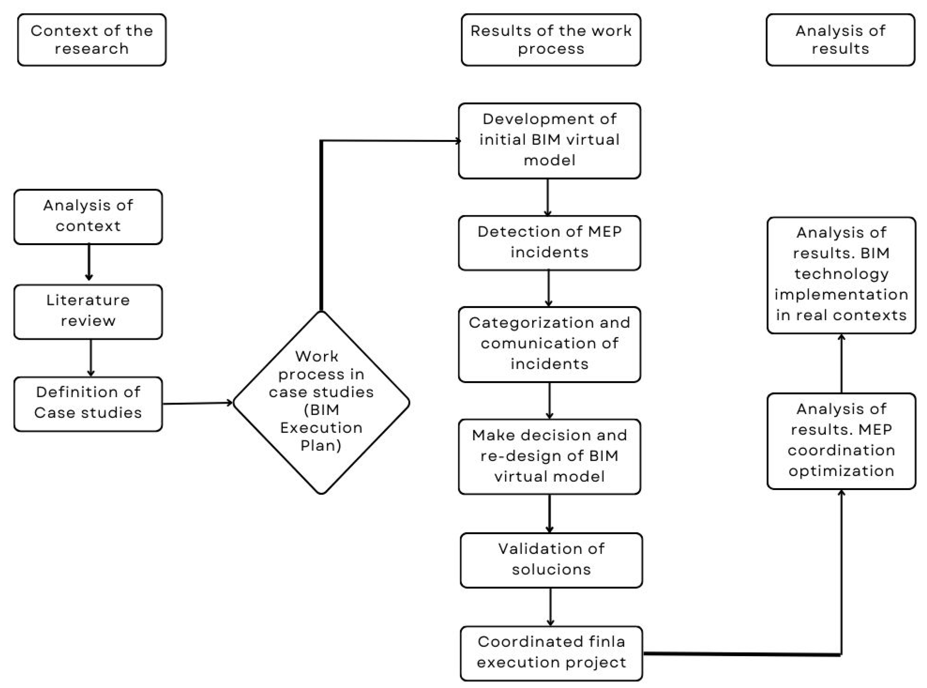
In this context, the research methodology to be implemented follows the scheme indicated in Figure 1, divided into three fundamental steps: the definition of the research context, objectives and case studies; the development of the work process to implement BIM as a tool for optimizing MEP facilities in real cases of the construction industry; and the analysis of results achieved in a double line:
- Definition of improvements in the process of coordinated design of MEP facilities;
- Conclusions about the implementation of this methodology in a real context.

Figure 1.
Flow chart of the research methodology.
Figure 1.
Flow chart of the research methodology.
4. Results
From the work carried out in the case studies indicated, we can extract the following results:
4.1. Development of BIM Model from Base Execution Project (PEB)
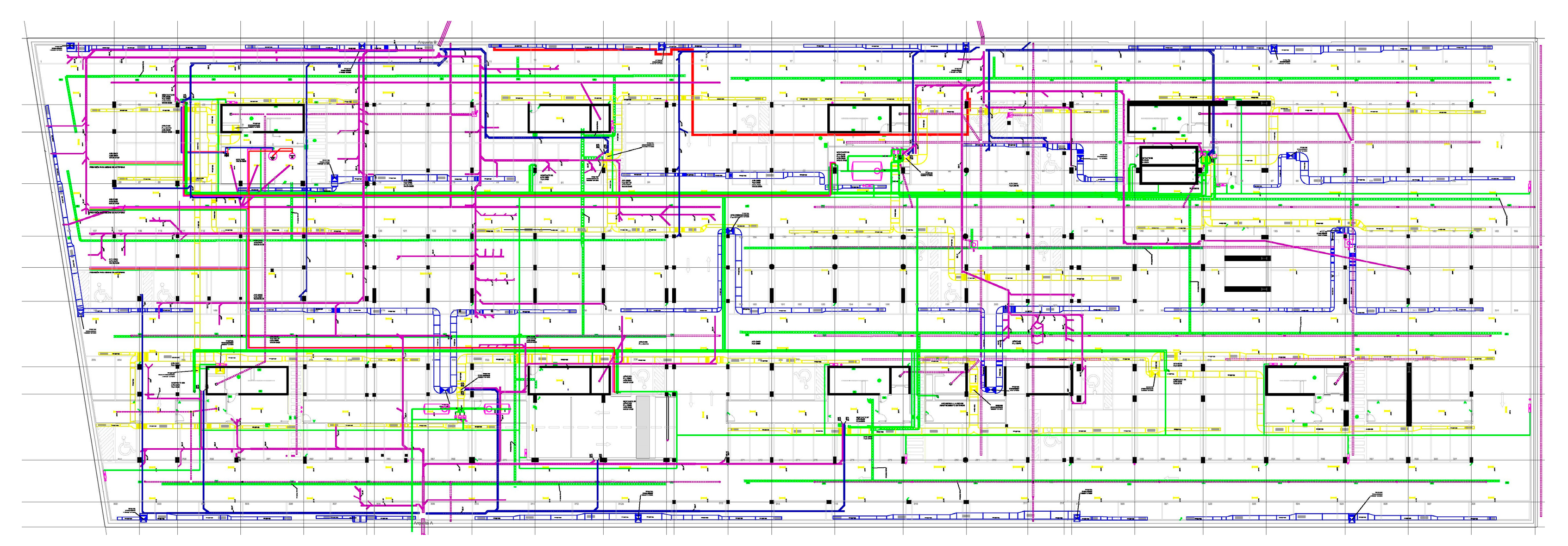
The first milestone of the work plan (H0) focuses on the delivery of the base execution project documentation by the Design Team to the BIM Modeling Team. Figure 2 shows planimetry from the base execution project to be coordinated. They analyze the information received, mainly planimetry in DWG and PDF format (H1) to organize the BIM work (H2), and define the appropriate structure to develop the model, organizing it in sets, files and layers. Therefore, specific modeling assistants are developed for the project—that is, a catalog of reference constructive elements that contains information, what in BIM is called attributes, and a geometric and alphanumeric code that identifies and classifies it—so that all modelers can work with a common database of constructive elements.
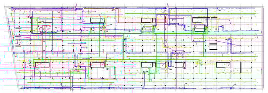
Figure 2.
MEP planimetry from the base execution project (PEB).
In this way, a BIM model is developed, including all geometry and initial information associated with the constructive elements represented. This model is divided into three sub-models: architecture; structure; and MEP facilities. In turn, these are subdivided into independent models that collect each of the specific disciplines contained in these three, which in the case of MEP facilities include: mechanical installations (ventilation and air conditioning); electrical installations (electricity and telecommunications); and plumbing installations (plumbing and sanitation). The multi-file structure of the program allows this distinction between disciplines. In addition, the model is organized in separate files by floor, and within these the hierarchy of layers guarantees the control of the visualization of elements in each of these files [36].
Thus, the visual control of the model is completed with the definition of “representation options”, which allows one to assign textures to the different constructive elements of the model. Therefore, it is possible to achieve a representation with different colors to distinguish elements properly or cause them to acquire an image similar to the real ones, so that anyone without technical knowledge can easily understand what is represented by the model.
The model developed faithfully collects the content of the PEB project, so that although interferences are already detected in the modeling process itself, these are maintained for analysis in the subsequent phase of incident detection and analysis by the BIM Manager [37].
Despite the work being divided into sub-models by discipline, this work is integrated into a single BIM model in which all disciplines can be visualized three-dimensionally together [38]. For this, and although the software used to develop the model is Allplan (Nemetschek group), in the case of architecture and structure and DDS-CAD (of the same group) for MEP facilities, the final files are exported to an open data format (OPEN BIM) called IFC (Industry Foundation Class), so that the exchange of data with other applications can be guaranteed, such as Solibri Model Checker, selected by the BIM Manager as a tool for model revision.
In this way, at the end of this phase of work (H2), the BIM Modeling Team delivers, following the workflow established in the BEP, the complete BIM model of structure, architecture and MEP, in IFC 2 × 3 format (industrial standard), represented in Figure 3.
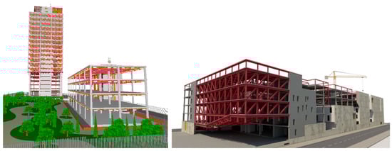
Figure 3.
BIM model of Torre Isla Chamartín (left) and BIM model City of Justice of Cordoba (right), developed by BIM Modeling Team, Total BIM Consulting.
4.2. Analysis of Incidents from the BIM Model
From the elaborated model, the BIM Manager starts the revision process (H3). As noted, the exchange format is IFC (Industry Foundation Class), developed by the IAI (International Alliance for Interoperability), which would later become building SMART. It is a standard for the exchange of information [39] between BIM teams that use different software for the development of their models [40], guaranteeing the interoperability of data [41] when moving from one computer program to another within the BIM process [42]. To carry out the process of revision of the model, the following procedure is established.
- Obtaining IFC exchange files of each model, by discipline, from the native BIM files elaborated, in this case in Nemetschek software [43].
- Combination of IFC files, through the Solibri Model Checker program, to obtain a combined file with SMC (Solibri Model Checker) extension for the 3D visualization of all disciplines together.
- Visual review of the model through “virtual visits” that allow one to detect, by observation, incidents and conflicts between disciplines of the Project.
- Search for incidents in the model by establishing compliance with rules of proper operation in Solibri Model Checker [44].
In this way, the Project Manager can carry out the inspection following two routes of work: visual inspection through virtual tours, and the analysis and auditing of the models in SMC format, with the establishment of rules in Solibri Model Checker. Through this double analysis, we can detect different types of incidents: some by direct visualization in the model (collision between facilities, lack of space, etc.), and others obtained by introducing compliance rules to the Solibri program, which in the case of MEP facilities include three fundamental rules:
- Detection of elements that collide with each other (MEP elements with each other or with architectural or structural elements).
- Detection of MEP elements that do not leave an adequate free passage height, according to regulations (2.20 m).
- Detection of MEP elements that do not have the adequate passage space in false ceilings, regarding the opening of doors and windows, etc.
Under these rules, five main types of incidents are detected (H4):
- Collision between elements of the same family of facilities: this type of interference usually occurs due to a lack of information in the planimetric documentation provided, or due to a lack of coordination in the height of the location of the different elements of the installation. Some examples are shown in Figure 4.
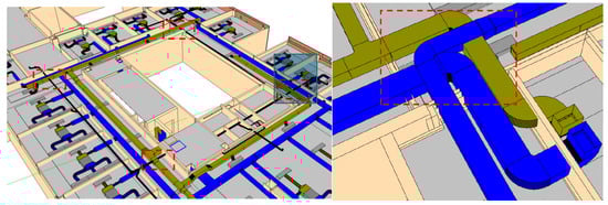 Figure 4. Virtual representation of collision between air conditioning ducts in different scales. BIM Model. The general view (left) and the deailed view (right).
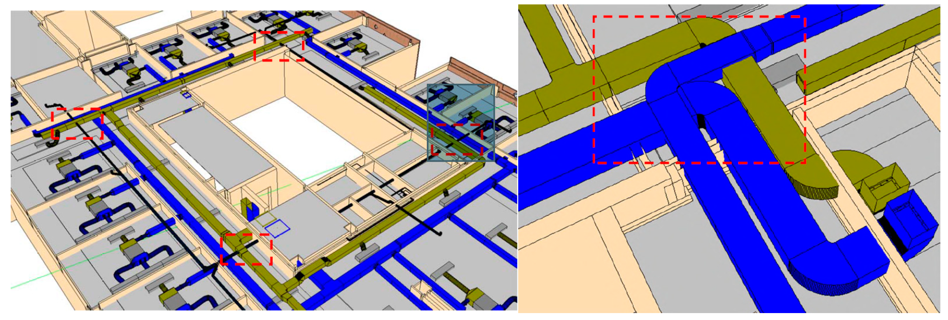
 - Collision between elements of different families of facilities: since in the initial MEP design a coordination work between facilities is not carried out, interferences between them are detected due to the lack of definition of the height of their components, as well as the lack of space for the passage of several installations in parallel. Some examples are shown in Figure 5.
 Figure 5. Virtual representation of collisions between ventilation ducts and plumbing pipeline at different height (left) and parallel collision (right). BIM Model.
 - Collision of facilities with architectural and structural elements: the lack of coordination of MEP installations with these other disciplines causes problems for the proper passage of facilities through constructive elements. Some examples are shown in Figure 6.
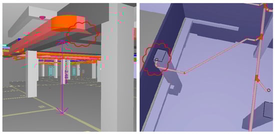 Figure 6. Virtual representation of collision between structural elements and facilities. Ventilation ducts and beam (left) and plumbing pipeline and pilar (right). BIM Model.
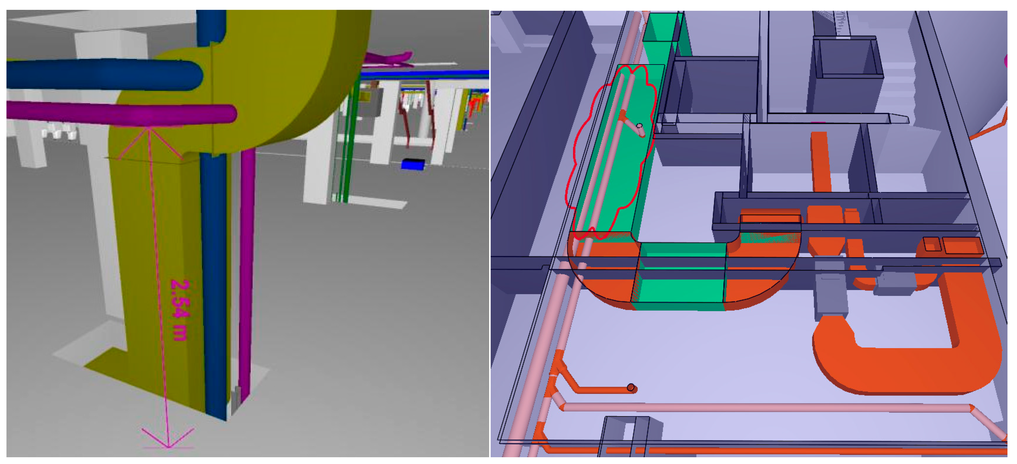
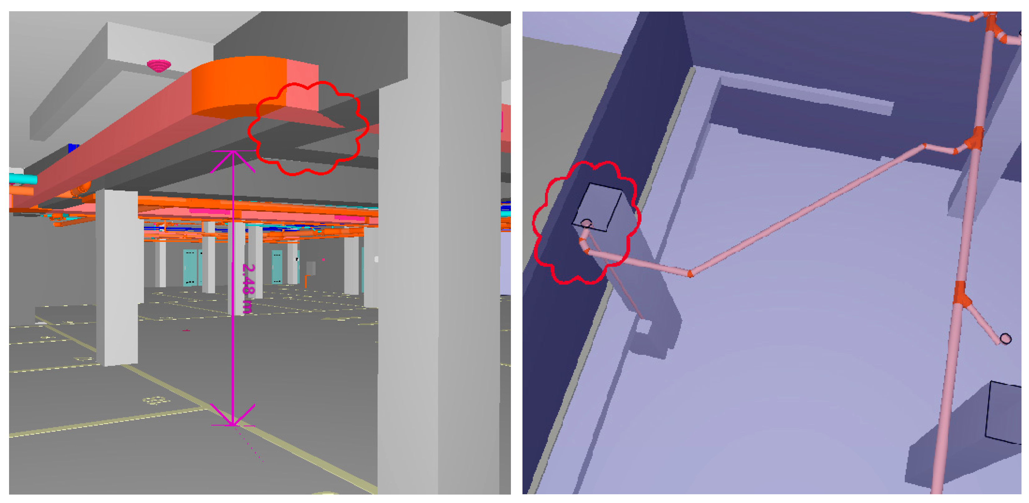
 - Habitability problems caused by MEP design errors: the lack of definition of the height of MEP elements and the dimensional imprecision of these networks cause problems of insufficient height or width of passage in different rooms of the building that compromise their habitability and correct functioning for the use assigned to them. Some examples are shown in Figure 7.
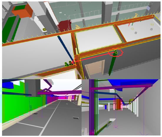 Figure 7. Virtual representation of problems of a lack of height or habitability for MEP design error. Problems of coordination between architectural elements and plumbing pipeline (above) and problems of height with plumbing pipeline (below). BIM Model.
 - Modeling problems: modeling errors are detected that are not project failures and do not require decision making. Some examples are shown in Figure 8.
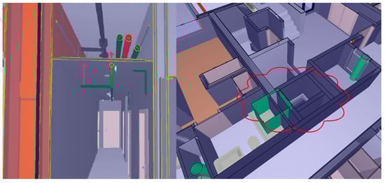 Figure 8. Virtual representation of modeling problems, presenting a plumbing pipeline in a lower position than defined (left) and a ventilation duct out of position (right). BIM Model.
After classifying the main incidents detected, we can indicate the average percentage of the total incidents detected in both study cases that each of them represents, as Table 3 shows, in order to define the most representative ones.
Table 3.
Typification of incidents detected.
As we can see, the collision between elements of different disciplines (facilities, structure and architecture) represents the highest percentage of incidents detected, showing the contribution of the BIM model to the adequate coordination of the project.
4.3. Communication of Incidents and Re-Design Phase
Once the BIM model has been reviewed, multiple conflicts between the structure, architecture and MEP facilities are detected. At this point, it is necessary to re-design new solutions to solve them before the start of the construction phase. Therefore, the BIM Manager, according to the workflow established in the BEP, proceeds to communicate these problems to the Design Team and Developer, in order to define alternative proposals for the design of the MEP facilities that guarantee the resolution of these problems (H5) [45].
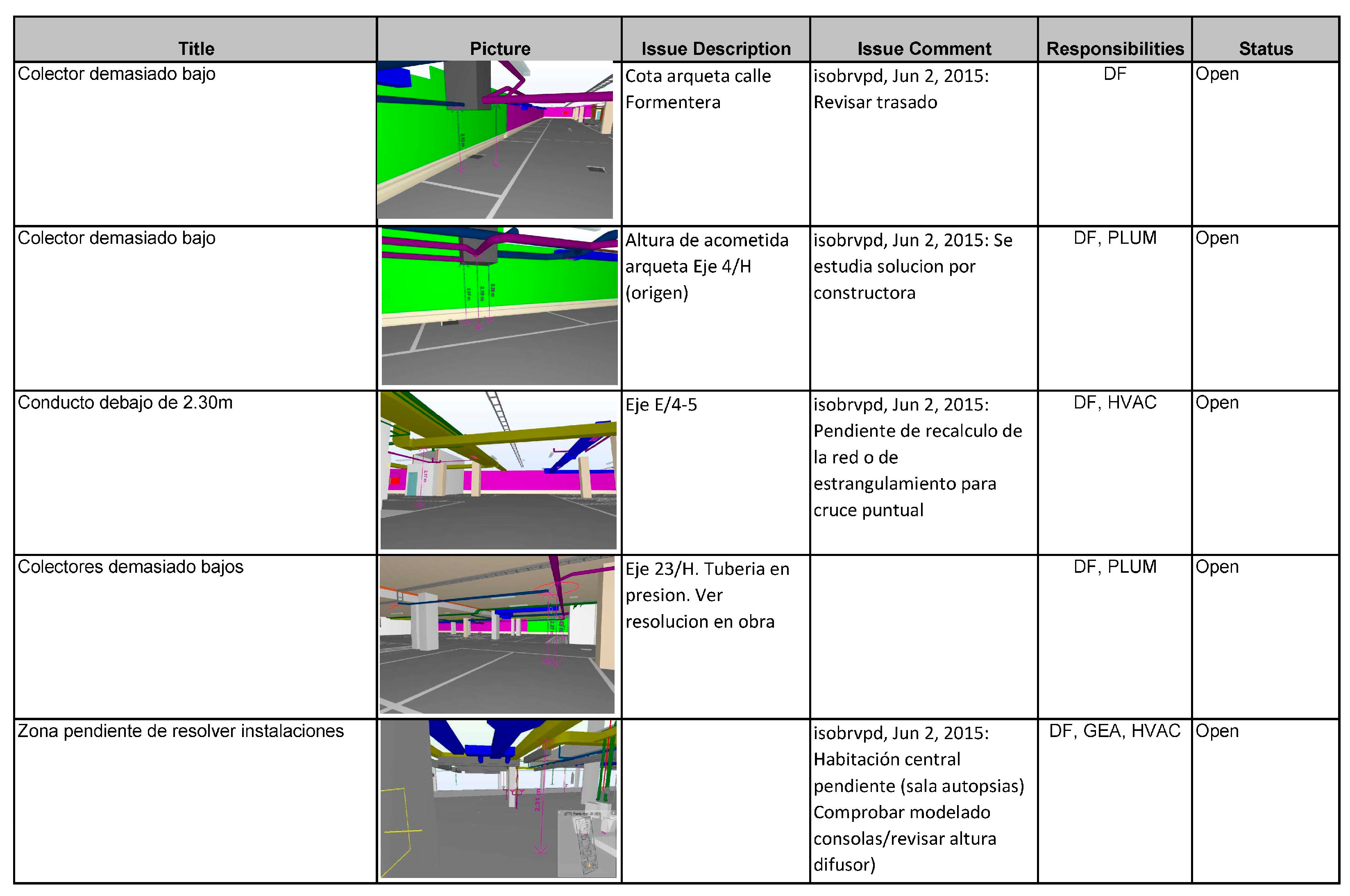
Thus, once the BIM Manager detects an incident, they transfer it through a report within the communication module of the Solibri Model Checker program, in which the agent responsible for its review is indicated (usually to the Design Team). Figure 9 represents some examples of incidents and their communication between agents involved.

Figure 9.
Information elaborated by BIM Manager to communicate incidents to all agents. Solibri Model Checker module of communication.
At that point, the Design Team decide on the re-design solution to solve the problem, and transfer it to the Developer, so that they can accept or reject the change. If it is rejected, the Design Team will have to propose new alternatives until one of them is accepted. Once accepted, the re-design proposal is transferred to the PEB and sent back to the BIM Modeling Team to incorporate it into a revised BIM model [46].
This work process is repeated with all incidents detected, until finally all of them are solved and transferred to the revised BIM model (H6).
This model is exported to IFC files to transfer it to the BIM Manager for a new review (H7) when:
- The BIM Manager can detect incidents pending, because the proposed solution has not resolved the problem or because there have been errors in the modeling process.
- The BIM Manager can detect new incidents, because the re-design proposals produce new problems that did not exist before.
- All incidents have been resolved and no new ones appear, so the model is considered closed.
Whenever incidents continue to appear, the process of communicating them described above is repeated until all are resolved. At that time, the revision process and the BIM model developed are closed.
4.4. Obtaining Coordinated Documentation of the BIM Model
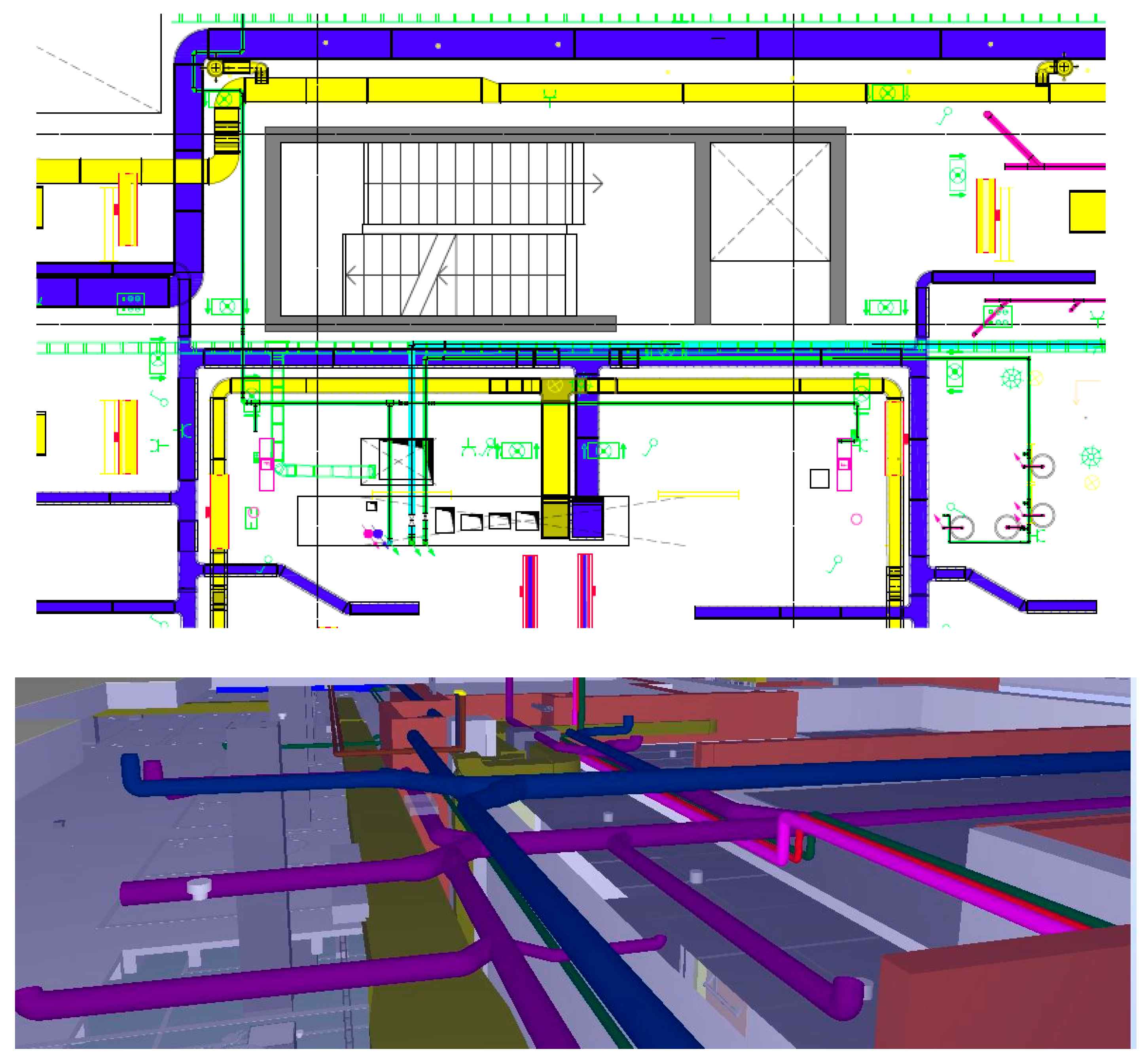
Once the incidents have been resolved, the BIM model is considered closed and the necessary documentation for the correct execution of the construction phase can be obtained from it (H8)—in this case, measurements and planimetry from the Final Execution Project (PED). It is important to note that this new planimetry collects the information provided by the model, incorporating it with the original two-dimensional information at the altimetric level of each element of the MEP facilities, as Figure 10 shows. In this sense, the BIM model should become a working material used in the development process of the construction [47], serving as a virtual prototype for consultation and support to search for the three-dimensional visualization of the agreed solutions [48], as Figure 11 shows.
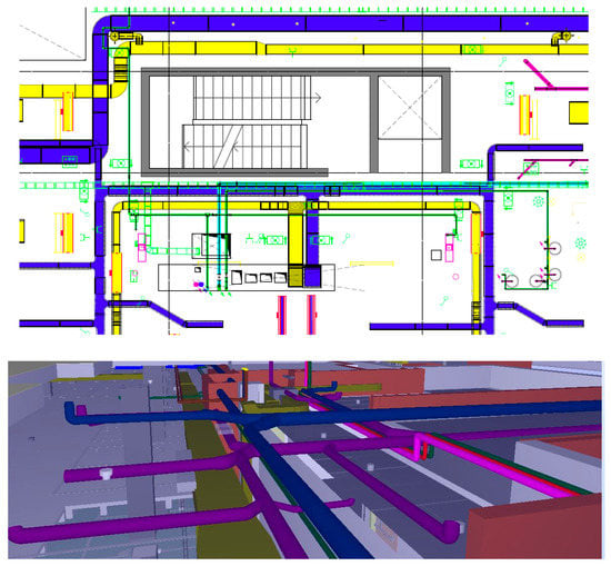
Figure 10.
MEP coordinated planimetry obtained from the BIM model (above), and the associated 3D model view (below). Final execution project (PED).
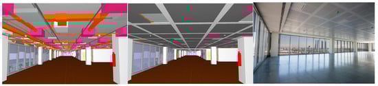
Figure 11.
Representation of the BIM coordinated model of facilities (left), with architectural elements (center), and the final image of the built real space (right).
All of this coordinated documentation allows the building to be constructed more efficiently, avoiding the appearance of problems already detected and solved in this BIM coordination process. This facilitates the elimination of budgetary deviations that these problems usually cause.
At the same time, at the end of the modeling process, measurement lists of the different items included in the project are obtained from the same one, which allows for controlling, based on the BIM model, the cost of the works.
4.5. Practical Implications of the Implementation of the BIM Methodology in Real Projects
Based on the results achieved, we point to the key information that these experiences provide us in terms of the implementation of BIM work procedures for the optimization of MEP facilities in the development of execution projects in a real context. To do this, we make a distinction between two key aspects: first, the benefit that the procedure provides to improve the design of the facilities; and second, key information for the implementation of this type of methodology (BIM Execution Plan) among the agents involved in the projects analyzed as a way of expanding of this technology in the construction industry.
Thus, regarding the first aspect, we can point out that the defined work process helps the designed facilities to be optimized, avoiding conflicts with architectural and structural elements and those associated with the facilities themselves, which avoids costs in the construction phase of the works.
However, the automation process of detecting these conflicts is not as effective as it should be, since many collisions that are due to errors or the inaccuracy of modeling are detected automatically, making it difficult to detect actually conflicting interferences. Therefore, the work of the BIM Manager in this type of process is fundamental, since they are the agent in charge of selecting the important incidents in reality.
In turn, the failures in automation and the necessary involvement of agents in conflict detection causes the design and decision-making process to be prolonged, lengthening the times defined for the development of the design project, which are not as effective as they should be. However, the intervention of the different agents in this decision-making process, following the workflow defined in the BIM Execution Plan, means that the solutions adopted are coordinated and that all the incidents detected and solved will not pose a problem in the construction phase.
On the other hand, from the point of view of the implementation of this work methodology for the agents involved in real projects, we can point out that initially the work process is perceived as an advancement that facilitates the optimization of the installation and avoids problems on site. However, the time consumed by automation failures in the detection of incidents and the extension of deadlines for the closure of the design process mean that this work methodology involves delays that, in general, are not well received by developers and builders, which makes it difficult for this type of technology to spread in the construction sector.
In turn, many of the agents involved in the process do not master the use of BIM technology, which is also a handicap when using this method of work. However, the three-dimensional visualization of MEP facilities is a point in favor of this methodology for the agents involved, since it is easy for them to understand the process and make decisions. Additionally, the BIM manager becomes a key figure for his knowledge of this technology, and serves as a support for the rest of the agents.
Therefore, despite the fact that the results achieved after the process of coordination of MEP facilities through virtual BIM models is satisfactory, allowing one to solve important incidents, bring forward deadlines, and reduce costs in the execution phase of the work, the promoters, both public and private, can detect a failure in the automation of the detection, which causes delays in the design process and hinders the implementation of this type of technology in real development projects.
5. Discussion
The implementation of these two experiences of the optimization of MEP facilities through the development of virtual BIM models points to key aspects pointed out by previous research, such as that the definition of a clear workflow between the agents involved in these processes, which facilitates the coordination of disciplines and the results achieved [12]. At the same time, it highlights the need to optimize automation in the detection of collisions between elements of the virtual model in order to achieve design phase times, improve productivity and thus facilitate the dissemination of this technology among agents in the architecture, engineering and construction sectors, in line with those raised by research such as [15], or [18]. Based on this aspect, different investigations have made contributions of interest, although it is necessary to deepen those that simplify the process of work and crossing of information, such as the model proposed by [16], with graphical simplification.
Along this line, the set of incident verification rules used by Solibri Model Checker software is taken as a reference base of the study, which is similar to bases such as the defined by the research of [19], as a complement to the REVIT platform to simplify the analysis of the real situation of the building. The simplification of the BIM model for the performance of incident analysis can be done through algorithmic mapping too, as a way to improve the efficiency of exchange processes, in line with research such as that of [22].
Automation will also be linked to the ability of the BIM environment to serve as a common information management platform for the different agents involved in the design process. In this way, facilitating the interoperability of information between different software, as well as the transfer of data to cost management or energy analysis programs, can help to simplify the design work, in line with researchers such as [33], or [36].
This search for simplification is an essential task to facilitate the implementation of BIM work methodologies in the construction sector, taking into account the fact that, for the moment, many of the personnel associated with this sector are not experts in the management of this technology. Simplifying the work and visualization environment will also contribute to achieving this goal, as Alizadehsalehi pointed out in his research on linking BIM and virtual reality. Linking this technology with the monitoring of the installation associated with the maintenance of MEP installations throughout the life of the building supports the existence of BIM models and encourages developers to develop them from the design phase.
In this way, considering the future use of the BIM virtual model as a tool to monitor the different MEP facilities in the maintenance phase of the building can help to give greater value to the initial time invested to develop the BIM model in the design phase, in order to be profitable in later phases. Therefore, the BIM virtual model will seek to integrate virtual reality technologies [30] already researched, such as the use of sensors to predict the behavior of facilities throughout its useful life [23], the integration of intelligent building technologies [13] or the generation of data from point clouds (Wang et al., 2021). In this way, the virtual modeling of MEP installations carried out in the design phase will facilitate the improvement of the resilience of this equipment, improving maintenance work when failures appear [17].
Therefore, the implementation of theoretical concepts that this study tries to carry out in two real practical cases allows us to conclude that the development of lines of research opened by other researchers to optimize the work process and coordination in the BIM environment are key to ensuring that this technology expands and has a place in the construction sector as we know it today. The improvement of automation processes and the simplification of work processes are essential to guaranteeing the bringing forward of deadlines and the profitability of this technology for the sector.
Additionally, the work carried out around these two case studies allows us to extract key information that helps to improve this work protocol for the implementation of this technology in the construction sector:
- Modeling work using BIM facilitates the three-dimensional representation and visualization of projects. The fact that the model allows one, in a simple way, to work three-dimensionally with different disciplines, and in this specific case with the MEP facilities, makes it easy for the different agents involved in the design process to detect, in a visual way, collisions that would not be possible with two-dimensional and individual design work. Therefore, working with the BIM methodology, as already mentioned, facilitates coordination between disciplines and agents involved in the project.
- The presence of a BIM Manager and a BIM Execution Plan allows one to deepen this review process. While the work in BIM facilitates the coordination and resolution of incidents by visualization, having an agent dedicated to the exhaustive analysis of models, not only visually but through mathematical rules of compliance with design criteria, facilitates the task of the coordination and resolution of a greater number of incidents before the start of the construction phase.
- The incidents detected in these experiences, and which have been previously typified, respond fundamentally to two issues: modeling problems by the BIM Modelling Team, either by error or due to a lack of information in the reference PEB project, and PEB design errors that require re-design solutions.
- In the first case, a large number of incidents due to modeling errors were initially detected, which were mainly due to the lack of information in the documentation associated with the PEB. Although they were easily solved and did not require re-design solutions, they would have created confusion during the construction phase. Thus, solving them in this process ensures that the information associated with the project is conducted without error for other agents.
- In the case of incidents due to design errors, their detection in this process of analysis allows the work to not be stopped during the phase of construction of the building, as there is no need to wait for the Design Team to make appropriate re-design decisions, with its consequent increase in execution time and an increase in costs.
- Despite the many advantages pointed out, working with BIM technology requires a lot of precision and long development deadlines that, in the construction industry, tend to be shorter. This means that these modeling and revision processes are not as exhaustive as they should be, and consequently are not effective enough.
The implication of these results leads us to understand that BIM is a methodology that offers clear advantages for the construction industry, since it involves anticipation in the detection of incidents between MEP disciplines that can be optimized in the design phase, avoiding problems in the construction phase, cost overruns and increased deadlines.
However, there are aspects that hinder the implementation of this technology in a broad way: on the one hand, it is a complex technology, for which many personnel in the sector do not have training; it is a technology that still requires improving its automation to really be effective in the rapid detection of conflicts, since it now requires a temporary involvement that increases the deadlines of the design process.
These issues, however, can be optimized under different approaches: first, to have a BIM manager and a BIM Execution Plan which facilitates the work of non-family personnel with BIM technology; seeking mechanisms to simplify virtual models to facilitate the work of these unqualified personnel as well as automation in conflict detection, following methods exposed by researchers mentioned above; facilitating the interoperability of data between different software that allow us to carry out cost or energy analysis in an efficient and automated way; considering the time invested in the design phase an investment that will pay off by implementing virtual reality and monitoring technologies in these virtual models, in order to facilitate their use in the maintenance phase of the building.
Therefore, the experiences analyzed serve to point us towards those aspects that will contribute to this type of technology being profitable for the construction industry and gradually expanding as a working methodology in this sector.
6. Conclusions
Therefore, from the analysis of successful cases in the development of virtual BIM models for the coordination of MEP facilities in complex building projects, we can conclude that this methodology allows one to anticipate conflicts between the different disciplines (structure, architecture and facilities), ensuring the effective MEP design, as well as the adequate forecast of spaces for the passage of facilities and equipment in a comprehensive and collaborative design process between different agents. At the same time, the 3D model ensures that the graphic documentation used is kept up to date, and incorporates additional information in addition to traditional information, usually altimetric. In this way, problems are avoided in the execution phase of the construction, avoiding the need for deadlines to be extended and additional costs, and facilitating the management and administration of the work.
Therefore, it is a suitable technology for the optimization of MEP installations in the design phase prior to the execution of the works. However, regarding what the implementation of BIM methodology entails in real cases associated with the construction sector, we can conclude that, although the benefits achieved are valued by most of the agents involved, there is a general perception that this type of process complicates the design work and supposes an initial extension of deadlines that is not easy to assume despite the subsequent savings in costs and deadlines involved in avoiding conflicts in the construction phase. Additionally, we will indicate as positive aspects to incorporate to the development of this kind of projects the need to have a well-planned BIM Execution Plan and a BIM Manager that serves as support for the entire process.
In this way, this article contributes to the field of knowledge in which it resides by pointing to key aspects that require improvement to facilitate the implementation of this technology in the construction sector, such as collision detection automation to bring forward deadlines in the design process and the search for work systems in the BIM environment that facilitate the incorporation of non-expert agents. We can point to these aspects as lines of future work to bring the use of this technology into professional practice. It is also important to point out the need to improve the ways of introducing this technology to professionals in the training phase too.
As limitations of the study, however, we can point out that, in the two cases analyzed, it is difficult to quantify the savings produced with the introduction of this methodology, since the start of the BIM design process was postponed until phases very close to the start of the execution of the works. Associated with this limitation, we can point out as a line of future work the need to quantify the savings that this type of process provides for a work, both economically and in terms of deadlines. An effective quantification that reveals the real profitability of this type of process would help it to spread in the construction sector, making the coordination between disciplines and MEP optimization very attractive for the sector.
Funding
This research received no external funding.
Institutional Review Board Statement
Not applicable.
Informed Consent Statement
Not applicable.
Data Availability Statement
Not applicable.
Acknowledgments
This study has been carried out thanks to the developers of both projects, the participation of all agents involved in them, and the work of TotalBIM Consulting as the BIM Modeling Team of the process.
Conflicts of Interest
The authors declare no conflict of interest.
References
- Oliver Faubel, I. Integración de la Metodología BIM en la Programación Curricular de los Estudios de Grado en Arquitectura Técnica/Ingeniería de Edificación. Diseño de una Propuesta. Ph.D. Thesis, Universitat Politècnica de València, Valencia, Spain, 2016. [Google Scholar]
- Analia Alejandra, Á.; Verónica Ripoll Meyer, M. Propuesta para la implementación de la metodología BIM en una experiencia áulica orientada a la sustentabilidad edilicia. Rev. Hábit. Sustentable 2020, 10, 32–43. [Google Scholar]
- Chimeno, C.; del Rosario, M.; Rodríguez, J.F.F.; Quiñones, R. Bases metodológicas para el uso de tecnología bim como herramienta de simulación energética en rehabilitación. In Congreso Internacional de Construcción Sostenible y Soluciones Ecoeficientes (1°. 2013. Sevilla); Departamento de Construcciones Arquitectónicas I, Universidad de Sevilla: Seville, Spain, 2013. [Google Scholar]
- AIA+S. Aula de Investigación de Arquitectura Sostenible. Available online: http://aiasostenible.blogspot.com/2009_04_01_archive.html (accessed on 15 December 2022).
- Garcia, M.; Augusto, G. Interoperabilidad en el Entorno BIM: Mejoramiento de los Procesos de Diseño y Comunicación a Partir de la Implementación del Concepto OpenBIM. Ph.D. Thesis, Universidad Nacional de Colombia, Manizales, Colombia, 2020. [Google Scholar]
- Blank Leland, T.; Tarquin, A.J. Basics of Engineering Economy; McGraw-Hill Higher-Education: New York, NY, USA, 2008. [Google Scholar]
- Valdivia, D.; Carlos, J. Implementación de Tecnología Bim-Vdc para la Gestión del Diseño y Construcción de Instalaciones Mecánicas Eléctricas, caso Retail Restaurantes Ekeko, Arequipa 2017–2018. Ph.D. Thesis, Universidad Católoca de Santa María, Arequipa, Perú, 2019. [Google Scholar]
- Torres, M.; María, A. BIM y las Repercusiones en la Calidad de los Procesos Constructivos: Análisis Sobre la Influencia de esta Metodología en las Etapas del Proceso Constructivo. Ph.D. Thesis, Universitat Politècnica de Catalunya, Barcelona, Spain, 2015. [Google Scholar]
- Murcia, P.; Domingo, A. Análisis Mediante BIM del Proyecto de Ejecución de una Vivienda Unifamiliar Entre Medianeras. Ph.D. Thesis, Universitat Politècnica de València, Valencia, Spain, 2016. [Google Scholar]
- Giner, F.; Begoña, M.; Faubel, I.O. EUBIM. Encuentro de usuarios BIM 2014. In Proceedings of the 2° Congreso Nacional BIM, Valencia, Spain, 23–24 May 2014. [Google Scholar]
- Alzate, S.; Fernando, M. Impacto Económico del uso de BIM en el Desarrollo de Proyectos de Construcción en la Ciudad de Manizales; Facultad de Artes: Seoul, Republic of Korea, 2017. [Google Scholar]
- Parti, R.; Hauer, S.; Monsberger, M. Process model for BIM-based MEP design. In IOP Conference Series: Earth and Environmental Science; IOP Publishing: Bristol, UK, 2019; p. 012045. [Google Scholar]
- Han, J.; Zhou, X.; Zhang, W.; Guo, Q.; Wang, J.; Lu, Y. Directed representative graph modeling of MEP systems using BIM data. Buildings 2022, 12, 834. [Google Scholar] [CrossRef]
- Wang, B.; Yin, C.; Luo, H.; Cheng, J.C.; Wang, Q. Fully automated generation of parametric BIM for MEP scenes based on terrestrial laser scanning data. Autom. Constr. 2021, 125, 103615. [Google Scholar] [CrossRef]
- Hu, Y.; Xia, C.; Chen, J.; Gao, X. Clash context representation and change component prediction based on graph convolutional network in MEP disciplines. Adv. Eng. Inform. 2023, 55, 101896. [Google Scholar] [CrossRef]
- Wang, Y.; Zhang, L.; Yu, H.; Tiong, R.L. Detecting logical relationships in mechanical, electrical, and plumbing (MEP) systems with BIM using graph matching. Adv. Eng. Inform. 2022, 54, 101770. [Google Scholar] [CrossRef]
- Wang, Y.; Lin, P.; Zhang, L.; Yu, H.; Robert, T.L.K. Resilience-oriented design for complex MEP systems in BIM. Adv. Eng. Inform. 2023, 55, 101902. [Google Scholar] [CrossRef]
- Teo, Y.H.; Yap, J.H.; An, H.; Yu SC, M.; Zhang, L.; Chang, J.; Cheong, K.H. Enhancing the MEP Coordination Process with BIM Technology and Management Strategies. Sensors 2022, 22, 4936. [Google Scholar] [CrossRef] [PubMed]
- Xie, X.; Zhou, J.; Fu, X.; Zhang, R.; Zhu, H.; Bao, Q. Automated rule checking for MEP systems based on BIM and KBMS. Buildings 2022, 12, 934. [Google Scholar] [CrossRef]
- Sepehr, A.; Ahmad, H.; Joseph Chuenhuei, H. From BIM to extended reality in AEC industry. Autom. Constr. 2020, 116, 103254. [Google Scholar]
- Sepehr, A.; Ibrahim, Y. Digital twin-based progress monitoring management model through reality capture to extended reality technologies (DRX). Smart Sustain. Built Environ. 2023, 12, 200–236. [Google Scholar]
- Li, H.; Zhang, J.; Chang, S.; Sparkling, A. BIM-based object mapping using invariant signatures of AEC objects. Autom. Constr. 2023, 145, 104616. [Google Scholar] [CrossRef]
- Cheng, J.C.; Chen, W.; Chen, K.; Wang, Q. Data-driven predictive maintenance planning framework for MEP components based on BIM and IoT using machine learning algorithms. Autom. Constr. 2020, 112, 103087. [Google Scholar] [CrossRef]
- Miguelangel Gea, A. Un caso de éxito: Ciudad de la Justicia de Córdoba (España). Span. J. Build. Inf. Model. 2015, 15, 18–28. [Google Scholar]
- Metalocus. Available online: https://www.metalocus.es/en/news/mecanoo-architecten-completed-cordoba-palace-justice (accessed on 15 December 2022).
- Arquitectura Viva. Available online: https://arquitecturaviva.com/obras/ciudad-de-la-justicia-de-cordoba (accessed on 10 December 2022).
- Cercha. Revista de la Arquitectura Técnica. Available online: https://www.cgate.es/cercha/pdf/134.pdf (accessed on 10 December 2022).
- Portal Web Del Ayuntamiento de Madrid. Available online: https://www.madrid.es/portales/munimadrid/es/Inicio/Actualidad/Noticias/Entra-en-funcionamiento-la-nueva-salida-a-la-A-1-desde-la-Isla-de-Chamartin/?vgnextfmt=default&vgnextoid=7a77a6b94b102810VgnVCM1000001d4a900aRCRD&vgnextchannel=a12149fa40ec9410VgnVCM100000171f5a0aRCRD (accessed on 10 December 2022).
- Web AE3 Técnicos Asociados. Available online: https://ea3.es/proyecto/isla-chamartin/ (accessed on 10 December 2022).
- Rojas, A.; Alonso, C. Análisis de la Implementación de la Metodología BIM Para la Optimización del Proyecto de Construcción de Centro Cívico en el Barrio Huanuquillo-Tarma. Ph.D. Thesis, 2019. [Google Scholar]
- El Economista: ¿Qué es un BIM Manager? Available online: http://blogs.eleconomista.net/tecnologia/2018/10/que-es-un-bim-manager-10-puntos-de-un-oficio-con-futuro/ (accessed on 5 December 2022).
- Management y Empleo. Available online: https://gestion.pe/economia/management-empleo/bim-manager-10-puntos-debes-oficio-futuro-247844-noticia/ (accessed on 5 December 2022).
- Miguelangel Gea, A. Open BIM: Los archivos IFC en la gestíon de la obra de la Ciudad de la Justicia de Córdoba (España). Span. J. Build. Inf. Model. 2015, 15, 20–34. [Google Scholar]
- Pizarro, A.; Sofia, A.; Arrieta, J.R.S. Building Information Modeling (BIM) y su Desarrollo en la Industria de la Construcción. Ph.D. Thesis, Universidad Nacional de Piura, Piura, Perú, 2022. [Google Scholar]
- Zigurat. Available online: https://www.e-zigurat.com/blog/es/bim-execution-plan-bep-cuando-se-utiliza/ (accessed on 15 December 2022).
- Pérez Galvín, A.; Barbudo Muñoz, M.A.; Ayuso Muñoz, J.; García Beltrán, M.; Rosales García, J.; López Uceda, A. Introducción al modelado de información de construcción (BIM) en edificaciones e infraestructuras de ingeniería. Rev. De Innovación Y Buenas Prácticas Docentes 2019, 8, 107–115. [Google Scholar] [CrossRef]
- de las Marinas, V.P. La experiencia BIM de la Ciudad de la Justicia de Córdoba. Rev. De Obras Públicas Organo Prof. De Los Ing. De Caminos Canales Y Puertos 2018, 3597, 46–53. [Google Scholar]
- Polanco Guerra, S. Acercamiento a la Tecnología BIM. Software Cype Aplicado a Proyectos de Ingeniería en Ccrea, Villa Clara. Ph.D. Thesis, Universidad Central “Marta Abreu” de las Villas, Santa Clara, Cuba, 2019. [Google Scholar]
- González Pérez, C. Building Information Modeling: Metodología, Aplicaciones y Ventajas. Casos Prácticos en Gestión de Proyectos. Master’s Thesis, Universidad Politécnica de Valencia, Valencia, Spain, 2015. [Google Scholar]
- Chacón, D.; Cuervo, G. Implementación de la Metodología BIM para Elaborar Proyectos Mediante el Software Revit. Bachelor’s Thesis, Universidad de Carabobo, Valencia, Venezuela, Carabobo, Venezuela, 2017. [Google Scholar]
- Cachay, A.; Enrique, P.; Cerna, J.A.G.; Esquivel, D.K.I. Aplicación de la Tecnología BIM al Facility Management de un Centro Comercial en el Perú. Ph.D. Thesis, Universidad Peruana de Ciencias Aplicadas, Lima, Perú, 2016. [Google Scholar]
- Rodriguez, M. Integración De Procesos Bim En Levantamiento De Edificios Existentes: Edificio De Laboratorios De La ETSIE Campus Universitario Reina Mercedes. Master’s Thesis, Universidad de Sevilla, Sevilla, Spain, 2015. [Google Scholar]
- Available online: http://blog.entornobim.org/ejemplo-aplicacion-la-metodologia-bim-espana-la-ciudad-la-justicia-cordoba/ (accessed on 1 December 2022).
- BIM Community. Case Studies. Available online: https://www.bimcommunity.com/experiences/load/78/Blank (accessed on 1 December 2022).
- Martínez, A.; Shirley, J. Propuesta de una Metodología Para Implementar las Tecnologías VDC/BIM en la Etapa de Diseño de los Proyectos de Edificación. Ph.D. Thesis, Universidad Nacional de Piura, Piura, Perú, 2019. [Google Scholar]
- Yacolca Vilcapoma, D.R. Implementación de la tecnología Building Information Modeling (BIM) 4d en la ejecución de proyectos de edificación. In Trabajo fin de Estudios en Ingeniería Civil; Universidad de Los Andes: Bogotá, Colombia, 2019. [Google Scholar]
- Coloma Picó, E. Introducción a la Tecnología BIM; Departamento de Expresión Gráfica Arquitectónica I. Escuela Técnica Superior de Arquitectura de Barcelona, Universidad Politécnica de Cataluña: Barcelona, Spain, 2008. [Google Scholar]
- Padilla Marcos, M.Á.; Meiss Rodríguez, A.J. Proyecto IMAI-innovación en la materia de Acondicionamiento e Instalaciones. Plan BIM. In Proceedings of the Libro de Actas del XXVI Congreso Universitario de Innovación Educativa en las Enseñanzas Técnicas, Gijón, Spain, 25–27 June 2018; pp. 210–220. [Google Scholar]


Disclaimer/Publisher’s Note: The statements, opinions and data contained in all publications are solely those of the individual author(s) and contributor(s) and not of MDPI and/or the editor(s). MDPI and/or the editor(s) disclaim responsibility for any injury to people or property resulting from any ideas, methods, instructions or products referred to in the content. |
© 2023 by the author. Licensee MDPI, Basel, Switzerland. This article is an open access article distributed under the terms and conditions of the Creative Commons Attribution (CC BY) license (https://creativecommons.org/licenses/by/4.0/).