Article

Effect of Cementitious Material Composition on the Performance of Low-Carbon Foamed Lightweight Soil

1
School of Materials Science and Engineering, Wuhan University of Technology, Wuhan 430070, China
2
China Construction Second Engineering Bureau Limited East China Branch, Shanghai 200135, China
*
Author to whom correspondence should be addressed.
Buildings 2023, 13(3), 759; https://doi.org/10.3390/buildings13030759
Submission received: 22 February 2023 / Revised: 9 March 2023 / Accepted: 11 March 2023 / Published: 14 March 2023
(This article belongs to the Special Issue Low Carbon and Green Materials in Construction)

Abstract

:
This study simulated the production process of low-carbon foamed lightweight soil (LCFLS) prepared using prefabricated foam technology in real engineering conditions. The preparation and properties of LCFLS with a wet density of 600 kg/m3 were systematically investigated. The effects of different mix designs of large dosing granulated blast furnace slag and fly ash on the properties of LCFLS were investigated. The workability, rheological properties, and mechanical properties of LCFLS were studied. XRD, TG–DTG, and SEM were used to analyze the hydration mechanism of LCFLS. The results showed that fly ash could improve the flowability of LCFLS, while excessive fly ash could lead to foam and slurry delamination. Granulated blast furnace slag improved the mechanical properties of LCFLS, while excess granulated blast furnace slag caused the foam to break and merge, affecting the soil’s homogeneity. The higher the dynamic yield stress of the freshly mixed slurry, the better the homogeneity, and the smaller and more evenly distributed pore sizes formed after hardening. The main hydration products of LCFLS were C-S-H gel and CH, with small amounts of the carbonation products CaCO3, Hc, and Mc. The LCFLS prepared with 30% cement, 30% fly ash, and 40% granulated blast furnace slag had a flowability of 170–180 mm, with slight differences between wet and quasi-dry densities. The rheological properties of the slurry following the Bingham model showed a dynamic yield stress of 9.41 Pa, an average pore size after hardening of around 300 μm, and compressive strengths at 7 d and 28 d reaching 0.92 MPa and 2.04 MPa, respectively.

1. Introduction

Foamed lightweight soil (FLS) is a lightweight cementitious material containing many closed micropores [1]. It is formed by physically preparing an aqueous solution of a foaming agent into foam, and then mixing it with a cement slurry in a particular proportion after natural maintenance [2]. By controlling the amount of prefabricated foam, the density of FLS can be between 300–1800 kg/m3 [3]. FLS has been widely used in housing construction [4], railroad and highway roadbeds [5], military, civil engineering [6], and airport runway end buffer pavement [7] because of its low density, good flowability, easy construction and high strength after hardening [8]. Therefore, FLS is in great demand for practical applications, with dosages generally reaching 100,000 m3 and above [9,10]. Although FLS has a high foam volume, about 60% in the production process, cement consumption must not be underestimated. To meet the concept of “carbon peaking and carbon neutral,” preparing low-carbon foamed lightweight soil (LCFLS) using mineral admixtures instead of cement has become the leading research and application direction.
Research has shown that replacing cement with some granulated blast furnace slag and fly ash reduces the amount of cement, and improves the long-term mechanical properties [11] and durability of cement-based materials [12]. Hang [13] studied the effect of mineral admixtures on the properties of FLS, and found that mixing an appropriate amount of granulated blast furnace slag and fly ash could improve its compressive strength. Kearsley [14] studied the effect of fly ash replacing cement in FLS, and concluded that mixing some fly ash in FLS improved its strength and flowability. In the past, due to the backward technology of synthesis of foaming agents, FLS was prepared with pure cement to meet the requirements [15]. In the last decade or so, with the advancement of foaming agent synthesis technology, the quality of foaming agents and foam has improved significantly [16]. At the same time, much advanced automated equipment for preparing FLS has also emerged [17], making it possible to mix large amounts of mineral admixtures into FLS [18].
Currently, most studies on LCFLS have remained focused at the stage of a single, low-dose mineral admixture. They focus more on the mechanical properties of LCFLSs and their durability. Therefore, a clear understanding of the hydration mechanisms and properties of LCFLS has not yet been developed. In addition, studies on foams have focused on the quality of the foam and its stability in air, as well as on the pore structure formed after hardening. Not much research has been conducted on the presence of foam in fresh slurry, and on the conditions under which it exists. The density of the cementitious material in LCFLS differs significantly from the density of the foam. Moreover, LCFLS has a relatively sizeable water–binder ratio, which is prone to poor situations such as the delamination of slurry during preparation [19,20]. Mixed slurry has a long setting time; the foam may create upwellings during the hardening process and affect the system’s stability [21,22].
This study simulated the production process of LCFLS preparation in actual engineering conditions, and used a miniature intelligent foaming machine for foam preparation in the laboratory. The effects of different mix designs of large dosing granulated blast furnace slag and fly ash on the properties of LCFLS were investigated. The workability, rheological properties, and mechanical properties of LCFLS were studied. XRD, TG–DTG, and SEM were used to analyze the hydration mechanism of LCFLS. Moreover, the stability and homogeneity of the LCFLS in the preparation process were analyzed. Such results document experience in the preparation of LCFLS, and provide feasible ideas for the green and economization of FLC.

2. Materials and Methods

2.1. Materials

The main raw materials used in this study were cement (PC), fly ash (FA), and granulated blast furnace slag (GBFS).
The PC used was PO 42.5 cement. Its chemical composition and physical properties are shown in Table 1 and Table 2, respectively. The GBFS was S95-grade ground slag with a density of 2800 kg/m3 and a specific surface area of 410 m2/kg, and its chemical composition is shown in Table 2. The FA used was Class F Grade II FA. Its density was 2200 kg/m3, its fineness (through a 45 µm square-hole sieve) was 15%, and its chemical composition is shown in Table 2.
The foaming agent was a ready-mixed composite foaming agent, model JY-SRN2, produced by Guangdong Shengrui Technology Company. The foaming solution was diluted to the original agent 100 times with water.

2.2. Sample Preparation

According to the requirements of CECS 249-2008 “Technical Specification for Cast-in-Place Foamed Lightweight Soil” [23], the preparation of LCFLS was divided into three main processes, as shown in Figure 1.
(1) Slurry preparation: weigh the materials according to the mix designs in Table 3. The mixing water was prepared according to a water–binder ratio of 0.65. Setting the stirrer speed to about 150 r/min, the mixture was stirred for 2 min to make the slurry.
(2) Foam preparation: use an intelligent micro foaming machine to prepare foams. The foam was delicate, smooth, and uniform in size, as shown in Figure 1a. A knob was adjusted to change the amount of compressed air pressure, and the density of the prepared foam changed. The foam density used in the experiment was controlled at around 50 g/L, as shown in Figure 1b.
(3) LCFLS preparation: add the prepared foam in (2) to the slurry in (1). Setting the stirrer speed to about 60 r/min, the mixture was stirred for 2 min to produce a uniform slurry. The prepared LCFLS was first measured for flowability and wet density, as shown in Figure 1c,d. Subsequently, the specimen was molded (100 × 100 × 100 mm3) and cured in a curing chamber (20 ± 1 °C, RH 90%) for further testing, as shown in Figure 1e,f.

2.3. Mix Designs and Technical Requirements of LCFLS

The mix designs of LCFLS are shown in Table 3, where the cement dosage was fixed at 30% of the total cementitious material, and the water–binder ratio was 0.65. According to the technical requirements of LCFLS for the road base filling project, its flowability, wet density, and mechanical properties are shown in Table 4.

2.4. Test Methods

2.4.1. Workability Tests

The working properties of LCFLS in this study included flowability and wet density, and the test methods followed the requirements of CECS 249-2008 “Technical Specification for Cast-in-Place Foam Lightweight Soils”. The wet density measurement was determined using the arithmetic mean of the results of three tests. The flowability measurement, and the standard of the lengths of two directions perpendicular to each other measured with calipers 1min after the flow value cylinder was lifted were used as the results, and the arithmetic means were determined via three parallel measurements.

2.4.2. Yield Stress Tests

The yield stress of the LCFLS was determined using a BROOKFIELD model R/S plus Rheometer. First, the shear rate was accelerated from 0 s−1 to 100 s−1 in 60 s and then reduced from 100 s−1 to 0 s−1 in 60 s to determine the dynamic yield stress of the LCFLS. Next, the shear rate was accelerated from 0 s−1 to 1 s−1 over 60 s and then fixed at 1 s−1 for 60 s to determine the static yield stress of the LCFLS [24].

2.4.3. Mechanical Properties Tests

The mechanical properties tests were conducted following the requirements of GB/T 11969-2020 “Test Methods for Properties of Autoclaved Aerated Concrete” [25] and CECS 249-2008. After the specimens reached the specified curing age, the samples’ apparent naturally dried densities (quasi-dry densities) were measured first. Then, the machine (TYE-300D) carried out the compressive strength test, and the loading speed used was 0.1 kN/s.

2.4.4. Hydrate Tests

To observe and analyze the hydration products of LCFLS, intermediate sections of the specimens were taken at the age of curing at 7 d and 28 d and immersed in anhydrous ethanol for subsequent testing. Samples for the XRD and TG–DTG tests required passing through a 63 mm sieve. Specimens with a grain size of approximately 3–5 cm were used for SEM testing.
X-ray diffraction (XRD, D/Max-RB) was used to analyze the crystalline phase composition of the specimens after hydration. The XRD test target was a copper target, and XRD patterns were collected from 5–70° over a range of 2θ, in steps of 0.02° at a rate of 4°/min.
A comprehensive thermal analyzer (TG, STA449F3) was used to determine the specimens’ mass change. The test was conducted in an N2 atmosphere from an ambient temperature of 25 °C to 1000 °C, with a heating rate of 10 °C/min. As a result, the content of the hydration product CH of the cement could be calculated from the following Equation (1):
CH = 74 18   ×   Δ G 1 + 74 44   ×   Δ G 2
where CH means the content of Ca(OH)2, in %. ΔG1 means the weight loss of Ca(OH), in %. ΔG2 means the weight loss of CaCO3, in %.
A scanning electron microscope (SEM, QUANTA FEG 450) was used to observe the microscopic morphology of the specimens after hydration, in addition to the pore structure of the LCFLS. The SEM test was performed with an accelerating voltage of 20 kv and magnifications of 50× (to observe the pore size) and 2000× (to watch the hydration products).

3. Results and Discussion

3.1. Flowability and Wet Density of LCFLS

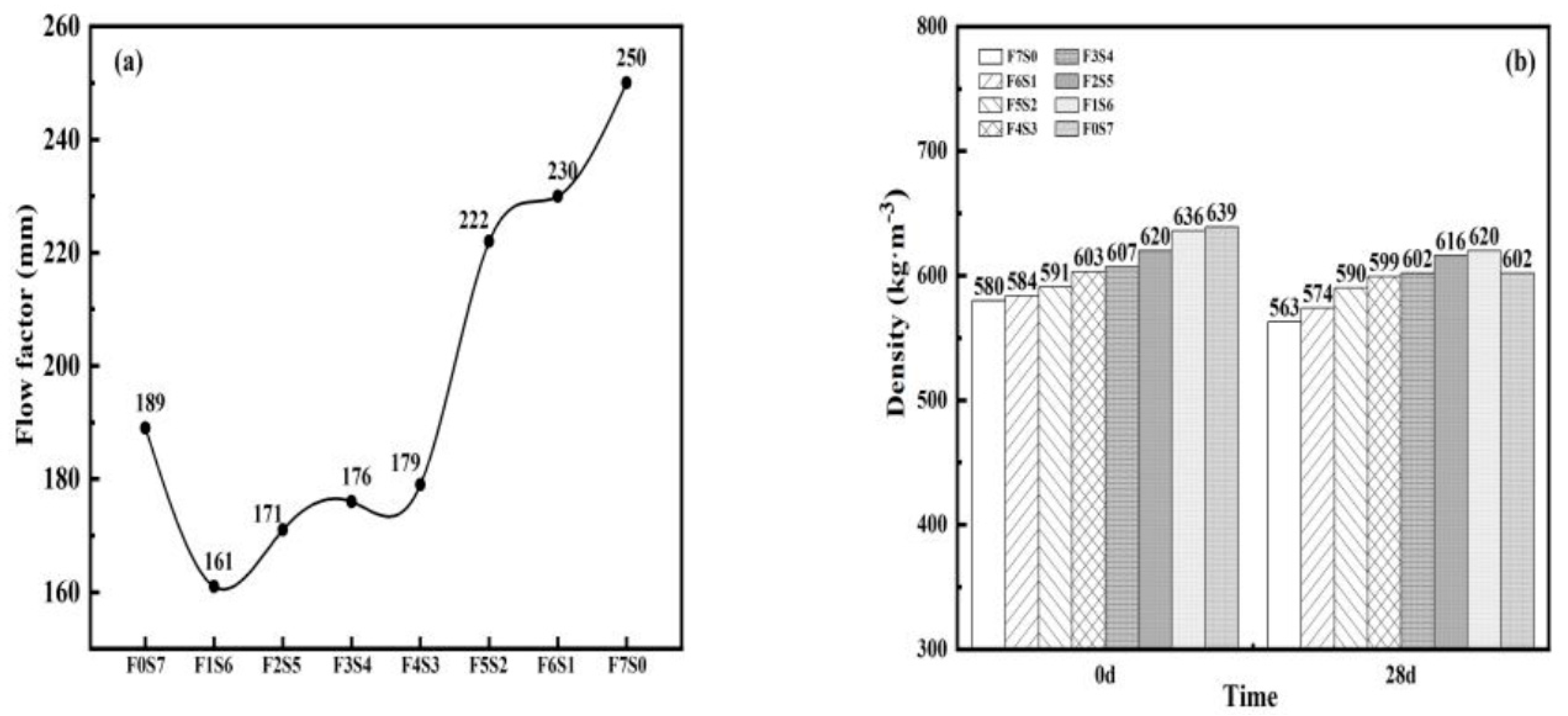
The flowability of LCFLS under the condition of fixed cement dosage and water–binder ratio changed, as shown in Figure 2a. From Figure 2a, it can be seen that when the amount of FA in the LCFLS was greater than 10%, its flowability increased with the increased FA. Many studies have also shown that FA particles with their spherical morphology have a tumbling effect in the slurry, and can improve the flowability of the slurry [26]. In contrast, GBFS is mostly angular, irregularly polyhedral, and incompatible [27]. As the amount of FA in the system increased, the number of particles with smooth and spherical surfaces increased, improving the dispersion of the foam and expanding the flowability. When the amount of FA exceeded 50%, the excessive flowability made it difficult to mix the foam with the slurry, resulting in delamination of the foam. The flowability of the specimen (F0S7) with 70% of GBFS reached 189 mm instead, which was because, under this condition, the foam would break and merge when the GBFS was mixed with the foam; then, the broken foam became water, which increased the flowability of the slurry [28]. Therefore, a high content of GBFS increases the chance of foam rupture when mixing, which increases the flowability of the LCFLS to a certain extent.
Figure 2b shows a histogram of the wet and quasi-dry densities of the LCFLS. It can be seen from Figure 2b that the wet density of the LCFLS increased with the amount of GBFS at a constant cement dosage. This is because the density of GBFS is greater than that of FA; therefore, the more GBFS used, the greater the theoretical design density of the LCFLS. The difference between the quasi-dry density and the wet density reflects the homogeneity of the LCFLS. The low-mass loss of samples F3S4 and F4S3 indicated that the LCFLS prepared under these mixed designs had good homogeneity, and that most of the pores formed after hardening were not connected to the outside and had less water loss.

3.2. Rheological Properties of LCFLS

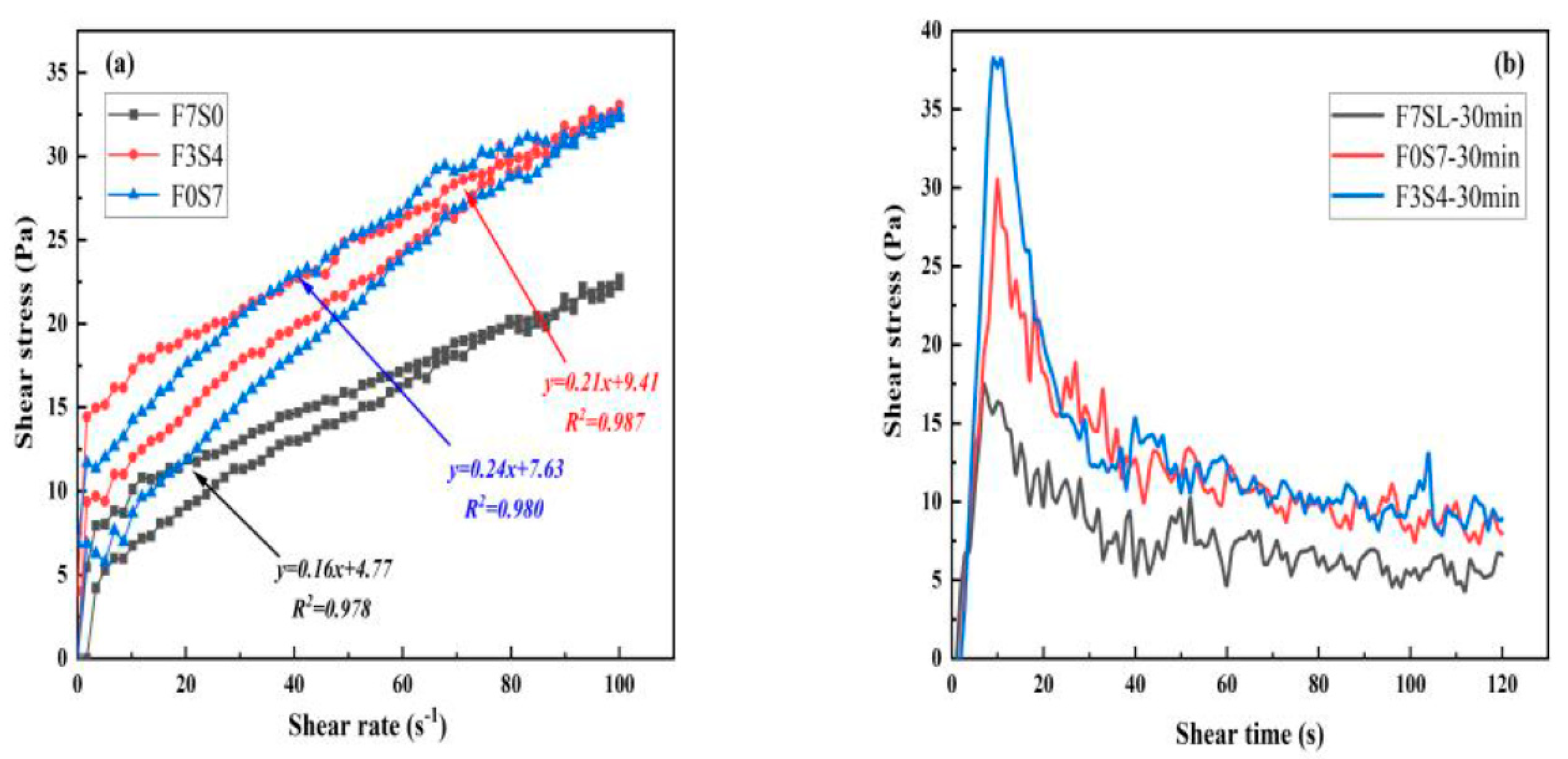
Figure 3a shows the rheological curve of the fresh slurry of the LCFLS after mixing. As there was a large amount of foam inside the mixed slurry, the acceleration and deceleration turns did not coincide during the test, due to the rupture of some foam. The acceleration phase of the mixed slurry was more consistent with the state of the mixed slurry at rest, so the acceleration phase was chosen to characterize the rheological properties of the LCFLS. The relationship between shear stress and shear rate was obtained by fitting the acceleration phase curve using the Bingham model τ = τ 0 + μ γ . It can be seen that, on the one hand, the fitted curves for each group had R2 values around 0.98, indicating that the prepared LCFLS had good rheological properties. On the other hand, the dynamic yield stress τ d of sample F3S4 at 9.41 Pa was greater than that of sample F0S7 at 7.63 Pa and sample F7S0 at 4.77 Pa, indicating that the yield stress of sample F3S4 in the freshly mixed slurry was high; the solid particles in the mixed slurry did not sink easily. In contrast, the foam did not float effortlessly, and the overall homogeneity was good.
To simulate the state of the LCFLS after casting, the LCFLS slurry was left to stand for 30 min, and its static yield stress was measured. Figure 3b shows the static yield stress curve of the 30 min standing slurry. From Figure 3b, it could be found that after 30 min of standing, the yield stress of each group of samples increased in comparison to that of the freshly mixed slurry. Specifically, the static yield stress of sample F0S7 was 5.51 Pa; sample F3S4 was 10.32 Pa; and sample F0S7 was 9.97 Pa. This indicated that after 30 min, the internal hydration of the LCFLS increased the yield stress of the slurry. In addition, sample F0S7 increased more, indicating that the GBFS was more active and more accessible to excite than the FA.

3.3. Compressive Strength of LCFLS

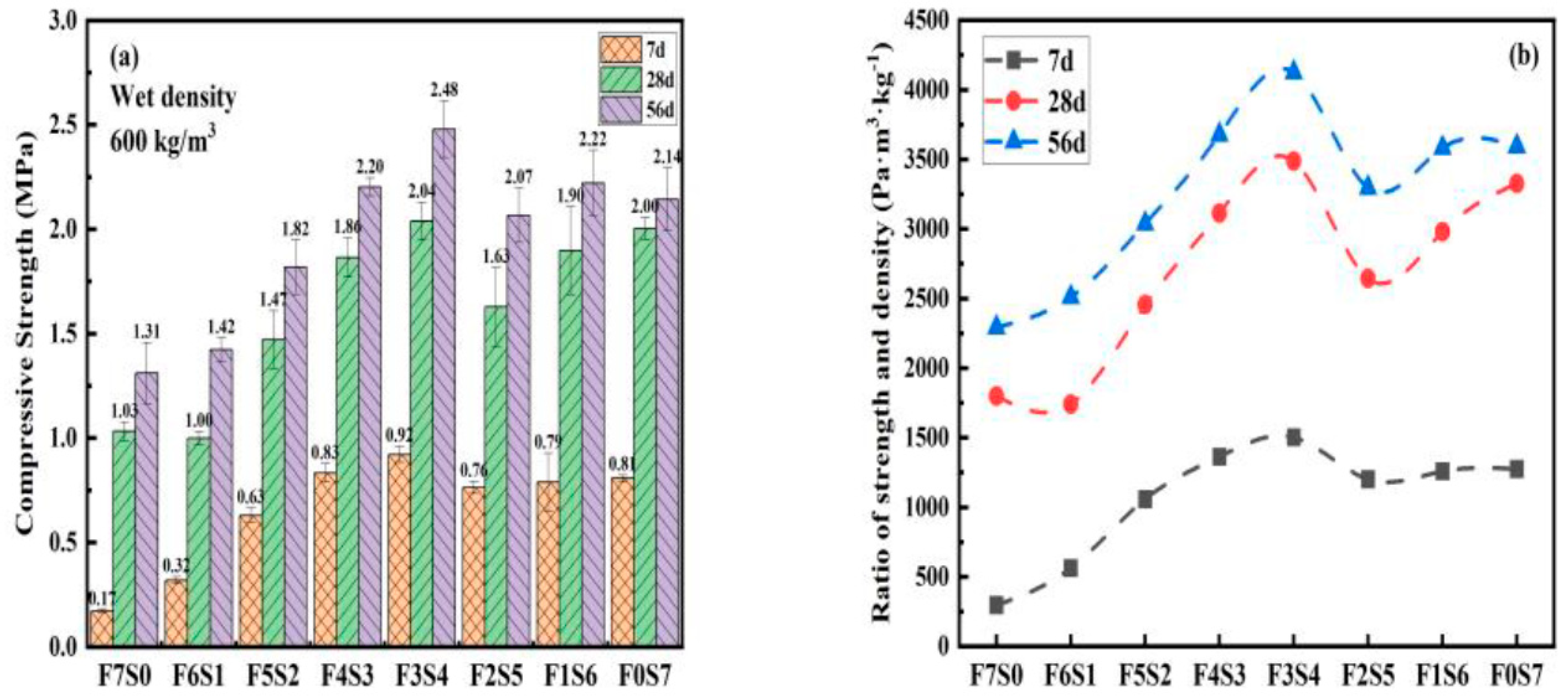
Figure 4a shows the changes in the mechanical properties of the LCFLS at 7 d, 28 d, and 56 d. From Figure 4a, it can be seen that the compressive strength of the LCFLS at 7 d, 28 d, and 56 d increased significantly with an increase in the amount of GBFS, and the compressive strength reached a maximum when the amount of GBFS reached 40%. Conversely, when the amount of GBFS continued to increase, the compressive strength of the LCFLS decreased. Combined with the analysis in Section 3.1 and Section 3.2, sample F3S4 had the best homogeneity during the preparation process, which indicated that the homogeneity of the mixed slurry mainly controlled the mechanical properties of the LCFLS during the overall preparation process.
To further investigate the relationship between the strength and the composition of the cementitious materials of the LCFLS, the ratio of compressive strength and density at different ages was determined, as shown in Figure 4b. It could be seen that the compressive density ratio (ratio of compressive strength and density) of sample F3S4 was more significant than that of the other samples, and the growth rate of the compressive density ratio was also higher than those of the others. This was consistent with the above conclusion that the homogeneity of the mixed slurry mainly controls the mechanical properties of the LCFLS. Furthermore, a comparison of the compressive density ratios of samples F7S0 and F0S7 showed that the contribution of the GBFS to the strength of the LCFLS was more outstanding than that of the FA, which led to the conclusion that the type of cementitious material also affected the mechanical properties of the LCFLS.

3.4. Hydrate Analysis of LCFLS

3.4.1. XRD

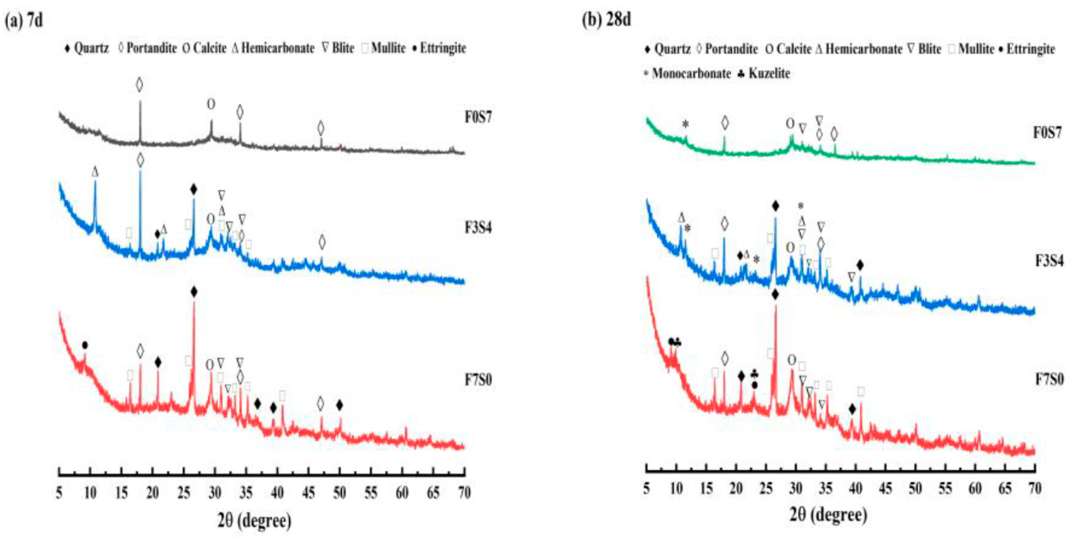
XRD analysis can reflect the type of hydration products of the samples, which can help reveal the LCFLS system’s hydration mechanism. Samples of F0S7, F3S4, and F7S0 with hydration ages of 7 d and 28 d were selected for XRD analysis, as shown in Figure 5. It was clear from Figure 5 that the peaks of the Ca(OH)2 phase (portlandite, PDF#44-1481) was the main hydration product of the LCFLS [29], while samples F3S4 and F7S0 had the quartz phase (quartz, PDF#46-1045) and the mullite phase (mullite, PDF#833-1881) introduced by FA. F7S0 was hydrated to form the AFt phase (ettringite, PDF#41-1451) and the SO4-AFm phase (kuzelite, PDF#50-1607). F0S7 formed mostly amorphous hydrotalcite-like structures and C-S(A)-H gels; therefore, its XRD pattern had the fewest peaks of all. F3S4 produced calcium sulphoaluminate Ms (monosulfate, PDF#83-1829), which is highly susceptible to carbonization into calcium carboaluminate Mc (monocarbonate, PDF#41-0727), and Hc (hemicarbonate, PDF#36-0129). Similarly, the Ca(OH)2 produced by the hydration of the cement was also partially carbonized and converted into a calcium carbonate phase (calcite, PDF#05-0586). As the age of hydration increased, the intensity of the Ca(OH)2 peak decreased, indicating that generated Ca(OH)2 was the continuous reaction with GBFS and FA consumed.

3.4.2. TG–DTG

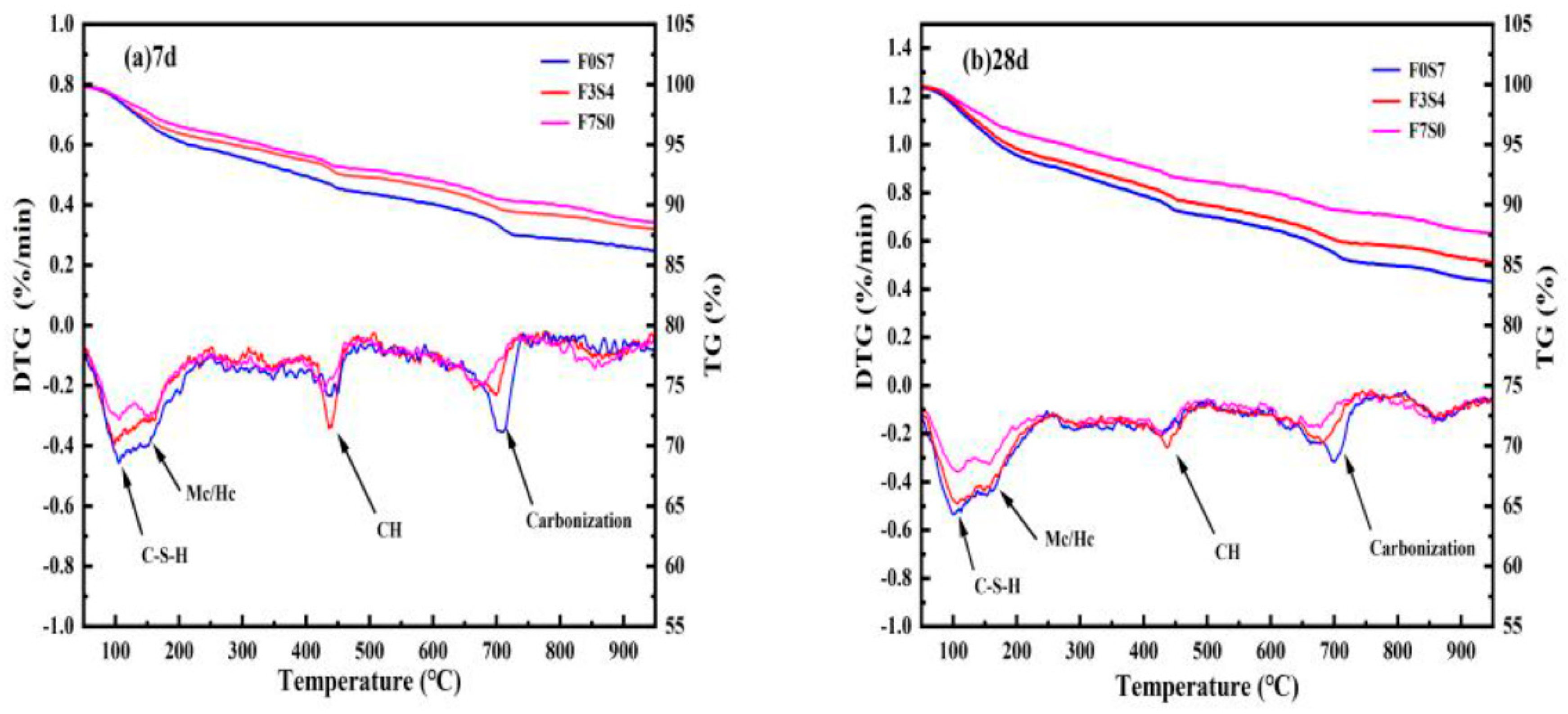
A comprehensive thermal analysis can quantify the mass change of hydration products. This analysis reflected the cement’s hydration and GBFS and FA excitation degrees. F0S7, F3S4, and F7S0 hydration samples aged 7 d and 28 d were selected for TG–DTG analysis. The results are shown in Figure 6. At 50–200 °C, all groups showed broad weight loss peaks. It was removed for the C-S-H gel, where F7S0 corresponded to the less crystalline SO4-AFM phase. F3S4 and F0S7 corresponded to the Mc and Hc phases [30]. The weight loss at 400–500 °C was caused by CH decomposition, while the decomposition of the CH carbonation product CaCO3 occurred at 650–750 °C. The weight losses of three samples are shown in Table 5. The weight loss of specimens increased in different temperatures as the content of FA replaced by GBFS decreased, indicating that the GBFS’s hydration activity was superior to that of FA. From the CH content calculated from Equation (1), it was found that the CH content at 28 d in all three samples was higher than that for 7 d, indicating that under the condition of a larger water–binder ratio, the volcanic ash reaction of FA and GBFS promoted the hydration degree of cement. Moreover, the promotion effect of GBFS on cement hydration was better than that of FA. However, the filling effect of GBFS was not as good as FA’s, and the LCFLSs were porous materials. Therefore, the hydration products in samples containing GBFS are more likely to be carbonized. In addition, comparing the weight loss of samples at 7 d and 28 d, it was found that the increase in C-S-H gel in sample F3S4 was significantly higher than that in the other two samples. This suggests that the compounding the right proportion of GBFS and FA excited and hydrated each other, which elevated the system’s C-S-H gel content.

3.4.3. SEM

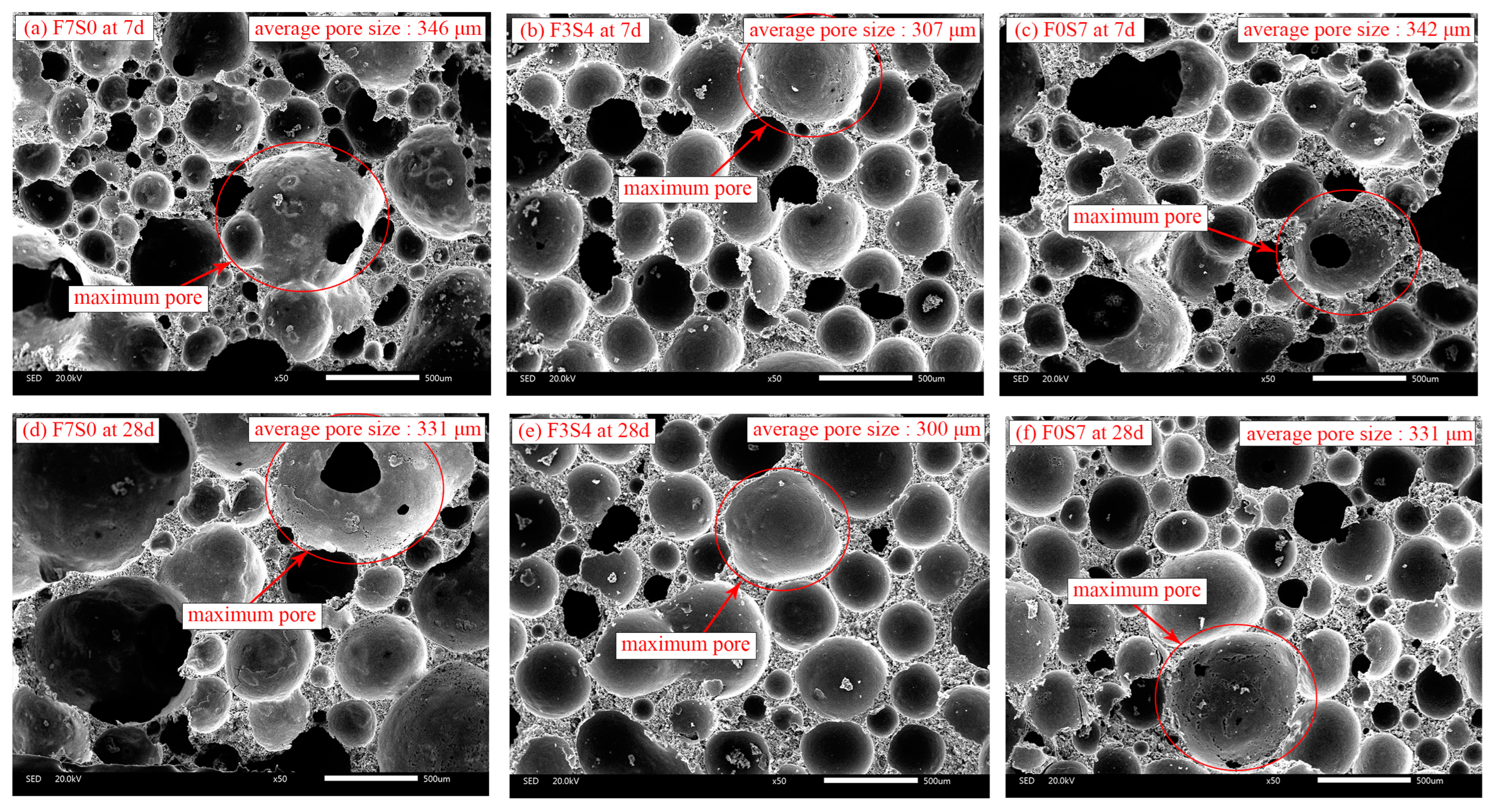
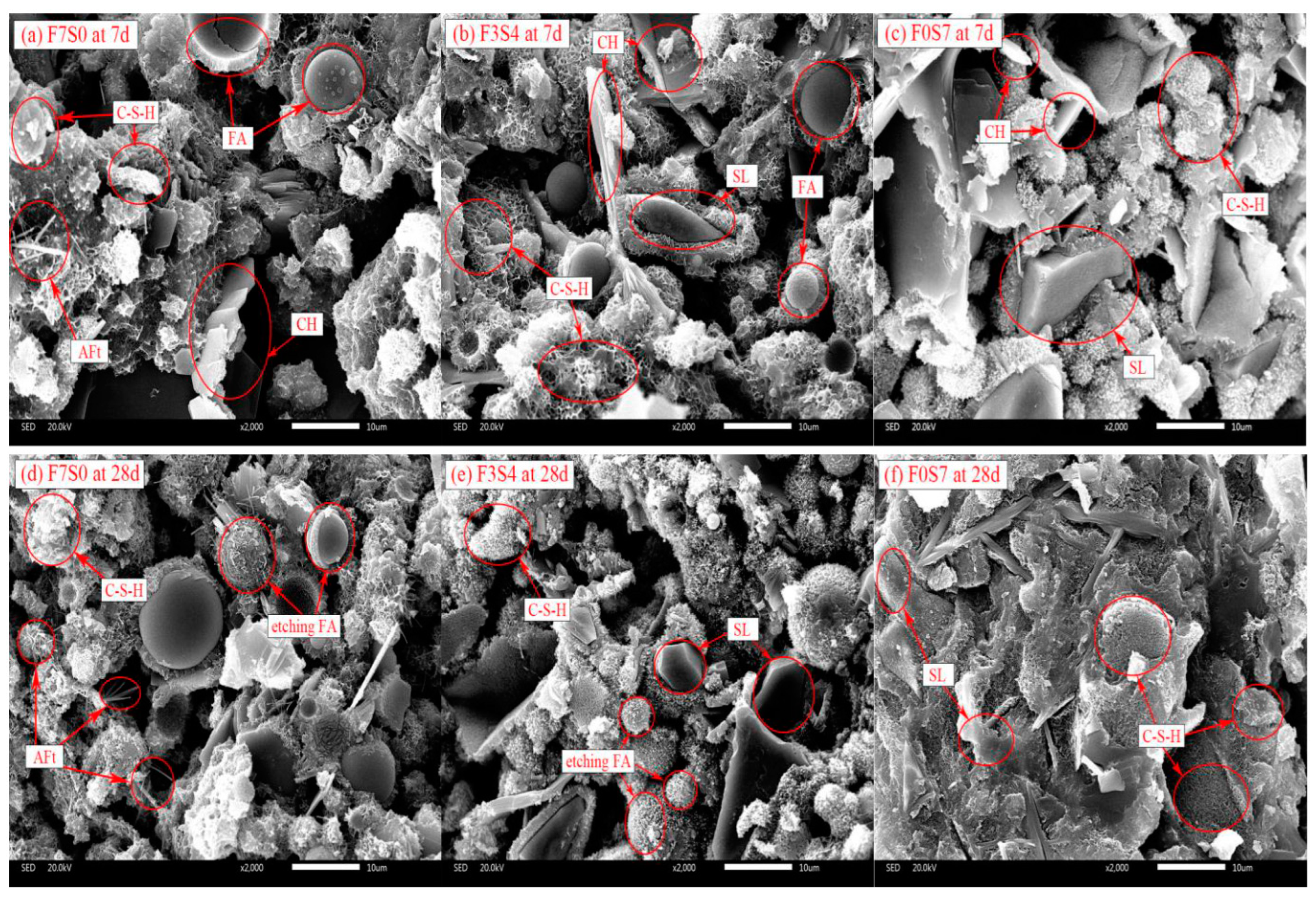
Samples with hydration ages of 7 d and 28 d were selected for SEM analysis for F0S7, F3S4, and F7S0. The pore structures and pore distributions of three samples at 7 d and 28 d at 50 times are shown in Figure 7a–f, and the morphology of the hydration products of the three samples at 2000 times are shown in Figure 8a–f. A Nano Measurer software was used to count the pores’ sizes in the obtained pictures, and the pore size distributions and average pore size results were obtained, as shown in Table 6 and Figure 9. It could be seen that the average pore size of sample F3S4 was 303 μm, which was smaller than that of the other two samples. The pore sizes of samples F0S7 and F7S0 (7 d and 28 d) were not uniform, with larger pores and a few connecting pores. However, the pore sizes and distribution of sample F3S4 (7 d and 28 d) were better than those of samples F0S7 and F7S0 at the corresponding ages. The pores were all spherical, with smooth inner walls and independent pores, with few connections. A Gaussian function was used to fit the pore diameter distribution to obtain the pore’s mean value and standard deviation. It could be seen that the mean value of sample F3S4 was the minimum difference between the average pores, and was 24 μm. In addition, the standard deviation obtained by sample F3S4 was the smallest, indicating that its pore diameter distribution was more uniform.
As shown in Figure 8, the microstructure of hardened LCFLS consisted of unhydrated spherical FA and polygonal GBFS, as well as hydration products. These hydration products were mainly flocculent C-S-H gels and hexagonal flakes of Ca(OH)2. Aft was only present in sample F7S0, mainly because the incorporation of GBFS increased the Al content and reduced the system’s alkalinity, inhibiting the formation of Aft [31]. Samples F3S4 and F7S0 at 28 d had some FA with surfaces that had been “etched”. The surface of FA in sample F3S4 was more severely “etched” than that in sample F7S0. On the one hand, the incorporation of GBFS further promoted the volcanic ash reaction of the FA. On the other hand, sample F3S4 had better homogeneity, and the FA was more uniformly dispersed, which made the volcanic ash reaction of the FA more complete.

3.5. Stability of LCFLS

The preparation of LCFLS can be divided into two main processes: (1) mixing of the slurry and foam; (2) hardening by casting into the mold. In order to prepare a stable LCFLS, it is necessary to ensure the homogeneity of the freshly mixed slurry and the non-settling of the mixed slurry during hardening.

3.5.1. Analysis of the Homogeneity of the Freshly Mixed Slurry

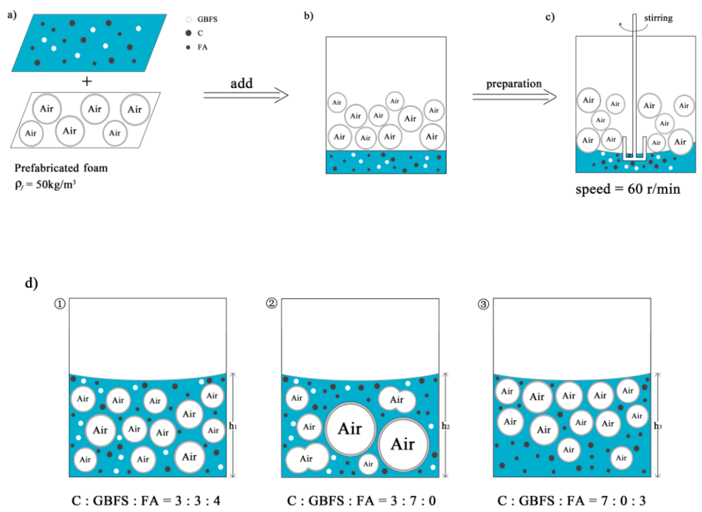
Figure 10 shows a schematic diagram of the mixing process of LCFLS. In particular, Figure 10a–c show the whole process of mixing, and Figure 10d shows the situation of different samples with mixing completed. According to the results in Section 3.1, Section 3.2 and Section 3.4, it is clear that sample F3S4 had a suitable flowability and wet density; the hardened slurry also had more uniform pores, which results in a more uniform freshly mixed slurry, as shown in Figure 10d ①. Sample F0S7 had excessive GBFS content in the initial slurry, and there was a partial rupture and merging of foam, which resulted in more oversized foam that made the wet density out of control. The pore size of the hardened slurry was also significant, as shown in Figure 10d ②. The excessive FA content in the initial slurry of sample F7S0 caused low viscosity, making the foam and slurry easily become delaminated, and the wet density was small. The foam within the foam layer also merged, making the hardened slurry’s pore size partially large, as shown in Figure 10d ③.
Therefore, in mixing the LCFLS slurry, a more suitable flowability of 170–180 mm can be controlled to obtain a more homogeneous freshly mixed slurry.

3.5.2. Analysis of the Collapse Mechanism during Hardening

During the hardening process of the LCFLS, the overall initial and final setting times of the slurry mix were long, due to the designed water–binder ratio of 0.65, and the cement only accounted for 30% of the cementitious material. Therefore, these setting times were much longer than the stabilization time of the foam. Hence, it was necessary to carry out a force analysis of the foam in the hardening system, in order to ensure that no relative flow of the mixture occurred.
Figure 11 shows the force analysis of a single foam in a hardening homogeneous slurry. In addition, the foam density was 50 kg/m3, which was far smaller than the mixed slurry’s density. Hence, in this situation, the gravity of the foam was ignored. The foam was subjected to the buoyancy force Fb of the slurry and the resistance of the slurry against it. It was assumed that both the slurry and the foam remained stationary, and the force equation could be formulated as follows:
F b = 4 3 π R f 3 ρ g
f r = 4 π R f 2 τ s
F b f r
τ s ρ g R f 3
where R f is the radius of the foam, ρ is the density of the slurry, g is the acceleration of gravity, and is the static yield stress of the slurry. For sample F3S4, the radius of the foam R f ≈ 152 μm, the density of the slurry ρ ≈ 1613 kg/m3, and the substitution calculation yielded τ s ≥ 0.80 Pa. This meant that as long as the static yield stress of the slurry was greater than 0.80 Pa, the relative flow and settlement of the hardening mixture would not occur. Similarly, for sample F7S0, its τ s ≥ 0.85 Pa, and for sample F0S7, τ s ≥ 0.91 Pa. According to the results measured in Section 3.2, the static yield stress of all of the samples was greater than 5 Pa after 30 min of standing. Thus, it can be concluded that the LCFLS designed in this study has good stability. Collapsing did not occur during the hardening process, due to the long setting time of the cementitious material.

4. Conclusions

(1) FA had a ball effect in the slurry, which reduced the chance of foam rupture, and improved the flowability of the slurry. GBFS had higher hydrated activity, and provided better mechanical properties. The flowability of LCFLS with better homogeneity was about 170–180 mm, and the wet density was not much different from the quasi-dry density, basically within 10 kg/m3.
(2) The rheological properties of the freshly mixed slurry conformed to the Bingham model. The higher the dynamic yield stress, the more uniformly the solid particles and foam in the mixed slurry were dispersed, and the better the overall homogeneity. After 30 min of standing, the static yield stress of the LCFLS slurry already exceeded 5 Pa, at which point the foam did not collapse due to the relative movement of buoyancy.
(3) The LCFLS prepared with 30% PC, 30% FA, and 40% GBFS showed good homogeneity of the mixed slurry; the pores had a spherical shape, with smooth inner walls and an average pore size of around 300 μm. The main hydration products were C-S-H gel and CH, with small amounts of carbonation products CaCO3, Hc, and Mc. The compressive strengths at 7 d and 28 d reached 0.92 MPa and 2.04 MPa, respectively.

Author Contributions

Conceptualization, H.W.; methodology, C.S.; validation, C.S. and H.W.; investigation, H.L.; resources, J.L.; data curation, Q.H. and J.X.; writing—original draft preparation, C.S.; writing—review and editing, H.W.; visualization, P.L.; supervision, H.W.; project administration, H.L.; funding acquisition, H.L., J.L. and P.L. All authors have read and agreed to the published version of the manuscript.

Funding

This research was funded by the China Construction Group Limited Project: “Integrated Construction Technology Research on Soft Ground Track Grade High Speed Road”, grant number CSCEC-2019-Z-29.

Data Availability Statement

The data that support the findings of this study are available from the corresponding author upon reasonable request.

Conflicts of Interest

The authors declare no conflict of interest.

References

  1. Shah, S.N.; Yap, S.P. Lightweight foamed concrete as a promising avenue for incorporating waste materials: A review. Resour. Conserv. Recycl. 2021, 164, 105103. [Google Scholar] [CrossRef]
  2. Narayanan, N.; Ramamurthy, K. Structure and properties of aerated concrete: A review. Cem. Concr. Compos. 2000, 22, 321–329. [Google Scholar] [CrossRef]
  3. Amran, Y.M.; Farzadnia, N. Properties and applications of foamed concrete: A review. Constr. Build. Mater. 2015, 101, 990–1005. [Google Scholar] [CrossRef]
  4. Youssef, M.B.; Neji, J. Upscaling the elastic stiffness of foam concrete as a three-phase composite material. Cem. Concr. Res. 2018, 110, 13–23. [Google Scholar] [CrossRef] [Green Version]
  5. Ortiz, O.; Sonnemann, G. Sustainability in the construction industry: A review of recent developments based on LCA. Constr. Build Mater. 2009, 23, 28–39. [Google Scholar] [CrossRef]
  6. Huang, J.J.; Su, Q. Experimental study on use of lightweight foam concrete as subgrade bed filler of ballastless track. Constr. Build Mater. 2017, 149, 911–920. [Google Scholar] [CrossRef]
  7. Watabe, Y.; Noguchi, T. Site-investigation and geotechnical design of D-runway construction in Tokyo haneda airport. Soils Found. 2011, 51, 1003–1018. [Google Scholar] [CrossRef] [Green Version]
  8. Kikuchi, Y.; Mizutani, T.A. The effect of air foam inclusion on the permeability and absorption properties of light weight soil. Soils Found. 2011, 51, 151–165. [Google Scholar] [CrossRef] [Green Version]
  9. Kearsley, E.P.; Wainwright, P.J. The effect of high fly ash content on the compressive strength of foamed concrete. Cem. Concr. Res. 2001, 31, 105–112. [Google Scholar] [CrossRef]
  10. Liu, H.; Wang, H. Preparation and Performance Study of Large Volume Foamed Lightweight Soil for an Intelligent Networked Vehicle Test Site. Materials 2022, 15, 5382. [Google Scholar] [CrossRef]
  11. Zhang, Z. Geopolymer foam concrete: An emerging material for sustainable construction. Constr. Build. Mater. 2014, 56, 113–127. [Google Scholar] [CrossRef]
  12. Qing, J.G.; Jie, W.Z. The effects of pozzolanic powder on foam concrete pore structure and frost resistance. Constr. Build. Mater. 2019, 208, 135–143. [Google Scholar]
  13. Hang, M.Y.; Ran, Y. Influence of mineral admixtures on properties of foam concrete. Bull. Chin. Ceram. Soc. 2018, 37, 1480–1486. [Google Scholar]
  14. Kearsley, E.P.; Wainwright, P.J. The effect of porosity on the strength of foamed concrete. Cem. Concr. Res. 2002, 32, 233–239. [Google Scholar] [CrossRef]
  15. Jones, M.R.; McCarthy, A. Heat of hydration in foamed concrete: Effect of mix constituents and plastic density. Cem. Concr. Res. 2006, 36, 1032–1041. [Google Scholar] [CrossRef]
  16. Falliano, D.; Ricciardi, G. Experimental investigation on the compressive strength of foamed concrete: Effect of curing conditions, cement type, foaming agent and dry density. Constr. Build. Mater. 2018, 165, 735–749. [Google Scholar] [CrossRef]
  17. Jiang, J.; Yang, Y. Facile preparation and hardened properties of porous geopolymer-supported zeolite based on swelled bentonite. Constr. Build. Mater. 2019, 228, 117040. [Google Scholar] [CrossRef]
  18. Ma, B.; Tan, H. Effect of triisopropanolamine on compressive strength and hydration of cement-fly ash paste. Constr. Build. Mater. 2018, 179, 89–99. [Google Scholar] [CrossRef]
  19. Dhasindrakrishna, K.; Pasupathy, K. Effect of yield stress development on the foam-stability of aerated geopolymer concrete. Cem. Concr. Res. 2020, 138, 106233. [Google Scholar] [CrossRef]
  20. Blandine, F.; Olivier, P. Optimal cement paste yield stress for the production of stable cement foams. Cem. Concr. Res. 2019, 120, 142–151. [Google Scholar]
  21. Hoang, M.T.; Perrot, C. Solid films and transports in cellular foams. J. Appl. Phys. 2012, 112, 054911. [Google Scholar] [CrossRef] [Green Version]
  22. Roussel, N.; Brumaud, C. The origins of thixotropy in fresh cement pastes. Cem. Concr. Res. 2012, 42, 148–157. [Google Scholar] [CrossRef]
  23. China Association for Engineering Construction Standardization. Technical Specification for Cast-In-Situ Foamed Lightweight Soil: CECS 249:2008; China Planning Press: Beijing, China, 2008. [Google Scholar]
  24. Long, L.; Chi-sun, P. Rheology behavior of one-part alkali activated slag/glass powder (AASG) pastes. Constr. Build. Mater. 2020, 258, 120381. [Google Scholar]
  25. State Administration for Market Regulation. Test Methods of Autoclaved Aerated Concrete: GB/T 11969-2020; Standards Press of China: Beijing, China, 2020. [Google Scholar]
  26. Wei, S.; Yi, D. Influence of coarse fly ash on the performance of foam concrete and its application in high-speed railway roadbeds. Constr. Build. Mater. 2018, 170, 153–166. [Google Scholar]
  27. Font, A.; Soriano, L. Salt slag recycled by-products in high insulation alternative environmentally friendly cellular concrete manufacturing. Constr. Build. Mater. 2020, 231, 117114. [Google Scholar] [CrossRef]
  28. Zhao, W.H. Study on the Structural Performances and Construction Technologies of Foamed Concrete Subgrade of High-Speed Railway. Ph.D. Thesis, Southwest Jiaotong University, Chengdu, China, 2018. [Google Scholar]
  29. Panesar, D.K. Cellular concrete properties and the effect of synthetic and protein foaming agents. Constr. Build. Mater. 2013, 44, 575–584. [Google Scholar] [CrossRef]
  30. Li, B. Study on the Mechanism of Hydration and Structural Evolution of Slag Cement Modified with Keggin-Al13. Ph.D. Thesis, Wuhan University of Technology, Wuhan, China, 2020. [Google Scholar]
  31. Weerdt, K.D.; Haha, M.B. Hydration mechanisms of ternary Portland cements containing limestone powder and fly ash. Cem. Concr. Res. 2011, 41, 279–291. [Google Scholar] [CrossRef]
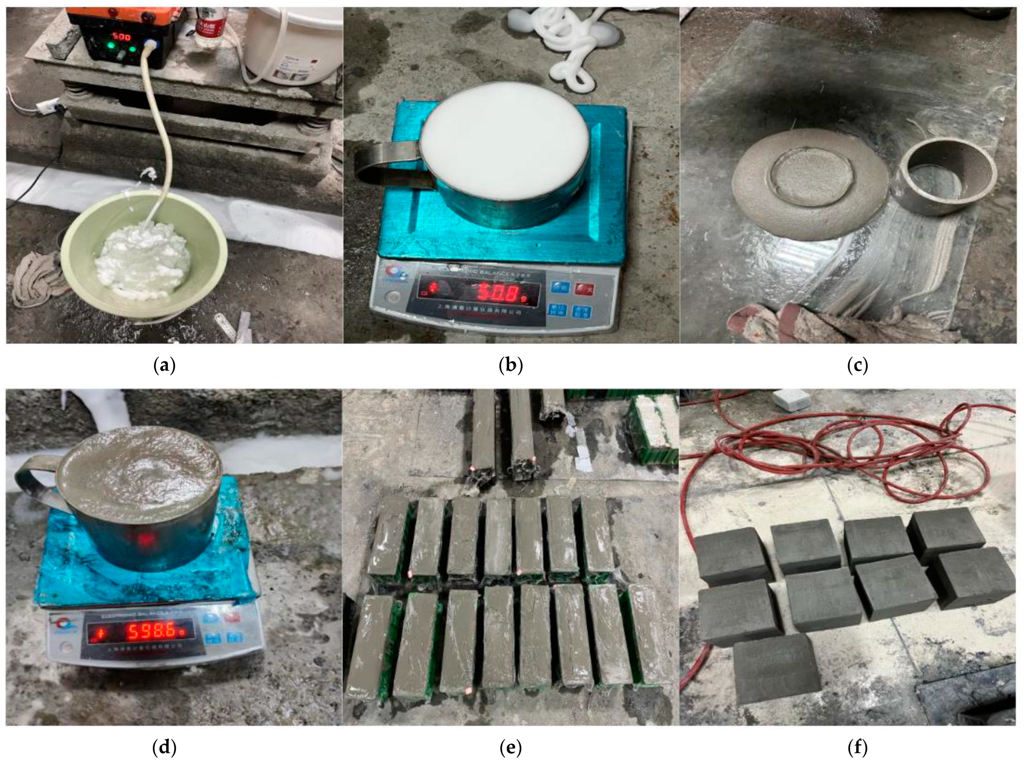
Figure 1. Production process of LCFLS: (a,b) foam preparation; (c,d) measurement of flowability and wet density; (e,f) molding and curing.
Buildings 13 00759 g001
Figure 2. Working performance of the LCFLS: (a) flowability; (b) wet density and quasi-dry density.
Buildings 13 00759 g002
Figure 3. Rheological properties of the LCFLS: (a) dynamic yield stress at 0 min; (b) static yield stress at 30 min.
Buildings 13 00759 g003
Figure 4. Mechanical performance of the LCFLS: (a) compressive strength; (b) ratio of strength and density.
Buildings 13 00759 g004
Figure 5. XRD patterns of the LCFLS: (a) 7 d; (b) 28 d.
Buildings 13 00759 g005
Figure 6. TG–DTG curves of the LCFLS: (a) 7 d; (b) 28 d.
Buildings 13 00759 g006
Figure 7. SEM images of the LCFLS at 50× magnification.
Buildings 13 00759 g007
Figure 8. SEM images of the LCFLS at 2000× magnification.
Buildings 13 00759 g008
Figure 9. Pore size distributions of LCFLS.
Buildings 13 00759 g009
Figure 10. Theoretical mixing process of LCFLS.
Buildings 13 00759 g010
Figure 11. Force analysis of foam in LCFLS.
Buildings 13 00759 g011
Table 1. Physical properties of P·O 42.5 cement.
Density/(kg/m3)Specific Surface Area/(m2/kg)Soundness of Cement/mmSetting Time/minFlexural Strength/MPaCompressive Strength/MPa
InitialFinal3 d28 d3 d28 d
310034021702355.68.728.150.4
Table 2. Chemical compositions of the materials (wt%).
MaterialCaOSiO2Al2O3Fe2O3MgOSO3K2ONa2OTiO2LOI
Cement60.1120.925.763.241.152.860.880.140.314.17
Granulated Blast Furnace Slag39.9231.2314.120.787.342.230.610.720.76−0.29
Fly Ash0.4457.6421.496.521.770.373.420.120.936.85
Table 3. Mix designs of LCFLS (kg/m3).
No.Cementitious Material SystemsWaterFoam
PCGBFSFA
F0S71052450227.532.2
F1S610521035227.532.2
F2S510517570227.532.2
F3S4105140105227.532.2
F4S3105105140227.532.2
F5S210570175227.532.2
F6S110535210227.532.2
F7S01050245227.532.2
Table 4. Performance of LCFLS.
ItemFlowability (mm)Wet Density (kg/m3)7 d Compressive Strength (MPa)28 d Compressive Strength (MPa)
Standard value160–180550–650≥0.5≥1.0
Table 5. Weight losses of the LCFLS system.
Temperature RangeF7S0F3S4F0S7
7 dat 50–200 °C (%)3.33013.85314.5568
at 400–500 °C (%)1.16791.42881.4625
at 650–750 °C (%)1.01391.43301.9891
CH content (%)6.50668.28409.3578
28 dat 50–200 °C (%)3.82005.22885.6405
at 400–500 °C (%)1.27301.60701.6765
at 650–750 °C (%)1.18681.44612.0801
CH content (%)7.22949.038610.3906
Table 6. Pore structure characterization of LCFLS.
Average Diameter (μm)Mean Value (μm) Standard   Deviation   ( σ )
F7S0338298147
F3S4303327101
F0S7336350161
Disclaimer/Publisher’s Note: The statements, opinions and data contained in all publications are solely those of the individual author(s) and contributor(s) and not of MDPI and/or the editor(s). MDPI and/or the editor(s) disclaim responsibility for any injury to people or property resulting from any ideas, methods, instructions or products referred to in the content.