1. Introduction
Tensile structures are made up of tension-carrying components with neither compression nor bending, and they are classified as tensile cable structures and tensile membrane structures [
1]. Tensile cable structures are widely used in modern buildings as well as bridges [
2]. Tensile cable structures used in bridges have a long history of more than two thousand years [
2], but it is widely believed that the first modern tensile cable structure used in a building is the hyperbolic cable net roof of the Dorton Arena [
3] (also called the Raleigh Arena [
4]) built in 1953. Since then, tensile cable structures for buildings have quickly progressed, included various structural forms, and have been applied to many famous buildings. Tensile cable structures are usually composed of tensile steel strands, high-strength tie rods, CFRP cables, or other tensile components [
5]. The tensile cable structures make full use of the high-strength tensile properties of the materials, and these structures exhibit the advantages of being light in weight and having a large span. Currently, the structural forms of tensile cable structures include cable dome structures [
6], space cable-truss structures [
7], wheel-spoke cable structures [
8], single-layer hyperbolic cable net structures [
9], suspen-dome structures [
10], etc.
In recent years, tensile cable structures with loop cables have been studied. Loop cables, which generate radial elements, are commonly used in gymnasiums and football stadiums to achieve a large-span structure [
11]. Despite its advantages, current studies find that loop cables are key components of the structure [
12], and they are subjected to high tensions [
13]. The failure of a segment of a loop cable results in the slacking of the entire loop cable, and the radial components also fail due to the generated slack; moreover, it could cause a progressive collapse of the roof structure. The loop cables bear high tensions due to the adverse angle relationship between the loop cable and the radial component. The loop cables use a large amount of material because of high tensions. With the aim to make improvements, loop-free cable structures have been proposed. Xue et al. [
14] summarized four forms, including the annular crossed cable-truss structure [
15], loop-free single-layer hyperbolic cable net structure (LSHCS) [
16], loop-free suspen-dome structure [
17], and loop-free cable-supported shell with a large central opening [
14]. The loop-free cable structures overcome the loop cable’s disadvantages with respect to its key elements and high tensions, and they provide alternative schemes for tensile cable structures with loop cables.
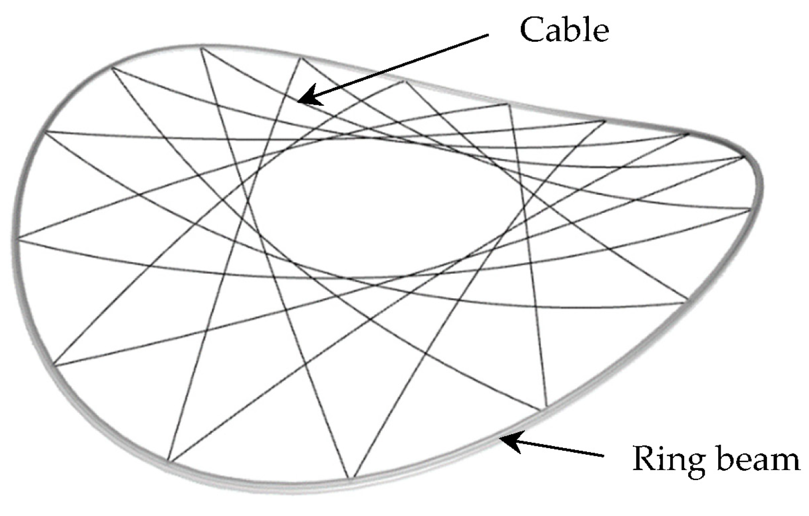
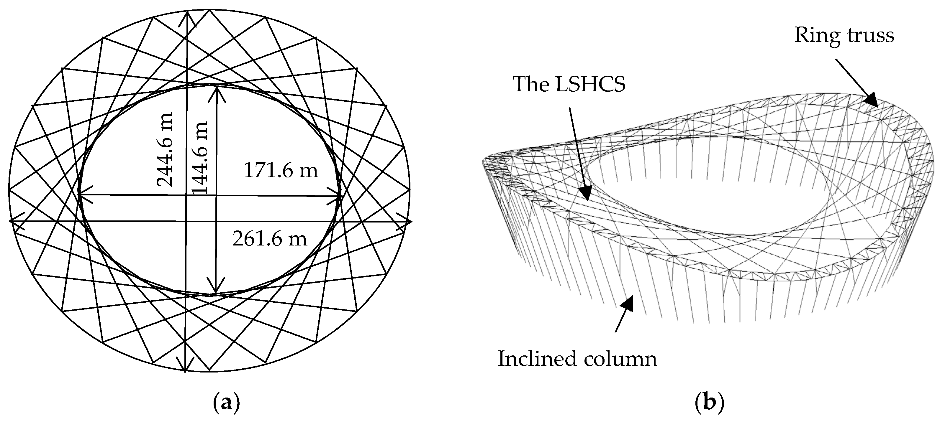
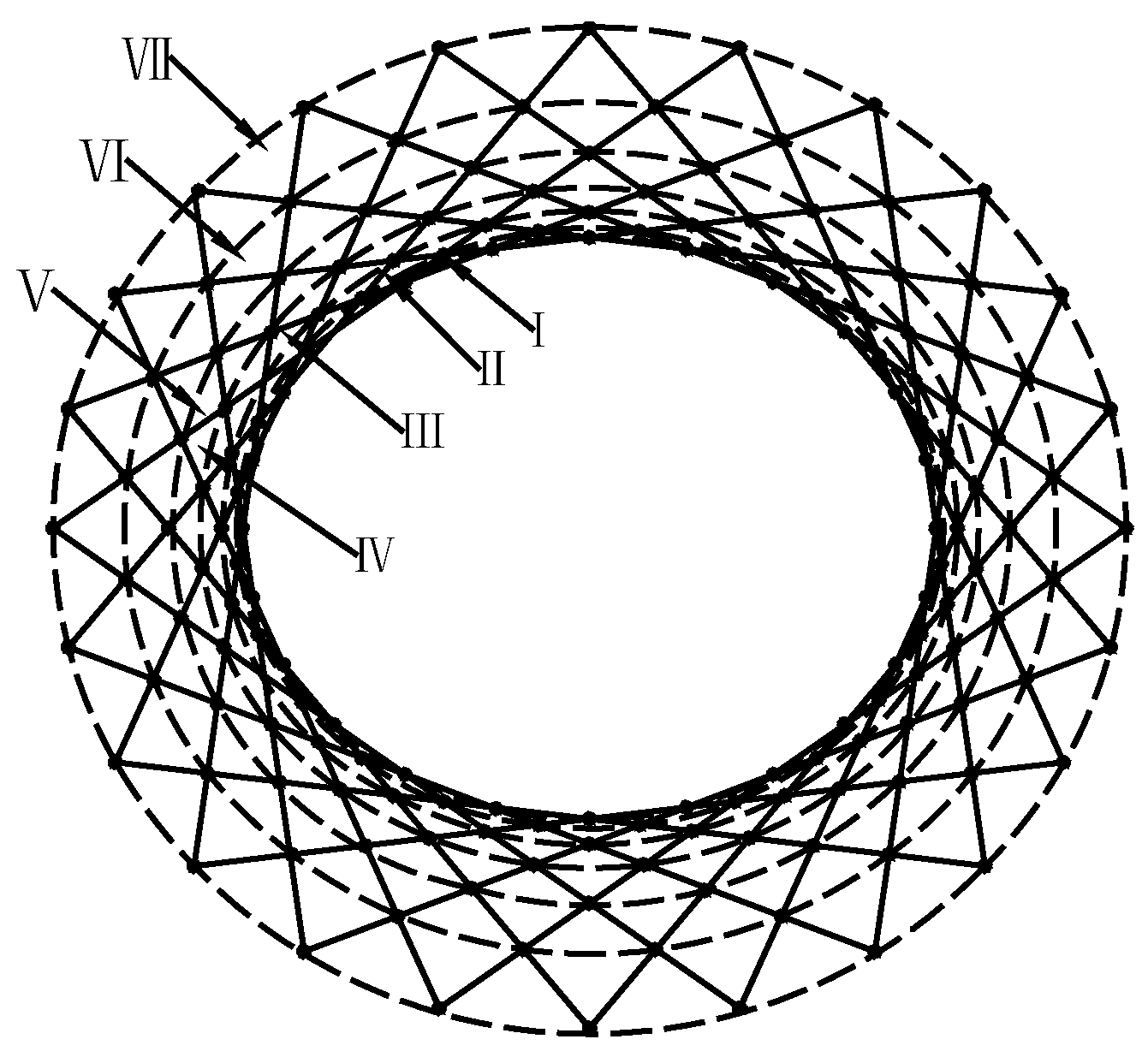
Among current loop-free cable structures, the LSHCS is composed of a loop-free hyperbolic cable net and a compression ring beam to form a self-balancing system (
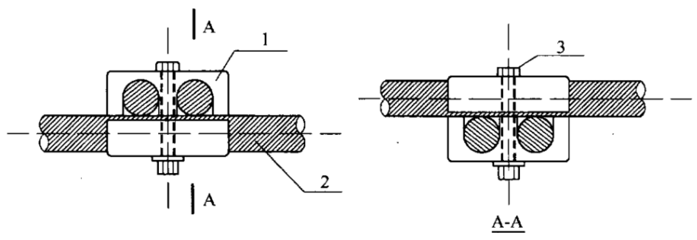
Figure 1). The LSHCS discards loop cables by arranging the cables along the chords of the ring beam. Cables are fixed to the ring beam, and they do not break at intersections of the cable net. Cables are integrated by cable clamps at the crossing points to prevent cable sliding. With this method, cables are relatively independent so the damage to the roof structure could be proportionate if some cables are ruptured [
18]. The cables are straight on the plane projection and hyperbolically curved in the vertical direction. The force-transmitting paths in the LSHCS are much more direct than those of tensile cable structures with loop cables. As a result, tensions of the LSHCS are likely to be reduced. The mechanical properties and design methods of the LSHCS have been studied. Due to the progress, the LSHCS has been considered in engineering applications [
13,
18]. Xue et al. [
19] studied the effect of cable rupture on the structure, verified the progressive collapse resistance, and analyzed the static performance of the LSHCS. Liu et al. [
18] studied the cable arrangements and form-finding method on the LSHCS. It was found that the LSHCS can ensure structural stiffness and overall stability, significantly reduce the amount of material used, and reduce the difficulty of the construction. In addition, the tensions of different cables are much more uniform than the structure with loop cables. However, it can be observed in
Figure 1 that intersections of the LSHCS become denser from the outside to the inside. Since cable clamps are set at intersections, cable clamps near the inside are quite redundant, which could cause unnecessary costs and difficulties during construction. Hence, redundant cable clamps should be properly deleted to achieve a better LSHCS.
In order to determine reasonable cable clamp deletion schemes, the influence of cable clamp deletion on the static behavior and dynamic characteristics of the LSHCS is studied in this paper. Firstly, a large-span LSHCS at the background of a stadium is designed according to the requirements of relevant specifications. Then, twenty-one cable clamp deletion schemes of five levels are considered. The static behavior of all schemes, including adverse displacements under the serviceability limit state and adverse cable tensions under the ultimate limit state, is analyzed with ANSYS software. The analysis of dynamic characteristics including mode shapes and self-vibration frequencies of all schemes is conducted with Midas/Gen software. In the end, based on the comparison between the original structure and each cable clamp deletion scheme, acceptable and reasonable cable clamp schemes are discussed, and advice for cable clamp deletion is provided.
3. Results
3.1. Deleting One Virtual Ring
Table 3 shows the results of SE0 and the schemes of deleting one virtual ring. It is shown that SE1/4 exhibited the smallest increase in
DP compared with SE0, with a growth of 36.48%, followed by an SE1/1 of 42.70%. The largest growth in
DP is 64.32% in SE1/3. This indicates that when deleting cable clamps on one virtual ring, deleting ring V causes the smallest effect on displacements, and deleting ring II causes the second smallest effect. It is shown that SE1/1 has the smallest growth in
MT by 6.09%, and SE1/4 causes growth by up to 13.14%. This indicates that deleting ring II has the smallest effect on
MT, and SE1/4 causes the worst effect.
Table 3 also shows that all schemes induce an increase in
T, indicating that the overall structural stiffness becomes weaker. SE1/2 has the smallest growth in
T by 11.18%, while SE1/4 causes the worst effect by 28.40%.
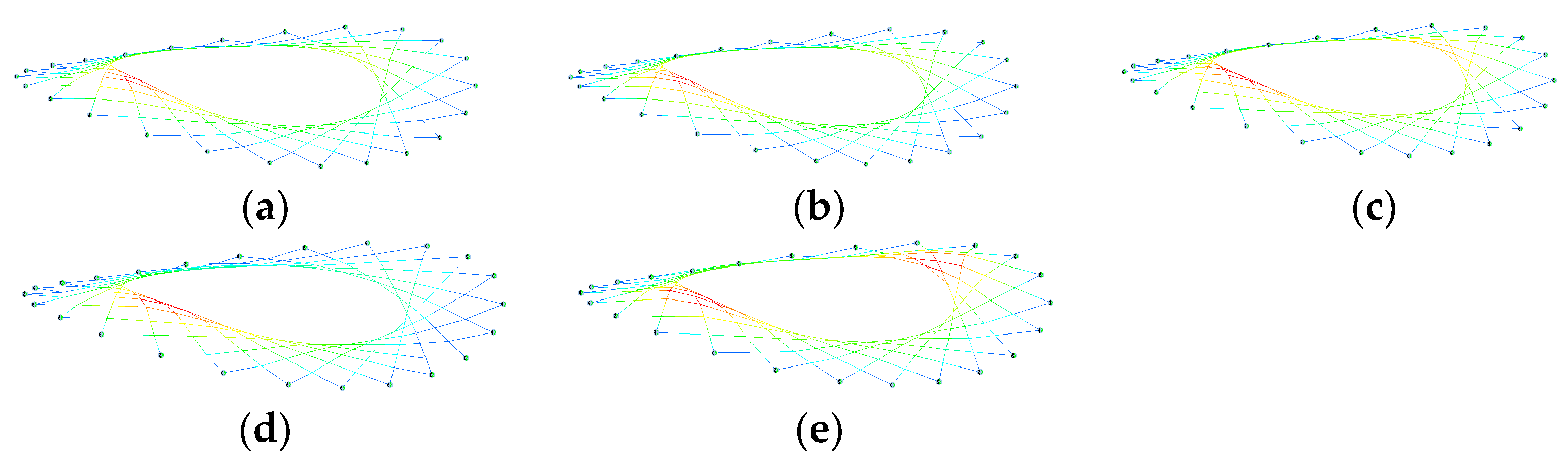
Figure 8 shows that the mode shapes of schemes comprise the overall motion of the cable net, and abnormal motion on the local part does not happen. However, a slight difference from SE0 is that the modes of SE1/1, SE1/2, SE1/3, and SE1/4 comprise antisymmetric motions.
From the analysis above, it was found that displacements are the most sensitive to deleting cable clamps, the natural vibration period comes in second, and the tension is not sensitive. The reason is that the initial structural stiffness changes the most. However, since schemes causing the smallest or the worst effect on PD, MT, and T are different, identifying the best scheme or the worst scheme directly is difficult. SE1/1 causes the least amount of growth in MT, the growth in DP comes in second, and the growth in T comes in third. SE1/1 in which the virtual ring II is involved is selected as the best scheme among the deletion of one virtual ring, while the relative outer virtual ring caused the worse effect. In addition, this conclusion verifies the possibility of removing redundant cable clamps in the densest part of the LSHCS.
3.2. Deleting Two Virtual Rings
Table 4 shows the results of deleting two virtual rings. It is shown that SE2/1 has the smallest increase in
DP compared with SE0, with a growth of 56.82%, and the largest growth in
DP is 124.68% in SE2/9. This indicates that when deleting cable clamps on two virtual rings, deleting the first two rings near the inside boundary of the LSHCS causes the smallest effect on displacements. It is shown that SE2/1 has the smallest growth in
MT by 5.11%, and SE2/10 causes growth by up to 22.71%. This indicates that deleting the first two rings near the inside boundary has the smallest effect on
MT, and deleting the two rings near the outside boundary causes the worst effect.
Table 4 also shows that SE2/1 has the smallest growth in
T by 11.17%, while SE2/10 causes the worst effect by 27.45%.
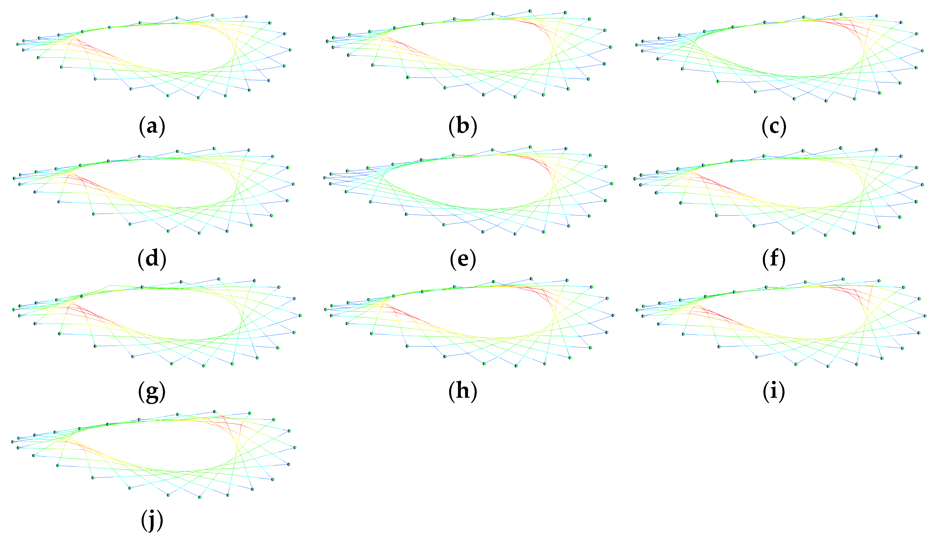
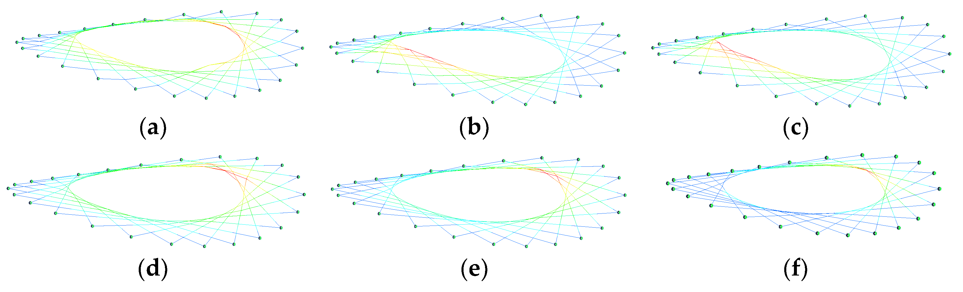
Figure 9 shows that the mode shapes of schemes comprise the overall motion of the cable net, and abnormal motion on the local part does not happen. A slight difference from SE0 is that the modes of some schemes comprise antisymmetric motions.
From the analysis above, similar steps with respect to deleting one virtual ring result in displacements that are the most sensitive to deleting cable clamps; the natural vibration period comes in second, and the tension is not sensitive. Since the scheme causing the smallest or the worst effect on PD, MT, and T is the same, it is easy to identify the best scheme: SE2/1. It is concluded that when deleting cable clamps on two virtual rings, deleting the first two rings near the inside boundary of the LSHCS causes the smallest effect.
3.3. Deleting Three Virtual Rings
Table 5 shows the results of the schemes that delete three virtual rings. It is shown that all schemes induce an increase in
DP, and SE3/1 has the smallest increase in
DP compared with SE0, with a growth of 88.13%. In contrast, the largest increase is 311.34% in SE3/10. It is shown that all schemes induce an increase in
MT, SE3/1 has the smallest growth in
MT by 15.97%, and SE3/10 causes the largest growth by up to 38.07%.
Table 5 also shows that all schemes induce an increase in
T, indicating that the overall structural stiffness becomes weaker. SE3/2 has the smallest growth in
T by 19.31%, followed by SE3/1 with a growth of 21.64%, while SE3/10 causes the worst effect by 60.59%.
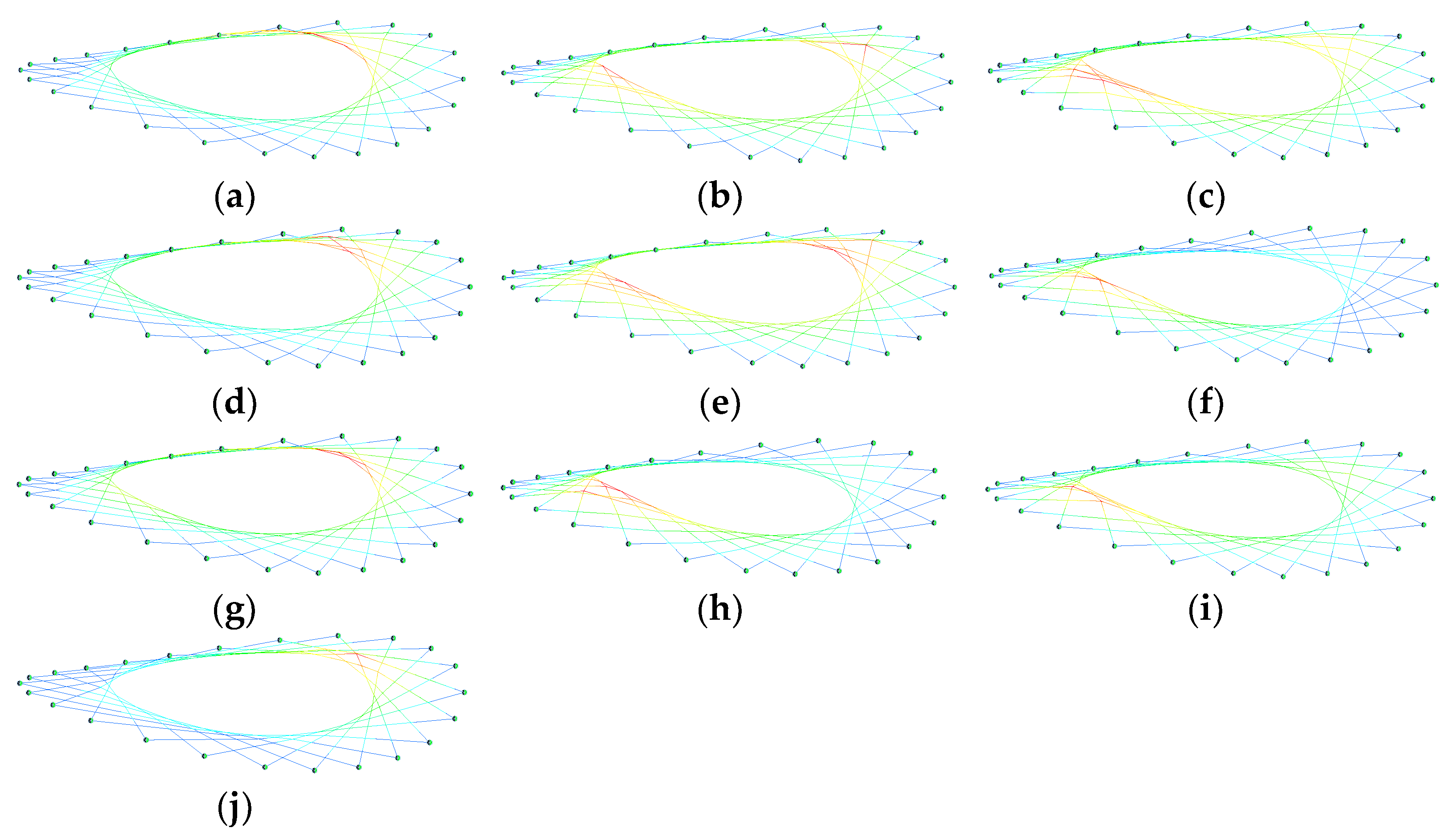
Figure 10 shows that mode shapes of some schemes including SE3/9 and SE3/10 are the apparent local motion of the cable net, indicating that local structural stiffness is significantly weakened, which is usually unacceptable. The mode shapes of other schemes comprise the overall motion or a slight local motion in the cable net.
From the analysis above, it was found that when deleting three virtual rings, displacements are the most sensitive to deleting cable clamps, the natural vibration period comes in second, and the tension is not sensitive. Since SE3/1 causes the least growth in MT and DP and growth in T comes in second, SE3/1 in which virtual rings II, III, and IV are involved is selected as the best scheme among the deletion of three virtual rings. It was found that when deleting cable clamps on three virtual rings, deleting the first three rings near the inside boundary of the LSHCS causes the smallest effect.
3.4. Deleting Four or Five Virtual Rings
Table 6 shows the results of the schemes of deleting four or five virtual rings. It is shown that all schemes induced an increase in
DP, SE4/1 had the smallest increase in
DP compared with SE0, with a growth of 180.50%, while the largest growth was 603.10% in SE5/1. It is shown that all schemes induce an increase in
MT, SE4/1 has the smallest growth in
MT by 19.28%, and SE4/5 causes the largest growth by up to 92.70%.
Table 6 also shows that all schemes induce an increase in
T, indicating that the overall structural stiffness becomes weaker. SE4/2 has the smallest growth in
T by 39.89%, followed by SE4/1 with a growth of 42.14%, while SE5/1 caused the worst effect by 131.30%.
Figure 11 shows that the mode shapes of some schemes including SE4/5 and SE5/1 comprise the apparent local motion of the cable net, and the two schemes are not acceptable. The mode shapes of other schemes comprise the overall motion or the slight local motion of the cable net.
From the analysis above, it was found that when deleting four virtual rings, displacements are the most sensitive to deleting cable clamps, the natural vibration period comes in second, and the tension is not sensitive. Since SE4/1 causes the least growth in MT and DP and growth in T comes in second, SE4/1 in which virtual rings II, III, IV, and V are involved is selected as the best scheme when deleting four virtual rings. It was found that when deleting cable clamps on four virtual rings, deleting the first four rings near the inside boundary of the LSHCS causes the smallest effect.
4. Conclusions
The loop-free single-layer hyperbolic cable net structure is a new type of tensile cable structure for buildings, and it can overcome the disadvantages of key elements and the high tension in loop cables. The imperfection of the LSHCS is that cable clamps near the inside boundary are redundant. The static behavior and dynamic characteristics of the designed schemes for deleting cable clamps are carried out in this paper. The possibility of deleting some redundant cable clamps is verified, and the guidelines for deleting cable clamps are explored. The conclusions are as follows.
Firstly, results show that SE1/1, SE2/1, SE3/1, and SE4/1 are the best cable clamp deletion schemes for their respective levels. It is concluded that for all levels of deleting cable clamps, schemes involving the virtual rings of cable clamps closest to the inside boundary of the cable net cause the smallest effect on static behavior and dynamic characteristics.
Secondly, the results show that displacements are the most sensitive to deleting cable clamps, the natural vibration period comes in second, and the tension is not sensitive with growth rates of 6.09%, 5.11%, 15.97%, and 19.28% in the best schemes of each level. It is concluded that deleting cable clamps affects the structural stiffness significantly, but the bearing capacity is not seriously affected.
In the end, although structural stiffness decreases due to the deletion of cable clamps, the LSHCS is a stable and stiffened structure. Its structural stiffness can be easily improved by increasing pretension, or the cross-section area of cables can be improved to meet the requirement of design specifications. Since deleting cable clamps near the inside boundary causes the smallest effect, removing redundant cable clamps in the dense part of the cable net is feasible.


