3.1. Modeling of the Grid Structure
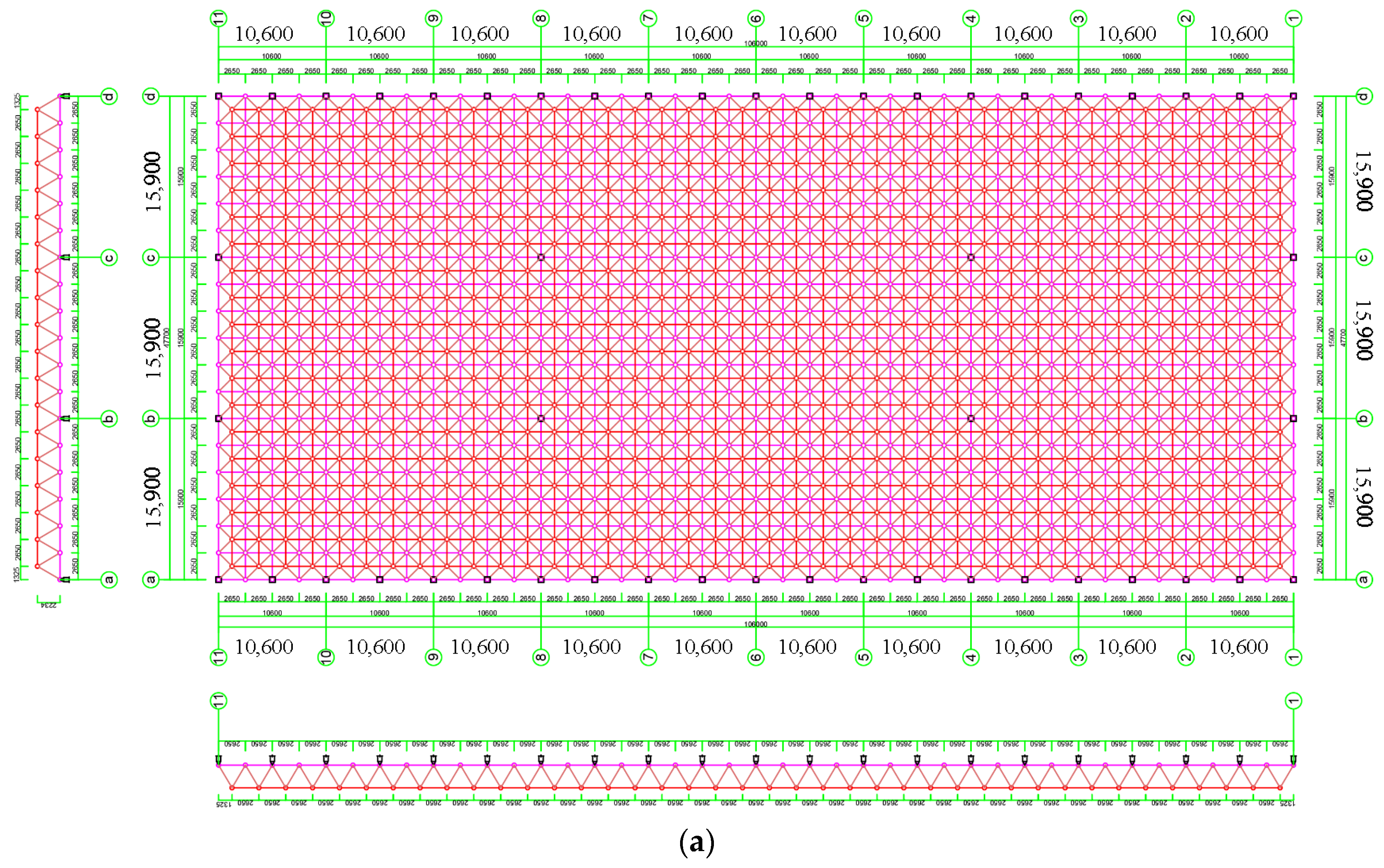
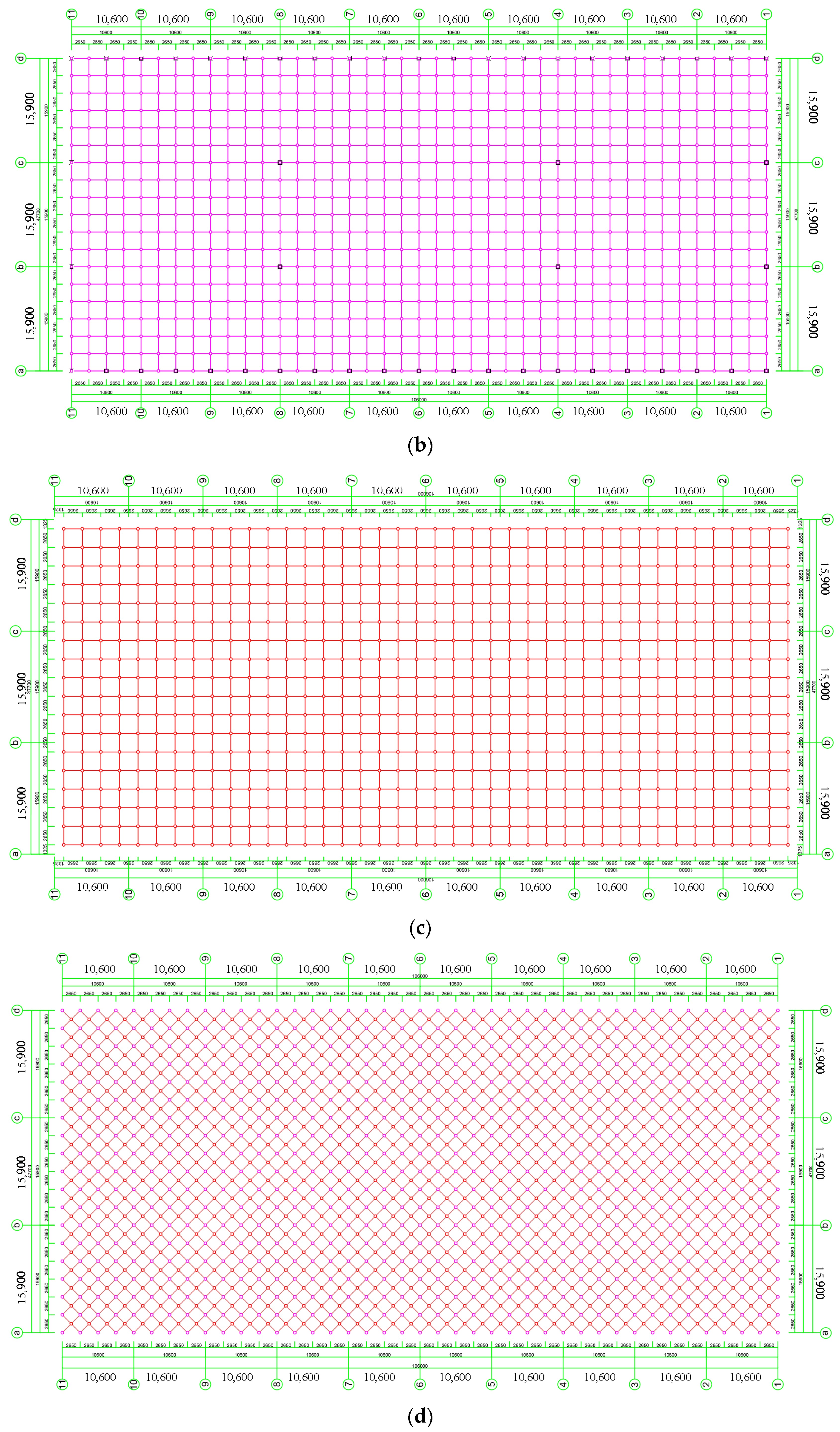
The finite element analysis software Abaqus is used for the modeling of the grid structure. The dimensions of the grid are approximately 108 m lateral and 48 m longitudinal. Preliminary simulation results indicated that the node with the largest deflection was located in the center of the grid, and the bearing web rod was under great stress. Therefore, a preload analysis is carried out for the five spans at the center of the whole grid and the section size of the web rod at the support is enlarged to enhance structural resistance.
The model of the grid structure is shown in
Figure 6. In order to study the influence of an insufficient preload of bolted joints on the mechanical performance of the whole grid structure and the normal stress of the local members, the middle part of the grid model is simplified. A simplified model can greatly shorten the calculation time. All grids are replaced by three-dimensional line components, except the five inverted quadrangular pyramid grids in the transverse and longitudinal spans. Spherical joints were set at the middle support, and all elements are merged into a single entity.
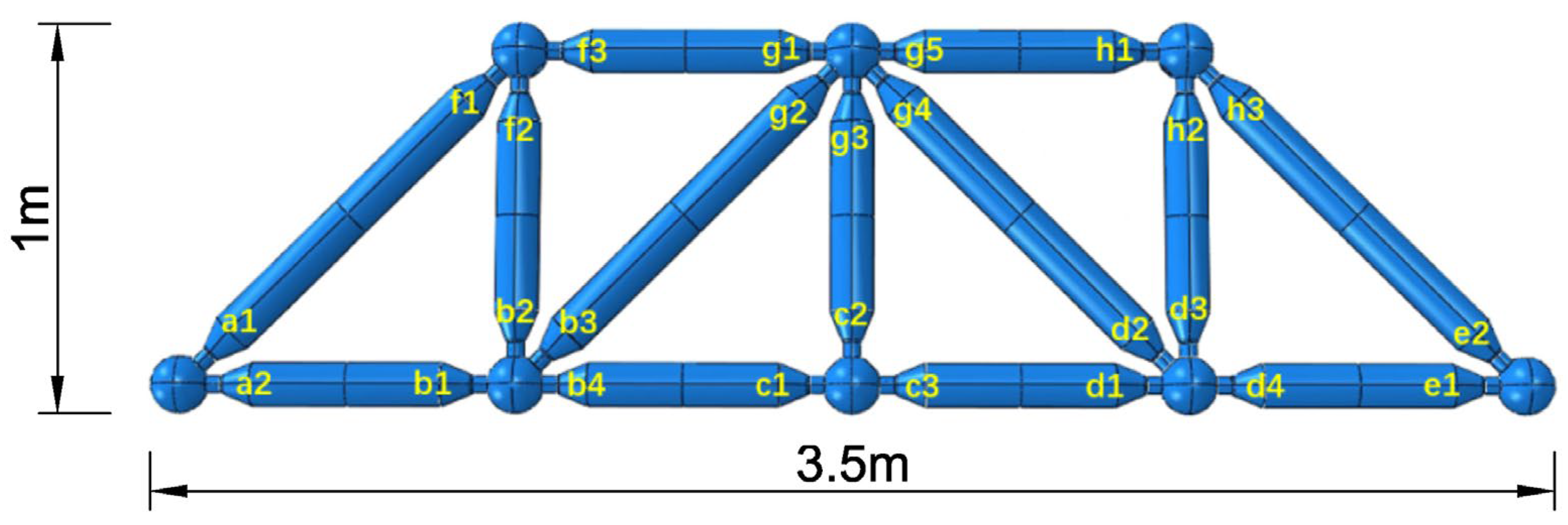
The inverted quadrangular pyramid model in the middle span is shown in
Figure 7. The diameters of upper and lower chord longitudinal rods are 114 mm, and 88.5 mm, and the wall thickness is 4 mm for all. The diameters of the transverse rods are all 180 mm, and the wall thickness is 10 mm. The diameters of the lower and upper chord rods are 220 mm and 200 mm, respectively.
All the elements in the model use the bilinear model. The upper and lower chord rods, cone heads, and sleeves use Q235 materials, and the web rods use Q345 materials. For material Q235, the yield strength is 235 MPa, the ultimate strength is 370 MPa, and the plastic strain is 0.06. For material Q345, the yield strength is 345 MPa, the ultimate strength is 470 MPa, and the plastic strain is 0.06. The bolt ball uses 45# steel. The yield strength of the bolt ball is 365 MPa and the ultimate strength is 660 MPa. The bolt uses 40Cr steel. The yield strength of the bolt is 430 MPa and the ultimate strength is 950 MPa. The elastic modulus is 207 GPa. The Poisson’s ratio is 0.3.
The first three analysis steps are used to apply the preload, and the last one is used to apply the load to the grid. According to JB/T 6040-2011 [
25], 250 kN preload is required to tighten M22 grade bolts and M30 grade bolts need 400 kN, while M56 grade bolts need 1500 kN. The B31 element is selected for the beam element of the grid part, the C3D4 element for the bolt-ball element, and the C3D8R element for the remaining elements.
The XYZ displacement and rotation of all column nodes except for the inverted quadrangular pyramid are constrained, and the column layout is shown in
Figure 6. A spherical node is created at the lower chord node of the middle span column and its six degrees of freedom on the lower surface are constrained.
3.3. Discussion of Results
According to GB 50017-2017 [
26], when a large span space grid is used as a roof, the calculation formula of maximum allowable deflection [
f] is as follows:
where
L is the short span of the grid.
The maximum allowable deflection of the grid is 190.8 mm. The simulation results show that when the maximum deflection of the grid reaches 190.8 mm, the allowable bearing capacity of the grid is 20.66 kN. Per GB 50017-2017 [
26], the design value of tensile, compressive, and bending strength for Q235 steel, with a thickness of less than 16 mm, is 215 MPa. The design value of tensile, compressive, and bending strength for Q345 steel, with a thickness of less than 16 mm, is 305 MPa.
The maximum normal stress of the lower chord rod under actual working conditions in all health conditions are CF (74.73 MPa), FI (74.89 MPa), LF (29.65 MPa), and FO (30.07 MPa). The normal stress of the upper chord and web rods are shown in
Table 3 and
Table 4, respectively.
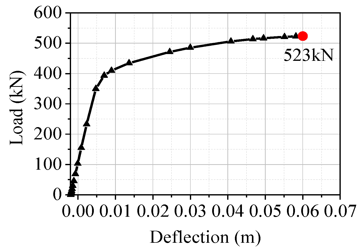
To better determine the law of the force variation, the relationship between the center deflection and the load variation of the grid is further studied. The load-deflection curve of the joint in the lower chord at the maximum deflection of the grid during the first load analysis step is shown in
Figure 9a, which is typically linear.
Figure 9b is the upper chord load-deflection curve at the location where the deflection is the highest, where u
max refers to the deflection at the location, which is 0.055. The upper and lower chords in the middle region enter the elastic-plastic stage with the increase in load, and the slope of the curve begins to decrease. When the upper chord joint load reaches 10 kN, the structure starts to experience an elastic-plastic change, and the mid-point deflection increases rapidly.
When the second load analysis step reached 6.88 kN, the rods around the web rod of the mid-span support entered the yield stage, as shown in
Figure 10a. The yield rod continued to spread from the mid-span support to the surrounding area after the rod near the web rod had entered the yield stage. When the upper chord load reached 20 kN, the central upper chord rod also began to yield, and the yielding upper chord rod continued to spread around with the increase of the upper chord load. According to the structural stress cloud diagram, it can be concluded that the load-deflection curve was more gentle because more rods began to yield, resulting in the overall structure entering the elastic-plastic stage. Due to the increase in the section size and material properties of the web rod at the support, the upper chord rod near the web rod first reached ultimate strength at the end of the second analysis step, as shown in
Figure 10b. The results show that the web rod at the support is the most unfavorable place for the grid.
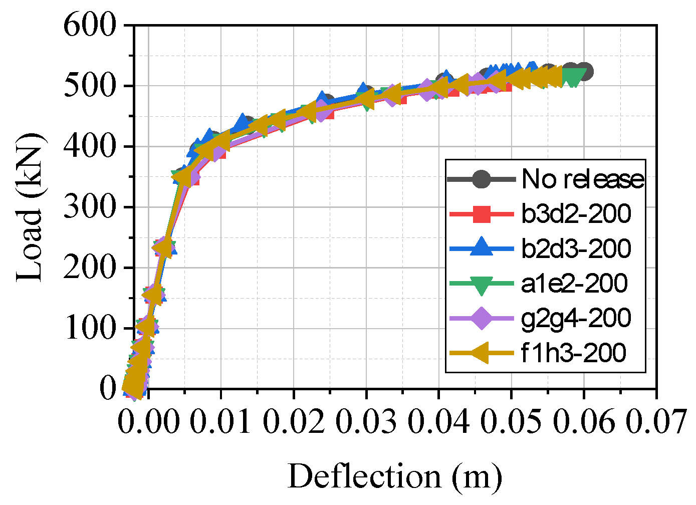
To investigate the influence of the bolt preload of different rods on the overall structural stiffness, all upper-chord transverse and vertical rods, web rods, and lower-chord transverse and vertical rods are released, respectively. The results show that no matter how much the preload was reduced, the release of the bar made the stiffness of the overall structure change very slightly. For example, when the upper chord load was 40 kN, the deflection after release only increased in the millimeter range. Therefore, the preload release of the inverted quadrangular pyramid has no significant effect on the stiffness of the whole structure.
There are two main reasons why the loss of preload does not affect the whole grid. First, the bending moment of the inverted quadrangular pyramid in the middle five spans is low, which does not highlight the improvement of the bending stiffness by the preload. Second, for the whole grid, releasing the preload of only a few members has a minimal impact on the whole structure. Therefore, it is necessary to study the influence of relaxing a small number of bolt rods on the normal stress of the surrounding local rods.
3.4. The Analysis of the Local Rod Simulation Results
The bolt in the inverted pyramid in the middle of the grid structure is set with a preload loss. When the upper chord load is 40 kN, the variation of normal stress in the surrounding local members is observed, and the relationship between the relaxation degree and the variation of normal stress is inferred.
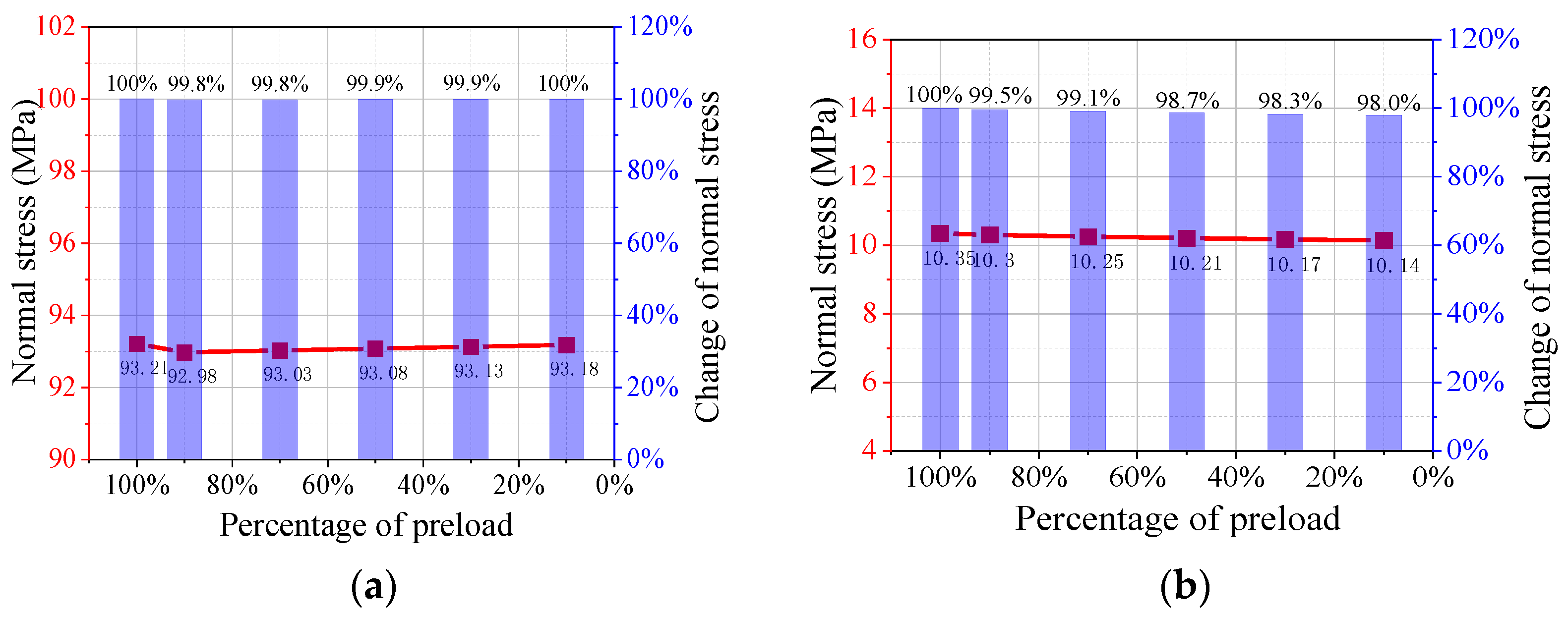
d3 from the upper chord rod was selected for the different degrees of preload loss. The relationship between the maximum normal stress of the surrounding rod and the preload is shown in
Table 5,
Table 6 and
Table 7. The percentages in the tables represent the comparison of the normal stress when the preload is released, to the normal stress when it is not released.
The rods with large changes were selected for analysis, as shown in
Figure 11. The results show that the normal stress of upper chord rods (
AD,
DG, and
GJ) in the same length direction can be increased obviously, by releasing the upper chord rod in the length direction. However, the normal stress of the upper chord in other length directions decreases, and the normal stress of the upper chord in the relaxation length direction increases gradually with the increase in the release degree.
Releasing the upper chord node also has a significant effect on the lower chord rod in the width direction. The normal stress of the LF rod in the width direction of the lower chord near the relaxation joint decreases obviously with the decrease in preload, while the normal stress of the rod in the width direction of the lower chord away from the relaxation joint increases slightly. The normal stress changes greatly for part of the web rods (FD, LM, LN, FE, and FH), and the trend is initially fast and then stable.
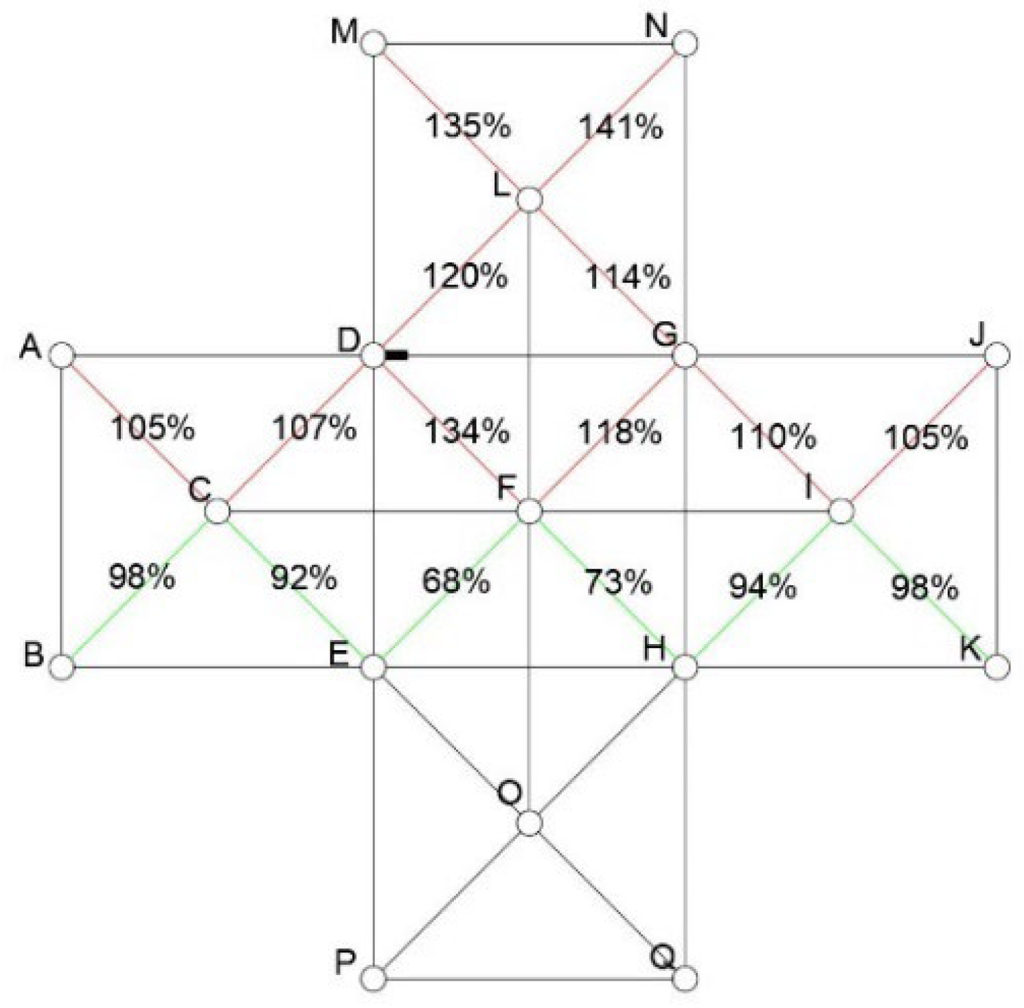
Figure 12 shows the variation in the normal stress of the web rod when the preload is 10% (red indicates that the normal stress increases and green indicates that the normal stress decreases). The results show that the normal stress of the upper part of the abdominal rod increases and the lower part decreases after the release of
d3. The amplitude of the increase (decrease) of the normal stress decreases with the increase in the release rod distance.
The
D joint sets the preload loss of the bolted joint in the width direction. As can be seen from
Figure 13, the effect on the normal stress of other members is negligible. However, in the length direction, the influence of the rod preload on the normal stress of the local rod is significant. It can be speculated that the preload loss of the upper chord rods in multiple length directions in the whole structure will affect its overall stiffness and bearing capacity.
If the percentage of preload is 90–100%, web rods LM, LN, and FD will reach the yield stress first. The rods FG and LD will enter the yield stage when the percentage of preload is 70–90%. Moreover, rod LG will reach yield strength when the percentage of preload is less than 70%. The rod that reaches the yield stage should be replaced in time, and the node that releases the preload should be screwed to the preload in a healthy state after the end of the step.
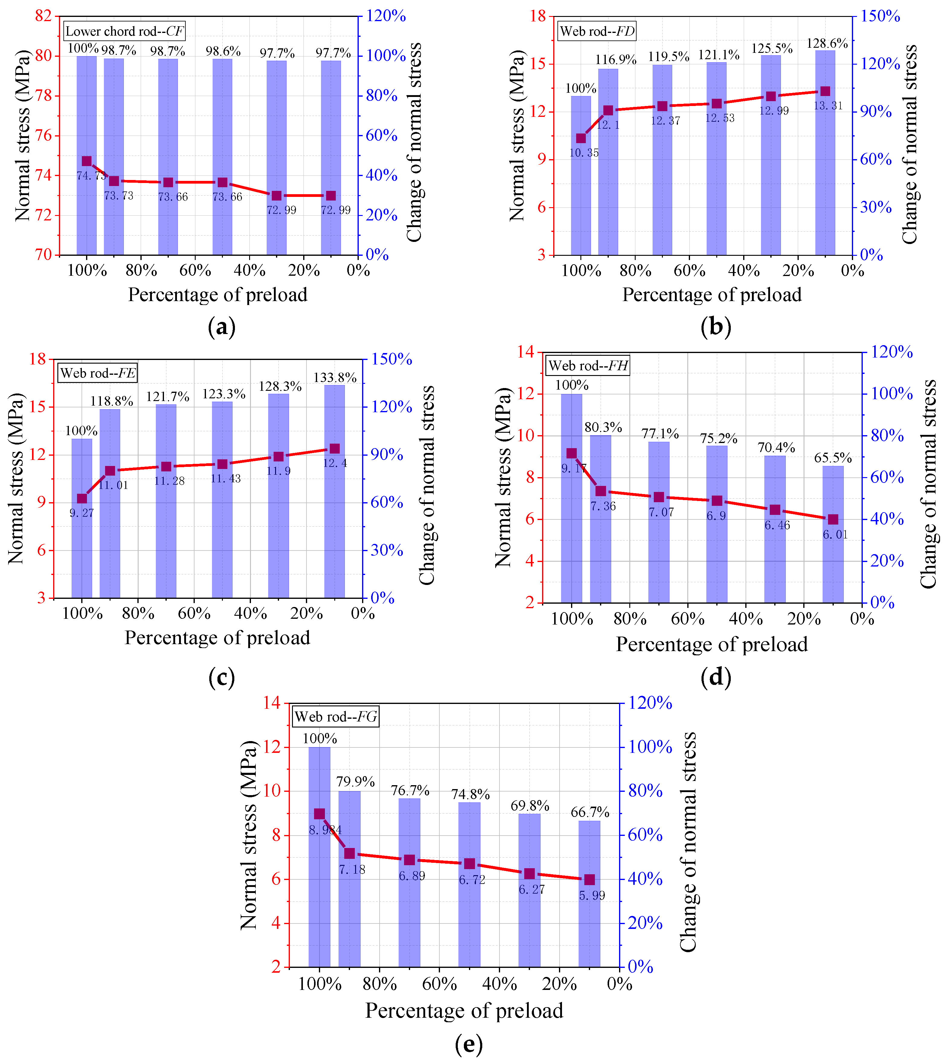
The rods with large changes were selected for analysis after releasing the preload of
f1, as shown in
Figure 14. The results show that the normal stress of the upper chord rods has no significant changes while that of the lower chord rods decreases with the decrease in preload. By releasing the normal stress of the upper chord in the length direction, the normal stress of
FD and
FE on the same side increases significantly. However, the normal stress of
FH and
FG on the other side decreases.
In the case of an insufficient preload at the end of the f1 rod, the FD and FE of the web rods will reach the yield stage if the preload is released. When the percentage of preload is less than 70%, rods LG and OH will also be at the yield edge. The rod that reaches the yield stage should also be replaced in time.
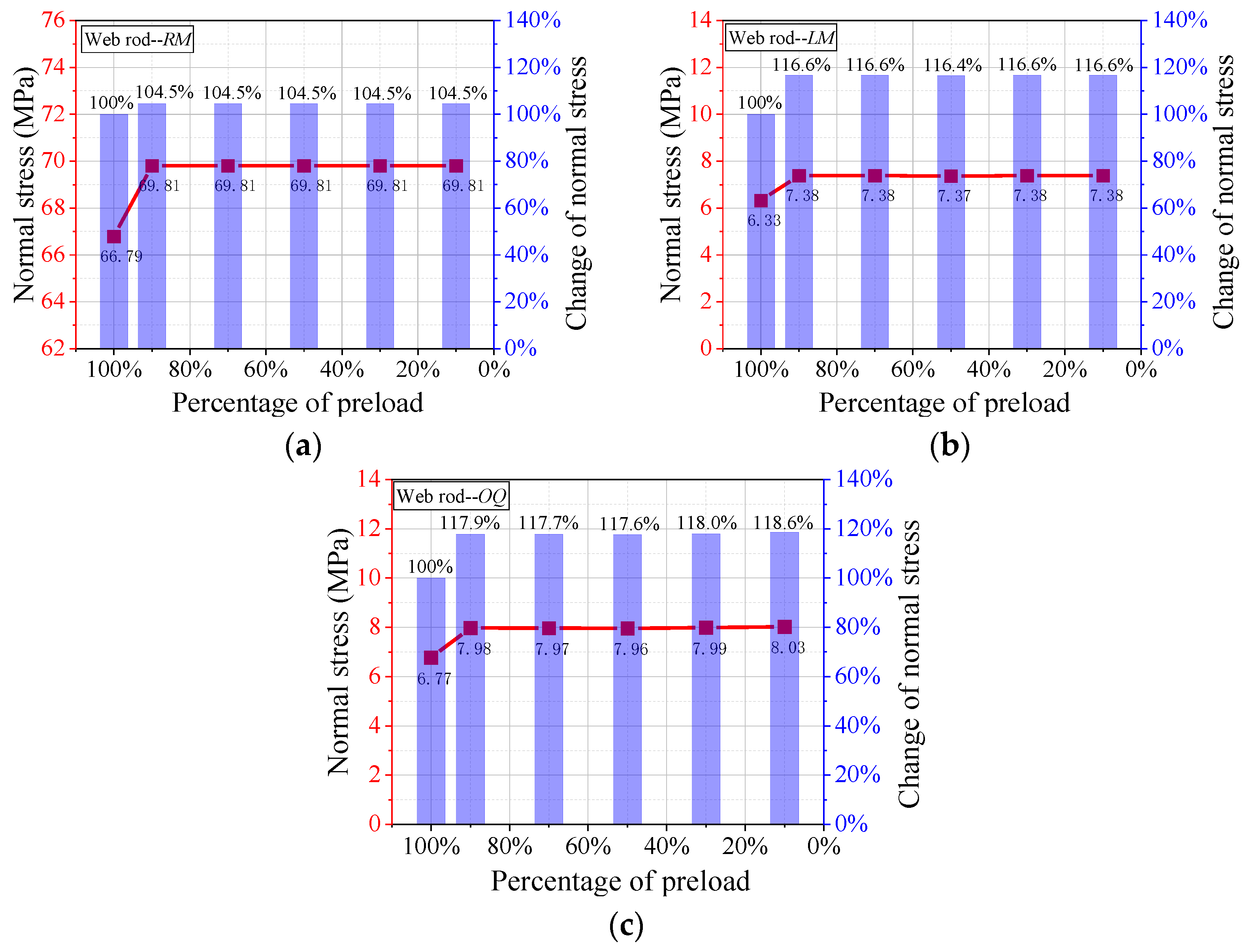
The release of the lower chord rod
f2 has a great influence on the normal stress of the surrounding web rod, and both the increasing and decreasing trends are initially fast and then stable, as shown in
Figure 15. Releasing the lower chord rod in the width direction has a certain influence on the normal stress of the distal upper chord rod. When the bolt percentage of preload is from 100% to 90%, the normal stress of the rod changes rapidly. From 90% to only 10%, the normal stress of the
RM rod is unchanged, as shown in
Figure 15a. Therefore, close attention should be paid to the initial stage of preload release because this stage has a rapid effect on the distal upper chord rod.
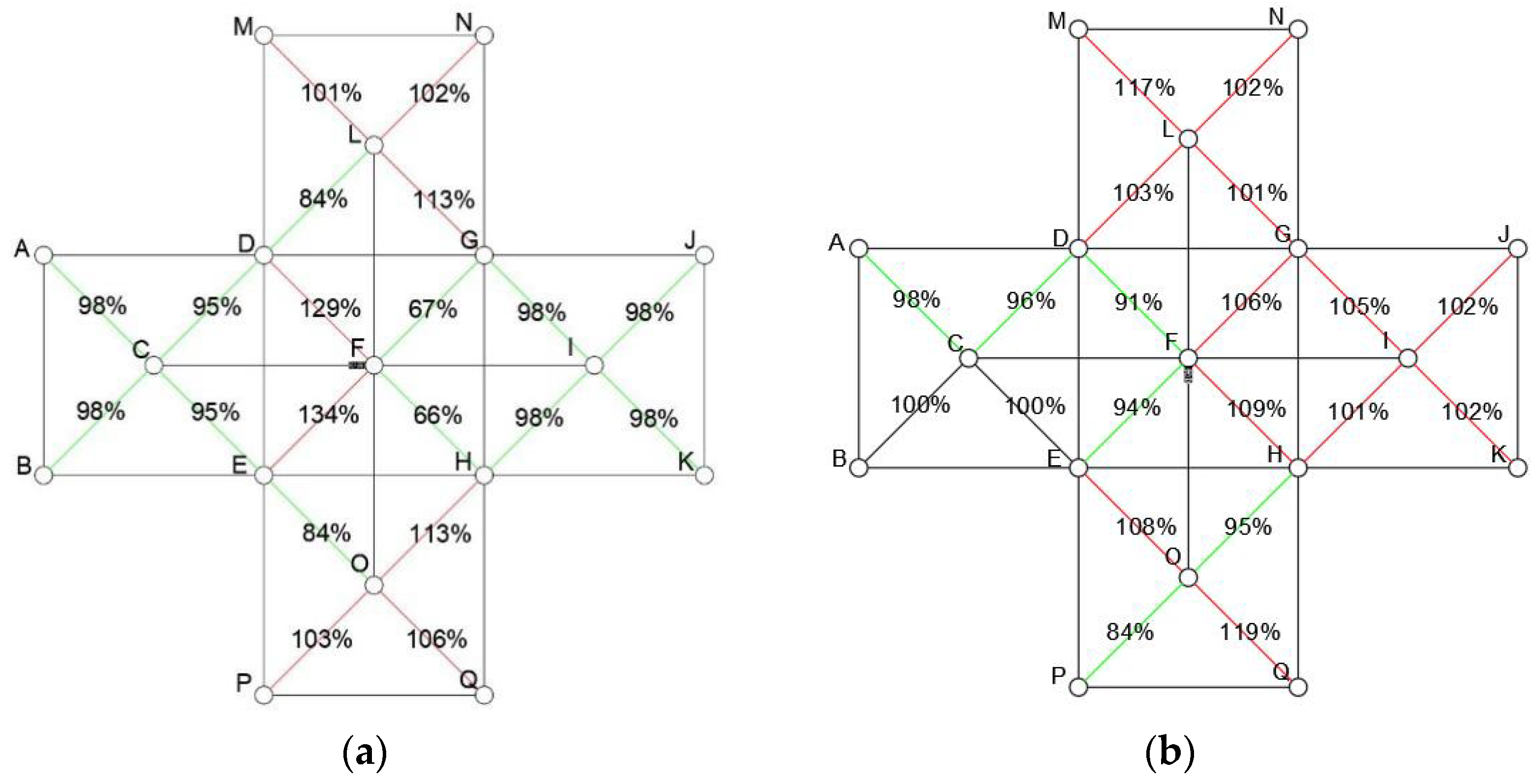
The effect of the normal stress on the surrounding web rod when the percentage of preload is 10% is shown in
Figure 16. The normal stress of the web rods near the release chord significantly increases and the normal stress on the other side significantly decreases after releasing the
f1 bolt. The normal stress of the web rod in the diagonal direction of the same width direction slightly increases, and the normal stress of the remaining web rods slightly decreases. The chord rod in the released width direction has little effect on the normal stress of its rod and other lower chord rods. The normal stress of the rods near the right side of
f2 increases, and the normal stress of the lower rods decreases. The results show that the normal stress of the rods around the released rod changes greatly, while the rods away from the released rods have less influence.
For rod f2 with insufficient preload, rods LM and OQ should be replaced in time. When the end of the slack rod is the lower chord with a small span, the normal stress of the surrounding rods changes rapidly between 90% and 100%, and it has no significant change. Therefore, it is found that when the preload of the lower chord rod in the direction of the smaller span is reduced, all the web rods in the two spans around the node should be detected immediately, and the rods with excessive normal stress should be replaced in time. However, if the preload is reduced by the web rod and the upper chord rod in the smaller span direction, the preload can be screwed to the healthy state in time.
In the actual grid, the preload of bolt rods in the direction of the large span takes an important role and the preload of the upper chord has a greater influence. As the preload of a bolt rod decreases, the normal stress of the surrounding rods will change. However, if the string bolt in the width direction is not in the state of healthy preload, the normal stress of the surrounding rods will suddenly change. The preload of the web rod and upper chord rod with a small span has little effect on the normal stress of the surrounding rods. Therefore, it is necessary to pay attention to the preload of the lower chord rod in the smaller span direction.


