Abstract
The all-steel attached lifting protection platform widely employed in recent years has always suffered from self-weight issues and corrosion. Aluminum alloy is the ideal option for steel owing to its low bulk density and resistance to corrosion and rust. However, its elastic modulus is insufficient, causing the deformation of the structure to easily exceed the limitation of the Code for Design of Aluminum Alloy Structures. Therefore, this study recommended using sorbite stainless steel with high strength and a reasonable price as the guide rail of a protection platform having a significant force in conjunction with aluminum alloy to maximize their advantages. Regarding the overall structure, Midas GEN was used to verify whether their deformation adheres to the specifications. For exploring the stiffness of exact nodes, the wall-attached support was modeled by Abaqus, discovering that its maximum composite deformation is 0.725 mm, and its highest stress (490.2 MPa) appears at the intersection of the bottom and the side plate. Additionally, the influence of three key factors (the cantilever height of the protection platform, the horizontal spacing between two wall-attached supports, and the sectional size of the main frame fittings) on the structural deformation was investigated. Finally, the cost per extension meter was compared between the all-steel and the novel sorbite stainless steel-aluminum alloy attached lifting protection platform. The findings of the aforementioned works can effectively guide the design and construction of this novel structure and play a crucial role in its popularization and application.
1. Introduction
The conventional scaffold cannot satisfy the needs of high-rise building construction owing to the protracted construction duration, high consumption of resources, and inadequate safety. However, the attached lifting protection platform (the new scaffold) comprises a frame structure, wall-attached supports, lifting motors, control devices, and anti-tilt and fall devices that can compensate for the above deficiencies [1]. Currently, this structure is made mainly of steel susceptibility to corrosion, significantly reducing its safety and reusability [2]. Compared to steel, aluminum alloy offers the advantages of corrosion and rust prevention, no requirement for paint, low bulk density, green environmental protection, and a high reuse rate [3,4]. Nevertheless, its elastic modulus is insufficient, causing the structural deformation to easily exceed the limitation of the Code for Design of Aluminum Alloy Structures [5]. The recently developed sorbite stainless steel has excellent strength, acceptable price (12,000 RMB/ton), and strong corrosion resistance, which could mitigate this issue [6,7,8]. Therefore, this study proposed using sorbite stainless steel as the guide rail of a protection platform having a significant force in conjunction with aluminum alloy to maximize their respective advantages. This innovative structure is environmentally friendly and pollution-free, embodying the notion of sustainable development [9,10,11].
International research on aluminum alloy structures has steadily progressed. European and American nations created a comprehensive General Code for the Design of Aluminum Structures in 2002 [12]. In order to develop a design code suitable for Chinese conditions, Li et al. began to use a combination of theoretical and experimental analysis to research the calculation of aluminum alloy fillet welds and bolted connections [13]. Guo et al. performed experimental and numerical simulations of 6061-T6 aluminum alloy-eccentric pressurized members to construct a precise prediction equation [14]. Then, the relative code was established in 2007 [5]. To understand the applicability of this code to new type 6082-T6 aluminum alloy H-shaped members manufactured in China, Yang et al. undertook several eccentric compression tests [15]. Abaqus was used to build a finite element model based on the test data, and an extended parameters analysis was completed [16,17,18]. The calculation methods for its load-carrying capacity in several international codes were validated, and recommendations were made for modifying key parameters in Chinese codes.
Additionally, research on stainless steel materials has gradually deepened. Macdonald found the law that the strain hardening coefficient increased with strain and fitted an expression of the strain hardening index based on the experimental data [19]. The modified R-O Equation has high precision but only applies to specific test pieces. Rasmussen, to more precisely analyze the impacts of stainless steel material nonlinearities, created a complete constitutive model integrating the diversity of material based on the three parameters of the original R-O model and the expressions for Winter’s effective width [20]. Hradil discovered that the tangent modulus approach in the American Code neglected the effect of geometric imperfections on the stability of compression members [21]. Therefore, the Euler critical force obtained from the American code was inserted into the European code to recalculate the stability coefficient of the component. Yuan conducted tensile and compressive mechanical properties tests on duplex stainless steel with varying thicknesses and confirmed that the modified two-stage R-O model was a better fit for its stress-strain relationship [22,23]. In 2007, Zheng et al. tested tension and compression on a batch of Chinese austenitic stainless steel and suggested a simplified three-stage constitutive model based on the test data and Quach’s constitutive model [24,25,26]. Huang et al. subsequently utilized existing models to describe the stress–strain curves of sorbite stainless steel and determined that Zheng’s model became the most accurate [27].
Regarding the all-steel type attached lifting protection platform, Yu et al. experimentally and numerically analyzed the multi-story portal composite steel scaffold in detail [28]. Using stochastic finite element theory, Hao et al. studied the mechanical characteristics of steel pipe scaffolds with various defect configurations [29]. In 2010 and 2019, the Ministry of Construction of the People’s Republic of China issued the “Technical code for safety of implementation scaffold practice in construction” [30] and the “Safety protection platform for adhering type lifting operation for building construction” [31] to regulate their design and construction. The utilization of aluminum alloys in the scaffolding industry is in the exploratory phase. Wu simulated and evaluated the aluminum alloy attached scaffold in the project and concluded that the construction risk of lifting the frame under the wind load participation combination is significant [32]. Wang et al. proposed quality control procedures for super high-rise structures in 2022 based on the “aluminum formwork + climbing frame” construction method [33]. However, there is little investigation into using stainless steel materials in the scaffold.
Consequently, a finite element model of the attached lifting protection platform was developed using the Midas GEN to address the abovementioned issues in this study. Then, according to the characteristics of stainless steel and aluminum alloy materials, the frame structure was optimized and adjusted, and a novel protection platform was redesigned. Simultaneously, the whole structure and critical nodes were modeled to validate their deformation. Moreover, the influence of the cantilever height of the protection platform, the horizontal spacing between two wall-attached supports, and the sectional size of the main frame fittings were focused on in detail. When the lifting platform is faced with the problem of large deformation, the material of the guide rail can be replaced by sorbite stainless steel, and the frame structure can be selected according to the three aspects. Hopefully, these findings can effectively guide the design and construction of the novel sorbite stainless steel-aluminum alloy attached lifting protection platform and play a crucial role in its popularization and application.
2. Midas GEN Finite Element Model Verification
2.1. Experiment Overview
2.1.1. Structural Layout
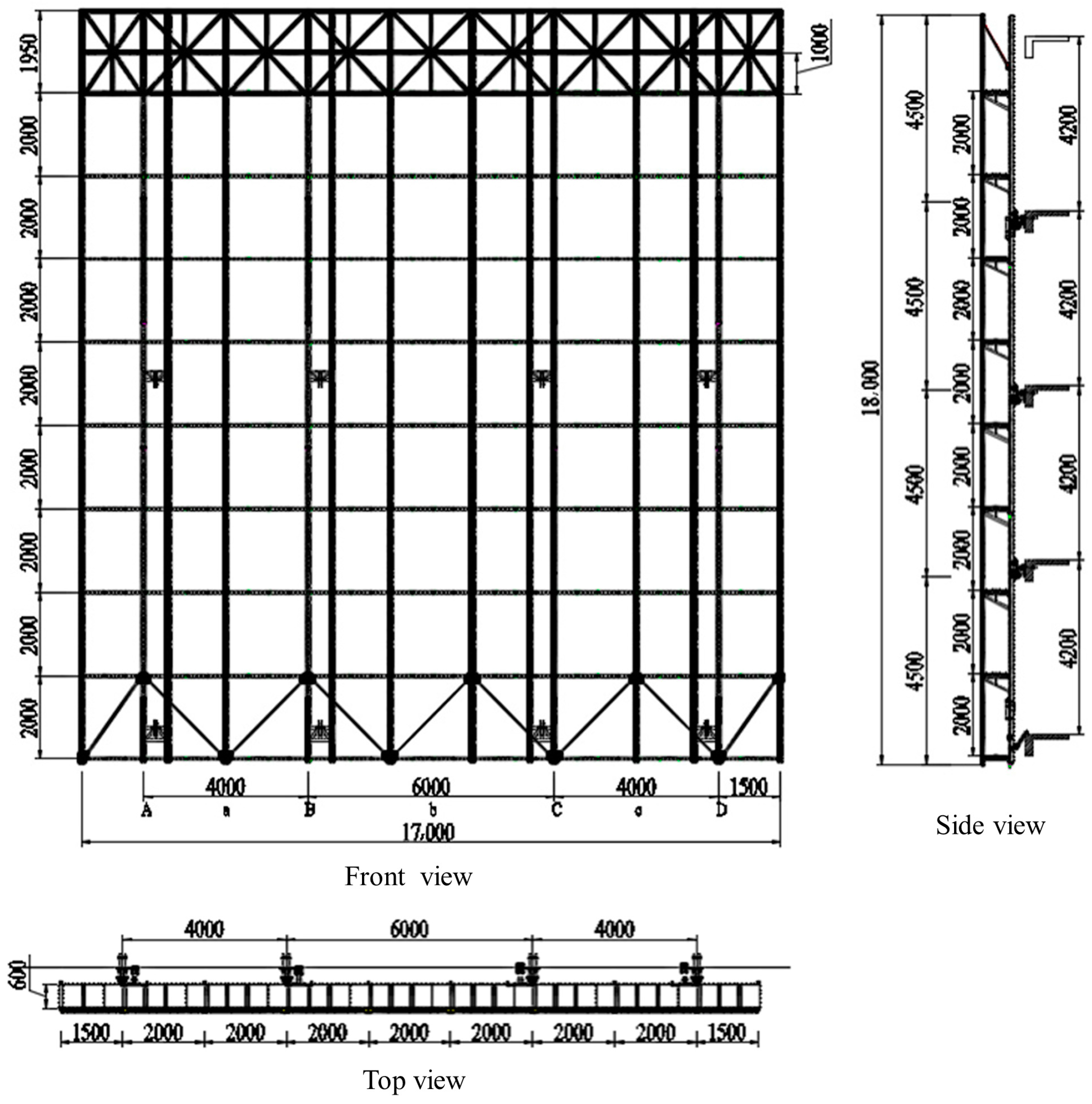
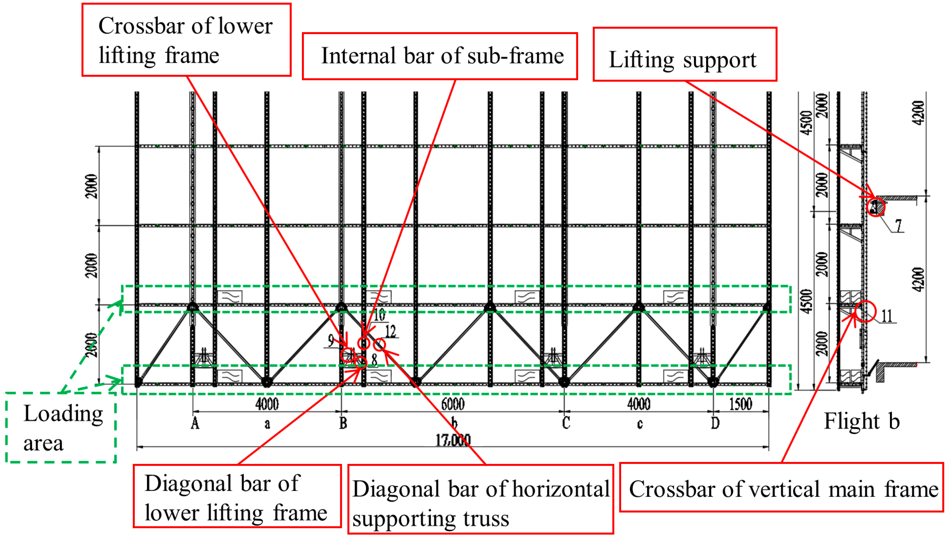
The specimen for this verification test is an all-steel attached lifting protection platform with nine layers and three spans, composed of internal and external vertical bars and crossbars of the main and sub-frame, horizontal supporting trusses, wall-attached supports, lifting motors, and control operating systems (Figure 1). According to Safety Technical Specification for Attached Lifting Scaffolding in Hunan Province [34], the vertical distance of the vertical pole of the frame should not be more than 2.5 m, and the step distance of the frame should not be more than 2 m. Therefore, we consider setting the mesh size to 2000 × 2000.
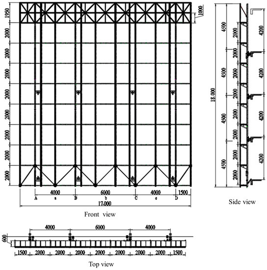
Figure 1.
Structural layout of all-steel attached lifting protection platform.
2.1.2. Loading Scheme
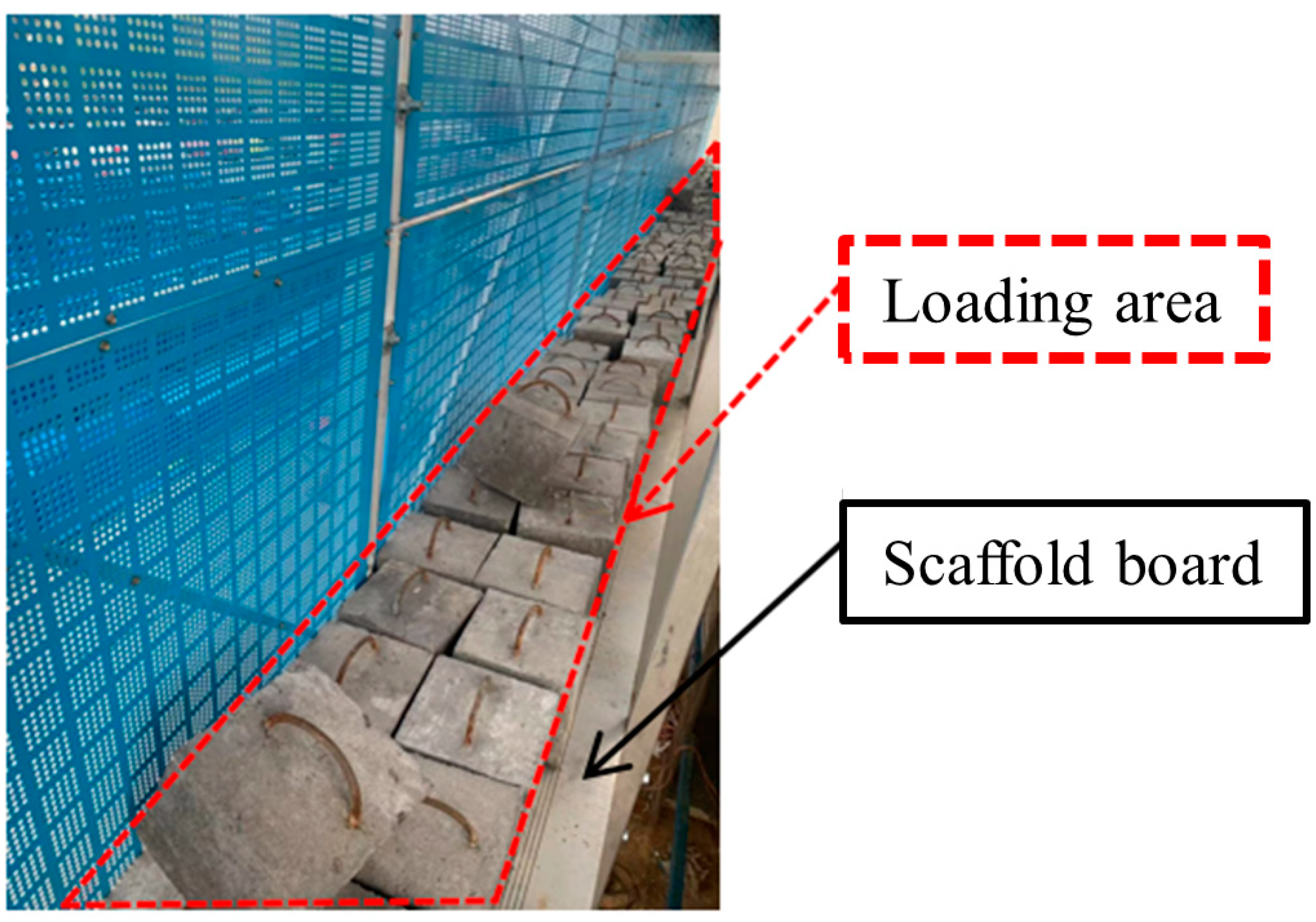
In this experiment, the static loading technique was employed with no wind, and the pressure device was a concrete block of 10 kg. As shown in Figure 2, regions were loaded under two service conditions of the structure: operating and lifting. According to the “Technical code for safety of implementation scaffold practice in construction” (JGJ 202-2010) [30] and “Load code for the design of building structures” (GB 50009-2012) [35], there are two levels of load under the operating condition. The first stage consists of the standard uniformly distributed load of 3.0 kN/m2 and the second stage of 3.75 kN/m2. Under these circumstances, the electric hoist (lifting motor) did not function, and the concrete blocks were uniformly distributed throughout the first and second layers of the frame body. Under the lifting condition, the pressure was divided into single-stage loading of 0.5 kN/m2. The electric hoists were concurrently activated at each position, and the frame was raised constantly.
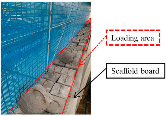
Figure 2.
Loading diagram.
2.1.3. Measurement Points Arrangement
- (1)
- Strain measurement points
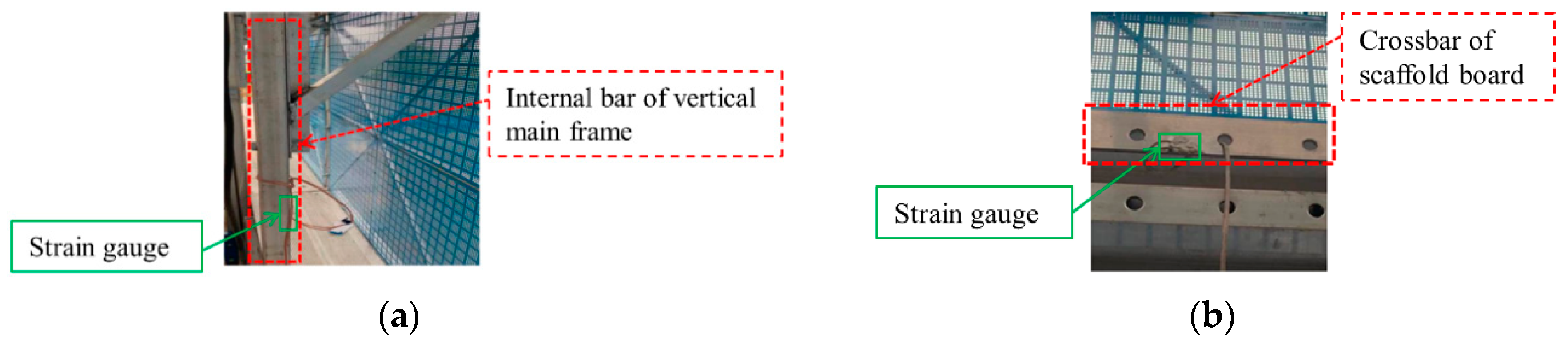
Twelve strain gauges were positioned at the critical positions of the frame body (Table 1, Figure 3 and Figure 4). The data were collected by DH3815N static strain testing equipment. Figure 5 depicts actual pictures of several strain gauges.

Table 1.
Location of strain measurement points.
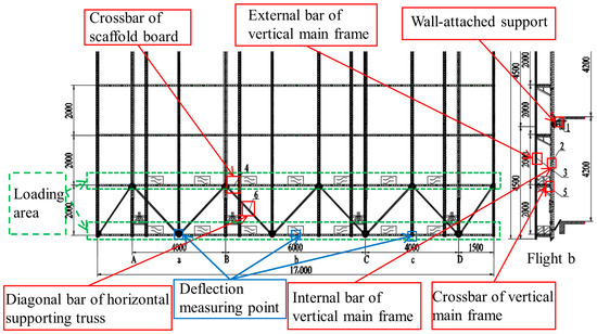
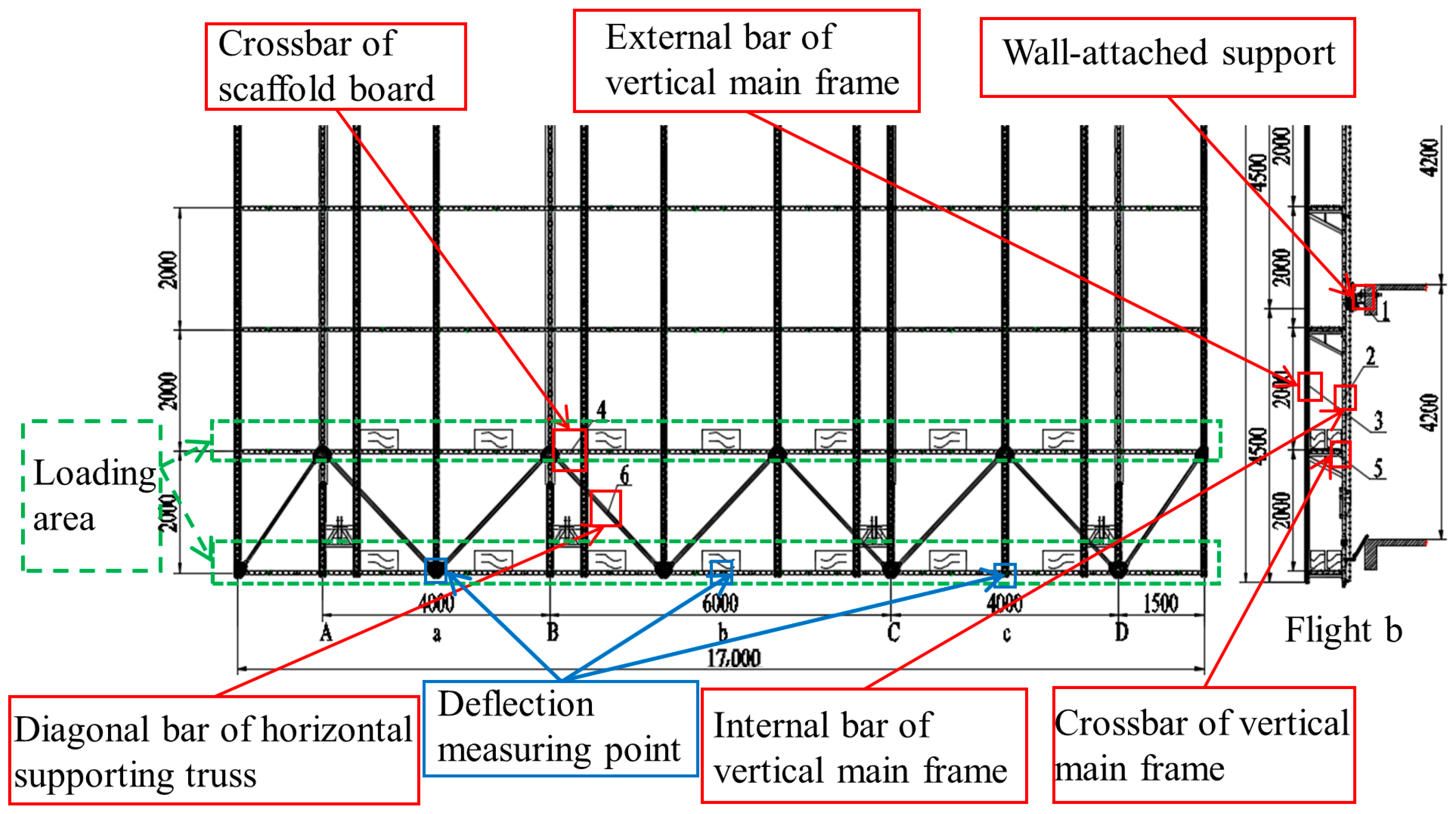
Figure 3.
Layout of strain measurement points under operating condition.
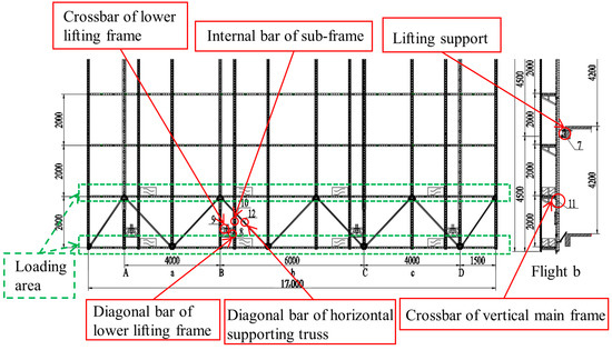
Figure 4.
Layout of strain measurement points under lifting condition.
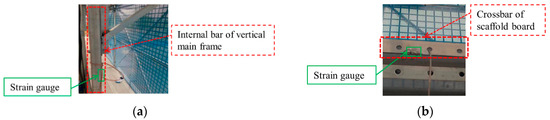
Figure 5.
Actual pictures of several strain gauges. (a) Internal bar of vertical main frame. (b) Crossbar of scaffold board.
- (2)
- Deflection measurement points
Three dial indicators were arranged vertically at the bottom of the horizontal supporting truss to measure the deflection of the specimen (Figure 2). Moreover, the motors of the specimen at the unified horizontal plane were chosen. The theodolite was utilized to determine the relative displacement of the two adjacent motors during lifting and falling to evaluate the synchronous performance.
2.2. Establishment of Finite Element Model of All-Steel Attached Lifting Protection Platform
2.2.1. Material Properties
The electric gourd frame and other protection platform components were made of Q345 and Q235 steel, respectively. Their material properties are detailed in Table 2.
Table 2.
Material properties of all-steel attached lifting protection platform.
2.2.2. Connection Condition
In the actual test, the bolted connections (hinge joint) were between the vertical bar of the main and sub-frame with the longitudinal crossbar, triangular brace, grid frame, and diagonal bar of horizontal supporting truss; between the vertical bar of the main frame with electric gourd frame; among adjacent transverse crossbars; between the longitudinal crossbar with the connecting plate. The welding connections (shared or rigid joint) were between the internal bar of the main frame with the groove guide rail; between the groove guide rail with the circular guide rail and crossbars.
2.3. Comparison between Simulation and Experimental Data of All-Steel Attached Lifting Protection Platform
Because the comparison results were utilized to validate the simulation accuracy, only the stress and deflection corresponding to the measurement points of the frame body were considered under 100% and 125% standard load.
2.3.1. Operating Condition
From Table 3, Table 4, Table 5 and Table 6, it can be determined that the error between the theoretical and experimental data of stress and deflection at each measurement point of the frame is less than 7% and 5%, indicating that under these two service conditions, the finite element model can effectively simulate the whole process of deformation on the structure.
Table 3.
Comparison of simulation with experimental stress value under standard load.
Table 4.
Comparison of simulation with experimental stress value under 125% standard load.
Table 5.
Comparison of simulation with experimental deflection value under standard load.
Table 6.
Comparison table of finite element model and test deflection under 125% standard load.
2.3.2. Lifting Condition
The loading mode of the model corresponded with the test. Only the frame and electric gourd self-weight, simulated rope force, and live construction load were considered without wind load. Table 7 displays the comparison results of stress values. The error between the simulation and the experimental value of each measurement point of the frame body is less than 7%, validating the accuracy of the model.
Table 7.
Comparison of simulation with experimental stress value under lifting condition.
3. Establishment and Analysis of Whole Model of a Novel Sorbite Stainless Steel-Aluminum Alloy Attached Lifting Protection Platform
3.1. Establishment of Whole Model
3.1.1. Material Selection
The new sorbite stainless steel S600E has the exceptional features of high strength, superior corrosion resistance, and a low price, so it has significant competition and widespread adoption potential in engineering applications [36,37,38]. In consideration of the deformation characteristics of the protection platform, S600E was chosen as the material for the primary load-bearing component (guide rail), and the van Mises model was implemented in the Midas Gen 2019 software. Table 8 and Table 9 illustrate its performance and specifications. Currently, 6061-T6 (T signifies a particular heat treatment condition) aluminum alloy is primarily used for building structures in China [39,40,41,42,43,44]. This series has outstanding resistance to corrosion and strength and is appreciated in the manufacturing industry because of its excellent machinability. Therefore, 6061-T6 aluminum alloy was selected to construct the remaining components (Table 8 and Table 9).
Table 8.
Material properties of novel sorbite stainless steel-aluminum alloy attached lifting protection platform.
Table 9.
Specifications and materials for each component of attached protection platform (unit: mm).
3.1.2. Connection Condition
The connections were identical to those described in Section 2.2.2, and the whole structure model is illustrated in Figure 6. Among them, red indicates the material of sorbite stainless steel and the rest is aluminum alloy.
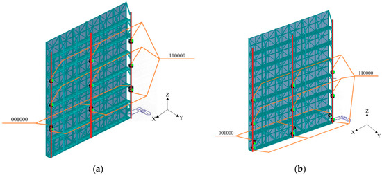
Figure 6.
Overall finite element model of proposed structure. (a) operating condition. (b) lifting condition.
3.1.3. Boundary Condition
Under the operating condition, the uppermost-row supports of the structure were set at a cantilever height of 4.5 m. Supports were arranged at vertical intervals of 3 m in each main frame and three rows of wall-attached supports at 3.5 m, 6.5 m, and 9.5 m, respectively. The latter were configured to restrict the X and Y-direction and the Z-direction displacement at 3.8 m (since the top brace of the wall-attached support has a certain length) (Figure 5).
The most adverse lifting condition is when the protection platform is elevated one floor before the topmost wall-attached supports are installed. Therefore, the uppermost-row supports of the protection platform were set at a cantilever height of 7.5 m. Supports were arranged at vertical intervals of 3 m in each main frame and with three rows of wall-attached supports at 0.5 m, 3.5 m, and 6.5 m, respectively. The latter were configured to restrict the X and Y-direction, and the Z-direction displacement was placed at the lifting point under the electric gourd frame (Figure 5).
3.2. Overall Deformation Analysis
The X-Z plane in the model represents the front of the protection platform. Therefore, most of the wind-induced deformation occurs in the Y-direction (The wind load is perpendicular to the direction of the safety net). The middle and side span wind load are 337.0 and 168.5 N/mm. The overall deformation of the sub-frame is equal to the sum of the deformations of the main and sub-frame, and the most significant Y-direction deformation of the protection platform occurs on the main frame. Hence, only the Y-direction deformation of the main frame was extracted.
Table 10 displays the location and magnitude of the maximum displacement under positive and negative wind pressure. According to GB 50429-2007, the allowable deflection value of aluminum alloy main members is , where is the calculation span, adopting two times the actual cantilever length. Clearly, all deformations of this novel sorbite stainless steel-aluminum alloy attached lifting protection platform meet the specification requirement. Most do not exceed the 70% limitation value. Notably, the Y-direction displacement under lifting condition with negative wind pressure reaches 76.9%. So, structural optimization is necessary.
Table 10.
Deformation of proposed structure under various working conditions and wind pressures.
4. Establishment and Analysis of Wall-Attached Support Model of Novel Sorbite Stainless Steel-Aluminum Alloy Attached Lifting Protection Platform
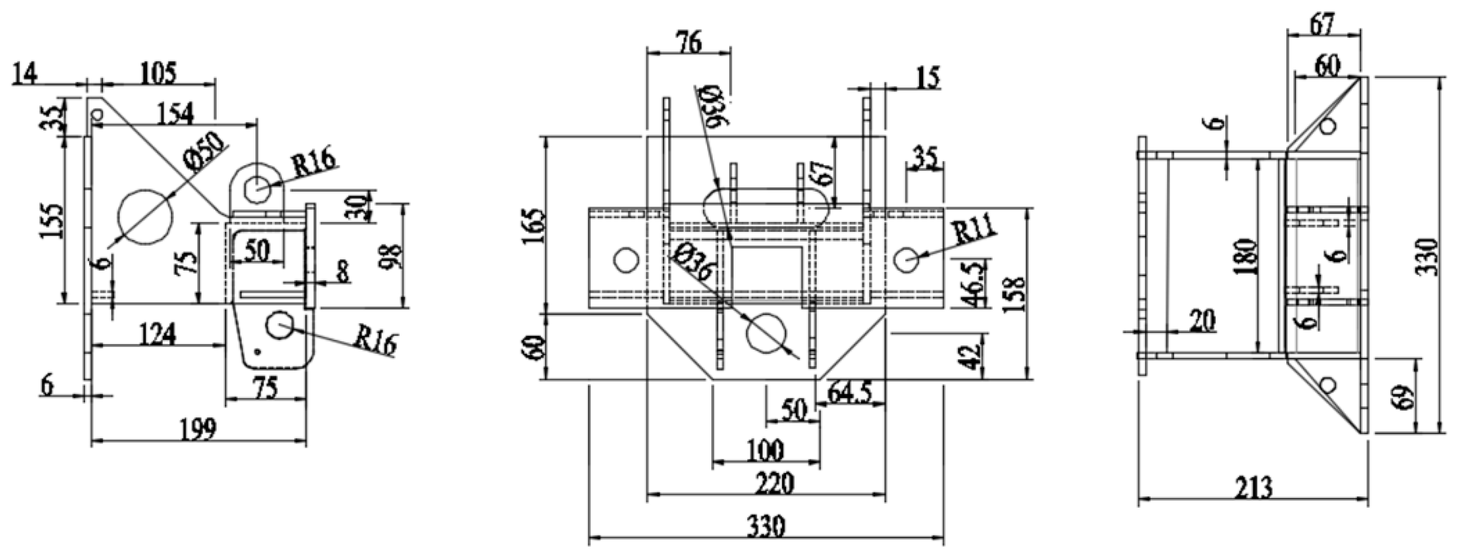
Under the operating condition, the entire weight of the structure rests on the wall-attached support. Hence, its stiffness is crucial. In this section, the refined finite element analysis of wall-attached support was carried out using Abaqus 2019. Generally, the plate thickness of the wall-attached support of the all-steel protection platform is 10 mm. To effectively use the strength of high-strength stainless steel and reduce the weight of the proposed structure, the plate thickness of the wall-attached support was set as 6 mm, whose detailed dimensions are shown in Figure 7.
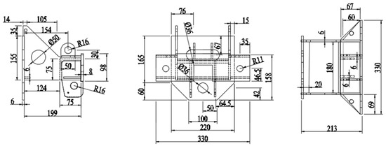
Figure 7.
Design drawing of wall-attached support.
4.1. Constitutive Relation of Materials
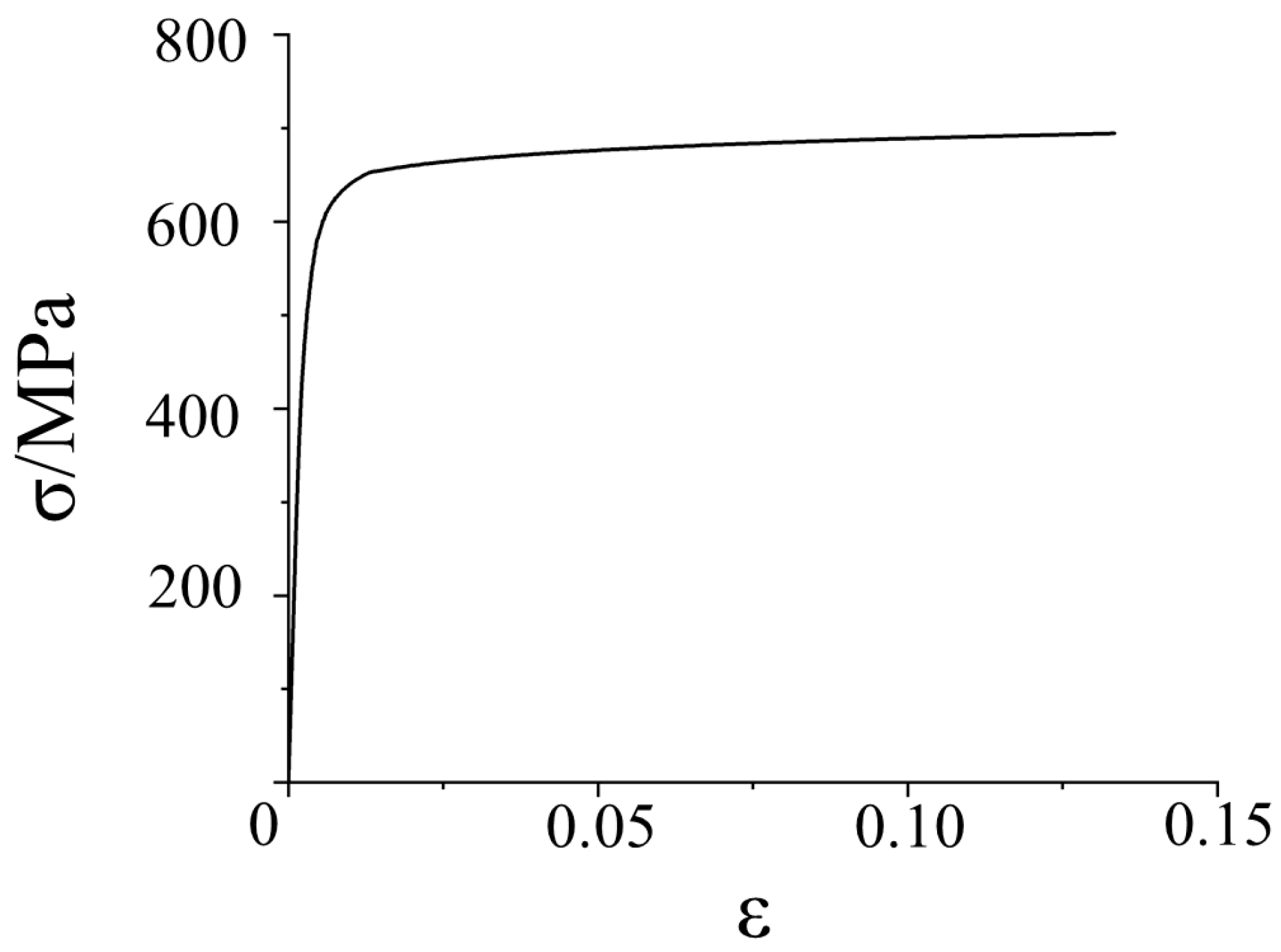
In 2017, Zheng et al. [24,25] developed a simplified three-stage function for stainless steel (Equation (1)). Among them, E0 represents linear elastic modulus; n represents strain hardening index; ε represents strain; ε1.0 represents corresponding strain; εu represents peak strain; σ represents stress; σ0.01, σ0.2, σ1.0, σn represents 0.01%, 0.2%, 1.0%, n% residual strain corresponding stress, where σ0.2 represents nominal yield strength. Subsequently, it was proved that this formula could describe the stress-strain curve of sorbite stainless steel S600E [27] (Figure 8). In this section, the true stress and strain of S600E were thus input into the finite element model through Equation (2). Among them, E0 represents linear elastic modulus; εnorm, σnorm represent nominal strain and nominal stress; εpl, σ true represent real strain and real stress, respectively.
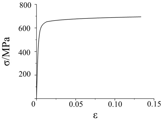
Figure 8.
Typical Stress-strain curve of S600E.
4.2. Element Selection and Boundary Condition
According to the features of the quadratic simplified integral element, it is the best option if it is not necessary to cope with high strain and displacement difficulties or complicated contact conditions. Therefore, in the modeling process, the twenty-node quadratic hexahedral reduction integral element C3D20R [45] was selected to simulate the whole wall-attached support. Because the wall-attached support must be anchored to the undeformed wall, a fixed discrete rigid body was established to simulate the wall and make hard contact with the bottom plate. The ring on the bolt hole of the bottom plate constrained the X, Y, and Z directions displacements.
4.3. Load Condition
With comprehensive reference to the provisions of the JGJ 202-2010 [30] and JGT 546-2019 [31], and considering the most unfavorable operating condition, each wall-attached support should be able to bear the design value of all vertical loads within the range of the electric gourd and multiply by the impact coefficient 2 (Ratio of dynamic deflection to corresponding static deflection). Meanwhile, the load non-uniformity coefficient was disregarded. In the horizontal direction, the maximum transverse load of a single wall-attached support was evaluated. It was caused mainly by the wind load (Y-direction) (the wind area of the upper middle support is the largest), although it was insignificant in the X-direction. According to the calculation, the maximum reaction force of the support in the Z and Y-directions is 80,600.7 and 22,371.5 N. This section converted the vertical and transverse force into a uniformly distributed load of 231.8 and 5.3 N/mm² on the top bracing plate and the fixed plate of the guide wheel seat. The angle between the top brace and the vertical direction was 15°.
4.4. Finite Element Analysis of Wall-Attached Support
4.4.1. Deformation Results
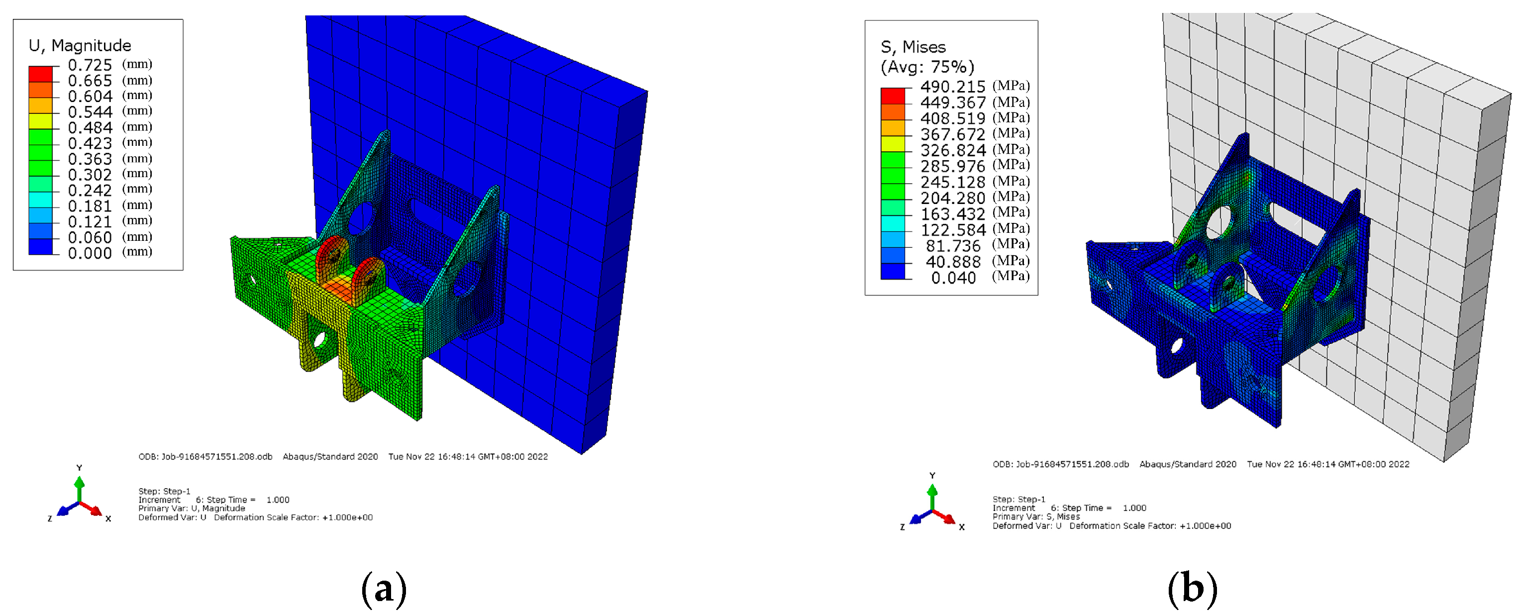
The finite element results of the wall-attached support are shown in Figure 9. The maximum composite deformation of 0.725 mm appeared at the top bracing side plate, and the maximum stress of 490.2 MPa at the intersection of the bottom and the side plate, meeting the requirement of the code (490.2 MPa < 510 MPa) [30].

Figure 9.
Finite element analysis results of wall-attached support model. (a) Composite deformation diagram. (b) Stress diagram.
4.4.2. Verifying Estimation of Bolt Strength at Connection between Wall-Attached Support and Main Structure
The wall-attached support transfers force to the wall through M30-specification bolts. In the model, the bolts were equivalently simulated utilizing constraints. Hence, it is necessary to check the strength of the bolts.
The wall-attached support was mainly subjected to vertical ( = N) and transverse forces ( = N). The bolting strength should be verified according to Equation (3) [30]:
where and represent the design value of shear force resisted and shear bearing capacity of a bolt, respectively; and indicate the design value of tension force resisted and tension bearing capacity of a bolt, respectively. After calculation, Equation (3) is 0.68. Therefore, the bolt strength of the wall-attached support meets the specification requirement.
4.4.3. Verifying Estimation of Concrete Strength at Connection between Wall-Attached Support and Main Structure
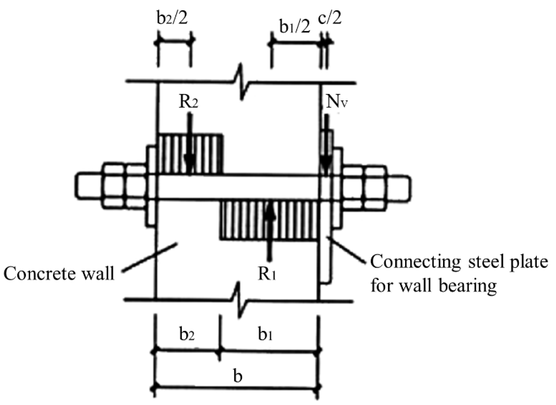
According to the technical code for the safety of implementation scaffold practice in construction [30], the compression of concrete at the through-wall bolt hole is shown in Figure 10. The bearing capacity of concrete at bolted joints should be satisfied by Equation (4):
where βb refers the load calculation coefficient of concrete in a bolt-hole = 0.39; means the improvement coefficient of local compressive strength of concrete = 1.73; denotes the design value of axial compressive strength of concrete = 9.6 N/mm2; is the thickness of the concrete of exterior wall = 200 mm; indicates the diameter of the bolt through the wall = 30 mm. Thus, Equation (4) is . Therefore, concrete strength at the connection between the wall-attached support and the main structure also satisfies the criteria of the specification.
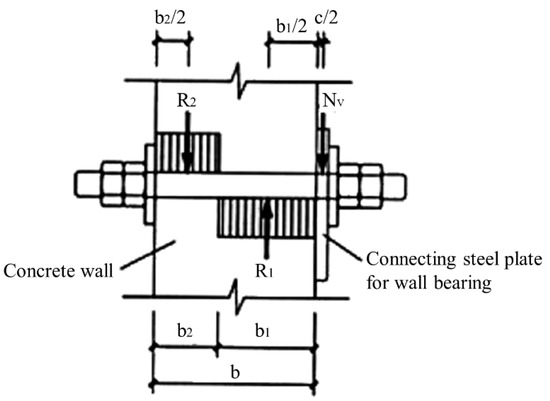
Figure 10.
Compression of concrete at the hole of bolt through the wall.
5. Key Parameters Analysis on Deformation of Novel Sorbite Stainless Steel-Aluminum Alloy Attached Lifting Protection Platform
According to several prior works, the mechanical performance of this structure is affected by three prominent aspects: the cantilever height of the protection platform, the horizontal spacing between two wall-attached supports, and the sectional size of the main frame fittings. Therefore, Midas GEN 2019 was utilized to construct finite element models for deformation analysis (the displacement of the main frame in the wind load direction (Y-direction)) under each parameter to explore the law of structural optimization.
5.1. Influence of Cantilever Height of Protection Platform on Deformation
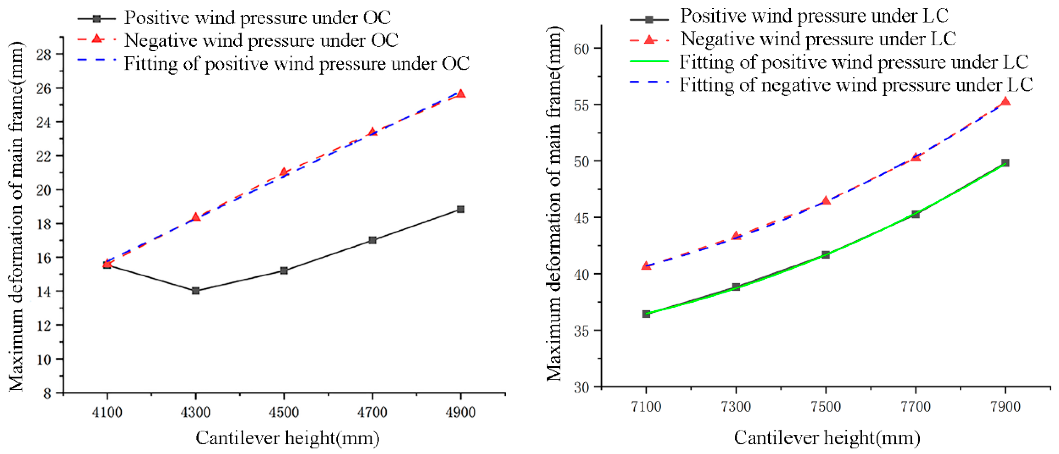
Table 11 summarizes the findings of the finite element model results of various cantilever heights, with positive and negative displacement values representing the deformation direction. To render the numerical changes more comprehensible, the absolute value of the displacement was graphed, and data that matched the functional relationship were fitted (Figure 11). Manifestly, the maximum deformation of the main frame is proportional to the cantilever height. However, due to the slight difference between the upper and lower cantilever portions, the descending segment occurs when this structure works under the operating condition with positive wind pressure. After fitting calculation, the slope under the operating condition with negative wind pressure is 0.0125, Indicating that the deformation rises by 1.25 mm for every 100 mm increase in the cantilever height. Under the lifting condition, the curve accords with the trend of multiple functions. The fitting results under the effect of positive wind pressure are shown in Table 12. The maximum deformation of the main frame varies considerably as the cantilever height increases. Among them, the quadratic coefficient of negative wind pressure under lifting condition can reach 9.52. Moreover, it can be seen that the structural deformation is more pronounced under negative wind pressure because self-weight causes the upper section of the structure to deform in the opposite direction of the wind. However, when the lengths of the upper and lower cantilever sections are relatively similar, the upper deformation under negative wind pressure may deviate negligibly from that under positive wind pressure.
Table 11.
Summary of deformation affected by cantilever height of protection platform.
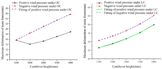
Figure 11.
Maximum deformation and corresponding fitting of main frame under cantilever height of protection platform variation. OC and LC is the operating and lifting condition.
Table 12.
Parameters of fitting curves under lifting condition with cantilever height of protection platform variation.
5.2. Influence of Horizontal Spacing between Two Wall-Attached Supports on Deformation
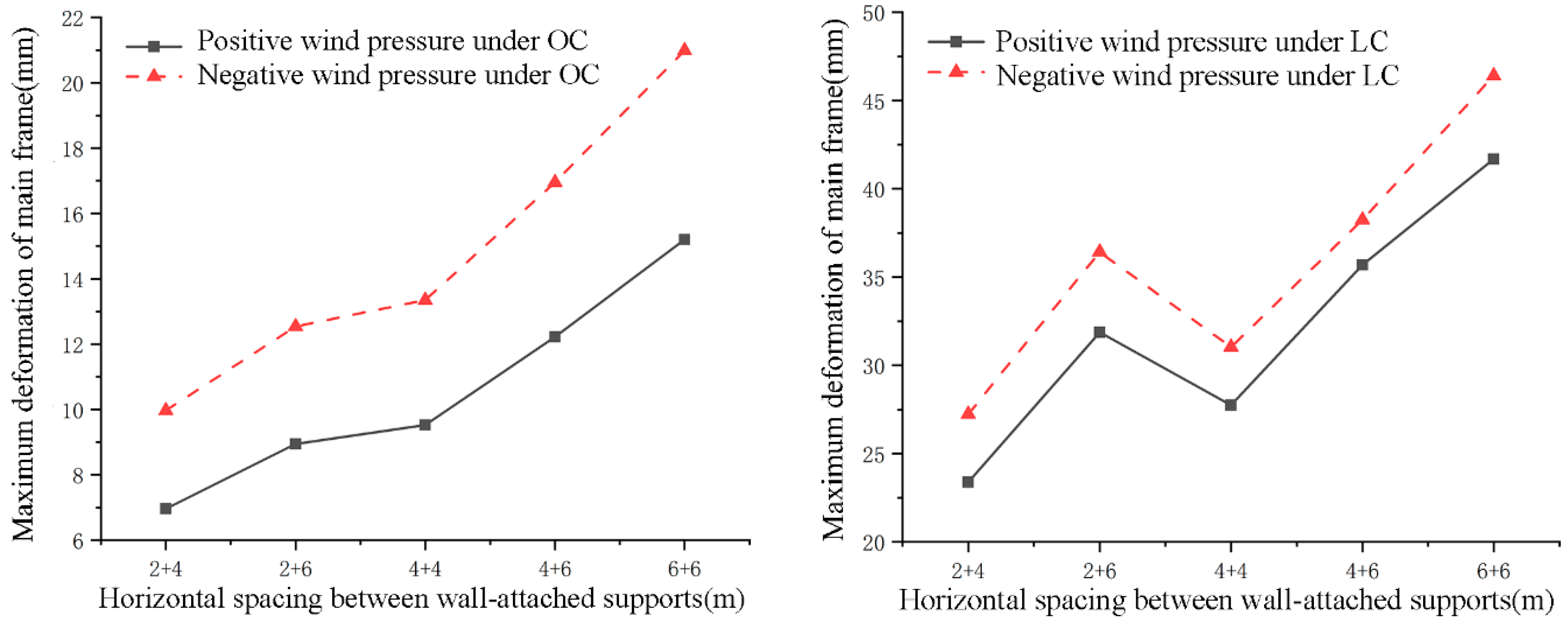
The finite element model results for various horizontal spacings between two wall-attached supports are shown in Table 13 and Figure 12. Under four service conditions with the same spacing on one side (2 + 4, 4 + 4, 4 + 6 vs. 2 + 6, 4 + 6, 6 + 6), the maximum deformation of the main frame rises with the spacing on the other side. Additionally, as the overall spacing grows, so does the deformation of the main frame. Interestingly, the uniform layout spacing (4 + 4 vs. 2 + 6) can lessen deformation when the entire spacing is the same. Moreover, the rate of change is lower under operating conditions than under lifting conditions. According to Table 13, the maximum slope of the lifting condition is 2.27 times that of the operating condition. Therefore, when this structure is used in the project, the wall-attached support should be distributed as evenly as feasible, and the structural measures should be reinforced under lifting condition.
Table 13.
Summary of deformation affected by horizontal spacing between two wall-attached supports.

Figure 12.
Maximum deformation of main frame under horizontal spacing between two wall-attached supports variation.
5.3. Influence of Cross-Sectional Size of Main Frame Fittings on Deformation
According to several earlier works on the all-steel attached lifting protection platform, the cross-sectional size of the main frame fittings has the most apparent effect on the mechanical performance of the structure and is regulated primarily by the guide rail. Therefore, the sectional sizes of the channel steel and the vertical bar of the guide rail were used as parameters. Since the influence of wall thickness on the mechanical characteristics of the protection platform is generally tiny, the wall thickness of the latter stays fixed, while the cross-sectional height in the wind load direction is primarily varied.
5.3.1. Influence of Type of Channel Steel of Guide Rail on Deformation
Table 14 and Figure 13 depict the findings of finite element models of multiple channel steel types of the guide rail (the material is still stainless steel, but the cross-section varies). Under four service conditions, the maximum deformation of the main frame falls as the type of channel steel grows, with the most significant reduction under the lifting condition. When upgrading the channel steel by one, the maximum deformation lowers by 6.45 mm. Consequently, the sectional size of channel steel significantly affects the deformation of the main frame.
Table 14.
Summary of deformation affected by channel steel type of guide rail.
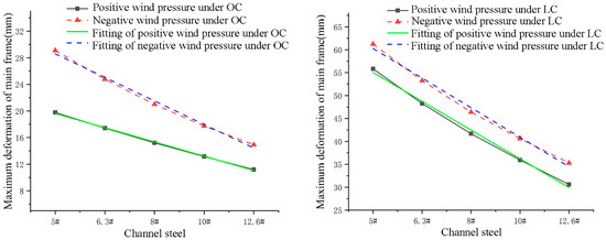
Figure 13.
Maximum deformation and corresponding fitting of main frame under channel steel type variation.
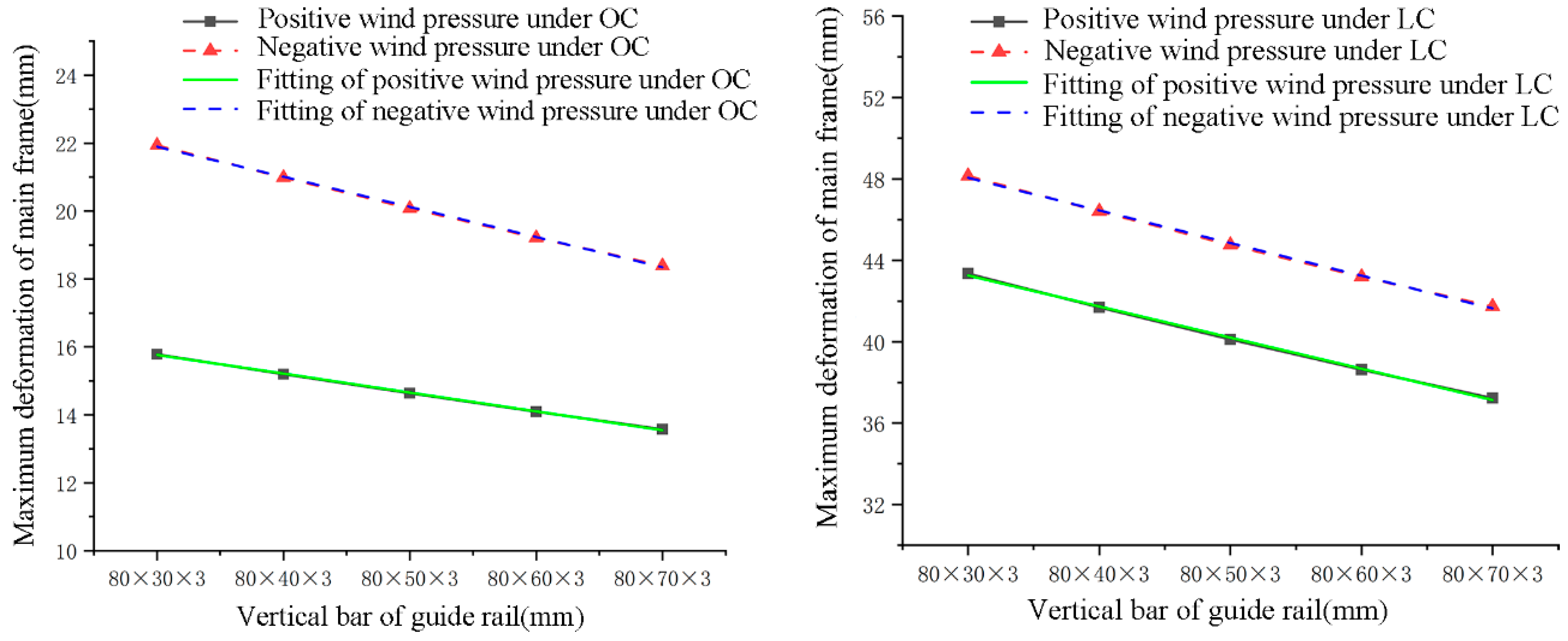
5.3.2. Influence of Sectional Size of Vertical Bar of Guideway Rail on Deformation
Table 15 and Figure 14 display the finite element model results of the vertical bar of guide rail variation. The maximum deformation of the main frame falls linearly as the sectional size grows, but the range of variation is low (decreases by 1.61 mm with an increase of 10 mm), presenting the largest value under lifting condition with negative wind pressure.
Table 15.
Summary of deformation affected by vertical bar section of guide rail variation.
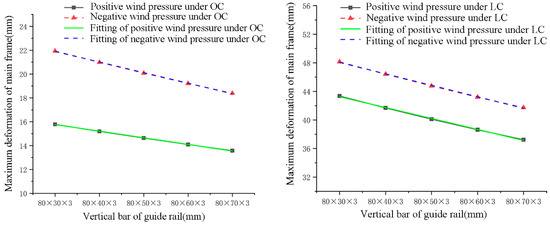
Figure 14.
Maximum deformation and corresponding fitting of main frame under vertical bar section of guide rail variation.
6. Comparison of Economic Benefits
From the above analysis, it is clear that the novel stainless steel-aluminum alloy protection platform adopts a similar section shape, loading mode, and boundary conditions to the all-steel protection platform, ensuring structural safety. Therefore, the former can structurally replace the latter. Nonetheless, stainless steel and aluminum alloy are frequently more expensive per unit than steel. This must be compared to the cost of an all-steel protection platform to evaluate whether potential utilization as potential materials and if they can be extensively implemented in actual manufacturing.
For this reason, the market was thoroughly investigated, and the relevant findings were derived by calculation. The price per ton of sorbite stainless steel is comparable to that of aluminum. Additionally, the anticipated manufacturing cost per unit weight of the stainless steel-aluminum alloy protection platform is almost double that of the platform made entirely of steel. So, when the mass of the stainless steel-aluminum alloy protection platform per extension meter is approximately half that of the all-steel protection platform, replacement is reasonable in the cost view.
The three-position vertical reaction force under the action of dead weight was retrieved using the finite element model of the novel stainless steel-aluminum alloy protection platform and the all-steel protection platform (Figure 15). As indicated in Table 16, the mass per extension meter of the two protection platforms can be assessed after calculating the total reaction forces of all the supports. Clearly, the entire mass of the stainless steel-aluminum alloy protection platform is less than half that of the all-steel structure. Thus, their cost is comparable. However, the corrosion resistance of stainless steel and aluminum alloy is far more excellent than that of conventional steel structures. Its reuse rate (300–500 times in standardized construction projects) is significantly higher than steel (30–40 times). Furthermore, the primary material of the novel stainless steel and aluminum alloy protection platform is aluminum alloy, whose residual value is much more than that of standard steel. Thereby, the materials using stainless steel and aluminum alloy as attached lifting protection platforms have considerable advantages in terms of long-term net gains, and this is a route that should be pursued in the future.
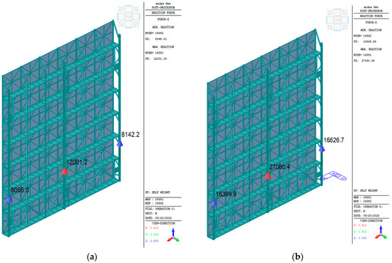
Figure 15.
Vertical reaction force of two protection platforms under dead weight. (a) stainless steel-aluminum alloy protection platform. (b) all-steel protection platform.
Table 16.
Comparison of mass per extension meter between stainless steel-aluminum alloy and all-steel protection platform.
7. Conclusions
In this study, the finite element model was validated by the test data of the all-steel attached lifting protection platform, and it was then utilized to compute the overall deformation of the novel sorbite stainless steel-aluminum alloy attached lifting protection platform. Meanwhile, the deformation of the wall-attached support was simulated using Abaqus to explore the stiffness of exact nodes. Additionally, the effects of the cantilever height of the protection platform, the horizontal spacing between two wall-attached supports, and the sectional size of the main frame fittings on the overall deformation and the economic benefits of the proposed structure were evaluated. The following are the primary findings:
- (1)
- Deformation of the novel sorbite stainless steel-aluminum alloy attached lifting protection platform in all directions under operating and lifting conditions with positive and negative wind pressure is less than 70% limitation of the “Code for Design of Aluminum Alloy structures”. Among these, the Y-direction deformation under the lifting condition with negative wind pressure reaches 76.9%. The maximum composite deformation of the wall-attached support is 0.725 mm, and the highest stress (490.2 MPa < 510 MPa) appears at the intersection of the bottom and the side plate, satisfying the code requirements and maintaining structural safety.
- (2)
- Maximum deformation of the main frame correlates positively with the cantilever height. Under operating conditions with negative wind pressure, an increase of 100 mm in cantilever height causes a 1.25 mm increment in deformation. The maximum frame deformation reduces as the section height of the guide rail grows, but the range of variation is limited (1.61 mm vs. 10 mm), whose most significant value is under lifting condition with negative wind pressure. The quadratic coefficient of negative wind pressure under lifting conditions can reach 9.52.
- (3)
- When the support spacing on one side remains constant, the maximum deformation of the main frame rises when the support spacing on the other side is extended. When the whole spacing is fixed, uniform spacing helps decrease deformation. Moreover, the shifting trend under operation condition is less pronounced than under lifting condition. The maximum slope of the lifting condition is 2.27 times that of the operating condition.
- (4)
- With an increase in channel steel type of guide rail, the maximum deformation of the main frame falls (each type vs. 6.45 mm), and the decline is most apparent under lifting condition. Therefore, this is the most critical factor in structural optimization.
- (5)
- The raw cost and structural performance of all-steel and novel sorbite stainless steel-aluminum safety protection platforms are comparable. Nevertheless, the corrosion resistance of stainless steel and aluminum alloy is far more excellent than that of conventional steel. Therefore, the reuse rate of the former (300–500 times in standardized construction projects) is significantly higher than that of the latter (30–40 times), favorable for substantial long-term economic benefits.
Author Contributions
Conceptualization, J.X., J.Y. and Y.H.; Methodology, J.X.; Validation, J.X. and Y.H.; Investigation, J.X.; Resources, J.Y.; Data curation, J.X. and Y.H.; Writing — original draft, J.X. and Y.H.; Writing — review & editing, J.X. and Y.H.; Visualization, J.X.; Supervision, J.Y., L.J. and J.Z.; Project administration, J.X. All authors have read and agreed to the published version of the manuscript.
Funding
The authors receive support from the Ministry of Housing and Urban-Rural Development of China for Technical specification for steel-concrete composite cavity floor structure (Construction standards [2013] No. 6-127).
Institutional Review Board Statement
Not applicable.
Informed Consent Statement
Not applicable.
Data Availability Statement
Not applicable.
Acknowledgments
The authors wish to acknowledge the National Engineering Laboratory’s technical support for High-Speed Railway Construction of the School of Civil Engineering, Central South University. Finally, and most importantly, the authors wish to thank the anonymous reviewers for their thorough evaluations and valuable comments, which have helped improve the paper.
Conflicts of Interest
The authors declare no conflict of interest.
References
- Yue, F.; Li, G.Q.; Yuan, Y. Design Methods of Integral-Lift Tubular Steel Scaffolds for High-Rise Building Construction. Struct. Des. Tall Spec. Build. 2012, 21, 46–56. [Google Scholar] [CrossRef]
- Liu, J.; Huang, H.; Ma, Z.J.; Chen, J. Effect of shear reinforcement corrosion on interface shear transfer between concretes cast at different times. Eng. Struct. 2021, 232, 111872. [Google Scholar] [CrossRef]
- Wang, Y.; Li, Q. Application of Aluminum Alloy Formwork in Some Super Tall Building. Constr. Technol. 2011, 40, 35–37,75. [Google Scholar]
- Liu, J. Application Foreground and ProductionState of Aluminium Alloy Large-Size Extrusion Materials. Light Alloy Fabr. Technol. 2005, 33, 8–11. [Google Scholar]
- GB/T 50429-2007; Code for Design of Aluminium Structures. Ministry of Construction of the People’s Republic of China: Beijing, China, 2007.
- Ma, X.; Zhang, C.; Zhang, Z. Microstructure and Properties of Sorbite Stainless Steel Designed by “Hybrid” Idea. Mater. Rep. 2020, 34, 103–107. [Google Scholar] [CrossRef]
- Zhong, C.; Shen, R.; Wang, H. Research on ultimate bearing capacity state and structure optimization of main cable saddle. Structures 2021, 33, 28–40. [Google Scholar] [CrossRef]
- Zheng, B.; Yang, S.; Jin, X.; Shu, G.; Dong, S.; Jiang, Q. Test on Residual Stress Distribution of Welded S600E High-Strength Stainless Steel Sections. J. Constr. Steel Res. 2020, 168, 105994. [Google Scholar] [CrossRef]
- Huang, Y.; Gan, V.J.L.; Chen, H.; Yang, J. Behavior of a two-way lightweight steel-concrete composite slab voided with thin-walled core boxes towards sustainable construction. Materials 2020, 13, 4129. [Google Scholar] [CrossRef] [PubMed]
- Sun, Z.; Niu, D.; Wang, X.; Zhang, L.; Luo, D. Bond behavior of coral aggregate concrete and corroded Cr alloy steel bar. J. Build. Eng. 2022, 61, 105294. [Google Scholar] [CrossRef]
- Chen, H.; Qin, R.; Lau, D. Recycling used engine oil in concrete design mix: An ecofriendly and feasible solution. J. Clean. Prod. 2021, 329, 129555. [Google Scholar] [CrossRef]
- PrEN1999-1-1:2002; Design of Aluminium Structures-General Structural Rules. CEN: Brussels, Belgium, 2002.
- Li, J. Theoretical and Experimental Study on Static Strength of Aluminum Alloy Structural Connection. Ph.D. Thesis, Tongji University, Shanghai, China, 2006. [Google Scholar]
- Guo, X.; Shen, Z.; Li, Y. Stress-Strain Relationship and Physical-Mechanical Properties of Domestic Structural Aluminum Alloy. J. Build. Struct. 2007, 28, 110–117. [Google Scholar]
- Yang, X. Stability Capacity Experimental Investigation and Numerical Analysis of H-Section High Strength Aluminum Alloy Beam-Columns. Master’s Thesis, Harbin Institute of Technology, Harbin, China, 2013. [Google Scholar]
- Huang, Y.; Yang, J.; Zhong, C. Flexural performance of assembly integral floor structure voided with steel mesh boxes. J. Build. Eng. 2022, 54, 104693. [Google Scholar] [CrossRef]
- Yang, J.; Chen, H.; Hu, S.; Gan, V.J.L. Experimental studies on the flexural behaviour of steel-concrete composite beams with transverse and longitudinal hidden girders. Eng. Struct. 2019, 179, 583–594. [Google Scholar] [CrossRef]
- Wang, H.; Du, W.; Zhao, Y.; Wang, Y.; Yang, M. Optimization and experimental research on treelike joints based on generative design and powder bed fusion. Eng. Struct. 2023, 278, 115564. [Google Scholar] [CrossRef]
- Macdonald, M.; Rhodes, J.; Taylor, G.T. Mechanical Properties of Stainless Steel Lipped Channels. In Proceedings of the International Specialty Conference on Cold-Formed Steel Structures, St. Louis, MO, USA, 19–20 October 2000; pp. 673–686. [Google Scholar]
- Rasmussen, K.J.R.; Burns, T.B.P. Design of Stiffened Elements in Cold-Formed Stainless Steel Sections. J. Struct. Eng. 2004, 130, 1764–1771. [Google Scholar] [CrossRef]
- Hradil, P.; Fülöp, L.T.A. Global Stability of Thin-Walled Ferritic Stainless Steel Members. Thin-Walled Struct. 2012, 61, 106–114. [Google Scholar] [CrossRef]
- Yuan, H. Local and Local-Overall Buckling Behaviour of Welded Stainless Steel Members under Axial Compression. Ph.D. Thesis, Tsinghua University, Beijing, China, 2014. [Google Scholar]
- Gardner, L.; Nethercot, D.A. Experiments on Stainless Steel Hollow Sections-Part 1: Material and Cross-Sectional Behaviour. J. Constr. Steel Res. 2004, 60, 1291–1318. [Google Scholar] [CrossRef]
- Zheng, B. Experimental Study on Material Properties of Stainless Steelat Room Temperature. Steel Constr. 2011, 26, 1–6+55. [Google Scholar]
- Zheng, B. Investigations on the Key Problems in the Mechanical Proper-Ties of Cold Formed Stainlesssteel Structures. Ph.D. Thesis, Southeast University, Nanjing, China, 2017. [Google Scholar]
- Quach, W.M.; Teng, J.G.; Chung, K.F. Three-Stage Full-Range Stress-Strain Model for Stainless Steels. J. Struct. Eng. 2008, 134, 1518–1527. [Google Scholar] [CrossRef]
- Huang, Y.; Yang, J.; Feng, R.; Chen, H. Resistance of Cold-Formed Sorbite Stainless Steel Circular Tubes under Uniaxial Compression. Thin-Walled Struct. 2022, 179, 109739. [Google Scholar] [CrossRef]
- Yu, W.K.; Chung, K.F.; Chan, S.L. Structural Instability of Multi-Storey Door-Type Modular Steel Scaffolds. Eng. Struct. 2004, 26, 867–881. [Google Scholar] [CrossRef]
- Zhang, H.; Rasmussen, K.J.R.; Ellingwood, B.R. Reliability Assessment of Steel Scaffold Shoring Structures for Concrete Formwork. Eng. Struct. 2012, 36, 81–89. [Google Scholar] [CrossRef]
- JGJ 202-2010; Technical Code for Safety of Implementation Scaffold Practice in Construction. Ministry of Housing and Urban-Rural Development of the People’s Republic of China: Beijing, China, 2010.
- JG/T 546-2019; Safety Protection Platform for Adhering Type Lifting Operation for Building Construction. Ministry of Housing and Urban-Rural Development of the People’s Republic of China: Beijing, China, 2019.
- Wu, X. Simulation Analysis of Aluminum Alloy Attached Lifting Scaffold in Engineering. Technol. Innov. Appl. 2022, 12, 32–36. [Google Scholar]
- Wang, Z.; Wang, Z. Application Research of Construction Mode Based on “Aluminum Mold + Climbing Frame” in Super High-Rise Building. Eng. Constr. 2022, 36, 1069–1071. [Google Scholar]
- DBJ 43/T375-2021; Safety Technical Specification for Attached Lifting Scaffolding in Hunan Province. Department of Housing and Urban-Rural Development of Hunan Province: Changsha, China, 2021.
- GB 50009-2012; Load Code for the Design of Building Structures. General Administration of Quality Supervision, Inspection and Quarantine of the PR China: Beijing, China; Ministry of Housing and Urban-Rural Development of the People’s Republic of China: Beijing, China, 2012.
- Guo, H.; Huang, C.; Li, H. Selection of Welding Materials for Sorbite Stainless Steel and 30CrMnSi Dissimilar Steel. Coal Mine Mach. 2019, 40, 104–106. [Google Scholar]
- Wang, P. Marine Tempered Sorbite High Strength and Toughness Stainless Structural Steel and Its Preparation Method. CN201910973471.3, 7 August 2019. [Google Scholar]
- Shi, Q. Production Process of Saustenite Strip Steel. CN110157883A, 23 August 2019. [Google Scholar]
- Li, Z. Applicationof Aluminum Alloy Latticed Shell Structure with Large Span. Eng. Constr. 2005, 37, 14–17. [Google Scholar]
- Ouyang, Y.; Qiu, L.; Li, Z. Application and Development Review of Large—Span Aluminum Alloy Structure. Build. Struct. 2018, 48, 1–7. [Google Scholar]
- He, Q.; Wang, X. Analysis of Application and Design Points of Aluminum Alloy Structure. Eng. Technol. Res. 2019, 4, 108–109. [Google Scholar] [CrossRef]
- Zhang, G.; Shi, Y.; Wang, Y. Analysis of Connection and Design Method of Aluminum Alloy Structure. Proc. Fifth Natl. Symp. Mod. Struct. Eng. 2005, 1429–1436. [Google Scholar]
- Liu, H.J.; Fujii, H.; Maeda, M.; Nogi, K. Tensile Properties and Fracture Locations of Friction-Stir Welded Joints of 6061-T6 Aluminum Alloy. J. Mater. Sci. Lett. 2003, 22, 1061–1063. [Google Scholar] [CrossRef]
- Shi, Y.; Cheng, M.; Wang, Y. Application and Research of Aluminum Alloy in Building Structure. Build. Sci. 2005, 21, 7–11. [Google Scholar]
- Özkılıç, Y.O. Interaction of Flange and Web Slenderness, Overstrength Factor and Proposed Stiffener Arrangements for Long Links. J. Constr. Steel Res. 2022, 190, 107150. [Google Scholar] [CrossRef]


Disclaimer/Publisher’s Note: The statements, opinions and data contained in all publications are solely those of the individual author(s) and contributor(s) and not of MDPI and/or the editor(s). MDPI and/or the editor(s) disclaim responsibility for any injury to people or property resulting from any ideas, methods, instructions or products referred to in the content. |
© 2023 by the authors. Licensee MDPI, Basel, Switzerland. This article is an open access article distributed under the terms and conditions of the Creative Commons Attribution (CC BY) license (https://creativecommons.org/licenses/by/4.0/).