Article

Dynamic Analysis of a Concrete-Cored Deep Cement Mixing Pile under Horizontal Dynamic Loads

1
Nantong Yanglv Railway Development and Construction Co., Ltd., Nantong 226601, China
2
School of Civil Engineering, Southeast University, Nanjing 211189, China
3
Jiangsu Hengtang Construction Technology Co., Ltd., Nantong 226400, China
*
Author to whom correspondence should be addressed.
Buildings 2023, 13(6), 1378; https://doi.org/10.3390/buildings13061378
Submission received: 30 April 2023 / Revised: 23 May 2023 / Accepted: 24 May 2023 / Published: 26 May 2023
(This article belongs to the Topic Advances on Structural Engineering, 2nd Volume)

Abstract

:
Concrete-cored deep cement mixing (DCM) pile is a novel type of pile foundation, and its lateral dynamic response analysis has great practical significance. Based on the elastic dynamic theory, this study investigated the lateral dynamic response of a concrete-cored DCM pile in the single-phase viscoelastic soil using theoretical deduction and parametric analysis. Considering the special structure of the concrete-cored DCM pile, the lateral vibration equation of the concrete-cored DCM pile is first established with mechanical equilibrium, and then the dynamic behavior of the soil around the pile is described using the existing governing equations of single-phase soils. Subsequently, the solutions for the dynamic impedances at the pile top are deduced after a series of rigorous theoretical derivations. Finally, the influence of the pile and soil parameters on the dynamic impedances at the pile top is studied using calculation examples and parameter analysis. The results reveal that the radius of the concrete-cored DCM pile obviously affects the dynamic impedances at the pile top. Enhancing the elastic modulus of the concrete-cored DCM pile is beneficial for augmenting the dynamic impedances at the pile top. An improvement in the soil density will increase the stiffness factors of the dynamic impedances at the pile top but will reduce their damping factors.

1. Introduction

In recent years, a new type of pile foundation has emerged and has been widely adopted in engineering applications, namely, concrete-cored deep cement mixing (DCM) piles. The concrete-cored DCM pile is a type of composite pile that combines a DCM pile (flexible pile) and a concrete-cored pile (rigid pile), and thus its inner and outer piles have complementary and enhancement effects on each other. Given the excellent load-bearing state of the concrete-cored DCM pile, conducting reasonable and in-depth theoretical research to further reveal its physical and mechanical characteristics is crucial for its engineering design.
Reviewing relevant works, we can find that most of the research on concrete-cored DCM piles currently focuses on their static mechanical behaviors. Bergado et al. [1] compared the static response of the concrete-cored DCM pile and DCM pile with experimental investigation and numerical simulation and revealed that the settlement and lateral displacement of the concrete-cored DCM pile were significantly lower than those of the DCM pile. Voottipruex et al. [2,3] studied the ultimate lateral load capacity of the concrete-cored DCM pile by performing full-scale pile load and embankment load tests and 3D finite element simulations. Although Bergado et al. [1] and Voottipruex et al. [2,3] presented good experimental and numerical results, further theoretical research is still needed. Hence, many researchers have conducted theoretical analyses on concrete-cored DCM piles from different perspectives. Wang et al. [4,5] proposed an analytical method of studying the vertical and lateral responses of the concrete-cored DCM pile using numerical and theoretical methods. This analytical method provided a theoretical basis for the vertical and lateral static calculations of concrete-cored DCM piles. Yu et al. [6] investigated the settlement behavior of composite foundations with concrete-cored DCM piles under rigid foundations with theoretical deduction. Zhang et al. [7] proposed an analytical solution for the consolidation of the composite ground reinforced by concrete-cored DCM pile based on a modified equal strain assumption. Han et al. [8] performed several model tests to study the vertical bearing capacity of concrete-cored DCM piles with different cement contents and observed two failure modes of concrete-cored DCM piles. Although the above calculation methods provide a theoretical basis for various static analyses of concrete-cored DCM piles, they are not yet applicable to their complex dynamic analysis. On the other hand, for the seismic behaviors of concrete-cored DCM piles, perhaps Wang et al. [9] and Zhang et al. [10] were the first to study the seismic responses of concrete-cored DCM piles using shaking table tests and numerical simulations. However, there are still no reports on dynamic calculation methods of concrete-cored DCM piles.
Overall, the current research on the mechanical characteristics of concrete-cored DCM piles is relatively complete in statics research, whereas dynamic analysis still needs further in-depth exploration. In addition, because of the horizontal dynamic loads such as train and wind loads, establishing an effective analysis approach for the lateral dynamic response of concrete-cored DCM piles is of great significance for the related engineering design. The analytical methods for pile dynamics are currently relatively complete. From the perspective of pile–soil interaction models, dynamic pile–soil interaction models mainly include three types: the Winkler model [11,12,13,14,15,16,17,18], the plane strain model [19,20,21], and the continuous medium model [22,23,24]. The continuous medium model obtained high-accuracy calculation results due to its rigorous analytical process. On the basis of the continuous medium model, the current study on the lateral dynamic response of single piles has been quite abundant [25,26,27,28,29,30,31,32], providing a strong foundation for conducting research on the lateral dynamic response of concrete-cored DCM piles.
In view of the above, the present work considers a concrete-cored DCM pile composed of a DCM pile and a concrete-cored pile, and regards the soil around the concrete-cored DCM pile as a single-phase viscoelastic medium. In addition, an analytical model is proposed to investigate the lateral dynamic behavior of the concrete-cored DCM pile embedded in a single-phase viscoelastic ground subjected to horizontal dynamic loads at the pile head. In the analytical model, the existing motion equations are employed to describe the dynamic behavior of soil around the concrete-cored DCM pile, and the Timoshenko beam theory is utilized to describe the lateral dynamic behavior of both the DCM pile and the concrete-cored pile. Subsequently, the closed-series form solution of the concrete-cored DCM pile–soil system is deduced theoretically. Finally, the effects of the physical parameters in the concrete-cored DCM pile–soil system on the lateral dynamic response of the concrete-cored DCM pile are evaluated using calculation examples and parametric analysis, which can provide references for related engineering design.

2. Physical Model and Basic Equations

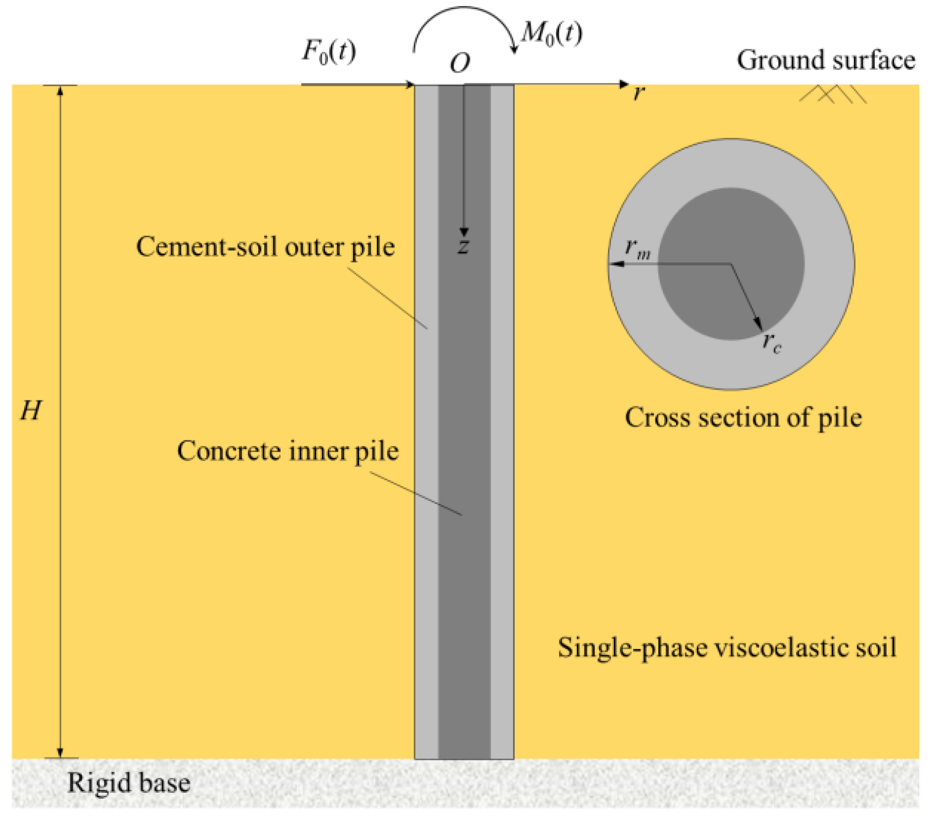
2.1. Physical Model of the Pile–Soil System

The interaction scheme of the concrete-cored DCM pile–soil system is portrayed in Figure 1. The concrete-cored DCM pile is composed of a concrete inner pile and a cement–soil outer pile. The concrete inner pile is the precast high-strength concrete solid pile and the cement–soil outer pile is the deep cement mixing pile. The interface between the concrete inner pile and the cement–soil outer pile has extremely high adhesion, and thus the inner and outer piles will not exhibit dislocation and debonding at the interface under the condition of meeting small deformation. The soil around the pile is single-phase viscoelastic soil. H is the length of the concrete-cored DCM pile. F0(t) and M0(t) are the lateral force and moment acting on the pile top of the concrete-cored DCM pile, respectively. rc and rm are the radii of the concrete inner pile and cement–soil outer pile, respectively.

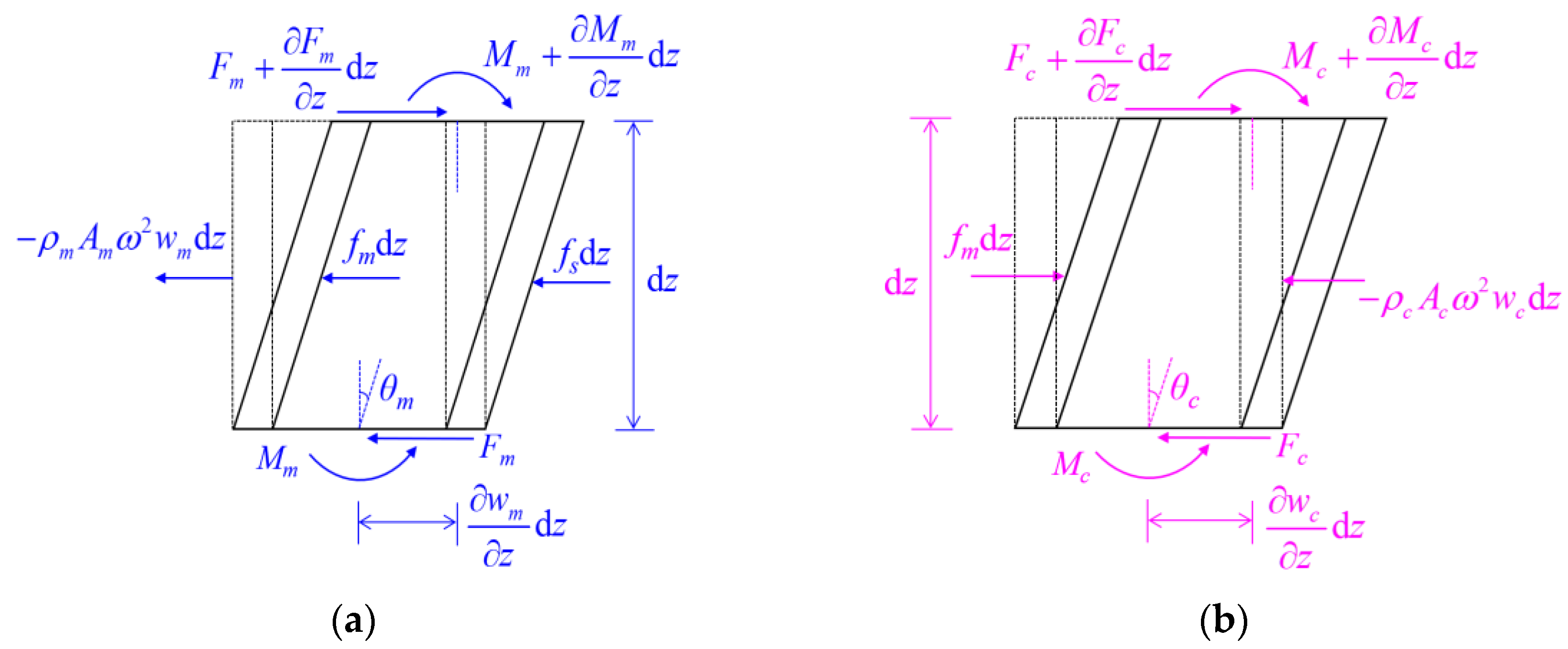
2.2. Basic Equations of the Pile–Soil System

The force analysis is carried out on the concrete-cored DCM pile element with unit height dz at depth z, as shown in Figure 2. Figure 2a illustrates the representative element of the cement–soil outer pile, where Fm and Mm represent the shear force and bending moment acting on both ends of the representative element, respectively; wm and θm are the lateral displacement and rotation angle of the cement–soil outer pile, respectively; ρm and Am are the density and cross-sectional area of the cement–soil outer pile, respectively; and fs and fm are the lateral resistances contributed by the soil formed around the pile and concrete inner pile, respectively. Figure 2b presents the representative element of the concrete inner pile, where Fc and Mc are the shear force and bending moment acting on both ends of the representative element, respectively; ρc and Ac are the density and cross-sectional area of the concrete inner pile, respectively; and wc and θc are the lateral displacement and rotation angle of the concrete inner pile, respectively. ω = 2πf represents the circular frequency with f as the frequency.
Applying moment balance to the upper boundary midpoint of the cement–soil outer pile element yields
F m d z + M m z d z + 1 2 f m + f s d z 2 = ρ m I m ω 2 θ m d z
Omitting the second-order differential term in Equation (1) yields
F m + M m z + ρ m I m ω 2 θ m = 0
Applying D’ Alembert principle to the horizontal direction of the cement–soil outer pile element, the following formula can be yielded:
F m z f m f s = ρ m A m ω 2 w m
In the same way, the balance equations of concrete inner pile elements are expressed as
F c + M c z + ρ c I c ω 2 θ c = 0
F c z + f m = ρ c A c ω 2 w c
According to Timoshenko beam theory, the relationships between the bending moment (shear force) and lateral displacement (rotation angle) of the concrete inner pile and cement–soil outer pile are
M m = E m I m θ m z ,   F m = A m G m K m w m z θ m M c = E c I c θ c z ,   F c = A c G c K c w c z θ c
with K m = 6 1 + ν m 1 + r c / r m 2 2 7 + 6 ν m 1 + r c / r m 2 2 + 20 + 12 ν m r c / r m 2 , and K c = 6 1 + ν c 7 + 6 ν m , where Ec and Em are the elastic modulus of the concrete inner pile and cement–soil outer pile, respectively; Ic and Im are the moment of inertia of the cross-section of the concrete inner pile and cement–soil outer pile, respectively; Gc and Gm are the shear modulus of the concrete inner pile and cement–soil outer pile, respectively; νc and νm are the Poisson’s ratio of the concrete inner pile and cement–soil outer pile, respectively; and Kc and Km the shear correction factor of the concrete inner pile and cement–soil outer pile, respectively.
Since the hypothesis of small deformation is considered in this work, and a high adhesion exists at the interface between the concrete inner pile and the cement–soil outer pile, the lateral displacement and rotation angle of the concrete inner pile and cement–soil outer pile can be uniformly expressed as
w p = w m = w c θ p = θ m = θ c
Combining Equations (2)–(5) and considering Equations (6) and (7) generate
A m G m K m + A c G c K c w p z θ p + E m I m + E c I c 2 θ p z 2 + ρ m I m + ρ c I c ω 2 θ p = 0
A m G m K m + A c G c K c 2 w p z 2 θ p z + ρ m A m + ρ c A c ω 2 w p f s = 0
Combining Equations (8) and (9) yields
4 w p z 4 + H 1 2 w p z 2 + H 2 w p = H 4 2 z 2 + H 3 f s
4 θ p z 4 + H 1 2 θ p z 2 + H 2 θ p = H 5 f s z
with
H 1 = ρ m A m + ρ c A c ω 2 A m G m K m + A c G c K c + ρ m I m + ρ c I c ω 2 E m I m + E c I c ,
H 2 = ρ m I m + ρ c I c ρ m A m + ρ c A c ω 4 A m G m K m + A c G c K c E m I m + E c I c ρ m A m + ρ c A c ω 2 E m I m + E c I c ,
H 3 = ρ m I m + ρ c I c ω 2 A m G m K m + A c G c K c A m G m K m + A c G c K c E m I m + E c I c ,   H 4 = 1 A m G m K m + A c G c K c ,   H 5 = 1 E m I m + E c I c
According to the elastic dynamic theory, the governing equations of motion for the soil around the concrete-cored DCM pile can be expressed as
μ 2 1 r 2 u r + λ + μ ε s r μ 2 r 2 u θ θ + μ 2 u r z 2 = ρ s ω 2 u r
μ 2 1 r 2 u θ + λ + μ ε s r θ + μ 2 r 2 u r θ + μ 2 u θ z 2 = ρ s ω 2 u θ
where λ = λs(1 + 2iβs) and μ = μs(1 + 2iβs) denote the complex moduli of soil, with λs and μs as the Lamé constant of soil, and βs as the damping ratio of soil. ur, uθ, and uz denote the radial, circumferential, and vertical displacement of soil, respectively. ρs denotes the mass density of soil. ∇2 is the Laplace operator. εs is the volume strain of soil and can be expressed as
ε s = u r r + u r r + 1 r u θ θ

2.3. Boundary Conditions of the Pile–Soil System

The ground surface satisfies the free boundary condition, and thus
u r z z = 0 = u θ z z = 0 = 0
The bottom of the soil around the concrete-cored DCM pile is the fixed boundary, and thus
u r z = H = u θ z = H = 0
The radial and circumferential displacements of the soil around the concrete-cored DCM pile at the infinity are
u r r = u θ r = 0
The pile end of the concrete-cored DCM pile is assumed as the fixed boundary, that is,
w p z = H = 0 ,   θ p z = H = 0
It is assumed that the concrete-cored DCM pile and soil are in complete contact at their interface, and thus the interface meets as follows:
u r r = r m = w p cos θ ,   u θ r = r m = w p sin θ

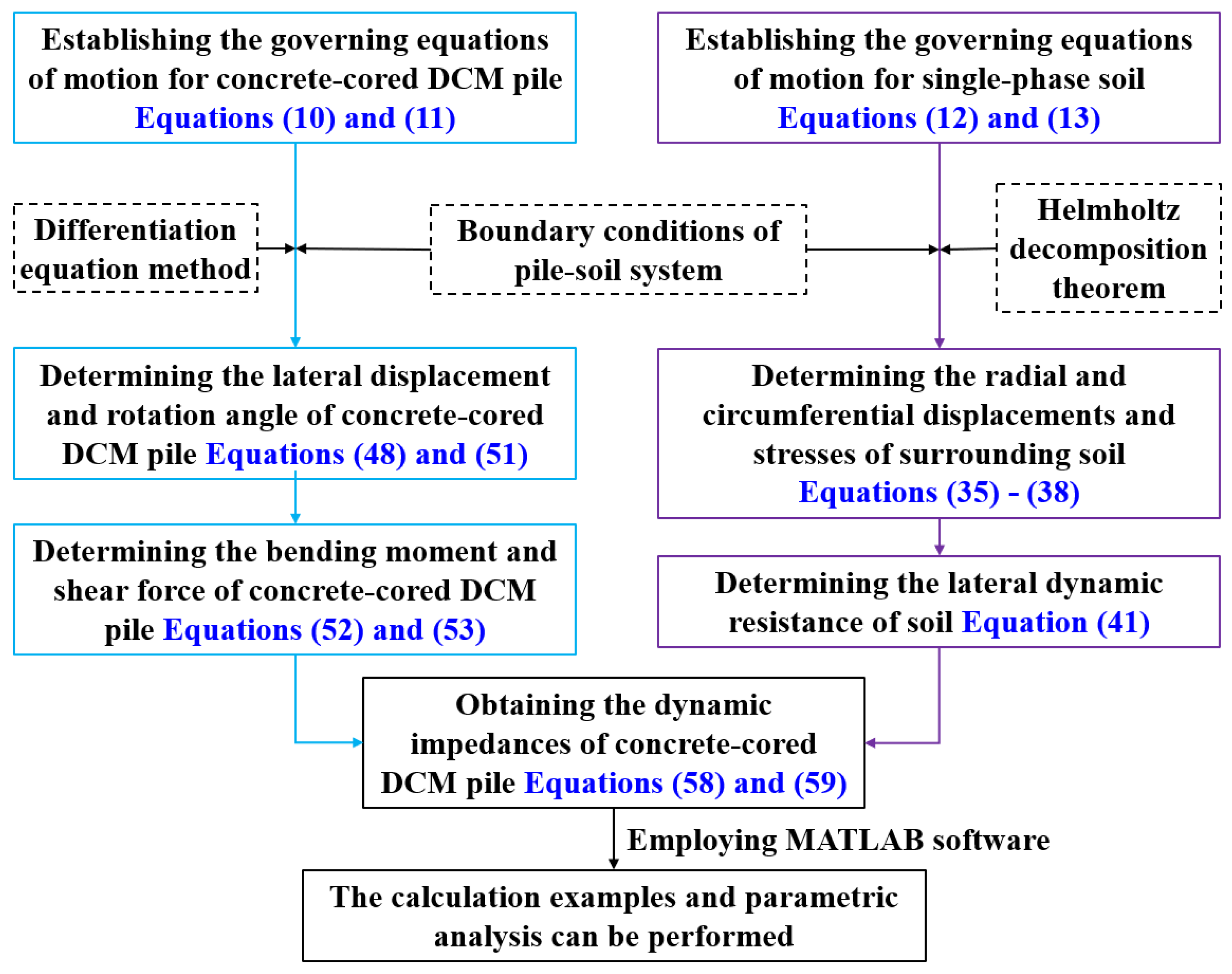
3. Solutions of the Pile–Soil System

3.1. Solution for the Surrounding Soil

According to the Helmholtz decomposition theorem, the radial and circumferential displacements of soil can be represented by potential functions, i.e.,
u r = φ s r + 1 r ψ s θ u θ = 1 r φ s θ ψ s r
where φs and ψs represent the scalar and vector potentials of soil displacement, respectively.
Substituting Equations (14) and (20) into Equations (12) and (13), it can be inferred that
λ + 2 μ 2 + ρ s ω 2 + μ 2 z 2 φ s = 0
μ 2 + ρ s ω 2 + μ 2 z 2 ψ s = 0
The scalar potential φs and vector potential ψs of soil displacement can be expressed as
φ s = φ s * r , θ Z z ψ s = ψ s * r , θ Z z
Let
1 Z z 2 Z z z 2 = g 2
According to the boundary conditions in Equations (15) and (16), the general solution of Z(z) can be obtained from Equation (24) as
Z z = F cosh g z
where F is the undetermined coefficient and g n = 2 n 1 π i / 2 H with n = 1 , 2 , 3 .
Therefore, Equations (21) and (22) can be further represented as
λ + 2 μ 2 + ρ s ω 2 + μ g n 2 φ s = 0
μ 2 + ρ s ω 2 + μ g n 2 ψ s = 0
By using the method of variable separation, the general solution of φs and ψs can be obtained by Equations (26) and (27), i.e.,
φ s = B 1 K m β 1 r + C 1 I m β 1 r D 1 sin m θ + E 1 cos m θ cosh g n z
ψ s = B 2 K m β 2 r + C 2 I m β 2 r D 2 sin m θ + E 2 cos m θ cosh g n z
where B1, B2, C1, C2, D1, D2, F1, and F2 are undetermined coefficients. Im(·) and Km(·) represent the first and second modified m-order Bessel functions, respectively, with m as the natural number. β 1 2 = ρ s ω 2 μ g n 2 / λ + 2 μ and β 2 2 = ρ s ω 2 μ g n 2 / μ .
The parity of the radial and circumferential displacement for the soil leads to D1 = E2 = 0, the boundary conditions in Equations (15)–(17) result in C1 = C2 = 0, and the boundary condition in Equation (19) generates m = 1. Therefore, the general solution of φs and ψs is further expressed as
φ s = B 1 K 1 β 1 r cos θ cosh g n z
ψ s = B 2 K 1 β 2 r sin θ cosh g n z
By substituting Equations (30) and (31) into Equation (20), we can obtain
u r = 1 2 n = 1 B 2 n β 2 n K 2 β 2 n r K 0 β 2 n r B 1 n β 1 n K 2 β 1 n r + K 0 β 1 n r cosh g n z cos θ
u θ = 1 2 n = 1 B 2 n β 2 n K 2 β 2 n r + K 0 β 2 n r B 1 n β 1 n K 2 β 1 n r K 0 β 1 n r cosh g n z sin θ
Based on the boundary condition in Equation (19), the derivation leads to
B 2 n = β 1 n K 2 β 1 n r m β 2 n K 2 β 2 n r m B 1 n
In summary, the radial and circumferential displacement of the soil around the concrete-cored DCM pile can be expressed as a closed-series form as follows:
u r = n = 1 ξ 1 n B 1 n cosh g n z cos θ
u θ = n = 1 ξ 2 n B 1 n cosh g n z sin θ
with
ξ 1 n = χ n β 2 n K 2 β 2 n r K 0 β 2 n r 2 β 1 n K 2 β 1 n r + K 0 β 1 n r 2 ,
ξ 2 n = χ n β 2 n K 2 β 2 n r + K 0 β 2 n r 2 β 1 n K 2 β 1 n r K 0 β 1 n r 2 ,   χ n = β 1 n K 2 β 1 n r m β 2 n K 2 β 2 n r m .
The normal and shear stresses of the soil around the concrete-cored DCM pile can be expressed as
σ r r = λ ε s + 2 μ u r r = n = 1 ς 1 n B 1 n cosh g n z cos θ
σ r θ = μ 1 r u r θ + u θ r u θ r = n = 1 ς 2 n B 1 n cosh g n z sin θ
with
ς 1 n = λ + 3 μ 2 β 1 n 2 K 1 β 1 n r + μ 2 β 1 n 2 K 3 β 1 n r + χ n β 2 n 2 K 1 β 2 n r K 3 β 2 n r
ς 2 n = μ 2 β 1 n 2 K 3 β 1 n r K 1 β 1 n r χ n β 2 n 2 K 3 β 2 n r + K 1 β 2 n r
Subsequently, the dynamic resistance of the soil to the lateral movement of the concrete-cored DCM pile can be expressed as
f s = r m 0 2 π σ r r cos θ σ r θ sin θ r = r m d θ = n = 1 ξ 3 n B 1 n cosh g n z
with ξ 3 n = π r m λ + 2 μ β 1 n 2 K 1 β 1 n r m + μ χ n β 2 n 2 K 1 β 2 n r m .

3.2. Solution for the Concrete-Cored DCM Pile

Substituting Equation (41) into Equations (10) and (11), it can be inferred that
4 w p z 4 + H 1 2 w p z 2 + H 2 w p = n = 1 H 3 + H 4 g n 2 ξ 3 n B 1 n cosh g n z
4 θ p z 4 + H 1 2 θ p z 2 + H 2 θ p = n = 1 H 5 g n ξ 3 n B 1 n sinh g n z
The solution of Equation (42) can be expressed as
w p = J 1 sin η 1 z + J 2 cos η 1 z + J 3 sinh η 2 z + J 4 cosh η 2 z + n = 1 ζ 1 n B 1 n cosh g n z
with
η 1 = 1 2 H 1 2 4 H 2 + H 1 ,   η 2 = 1 2 H 1 2 4 H 2 H 1 ,   and   ζ 1 n = H 3 + H 4 g n 2 ξ 3 n g n 4 + H 1 g n 2 + H 2 .
According to the first formula in Equation (19), u r r = r m = w p cos θ , we obtain
n = 1 ξ 1 n r = r m B 1 n cosh g n z = J 1 sin η 1 z + J 2 cos η 1 z + J 3 sinh η 2 z + J 4 cosh η 2 z + n = 1 ζ 1 n B 1 n cosh g n z
The hyperbolic cosine function has the following orthogonal properties:
0 H cosh g m z cosh g n z d z = H 2 ,   m = n 0 H cosh g m z cosh g n z d z = 0 ,   m n
Multiplying both ends of Equation (45) by cosh(gnz) and integrating within the interval (0, H), combined with the orthogonal properties of the hyperbolic cosine function in Equation (46), it can be derived that
B 1 n = 2 J 1 K 1 + J 2 K 2 + J 3 K 3 + J 4 K 4 H ξ 1 n r = r m ζ 1 n
with
K 1 = 0 H sin η 1 z cosh g n z d z ,   K 2 = 0 H cos η 1 z cosh g n z d z ,
K 3 = 0 H sinh η 2 z cosh g n z d z ,   and   K 4 = 0 H cosh η 2 z cosh g n z d z .
Substituting Equation (47) into Equation (44) obtains the lateral displacement wp of the concrete-cored DCM pile as
w p = J 1 sin η 1 z + n = 1 K 1 Φ 1 n cosh g n z + J 2 cos η 1 z + n = 1 K 2 Φ 1 n cosh g n z + J 3 sinh η 2 z + n = 1 K 3 Φ 1 n cosh g n z + J 4 cosh η 2 z + n = 1 K 4 Φ 1 n cosh g n z
with Φ 1 n = 2 ζ 1 n / H ξ 1 n r = r m ζ 1 n .
Similarly, the rotation angle θp of the concrete-cored DCM pile can be obtained from Equation (43) as
θ p = J 5 sin η 1 z + J 6 cos η 1 z + J 7 sinh η 2 z + J 8 cosh η 2 z + n = 1 ζ 2 n B 1 n sinh g n z
with ζ 2 n = H 5 g n ξ 3 n / g n 4 + H 1 g n 2 + H 2 .
Substituting Equations (48) and (49) into Equation (9), it can be inferred that
J 5 = ρ m A m + ρ c A c ω 2 A m G m K m + A c G c K c η 1 η 1 J 2 ,   J 6 = η 1 ρ m A m + ρ c A c ω 2 A m G m K m + A c G c K c η 1 J 1 J 7 = η 2 + ρ m A m + ρ c A c ω 2 A m G m K m + A c G c K c η 2 J 4 ,   J 8 = η 2 + ρ m A m + ρ c A c ω 2 A m G m K m + A c G c K c η 2 J 3
Substituting Equations (47) and (50) into Equation (49), it can be inferred that
θ p = J 1 n 1 cos η 1 z + n = 1 K 1 Φ 2 n sinh g n z + J 2 n 2 sin η 1 z + n = 1 K 2 Φ 2 n sinh g n z + J 3 n 3 cosh η 2 z + n = 1 K 3 Φ 2 n sinh g n z + J 4 n 4 sinh η 2 z + n = 1 K 4 Φ 2 n sinh g n z
with
Φ 2 n = 2 ζ 2 n H ξ 1 n r = r m ζ 1 n ,   n 1 = n 2 = η 1 ρ m A m + ρ c A c ω 2 A m G m K m + A c G c K c η 1 ,   and
n 3 = n 4 = η 2 + ρ m A m + ρ c A c ω 2 A m G m K m + A c G c K c η 2
According to the relationship between the bending moment Mp and shear force Fp of the concrete-cored DCM pile and its lateral displacement wp and rotation angle θp, it can be obtained that
M p E I = θ p z = J 1 n 1 η 1 sin η 1 z + n = 1 K 1 g n Φ 2 n cosh g n z + J 2 n 2 η 1 cos η 1 z + n = 1 K 2 g n Φ 2 n cosh g n z + J 3 n 3 η 2 sinh η 2 z + n = 1 K 3 g n Φ 2 n cosh g n z + J 4 n 4 η 2 cosh η 2 z + n = 1 K 4 g n Φ 2 n cosh g n z
F p A G K = w p z θ p = J 1 η 1 n 1 cos η 1 z + n = 1 K 1 g n Φ 1 n Φ 2 n sinh g n z + J 2 η 1 n 2 sin η 1 z + n = 1 K 2 g n Φ 1 n Φ 2 n sinh g n z + J 3 η 2 n 3 cosh η 2 z + n = 1 K 3 g n Φ 1 n Φ 2 n sinh g n z + J 4 η 2 n 4 sinh η 2 z + n = 1 K 4 g n Φ 1 n Φ 2 n sinh g n z
with EI = EmIm + EcIc and AGK = AmGmKm + AcGcKc.
Let the lateral displacement, rotation angle, bending moment, and shear force at the pile head of the concrete-cored DCM pile be w0, θ0, M0, and F0, respectively, i.e., z = 0 in Equations (48) and (51)–(53), and then we can obtain
n = 1 K 1 Φ 1 n 1 + n = 1 K 2 Φ 1 n n = 1 K 3 Φ 1 n 1 + n = 1 K 4 Φ 1 n n 1 0 n 3 0 n = 1 K 1 g n Φ 2 n n 2 η 1 + n = 1 K 2 g n Φ 2 n n = 1 K 3 g n Φ 2 n n 4 η 2 + n = 1 K 4 g n Φ 2 n η 1 n 1 0 η 2 n 3 0 J 1 J 2 J 3 J 4 = w 0 θ 0 M 0 E I F 0 A G K
It can be solved from Equation (54) that
J 1 = s 1 θ 0 + s 2 F 0 J 2 = s 3 w 0 + s 4 θ 0 + s 5 M 0 + s 6 F 0 J 3 = s 7 θ 0 + s 8 F 0 J 4 = s 9 w 0 + s 10 θ 0 + s 11 M 0 + s 12 F 0
where the expressions of s1~s12 are detailed in Appendix A.
Substituting Equation (55) into Equations (48) and (51), while considering the pile bottom boundary conditions shown in Equation (26), it can be obtained that
u 1 w 0 + u 2 θ 0 + u 3 M 0 + u 4 F 0 = 0 u 5 w 0 + u 6 θ 0 + u 7 M 0 + u 8 F 0 = 0
where the expressions of u1~u8 are detailed in Appendix B.
It can be obtained from Equation (56) that
F 0 = u 3 u 5 u 1 u 7 u 4 u 7 u 3 u 8 w 0 + u 3 u 6 u 2 u 7 u 4 u 7 u 3 u 8 θ 0 M 0 = u 4 u 5 u 1 u 8 u 3 u 8 u 4 u 7 w 0 + u 4 u 6 u 2 u 8 u 3 u 8 u 4 u 7 θ 0
The horizontal dynamic impedance Khh, rocking dynamic impedance Krr, and horizontal–rocking dynamic impedance Khr (Krh) of the concrete-cored DCM pile can be expressed as
K h h = u 3 u 5 u 1 u 7 u 4 u 7 u 3 u 8 ,   K r r = u 4 u 6 u 2 u 8 u 3 u 8 u 4 u 7 K h r = u 3 u 6 u 2 u 7 u 4 u 7 u 3 u 8 ,   K r h = u 4 u 5 u 1 u 8 u 3 u 8 u 4 u 7
Furthermore, the dimensionless forms of the three types of dynamic impedances mentioned above can be expressed as
k h h = Re K h h E c r c ,   k r r = Re K r r E c r c 3 ,   k h r = Re K h r E c r c 2 c h h = Im K h h E c r c ,   c r r = Im K r r E c r c 3 ,   c h r = Im K h r E c r c 2
where Re(·) and Im(·) represent the real and imaginary parts, respectively. khh, krr, and khr represent the dynamic stiffness factor of horizontal, rocking, and horizontal–rocking dynamic impedances, respectively. chh, crr, and chr represent the dynamic damping factor of horizontal, rocking, and horizontal–rocking dynamic impedances, respectively.

4. Calculation Results and Parametric Analysis
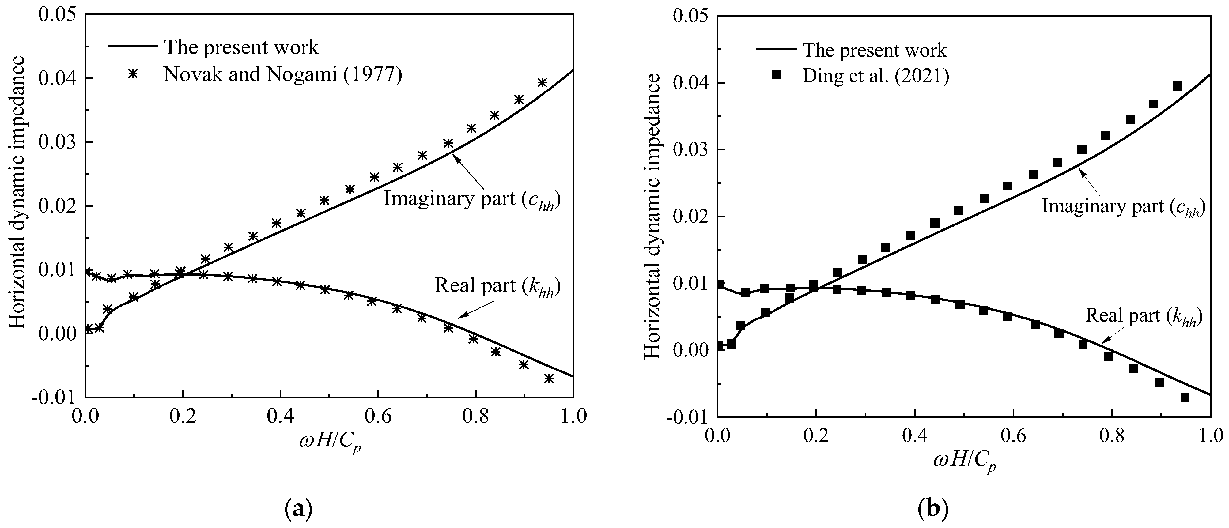
The dimensionless forms of the horizontal, rocking, and horizontal–rocking dynamic impedances can be obtained via a careful compilation of the above equations employing MATLAB software. To clearly illustrate the deductive process of the analytical solution of the model in this work, a solution flow chart is shown in Figure 3.

4.1. Verification

To verify the reasonability of the proposed mathematical model, this section sets the radius of the cement–soil outer pile equal to the radius of the concrete inner pile, and compares the calculation results in this work with the solutions developed by Novak and Nogami [27] and Ding et al. [33], respectively. The comparison curves are demonstrated in Figure 4 with C p = E c / ρ c as the wave velocity of a compression wave in the concrete inner pile, whereas Figure 4a is the comparison curve with Novak and Nogami [27] and Figure 4b is the comparison curve with Ding et al. [33]. It can be seen from Figure 4 that the calculation results in this work are qualitatively and quantitatively consistent with the results obtained by Novak and Nogami [27] and Ding et al. [33], respectively. The difference in magnitude between the results of this work and those of the existing literature does not exceed 5%, and thus the difference in magnitude is relatively small and within an acceptable range. In detail, this slight difference in magnitude is mainly due to the dynamic calculation of piles in this work employing the Timoshenko beam theory, whereas the Euler–Bernoulli beam theory was utilized by Novak and Nogami [27] and Ding et al. [33]. Consequently, slight differences of less than 5% in magnitude can be safely ignored in engineering applications.

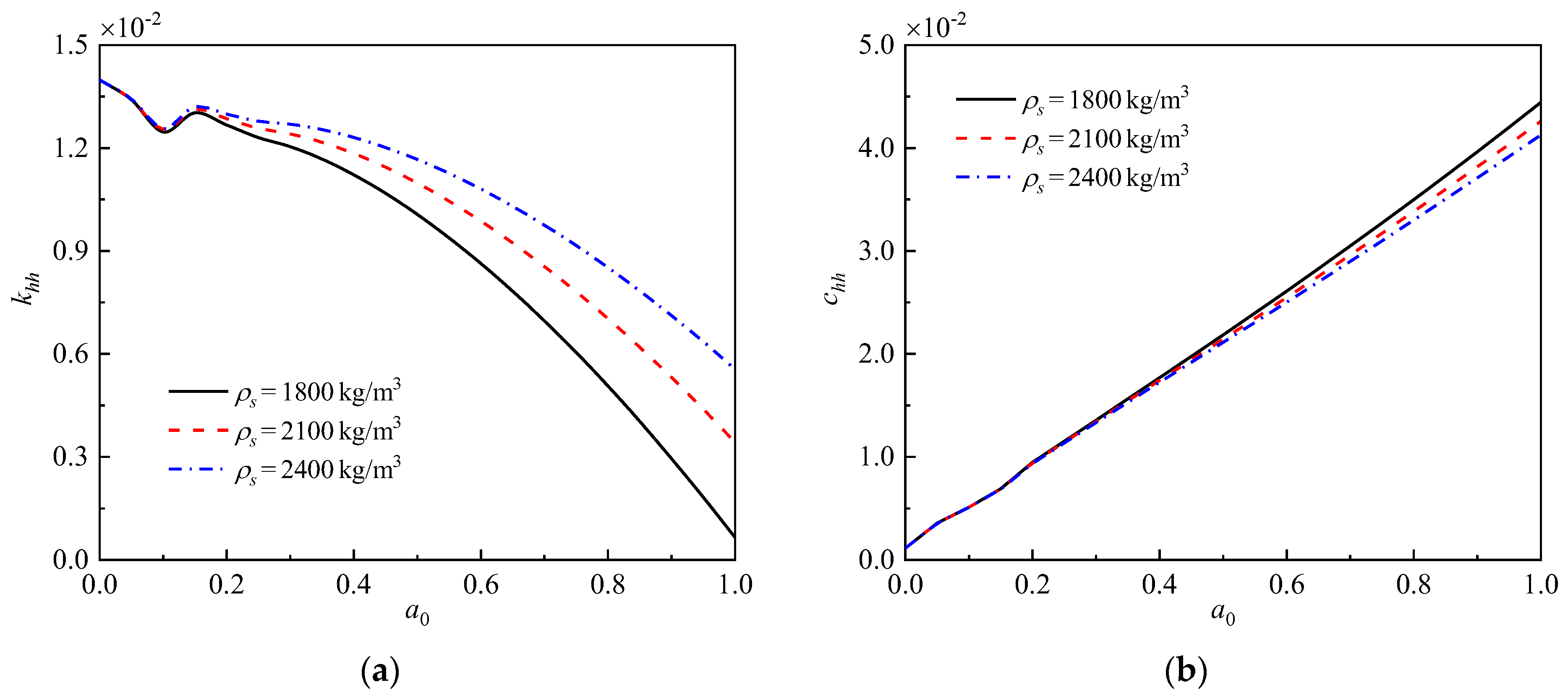
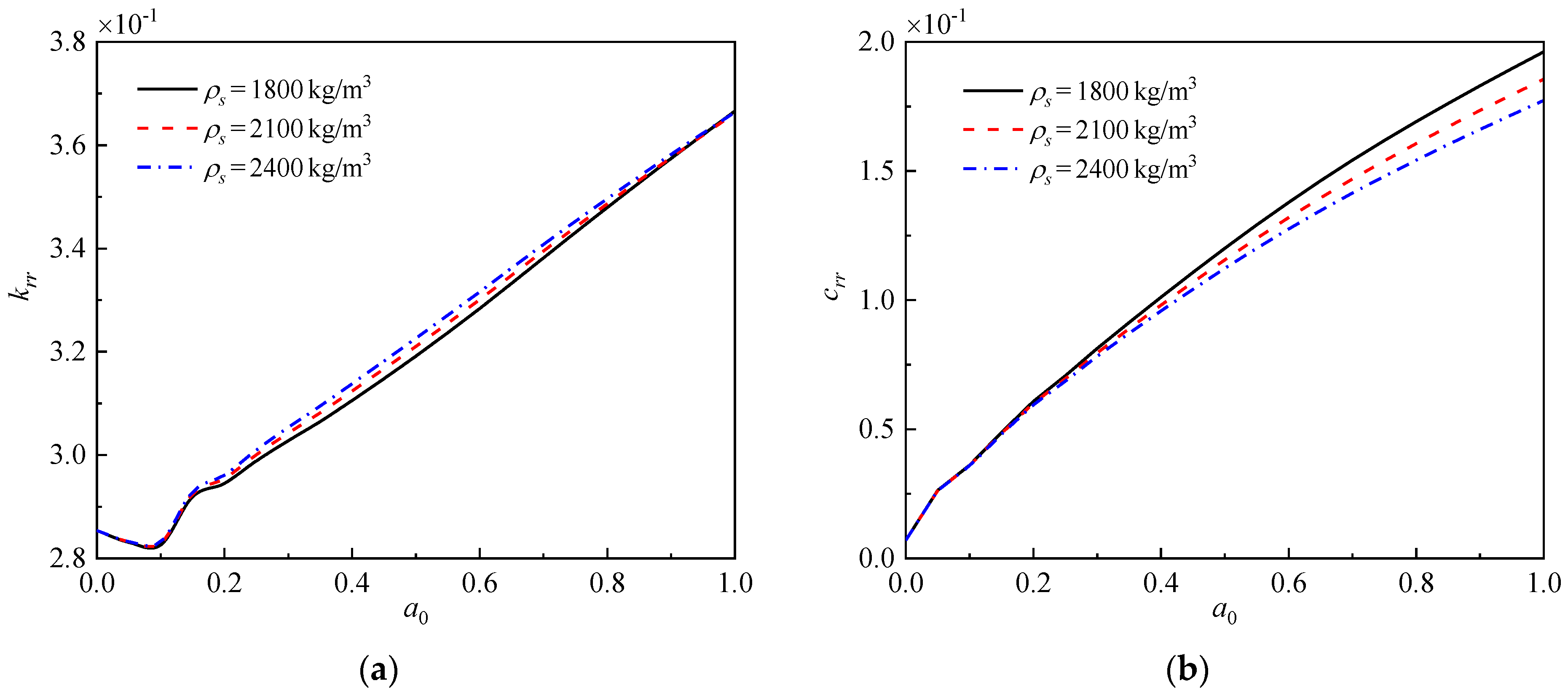
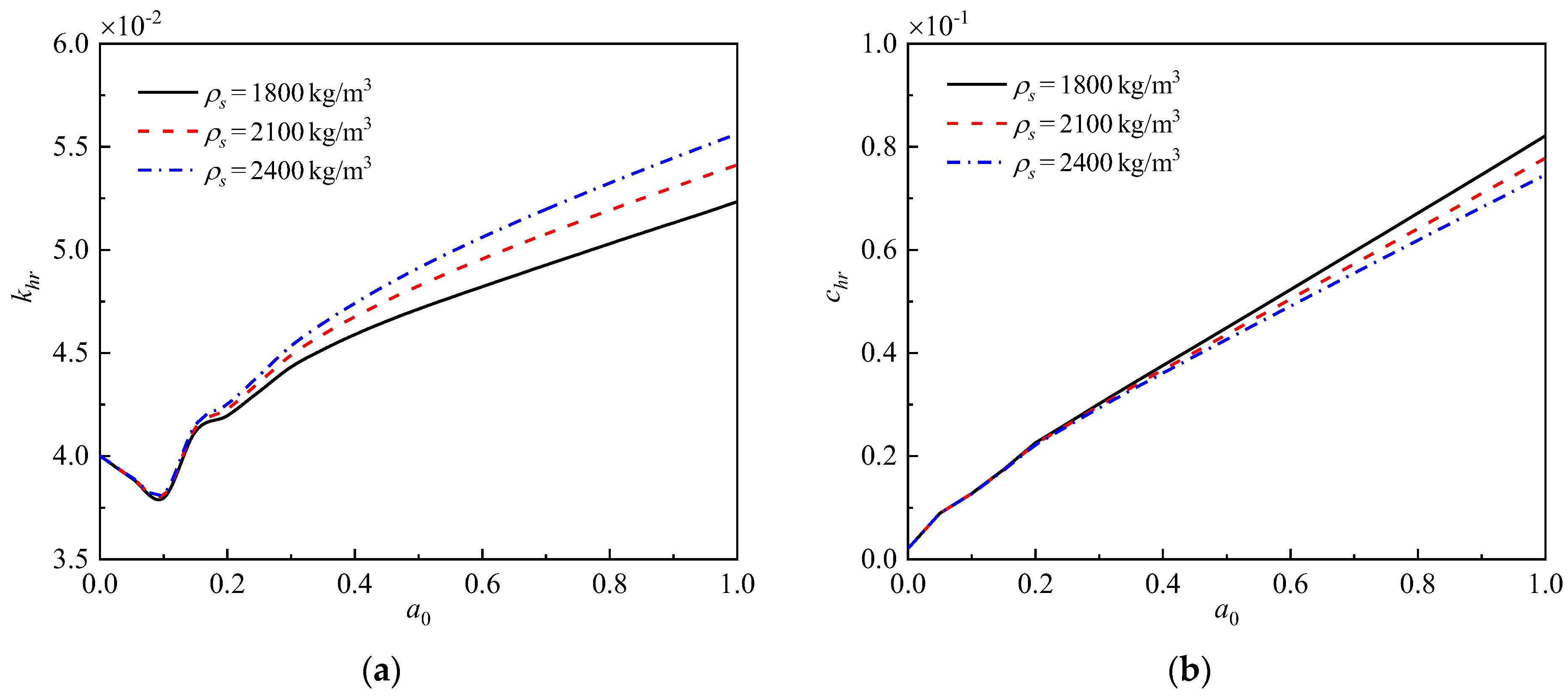
4.2. Parametric Analysis

This section presents a series of calculation examples and parametric analyses to discuss the influences of the radii and elastic moduli of the concrete-cored DCM pile, as well as the density of the surrounding soil on the horizontal dynamic impedance khh, rocking dynamic impedance krr, and horizontal–rocking dynamic impedance khr at the pile top of the concrete-cored DCM pile. Unless otherwise specified, the parameter values used for the calculation examples [6,33] are given in Table 1.
Figure 5, Figure 6 and Figure 7 show the influence of the radii of the concrete-cored DCM pile (including the radius rm of the cement–soil outer pile and the radius rc of the concrete inner pile) on the horizontal dynamic impedance, rocking dynamic impedance, and horizontal–rocking dynamic impedance of the pile top. Overall, the stiffness factor of the horizontal dynamic impedance decreases significantly with increasing frequency, whereas the stiffness factors of the rocking and horizontal–rocking dynamic impedances increase with increasing frequency. At the same time, the damping factors of the three types of dynamic impedances increase with increasing frequency. In addition, it can be seen from Figure 5, Figure 6 and Figure 7 that the radii of the concrete-cored DCM pile have a significant impact on the three types of dynamic impedances. Specifically, when the radius rm of the cement–soil outer pile remains unchanged, a decrease in the radius rc of the concrete inner pile reduces the stiffness and damping factors of the three types of dynamic impedances at the pile top. When the radius rc of the concrete inner pile remains unchanged, the increase in the radius rm of the cement–soil outer pile improves the value of the stiffness factor for the horizontal dynamic impedance in the low-frequency range (a0 < 0.4) but reduces that in the high-frequency range (a0 > 0.4). Meanwhile, the stiffness factors of the rocking and horizontal–rocking dynamic impedances, as well as the damping factors of the three types of dynamic impedances, increase as the radius rm of the cement–soil outer pile increases. Moreover, the radius rm of the cement–soil outer pile has a more significant influence on the damping factors than on the stiffness factors. Overall, for every 0.1 m increase in the radius rc of the concrete inner pile, the stiffness and damping factors of the three types of dynamic impedances increase by 1~3 times. On the other hand, for every 0.1 m increase in the radius rm of the cement–soil outer pile, the stiffness and damping factors of the three types of dynamic impedances increase by 1~1.5 times. In addition, the stiffness factor of the horizontal dynamic impedance reduces by 1~1.5 times in the high-frequency range (a0 > 0.4) for every 0.1 m increase in the radius rm of the cement–soil outer pile.
Figure 8, Figure 9 and Figure 10 depict the variations in the horizontal, rocking, and horizontal–rocking dynamic impedances with frequency under different elastic moduli of concrete-cored DCM piles. Overall, the elastic modulus of the concrete-cored DCM pile has a similar effect on the three types of dynamic impedances, whereas it has a more significant influence on the rocking and horizontal–rocking dynamic impedances. More specifically, increasing the elastic modulus of both the concrete inner pile and cement–soil outer pile improves the stiffness and damping factors of the three types of dynamic impedances. Apparently, the elastic modulus of the concrete inner pile has a more significant effect on the dynamic impedances of the concrete-cored DCM pile than the elastic modulus of the cement–soil outer pile. Overall, for every 5 GPa increase in the elastic modulus Ec of the concrete inner pile, the stiffness and damping factors of the three types of dynamic impedances increase by 1~1.5 times. Meanwhile, for every 2 MPa increase in the elastic modulus Em of the cement–soil outer pile, the stiffness and damping factors of the three types of dynamic impedances increase by 1~1.2 times. Hence, improving the elastic modulus of the cement–soil outer pile is crucial for enhancing the vibration resistance of concrete-cored DCM piles.
The influence of the soil density on the three types of dynamic impedances for the concrete-cored DCM pile is demonstrated in Figure 11, Figure 12 and Figure 13. It can be observed from Figure 11, Figure 12 and Figure 13 that the influence of soil density on the three types of dynamic impedances for the concrete-cored DCM pile is significant, and the influence of soil density on the stiffness and damping factors of the three types of dynamic impedances has a reverse trend. In detail, the increase in soil density enhances the stiffness factors of the three types of dynamic impedances, specifically for the horizontal and horizontal–rocking dynamic impedances. At the same time, the increase in soil density reduces the damping factors of the three types of dynamic impedances, and the greater the frequency, the more obvious the reduction. Overall, the density of the soil around the concrete-cored DCM pile mainly has a significant impact on the stiffness factors of the horizontal and horizontal–rocking dynamic impedances. Specifically, the stiffness factors of the horizontal and horizontal–rocking dynamic impedances increase by 2~3 times for every 300 kg/m3 increase in the density of the soil around the concrete-cored DCM pile, especially in the frequency region a0 > 0.2.
Liu et al. [34] have revealed that the in situ water content has a significant impact on the strength of DCM piles. Therefore, the influence of in situ water content on the dynamic behaviors of concrete-cored DCM piles should be mentioned here. Whether the in situ water content is too high or too low, it significantly reduces the physical parameters, such as the compressive strength and elastic modulus of DCM piles. Furthermore, the overall elastic modulus of the concrete-cored DCM pile decreases. The vibration resistance of the concrete-cored DCM pile is weakened as a result. In order to effectively avoid the impact of high or low in situ water content on the performance of concrete-cored DCM piles, various construction methods, such as the wet method (for low in situ water content), dry method (for high in situ water content), and even dry–wet method, have been developed during the construction process of DCM piles. However, the specifications and processes of relevant construction methods still need to be further improved.

5. Conclusions

In the present work, the lateral dynamic responses of a concrete-cored DCM pile in single-phase viscoelastic soil are discussed using theoretical deduction and parametric analysis. The proposed approach obtains a closed series form solution for the concrete-cored DCM pile with finite length. Then, the influence of the radius and elastic modulus of the concrete-cored DCM pile and the soil density of the lateral dynamic behavior of the concrete-cored pile–soil system are investigated. The main findings obtained in this work are summarized as follows: (i) the radii of the concrete inner pile and cement–soil outer pile have a significant influence on the dynamic impedances at the pile top of the concrete-cored DCM pile; (ii) increasing the elastic moduli of the concrete inner pile and cement–soil outer pile will be beneficial for improving the dynamic impedances at the pile top of the concrete-cored DCM pile; (iii) enhancement of the soil density will augment the stiffness factors of the three types of dynamic impedances but will reduce their damping factors.

Author Contributions

Conceptualization, G.S. and G.D.; methodology, H.L. and G.D.; software, H.L.; validation, G.S. and H.L.; investigation, X.C.; data curation, G.D.; writing—original draft preparation, G.S. and H.L.; writing—review and editing, X.C.; visualization, Y.D.; project administration, G.S. and Y.D.; funding acquisition, G.D. All authors have read and agreed to the published version of the manuscript.

Funding

This research was funded by the National Natural Science Foundation of China, grant numbers 52078128 and 52178317.

Data Availability Statement

The datasets generated during and/or analyzed during the current study are available from the corresponding authors upon reasonable request.

Conflicts of Interest

The authors declare no conflict of interest.

Appendix A

The expressions of s1s12 in Equation (55) are written as
s 1 = η 2 n 3 η 2 n 1 η 1 n 3 ,   s 2 = n 3 A G K η 2 n 1 η 1 n 3 ,   s 3 = y 4 y 4 y 1 y 3 y 2 s 4 = t 1 y 4 y 1 y 3 y 2 ,   s 5 = y 2 E I y 4 y 1 y 3 y 2 ,   s 6 = t 2 y 4 y 1 y 3 y 2
s 7 = η 1 n 1 η 1 n 3 η 2 n 1 ,   s 8 = n 1 A G K η 1 n 3 η 2 n 1 ,   s 9 = y 3 y 2 y 3 y 1 y 4 s 10 = t 3 y 2 y 3 y 1 y 4 ,   s 11 = y 1 E I y 2 y 3 y 1 y 4 ,   s 12 = t 4 y 2 y 3 y 1 y 4
with
y 1 = 1 + n = 1 K 2 Φ 1 n ,   y 2 = 1 + n = 1 K 4 Φ 1 n , y 3 = n 2 η 1 + n = 1 K 2 Φ 2 n g n ,   y 4 = n 4 η 2 + n = 1 K 4 Φ 2 n g n
t 1 = y 2 n = 1 s 1 K 1 + s 7 K 3 Φ 2 n g n y 4 n = 1 s 1 K 1 + s 7 K 3 Φ 1 n t 2 = y 2 n = 1 s 2 K 1 + s 8 K 3 Φ 2 n g n y 4 n = 1 s 2 K 1 + s 8 K 3 Φ 1 n
t 3 = y 1 n = 1 s 1 K 1 + s 7 K 3 Φ 2 n g n y 3 n = 1 s 1 K 1 + s 7 K 3 Φ 1 n t 4 = y 1 n = 1 s 2 K 1 + s 8 K 3 Φ 2 n g n y 3 n = 1 s 2 K 1 + s 8 K 3 Φ 1 n

Appendix B

The expressions of u1u8 in Equation (56) are written as
u 1 = s 3 cos η 1 H + s 9 cosh η 2 H
u 2 = s 1 sin η 1 H + s 4 cos η 1 H + s 7 sinh η 2 H + s 10 cosh η 2 H
u 3 = s 5 cos η 1 H + s 11 cosh η 2 H
u 4 = s 2 sin η 1 H + s 6 cos η 1 H + s 8 sinh η 2 H + s 12 cosh η 2 H
u 5 = s 3 n 2 sin η 1 H + n = 1 K 2 Φ 2 n sinh g n H + s 9 n 4 sinh η 2 H + n = 1 K 4 Φ 2 n sinh g n H
u 6 = s 1 n 1 cos η 1 H + n = 1 K 1 Φ 2 n sinh g n H + s 4 n 2 sin η 1 H + n = 1 K 2 Φ 2 n sinh g n H + s 7 n 3 cosh η 2 H + n = 1 K 3 Φ 2 n sinh g n H + s 10 n 4 sinh η 2 H + n = 1 K 4 Φ 2 n sinh g n H
u 7 = s 5 n 2 sin η 1 H + n = 1 K 2 Φ 2 n sinh g n H + s 11 n 4 sinh η 2 H + n = 1 K 4 Φ 2 n sinh g n H
u 8 = s 2 n 1 cos η 1 H + n = 1 K 1 Φ 2 n sinh g n H + s 6 n 2 sin η 1 H + n = 1 K 2 Φ 2 n sinh g n H + s 8 n 3 cosh η 2 H + n = 1 K 3 Φ 2 n sinh g n H + s 12 n 4 sinh η 2 H + n = 1 K 4 Φ 2 n sinh g n H

References

  1. Bergado, D.T.; Jamsawang, P.; Voottipruex, P.; Cheang, W. Behavior of deep cement mixing (DCM) and stiffened deep cement mixing (SDCM) piles under full scale tests and embankment loading. In Proceedings of the 1st International Symposium on Ground Improvement Technologies and Case Histories, Singapore, 9–12 December 2009; pp. 3–11. [Google Scholar]
  2. Voottipruex, P.; Suksawat, T.; Bergado, D.T.; Jamsawang, P. Numerical simulations and parametric study of SDCM and DCM piles under full scale axial and lateral loads. Comput. Geotech. 2011, 38, 318–329. [Google Scholar] [CrossRef]
  3. Voottipruex, P.; Bergado, D.T.; Suksawat, T.; Jamsawang, P.; Cheang, W. Behavior and Simulation of Deep Cement Mixing (DCM) and Stiffened Deep Cement Mixing (SDCM) Piles under Full Scale Loading. Soils Found. 2011, 51, 307–320. [Google Scholar] [CrossRef]
  4. Wang, A.; Zhang, D.; Deng, Y. Lateral response of single piles in cement-improved soil: Numerical and theoretical investigation. Comput. Geotech. 2018, 102, 164–178. [Google Scholar] [CrossRef]
  5. Wang, A.; Zhang, D.; Deng, Y. A Simplified Approach for Axial Response of Single Precast Concrete Piles in Cement-Treated Soil. Int. J. Civ. Eng. 2018, 16, 1491–1501. [Google Scholar] [CrossRef]
  6. Yu, J.; Xu, S.; Yang, X.; Chen, Z.; Gong, X. Settlement calculation of composite foundation with concrete-cored DCM pile under rigid foundation. J. Cent. South Univ. Sci. Technol. 2020, 51, 2111–2120. [Google Scholar]
  7. Zhang, C.; Liu, S.; Zhang, D.; Lai, F.; Lu, T.; Liu, Y. A modified equal-strain solution for consolidation behavior of composite foundation reinforced by precast concrete piles improved with cement-treated soil. Comput. Geotech. 2022, 150, 104905. [Google Scholar] [CrossRef]
  8. Han, Y.S.; Cheng, J.Y.; Zhou, M.; Ni, P.P.; Wang, Y.L. Experimental Study of Compaction and Expansion Effects Caused by Penetration of Core Pile During Construction of SDCM Pile. Int. J. Geomech. 2022, 22, 04022041. [Google Scholar] [CrossRef]
  9. Wang, A.; Zhang, D.; Zhang, Y. Seismic responses of pipe piles improved with cement-treated soil in sand. Chin. J. Geot. Eng. 2021, 43, 121–124. [Google Scholar]
  10. Zhang, D.; Wang, A.; Ding, X. Seismic response of pile groups improved with deep cement mixing columns in liquefiable sand: Shaking table tests. Can. Geotech. J. 2022, 59, 994–1006. [Google Scholar] [CrossRef]
  11. Makris, N.; Gazetas, G. Displacement Phase Differences in a Harmonically Oscillating Pile. Geotechnique 1993, 43, 135–150. [Google Scholar] [CrossRef]
  12. Makris, N. Soil-Pile Interaction during the Passage of Rayleigh-Waves—An Analytical Solution. Earthq. Eng. Struct. Dyn. 1994, 23, 153–167. [Google Scholar] [CrossRef]
  13. Makris, N.; Badoni, D. Seismic Response of Pile Groups under Oblique-Shear and Rayleigh-Waves. Earthq. Eng. Struct. Dyn. 1995, 24, 517–532. [Google Scholar] [CrossRef]
  14. Takewaki, I.; Kishida, A. Efficient analysis of pile-group effect on seismic stiffness and strength design of buildings. Soil Dyn. Earthq. Eng. 2005, 25, 355–367. [Google Scholar] [CrossRef]
  15. Anoyatis, G.; Mylonakis, G. Dynamic Winkler modulus for axially loaded piles. Geotechnique 2012, 62, 521–536. [Google Scholar] [CrossRef]
  16. Anoyatis, G.; Di Laora, R.; Mandolini, A.; Mylonakis, G. Kinematic response of single piles for different boundary conditions: Analytical solutions and normalization schemes. Soil Dyn. Earthq. Eng. 2013, 44, 183–195. [Google Scholar] [CrossRef]
  17. Anoyatis, G.; Di Laora, R.; Lemnitzer, A. Dynamic pile impedances for fixed-tip piles. Soil Dyn. Earthq. Eng. 2017, 97, 454–467. [Google Scholar] [CrossRef]
  18. Cui, C.Y.; Meng, K.; Xu, C.S.; Wang, B.L.; Xin, Y. Vertical vibration of a floating pile considering the incomplete bonding effect of the pile-soil interface. Comput. Geotech. 2022, 150, 104894. [Google Scholar] [CrossRef]
  19. Novak, M.; Aboul-Ella, F.; Nogami, T. Dynamic Soil Reactions for Plane Strain Case. J. Eng. Mech. Div. 1978, 104, 953–959. [Google Scholar] [CrossRef]
  20. Novak, M.; Aboul-Ella, F. Impedance Functions of Piles in Layered Media. J. Eng. Mech. Div. 1978, 104, 643–661. [Google Scholar] [CrossRef]
  21. Novak, M. Dynamic Stiffness and Damping of Piles. Can. Geotech. J. 1974, 11, 574–598. [Google Scholar] [CrossRef]
  22. Vaziri, H.; Han, Y.C. Impedance Functions of Piles in Inhomogeneous-Media. J. Geotech. Eng. ASCE 1993, 119, 1414–1430. [Google Scholar] [CrossRef]
  23. Vaziri, H.H. Impedance Functions to Model Boundary Zones with Nonreflection Interface Properties. Comput. Struct. 1994, 50, 263–272. [Google Scholar] [CrossRef]
  24. Zheng, C.J.; Cui, Y.Q.; Wu, C.; Luo, T.; Luan, L.B. Simplified analytical solution for horizontal seismic response of single piles to vertically incident S waves. Rock Soil Mech. 2023, 44, 327–336. [Google Scholar] [CrossRef]
  25. Anoyatis, G.; Lemnitzer, A. Dynamic pile impedances for laterally–loaded piles using improved Tajimi and Winkler formulations. Soil Dyn. Earthq. Eng. 2017, 92, 279–297. [Google Scholar] [CrossRef]
  26. Nogami, T.; Novak, M. Resistance of soil to a horizontally vibrating pile. Earthq. Eng. Struct. Dyn. 1977, 5, 249–261. [Google Scholar] [CrossRef]
  27. Novak, M.; Nogami, T. Soil-pile interaction in horizontal vibration. Earthq. Eng. Struct. Dyn. 1977, 5, 263–281. [Google Scholar] [CrossRef]
  28. Anoyatis, G.; Mylonakis, G.; Lemnitzer, A. Soil reaction to lateral harmonic pile motion. Soil Dyn. Earthq. Eng. 2016, 87, 164–179. [Google Scholar] [CrossRef]
  29. Zheng, C.; Luan, L.; Qin, H.; Zhou, H. Horizontal Dynamic Response of a Combined Loaded Large-Diameter Pipe Pile Simulated by the Timoshenko Beam Theory. Int. J. Struct. Stab. Dyn. 2020, 20, 2071003. [Google Scholar] [CrossRef]
  30. Zheng, C.; Kouretzis, G.; Luan, L.; Ding, X. Closed-form formulation for the response of single floating piles to lateral dynamic loads. Comput. Geotech. 2022, 152, 105042. [Google Scholar] [CrossRef]
  31. Yang, X.; Zhang, Y.; Liu, H.; Fan, X.; Jiang, G.; El Naggar, M.H.; Wu, W.; Liu, X. Analytical solution for lateral dynamic response of pile foundation embedded in unsaturated soil. Ocean Eng. 2022, 265, 112518. [Google Scholar] [CrossRef]
  32. Cui, C.; Liang, Z.; Xu, C.; Xin, Y.; Wang, B. Analytical solution for horizontal vibration of end-bearing single pile in radially heterogeneous saturated soil. Appl. Math. Model. 2023, 116, 65–83. [Google Scholar] [CrossRef]
  33. Ding, X.M.; Zheng, C.J.; Luan, L.B. Principles of Pile Dynamics; Science Press: Beijing, China, 2021. [Google Scholar]
  34. Liu, Y.; He, L.Q.; Jiang, Y.J.; Sun, M.M.; Chen, E.J.; Lee, F.-H. Effect of in situ water content variation on the spatial variation of strength of deep cement-mixed clay. Géotechnique 2019, 69, 391–405. [Google Scholar] [CrossRef]
Figure 1. Scheme for the concrete-cored DCM pile–soil system.
Buildings 13 01378 g001
Figure 2. Analysis element of concrete-cored DCM pile. (a) Cement–soil outer pile; (b) concrete inner pile.
Buildings 13 01378 g002
Figure 3. Solution flow chart of concrete-cored DCM pile under horizontal dynamic loads.
Buildings 13 01378 g003
Figure 4. Comparison curves. (a) Comparison with Novak and Nogami (1977) [27]. (b) Comparison with Ding et al. (2021) [33].
Buildings 13 01378 g004
Figure 5. Influence of the radii of concrete-cored DCM pile on horizontal dynamic impedance. (a) Stiffness factor. (b) Damping factor.
Buildings 13 01378 g005
Figure 6. Influence of the radii of concrete-cored DCM pile on rocking dynamic impedance. (a) Stiffness factor. (b) Damping factor.
Buildings 13 01378 g006
Figure 7. Influence of the radii of concrete-cored DCM pile on horizontal–rocking dynamic impedance. (a) Stiffness factor. (b) Damping factor.
Buildings 13 01378 g007
Figure 8. Influence of the elastic moduli of concrete-cored DCM pile on horizontal dynamic impedance. (a) Stiffness factor. (b) Damping factor.
Buildings 13 01378 g008
Figure 9. Influence of the elastic moduli of concrete-cored DCM pile on rocking dynamic impedance. (a) Stiffness factor. (b) Damping factor.
Buildings 13 01378 g009
Figure 10. Influence of the elastic moduli of concrete-cored DCM pile on horizontal–rocking dynamic impedance. (a) Stiffness factor. (b) Damping factor.
Buildings 13 01378 g010
Figure 11. Influence of the soil density on horizontal dynamic impedance. (a) Stiffness factor. (b) Damping factor.
Buildings 13 01378 g011
Figure 12. Influence of the soil density on rocking dynamic impedance. (a) Stiffness factor. (b) Damping factor.
Buildings 13 01378 g012
Figure 13. Influence of the soil density on horizontal–rocking dynamic impedance. (a) Stiffness factor. (b) Damping factor.
Buildings 13 01378 g013
Table 1. Physical parameters.
Media TypeParameter Value
Surrounding soilDensity ρs = 1800 kg/m3
Lamé constant λs = μs = 10 MPa
Damping ratio βs = 0.05
Concrete inner pileElastic modulus Ec = 20 GPa
Poisson’s ratio νc = 0.2
Density ρc = 2350 kg/m3
Radius rc = 0.2 m
Length H = 10 m
Cement–soil outer pileElastic modulus Em = 300 MPa
Poisson’s ratio νm = 0.25
Density ρm = 2010 kg/m3
Radius rm = 0.4 m
Length H = 10 m
Disclaimer/Publisher’s Note: The statements, opinions and data contained in all publications are solely those of the individual author(s) and contributor(s) and not of MDPI and/or the editor(s). MDPI and/or the editor(s) disclaim responsibility for any injury to people or property resulting from any ideas, methods, instructions or products referred to in the content.

