Abstract
Since the 1990s, mass timber constructions have become more and more popular. This type of construction has characteristics that are ideal for incorporating building information modeling (BIM). A mass timber structure implies offsite prefabrication at the factory, which generates modeling specificities. Although digitalization and BIM are becoming more and more common, and some studies have focused on BIM for mass timber construction, none of them focus on model checking for mass timber construction. In construction projects, there is still no general method that synthesizes the possibilities offered by BIM-based model checking in general, and research on the conformity of mass timber models in particular is almost non-existent. Our research objective is to provide a general step-by-step method summarizing the process of model compliance study with dedicated tools. To conduct this work, we first solidified our understanding of the problem by interviewing professionals from the mass timber construction industry. Next, we developed our method iteratively, supported by tools, and then validated it with three model-checking case studies. This method consists of five steps: checking the specifications, digital environment implementation, requirement deciphering, calculation, and compliance results’ analysis. We then applied our method in three case studies. The results of the case studies are mixed: some audits were successful, while others were not, because barriers to auditing were encountered (missing information, impossible interpretation of data for the model properties, etc.). The obstacles encountered show that, to be efficient, BIM must be conducted on high-quality models, which is not often the case in real-life situations.
1. Introduction
With the current development of digital tools for the architecture, engineering, and construction (AEC) industry, it is becoming more and more common to work with a 3D digital model to design, build, and operate a building. Building information modeling (BIM) is the main digital approach to construction projects; it allows the centralization of data, the planning of the work, and the coordination of a project around a single digital model. The compliance study of digital models is therefore an important step in designing and validating a digital working model. There are already processes in place to ensure compliance with the building code, but there are other requirements that need to be addressed as well. Mass timber constructions are required, for example, to be compliant with the manufacturing capabilities of the CLT plant. Numerous constraints linked to the prefabrication stage offsite must be taken into account. While performing such verification by hand is time-consuming, BIM tools would allow the process to be automated and extended to a large number of models. A digital model can be checked in many ways, and several tools and software dedicated to model verification are available. Certainly, numerous studies have dealt with geometry clashes utilizing the scan-to-BIM method. However, other types of checking exist and it is not clear which BIM checking tool is most appropriate for each different type of checking. For designers and actors in the AEC industry working in the design phase, it would indeed be helpful to know which type of verification is possible with which tool and which verification type is automatable or not.
Certain categories of projects require the use of BIM more than others and therefore require correct conduct model conformity studies. This is the case for mass timber constructions, whose new technology (offsite construction, new non-standardized materials, etc.) implies particular verifications. The objective of this study is to present a five-step method for the conformity assessment of digital models and to then perform a verification application of a digital model of a mass timber building.
After presenting some related works in the next section, an overview of the suggested method is introduced. Each of the five steps are detailed: verifying the specifications, digital environment implementation, requirement deciphering, calculation, and analysis of compliance based on the results. The five-step method is applied to three case studies in a mass timber building context as proof of concept in the fourth section. For these applications, we detail precisely the context in which we perform the checking based on our interviews of some professionals in the field. A discussion and a conclusion about the research results conclude the paper, including the limits of this method and suggestions for future work.
2. Related Works
2.1. Mass Timber Construction
The timber industry is considerable in Canada. In 2020, the wood product industry contributed 6% to revenue from goods manufactured in the country of a value of CAD 635.1 billion [1]. In Quebec in particular, forests cover more than half of the territory or more than 900,000 km² [2]. However, it is only in 2012 that the technology of mass timber construction appeared in Canada, while it took place in the 1990s in Europe. In 2019, the production of cross-laminated (CLT) panels was 1.44 million m3 worldwide; according to the United Nations, this volume will double by 2025 [3]. Mass timber construction is a promising technology both structurally and sustainably. The objective of this subsection is to present this material and the resulting model-checking requirements.
Two types of wood structures are identified in the literature: light frame and mass timber. Mass timber structures are characterized by the use of large panels and columns of preassembled wood. They are laminated from smaller boards or lamella into larger structural components. Mass timber constructions benefit from the enhanced performance of this manufacturing technology (rigidity, lightness), in addition to the performance due to the use of wood as a material (durability, insulation, sustainability, and aesthetics).
The recent development of mass timber construction has made it possible to increase the number of floors in wood-framed buildings because the bi-directionality of CLT panels provides stability and rigidity similar to that of reinforced concrete. While light frame structures are entirely built onsite, mass timber constructions are prefabricated offsite and then assembled. In this section, offsite construction particularities are described, followed by mass timber particularities, to better understand the main challenges involved in this type of project.
Offsite construction is a type of construction in which pieces of a building are manufactured at the plant and then assembled onsite. Digitalization and digital tools offer a new approach to modular and offsite projects [4]. They must be designed while considering the manufacturing conditions at a plant. This aspect directly influences has the design process. We categorize these factors into three parts: prefabrication at the plant, non-adapted regulations, and the transport of prefabricated elements.
- Prefabrication at the plant. Mass production at a plant is cost-effective [5]. The controlled environment (temperature, humidity, electricity, etc.) allows the manufacturing process to be automated, ensuring a faster and more risk-free manufacturing process [4]. This automation involves the industrialization of the manufacturing process and thus the standardization of elements in high quantities. Prefabrication is relevant only for the following materials: steel, aluminum, and wood. In this context, concrete is not a suitable material.
- Non-adapted regulations. The current codes and regulations do not distinguish offsite construction from classic construction in situ [6].
- Transport of prefabricated elements. Building parts manufactured at a plant must be transported to the construction site. In addition to the transport, the assembly and storage must be considered. Those stages limit the total volume and weight that can be accommodated. Modular parts have to be designed such that as little empty space as possible will be transported. To optimize the elements’ storage duration, an optimal onsite delivery frequency must be determined. Thus, the whole transport process of modular elements has to be considered during the design phase. This aspect is referred to as the notion of design for manufacturing and assembly (DfMA); prefabricated modules are designed to make the manufacturing, the assembly, and the delivery as easy as possible.
Mass timber construction requires the prefabrication of mass timber elements such as CLT panels and glulam posts and beams at the plant. Furthermore, mass timber as a specific material technology has its unique particularities. These aspects influence the design of the building, therefore constraints during the conformity study of the model are implied. We classify them into three categories: offsite prefabrication, wood as mass timber, and the related regulations.
- Offsite prefabrication. Due to the manufacturing process of mass timber, such constructions imply offsite construction particularities. Additionally, the design must consider the manufacturing capabilities of the CLT plant: the facilities, the production infrastructure, the storage capacity, the production volume, etc. The equipment and the infrastructure at the plant limit a prefabricated part’s dimensions. While a building is usually a customer-oriented prototype, elements prefabricated at the factory are product-oriented.
- Wood as mass timber. Certain requirements linked to the use of mass timber as a material must be considered. The manufacturing process of CLT panels by layers implies specific structural resistance. The ideal ratio between the span and the panel thickness is recommended by the manufacturer.
- Related regulations. Timber building is bound by regulations and codes, with specific codes for mass timber building. These regulations are presented in the next paragraph. While some European and North American countries have adjusted their building codes to allow the construction of mid-rise and in some cases high-rise buildings out of wood, many others still need to adopt appropriate regulations [7].
Like all buildings, mass timber ones must be built in compliance with current regulations. Our literature review has revealed that in addition to common building codes, some specific regulations concern wood and mass timber construction. The norm CSA086 from the National Building Code of Canada specifies the calculation rules for wooden structures [8]. Standard ANSI/APA PRG 320 is dedicated to CLT construction [9] and the norm CSA O122 to glulam [10]. Pelletier et al. focus on mass timber encapsulated buildings of up to 12 stories [11]. The domain expert Karacabeyli has proposed a CLT handbook with FP Innovations [12] and a guide for tall wood buildings in Canada [13]. However, the current codes do not distinguish between combustible construction systems, i.e., light frame construction, column and beam systems, structurally engineered wood, glulam, cross-laminated wood, and hybrid construction [11].
These codes suggest various mass timber requirements that impact the design. The norm ANSI/APA PRG 320 [9] defines geometric requirements for CLT panels. The maximal thickness is 20 inches (508 mm), and the dimensional tolerances for the length, width, and thickness of a CLT panel are also specified. The ideal thickness of the lamellas is stated as between 5/8 of an inch (16 mm) and 2 inches (51 mm). Karacabeyli’s guide [13] proposes an objective-based code (as opposed to a performance-based code). He advocates maximum use of prefabrication to reduce costs and increase construction efficiency. To optimize the vertical loads, he recommends having as many large spans as possible in the upper floors, i.e., few beams. The available thickness of the panel determines the possible span and its performance against fire.
These specificities impact a building’s design and thus its digital model. Several issues must be considered in the modeling. As noted earlier, transport, logistics, delivery, storage, and assembly are some of the specific stakes to consider. The transport stage limits the size (and weight) of prefabricated modules. It is also necessary to take into account road transport regulations and if there will be a need for exceptional convoys, authorizations, etc. A maximum width of 3.5 m is standard for road transport [5]. For classic 3D modular construction, it is important to not transport or store too much vacuum, but with prefabricated mass timber 2D panels, this is not a major consideration. The repeatability of design is also important to consider, because construction offsite at the factory is only relevant for standardized buildings (residential buildings, dormitories, hotels, hospitals, etc.) [4]. The more repetitive a building design is, the more attractive the mass timber option becomes.
Thus, a building must be thought of from the perspective of prefabrication from the design state. Unlike conventional constructions, it is necessary to work in collaboration with each trade from the beginning, as modeling decisions must be made much earlier and no rework is possible. Offsite projects imply a high level of integration: collaboration between designers and manufacturers, the definition of roles and responsibilities, and the use of a collaborative platform for the model [6]. To achieve this level of collaboration, a collaborative platform such as a BIM tool is required. Moreover, the design–bid–build approach is not suitable for prefabrication; instead, the integration project delivery (IPD) approach fits better in mass timber construction. BIM and offsite construction are closely related [14].
The digital approach benefits each stage of mass timber construction. Computer-aided design (CAD) modeling software and parametric design in visual programming tools are used at the modeling stage. For the prefabrication at the plant, 2D industrial drawings of prefabricated parts can be extracted from the 3D digital model directly to computer numerical control (CNC) machines. Digital planning management is key to the delivery of just-in-time modules to limit travel and optimize storage. In particular, BIM offers the possibility to federate digital models (architectural, structural, and mechanical, electrical, and plumbing (MEP), to proceed with time simulation (BIM 4D) and to perform comparative analyses (e.g., costs, GHG emissions). The BIM offers the advantage of centralization around the same model, thereby allowing model checking, including the ability to study its compliance with current building codes and regulations and with offsite plant manufacturing capabilities. A few companies utilize BIM in the wooden construction manufacturing process, i.e., Sieveke GmbH and Wolf System/Haus, both from Germany.
The second section of the literature review presents the state of the art of digital model checking based on the use of BIM.
2.2. BIM-Based Model Checking
In the last few decades, the construction industry has seen the deployment of the digital BIM approach. This approach involves using a multidimensional digital model to document and simulate the design, construction, and operation of a built asset. Several ISO standards regulate BIM implementation, in particular ISO 19650. This international standard concerns BIM processes and exposes the principles to be applied for the modeling of the data of a construction project and the management of the information during the life cycle of buildings. Among the various uses of BIM—computer-aided design of buildings, 3D visualization of models, BIM management and coordination, BIM 4D planning, quantity takeoff, BIM 5D cost estimation, etc.—model checking is one of its most relevant uses. While many studies have focused on BIM coordination and the degree of BIM adoption within companies (best practices, barriers to adoption, etc.), few articles have covered digital model verification.
Since their introduction, the verification of digital mock-ups has almost always been carried out manually, a long and tedious process. Several aspects of building standards are subject to verification (acoustics, soundproofing, thermal quality, insulation, fire safety, structural resistance to vibrations, shocks, and earthquakes, among others). Since the development of BIM tools, it has been possible to perform this verification digitally, with a process called BIM-based model checking (BMC) [15]. Saving time is especially important when a model is composed of a large number of elements and a large volume of data. Hjelseth devoted an entire chapter to this situation [16]. Others use the term automatic code compliance checking when a code validation tool is used to check the parameters of a model according to a specific code (building code, etc.).
Applied to the model-checking stage, BIM can increase the quality of the design by displaying the degree of integration between components, detecting potential collisions, and checking the prefabrication lines of connections [17], for example. Hjelseth presents the current developments and the potential in BMC. Its use can be one of the BIM maturity indicators, and Hjelseth declares that interoperability must be improved for the use of BMC to be implemented more broadly. Digital clash detection greatly improves the traditional quality assessment of drawings; BMC becomes a worthwhile option when a huge amount of elements must be managed. However, digital clash detection is still too approximate and lacks accuracy. The poor quality of current models hinders the development of a good digital checking process. This situation highlights a major issue: if a model is not consistent enough and if it has poor information quality, digital model checking cannot be carried out.
In a theoretical study, Hjelseth suggests the following four types of checking according to the nature of their outcomes [18]:
- Validation Checking compares the model with predefined criteria. The outcome can be: “Pass”, “Fail”, or “Not checked”.
- Model Content Checking examines the BIM model automatically for a specific purpose (e.g., for the use of Construction Operations Building information exchange (COBie)). The outcome has two options: identified or not identified.
- Smart object checking evaluates a model’s integration and adaptation. A proposal of an adapted object is made according to its environment. The object itself observes its environment and automatically adapts to it by following embedded behavior rules or algorithms. The outcome is an adapted object or a modified model.
- Design Option Checking consists of guidance. Proposals, advice, and options are suggested to guide a designer as part of a knowledge system for selecting relevant solutions. For the moment, dedicated software solutions are not known. The Design Option Checking concept is intended to guide the designer to consider a large range of realistic solutions. This type of checking is closely related to best practices and decision support systems, but to date this concept has not been implemented in the construction industry.
Version 3.0 of the BIM Project Execution Planning Guide suggests four steps to review a design model [19].
- A Visual Check ensures that there are no unintended model components and that the design intent has been followed by using navigation software.
- An Interference Check detects problems in the model where two building components are clashing, identified by conflict detection software.
- A Standards Check ensures that the model is up to the standards agreed upon by the team.
- Element Validation ensures that the dataset has no undefined or incorrectly defined elements.
This classification process is intended for model quality checking [19]. It evaluates the design quality: is the mockup quality sufficient to properly operate the model? However, these criteria do not evaluate the model constructability or its built regulation compliance.
Others have proposed levels of BMC; the five levels of BMC maturity proposed by Hjelseth [15] according to Succar studies published in 2009 [20] are:
- Clash detection checking;
- Adjusted model checking;
- Specific purpose checking;
- Integrated model checking; and
- Pervasive model checking.
The various levels indicate that BMC offers multiple checking options from clash detection to advanced code compliance verification. Such multilevel categorization implies that level n + 1 necessarily includes level n, but this must be verified. Heljseth describes these levels in a two-axis matrix [15]. This classification based on those two axes, digital rule complexity and the quality of the model’s digital data/information, suggests that BMC levels are directly dependent upon these two aspects. If the former depends upon what you want to verify, the latter depends upon the model for which you want to do the checking. It is obvious that for each project those parameters may change. This classification helps us to assess the checking possibilities of each tool.
The importance of model information quality has been highlighted repeatedly. The taxonomy for the classification of BMC level is based on two criteria (taxa) [16]: the requirement of the content of information in the BIM file (“the I in BIM”) and the complexity in the ruleset (intelligence of rules).
Code compliance checking is a part of model checking. This type of verification evaluates how completely a model is compliant with code clauses. Several articles propose code clause classifications to be verified according to their nature, including how to decipher a statement of rules in order to automate them. One challenge is how to convert design rules and regulations into digital rules (computable rules). While some clauses’ provisions can be transformed, some others cannot.
Classifications of code clauses have been developed as part of evaluating their potential automation. Malsane et al. has worked in the context of the UK, where regulations are evolving rapidly [21]. The automation of their proposed verification approach is centered around the common interoperability of the Industry Foundation Classes (IFC) formats. While software and digital tools are generic and international, regulations and codes are specific and local. They differentiate two types of clauses, declarative (computer-interpretable) and informative (non-interpretable, requiring human interpretation) [21]. In 2018, Nawari suggested another type of clause classification. He distinguished four types of clauses [22] that effectively classify the provisions of any given building code into four main categories [22]. These categorizations help to identify for which clauses the checking can be automatized.
- Conditional clauses: These can be interpreted directly from the textual document into a set of formal rules. Typical features include rules with specific values.
- Contents clauses: This type of clause cannot be transformed into TRUE or FALSE expressions. These clauses are normally utilized for descriptions and definitions.
- Ambiguous clauses: These clauses have subjective provisions. They normally include words such as approximately, about, relatively, close to, far from, maybe, etc.
- Dependent clauses: Some clauses are dependent on others, which means some provisions are only suitable for a particular condition.
To perform an automated assessment of building design using BIM in the initial design phase, it is necessary to go through a process of elaborating and “manufacturing” appropriate rules so that they are computer readable [23]. Transcribing design rules into machine-interpretable code is still carried out by humans, but some processes use an IFC-compatible execution algorithm in hard code to automate. Others rely on a logical interpretation based on the syntactic, lexical, and semantic aspects of the rules.
Currently, design review is carried out using both automatic and semi-automatic processes based on hard-coded rules [24]. While these are suitable for specific applications, there are some disadvantages: rules based on hard code are difficult to modify and there is no generalized framework for adaptable regulation models, so they are not transposable to other engineering domains. A generalized adaptive framework in the standard IFC format that allows automation of the code compliance verification process has been proposed to achieve efficiency, quality, and profitability of the design [24]. That work focuses on the development of a theoretical context of the framework to transform the code into a computer-readable model.
Using data from the Korea Building Act, Kim et al. worked on the transformation of clauses into machine-interpretable code [23]. KBim Visual Language (KBVL) is a visual language that makes it possible to generate code automatically after identifying and processing each constituent element of a clause statement (relative property, verb, relation, etc.) from a code. The automatically generated code is then exported in a ruleset file to rule-checking software. This method separates the rule-making and rule-checking processes. The ability to create and modify rules with visual language will allow the rules to evolve with the regulations, specifically for wood buildings where regulations are changing and will become more precise in the future.
Preidel’s work analyzes two automation approaches [25]: one based on Visual Code Checking Language and a semi-automated approach applied to the German fire safety code. Since 1995, Singapore has been performing checks with the CORENET tool, which uses the hard-coded FORNAX library.
In 2009, Eastman et al. defined four stages that structure rule checking [26]: (1) rule interpretation, (2) building model preparation, (3) the rule execution phase, and (4) the reporting of the check results. A few years later, Nawari [22] and Preidel [25] reused this framework. They all insist on the importance of the elaboration stage, of “manufacturing” appropriate rules so that they are readable by the computer. Some challenges regarding BMC remain. When the process lacks transparency and visibility to the user, it is difficult to understand it. For legal reasons, someone must be responsible for compliance verification; this responsibility cannot be transferred to a machine [25].
Recently, Kincelova et al. investigated the use of BIM to improve fire protection integration in high-rise timber buildings [27], focusing on the integration of passive fire safety into the design process using BIM tools. A coherent method that addresses the issues of fire safety has been proposed. Moreover, to assess the possibilities of automated compliance checking, Kincelova et al. evaluated eight different checking tools in terms of code compliance checking applied to fire protection [28]. Their results suggest that the existing code-checking solutions fail to address the fire protection challenges because they have specific needs in terms of modeling.
2.3. Literature Review Conclusion
Today, there is a growing need to use BIM for construction projects, in particular for mass timber projects. While some digital tools are already being used for the whole process, very few construction projects have used BIM-based model checking to verify digital models.
A review of the literature has shown that, in theory, BMC has great potential to accelerate the verification stage of a model. Indeed, when all the application’s conditions are met, BIM offers impressive potential for productivity gains through digitalization. To date, this digital verification practice has been studied theoretically from certain points of view, but there is no general and systematic method dedicated to its implementation. Unsurprisingly, there is a gap between theoretical research and the practical use of such verification tools. There is also a lack of studies on verification needs according to different types of construction projects. For example, an infrastructure project will have different verification needs than a prefabricated modular construction. BMC allows the challenges of mass timber construction to be considered. Several conditions must be met before BMC can be implemented; we focus on how best to implement BMC and while considering the mass timber specificities.
3. Materials and Methods
3.1. Statement of Purpose
This research work intends to facilitate the step of verification and compliance study of a digital model of a mass timber building. For this purpose, we first study the model-checking process in a general way and then establish an overview of the possibilities offered by BIM-based verification, which is still missing from the literature. Considering the particularities of mass timber, we perform three model checks of a mass timber model.
3.2. Objectives of the Research
The main objective of the research is to propose a compliance study process based on BIM of mass timber digital models. For this, the specific objectives are:
- Characterize the business needs of mass timber projects;
- Propose a general method, supported by tools, that synthesizes the steps of this process;
- Establish the proof of concept of the advanced method through case studies.
3.3. The Main Stages of the Research
To conduct this research work, we followed distinct stages. First, understanding of the issues, then developing a method, and then validation of that method.
3.3.1. Understanding of the Issues
The first step of the research process consists in understanding of the issues. The problem was evaluated through interviews with experts in the field.
Here, the issues are two-fold: the challenges concerning the adoption of mass timber construction in the AEC industry, and the adoption of model checking and the digitalization of the task. Our first study focused on offsite construction, DfMA, and related prefabrication issues, including the benefits and drawbacks of using BIM for prefabricated construction. While many company reports or guides on the subject of mass timber in the construction industry exist, few articles or scientific studies have studied it rigorously and scientifically, with only a small number of research papers having focused on BIM for mass timber projects. To understand how much mass timber construction is being used today, we investigated large mass timber structures that have been built recently. Most of these received a considerable amount of press, including these three: Brocks Common, a student residence in Vancouver; HoHo Vienna, an 84 m high building in Austria; and Mjøstårnet in Norway, which was the tallest CLT building in 2019 when it was built. We also consulted the Canadian standards, codes for construction, and norms about wood construction.
We had the opportunity to interview key players in the mass timber industry. We chose to interview the manufacturers and designers of a single recently built mass timber project. Focusing our case study on a single project allowed us to target some of the existing issues while conducting multi-perspective interviews. This is one of the limitations of our case study as it does not represent a general case of mass timber projects. It would be interesting to extend the future work to other projects for a larger-scale validation.
We conducted three interviews with the following objectives: understand the challenges of mass timber, understand the issues, and confirm the issues. We met with two engineers from a firm whose expertise is the manufacturing of CLT and an architect who worked on the design of a CLT residential complex built in Montreal. We conducted a one-hour virtual interview with the engineers and then met with them in person for two hours. They discussed the problems in the collaboration between the architect, the MEP subcontractors, and the designer-suppliers of mass timber for a building project built in Montreal. In addition, they described the particularities of manufacturing at the factory, the relevance of using BIM for mass timber, and the difficulties linked to the non-standardization of this new material. Shortly after, we met virtually with the architect of the same project for a one-hour interview focused on the design difficulties to consider with mass timber and BIM.
3.3.2. Iterative Development of the Solution
We developed a checking method step by step in an iterative way. To build the steps, we performed simple verifications with several models. Those verifications allowed us to easily characterize the successive steps of the method, as well as to propose tools to help the user at each step. The process followed was an iterative one. The proposed tools are based on scientific theoretical foundations and summarize information about each scientific notion evoked.
3.3.3. Validation of the Suggested Method with Material Description
In the third step, we conducted three model-checking processes using the proposed method to make the proof of concept of the method. The three models are: a standard BIM educative model, the architectural model of Arbora, a massive timber condominium complex constructed in Montreal in the early 2010s, and the associated MEP model. Revit, its plugin Dynamo, Navisworks, and Solibri as were used to conduct tests and perform the checking case studies.
The three checks conducted were selected from various sources and types. These are all requirements related to the design of a mass timber building. The first consists in checking that the span of a CLT slab does not exceed 18 times its thickness. The second is to check the correct positioning of the drillings for MEP conduits. In the third, we verified that the same CLT panel appears a minimum of 20 times in the model. We then identified the recurring obstacles and the main difficulties in the process after conducting several model checking cycles.
4. Formalization and Implementation of the Suggested Model-Checking Method
This fourth section is dedicated to the presentation of the five-step method to conduct BIM-based model checking (BMC). After a general overview, each step is detailed below.
4.1. General Overview
The process of numerical model verification is complex. We studied this process from A to Z and integrated it into a complete method for a non-expert user. To do this, we completely reviewed and deconstructed each of the actions and steps necessary to perform model checking. As the method is BIM-based, several factors come into play, in particular the digitalization of tasks.
This method is intended for both novice and intermediate designers who want to automate their processes. Even before performing model checking, with this method, a novice designer can better understand BMC’s main challenges and gain an overview of the resources and application conditions required for performing model checking. The intermediate user who already performs digital model checking can learn more about the digitization of this task and its potential automation.
This method has a few conditions before it can be implemented. In particular, there must already be an exploitable 3D model of the building asset. Assuming that the virtual model is designed in the same way as the real building, checking the conformity of the model allows us to ensure the conformity of the real building. Thus, the method may not lead to a conclusive result if the model is not consistent and complete enough in its information.
We identified five major steps of this checking process:
- Step 1: Specification of the checking needs;
- Step 2: Implementation of the BIM environment;
- Step 3: Analysis of the requirements;
- Step 4: Simulation and calculation of the results; and
- Step 5: Analysis of the results.
Step one specifies what needs to be checked. Step two allows the user to adequately build the digital environment so that the model is consistent and complete. Step three allows the user to decipher the content of the requirements to be verified in order to implement their verification. The simulation and the test calculations to study the conformity or the non-conformity of the model are performed in the fourth step. Finally, the last step is the analysis of the compliance results.
Figure 1 below presents an overview of the suggested checking method.

Figure 1.
Overview of the method.
4.2. Step 1: Specification of the Checking Needs
The first step in the process concerns the project’s requirements. The user has to identify the specific needs for checking for a project and what stage of the project they have reached, as different things need to be checked as the project progresses. Some projects, more than others, have particularities that will have an impact on verification: prefabricated buildings, building with high seismic constraints, mass timber buildings, building for certification, etc.
Characterizing the specifications of a project can be carried out by listing its particularities. This includes understanding a building’s intended use, a description of the location of the construction site, and the conditions of the building’s use. It is also necessary to evaluate the progress of the project because some verifications are carried out at specific times. To identify the requirements to which the model must conform, it is necessary to consult the regulations in force, as well as to study the client’s requirements and those of the builders. For example, for offsite construction, the builder may have certain constraints to verify.
4.3. Step 2: Implementation of the BIM Environment
The second step in the method ensures that the BIM environment is well implemented. Depending on the maturity of BIM adoption in the company, implementing an adapted BIM environment may be relatively easy. The idea is to obtain a workable digital mockup of the project utilizing appropriate tools. Model compliance checking requires some specific BIM installation to take advantage of this digital technology. In the BIM workflow, all design activities are model-driven [22]. The model is a central element of work, and so its quality is crucial. The model must contain the necessary information and properties to allow for automated compliance checking [22].
To perform appropriate verifications, the company’s digital BIM context, in particular the verification context, must be characterized (Suggested tool n°1). Next, the level of development (LOD) of the model must be identified to ensure that the verifications can be carried out and that the model is consistent enough, which means that it contains the minimum required information (Suggested tool n°2). Once the model is usable, the appropriate software must be selected and the manner in which to conduct it (Suggested tool n°3). In addition, it is necessary to ensure that the format of the models is compatible with the software. The three suggested tools are detailed below.
4.3.1. Suggested Tool n°1: Metamodel for Checking Context Characterization
As observed in the related works, BIM-based model checking is an important and complex stage during the design of a built asset. It requires considerable resources that must interact with each other. The metamodel proposed in Figure 2 consists of a diagram with classes of elements and their properties. This allows description of a situation in detail, i.e., the context of automated verification.
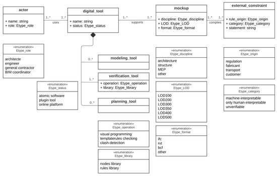
Figure 2.
Metamodel of the required BIM environment.
The model-driven engineering (MDE) approach suggests describing one reality. The numbers above lines describes allow you to count. The asterisks mean more than one. Three levels of modeling exist:
- M0: The reality;
- M1: The described reality; and
- M2: The related metamodel.
For our study, level M0 is the architect’s reality. For example: Architect Pierre uses Revit, an independent modeling software, which supports a structural mockup in .rvt format with a level of development (LOD) of 350. The mockup has to be compliant with an external constraint required by the manufacturer, which is computer-interpretable. Its statement is: CLT slab length has to be less than or equal to 40 feet (12 m). Level M1 is described in Table 1.

Table 1.
Level M1 of modeling.
4.3.2. Suggested Tool n°2: Identification Matrix of the LOD of a Model
The level of development (LOD) of an element indicates the level of detail of a digital element in the model. It includes knowing the exact LOD of a digital model, the BIM deliverables to be specified, and if the model is consistent enough to perform checking.
The LOD includes geometrical and non-geometrical information such as quantities, the shape, size, location, orientation, interface(s) with other building systems, and fabrication–assembly–installation information [29]. The LOD of elements may vary at different stages in the design and construction process. Each element in a model has its LOD. The LOD describes the information contained in the digital element, and so it determines the usability of the digital model. Starting from LOD300, the properties of an element can be measured directly from a model without referring to non-modeled information such as notes or dimension call-outs [29].
Based on the guide entitled The LOD Specification Part I from BIM Forum [29] and the basic LOD definitions developed by the AIA for the AIA G202-2013 Building Information Modeling Protocol Form, we suggest the items and values in Table 2, which summarize the differences between each LOD. The first levels differ by the quality of the model element information: approximate, exact, or non-existent.
Table 2.
Matrix for LOD identification.
Admittedly, the concept of LOD is quite old and some find it a limited view of model development. To achieve better results, the level of required information must be defined for each single part of the model, according to real information needs.
4.3.3. Suggested Tool n°3: Comparative Analyses of Four BIM-Based Checking Tools
As observed in the related works, BIM-based model checking offers a wide range of checking possibilities depending on the tools used. We studied the checking capabilities of four BIM-based checking software packages. Our aim is to compare the four main commercially available digital verification tools: Dynamo, Grasshopper, Navisworks, and Solibri Model Checker (SMC). Each of them has been reviewed according to selected functionalities based on various criteria. The comparative study helps the model reviewer better understand the different softwares’ capabilities.
Two comparisons were conducted: one comparing the user–tool interaction (see Table 3) and the other focusing on the verification capabilities of the tools (see Table 4). The comparison criteria are the functionalities expected by the verification software based on our software experience and on the literature. For the first comparative study, we regrouped the criteria into three categories: main features, interoperability, and usability. For the second comparison, the verification capabilities were compared, i.e., what can be checked and how these verifications are performed. In the tables below, the checked box means that the software has the feature in question. Blank boxes represent a lack.
Table 3.
Comparison of tool features and user experience.
Table 4.
Comparison of the tools’ verification capabilities.
The results suggest that these four software packages complement each other in every way. They all allow us to proceed with automated rule checking but in different manners. Among them, Navisworks seems to be the best software for reviewing the collision issues and to inspect the insides of mockup thanks to the walk-through option. Due to its large rule library, SMC is well suited for non-expert users to check a global mockup in general. However, it may be limited because rule customization is relatively restricted with SMC. In contrast, both the visual programming tools—Dynamo and Grasshopper—offer a wide possibility of rule checking due to the customization in creating their own rules, but it takes considerable time to learn coding in visual programming. In terms of interoperability, even though they all have their specific native format, all four operate with the Industry Foundation Classes standard.
Even though Navisworks has multiple readable file formats, this tool has limited checking capabilities. SMC, with its rich database of ready-to-use rule templates, can perform much more checking and reviewing than Navisworks. Among these four tools, we conclude that Dynamo and Grasshopper, due to their visual programming functioning, offer the most flexibility in rules creation. Thus, the proposed approach contributes positively to highlighting the advantages of these verification tools.
4.4. Step 3: Analysis of the Requirements
The third step in the method is to characterize the requirements with which the model has to be compliant. Requirements are expected specifications to fulfill a need. To identify their category, it is interesting to know who expresses the requirement; it can be either a reference paper (codes, rules from regulations) or a need expressed ad hoc (manufacturer, customer, etc.).
To do this, the user has to first identify the category to which the requirement belongs. In the literature, a few experts were interested in categorizing the different ways of doing model checking. We summarized those suggested classifications and categories of rule checking in a table (Suggested tool n°4). Once the requirement category has been identified, the rule statement must be analyzed and deciphered. Depending on the rule category, we can study the possibility to automatize the checking. Then, the data and the calculation must be identified.
Suggested Tool n°4: The Various Model-Checking Approaches
As described in the related literature, there are different levels of model-checking complexity and different types of model-checking approaches. Each type of checking can be classified in one of these categories. Focusing rather on the different checking approaches and multiple sources [18], we synthesized them in Table 5 below.
Table 5.
The three main checking categories.
Three checking categories can be distinguished: Validation Checking, Model Content Checking, and Smart Environment Checking. Each checking category will be described, followed by the ideal context to proceed with that verification, the conditions of use, and an example.
- Validation Checking: The first one is the Validation Checking type. It is the basic verification that consists in assessing if the model respects precise parameters. This verification category is about compliance with rules. A model is compliant (pass) or is not compliant (fail); mainly to geometric rules or to code clauses. Such compliance studies return Boolean output; this suggests that automation of the process is possible. Concerning code compliance checking, Malsane and Nawari have both studied possible automation depending on the clause’s statement nature [21,22]. Both classifications are additional tools to sort rules or clauses to optimize the model-checking process and further lead to model-checking automation. Using Malsane’s search, Validation Checking may involve either declarative clauses (machine-interpretable clauses) or informative clauses (requiring human interpretation) [21]. Automation is possible for declarative clauses and a couple of experts have worked on syntactic decoding to perform automation. Some identification criteria enable us to determine if a code clause is declarative or informative; for example, if there is a specific geometric test to perform, if there are physical quantities to compare, etc. Frequently, when measurable physical quantities are at stake, Validation Checking is required. The ideal context to proceed with Validation Checking is when the user wants to check a structural mockup (mainly to check geometric constraints), to check compliance with a norm, a code, or a regulation, to study compliance with predefined criteria (if the client wants specific properties, for example), and to automate a basic verification on a large amount of elements. To implement it, some conditions are required. The model must contain all geometric information and the quantities indicated in the properties must be exploitable by the checking tool. An example of Validation Checking (declarative clause) is to check that all the walls have a minimum thickness of x mm.
- Model Content Checking: This verification is about verifying an element’s presence in a model. It consists in automatically examining the content of a BIM model for a specific purpose (with the use of COBie). The outcome is an identified or a non-identified object. The ideal context to proceed with Model Content Checking is when the user wants to check an architectural mockup (architectural models are based on content: slab type 1, soil type 2, beams, concrete wall, etc.), to check the presence of some specific elements (for the maintenance phase, for example), and to compare two models by their content. To implement it, some conditions are required. The user must ensure that the elements are filled in as objects in the model (for example, that a parallelepiped representing a wall is a wall object and that sprinklers are sprinklers in the object name). An example of Model Content Checking is to check that the model is using specific types of IPN beams with specific dimensions.
- Smart Environment Checking: This verification consists in providing adapted solutions regarding an environment. The object itself observes its environment and automatically adapts to this by following embedded behavior rules or algorithms. It is a proposal that guides the designer to use a large range of most-used solutions according to best practice rules. The outcome is a modified model with environment-adapted objects. The ideal context to proceed with Smart Environment Checking is when the project is conducive to repeatable and predictable design (offsite construction). If the designer is inexperienced, this checking will guide him. To implement it, some conditions are required. Predefined rules and algorithms must be implemented, and a list of best practices has to be numerically established. It is a kind of AI process. An example of Smart Environment Checking is to return a whole building model based on a partial prefabricated modular design. The following parameters will be precisely defined: the site area dimensions, the number of floors, the unitary brick of modular elements, etc.
4.5. Step 4: Simulation and Calculation
The fourth step in the methodology is to run the calculation or simulation when automation is possible. The user has to create the appropriate checking algorithm according to the chosen checking tool. We illustrate the method by proposing a general Dynamo script (Suggested tool n°5). Dynamo is one of several checking tools. The method works even when using another checking tool.
Suggested Tool n°5: Example of a General Dynamo Script
To conduct BIM-based model checking, we can use, among others, the tool Dynamo. We observe a classical pattern to all verifications at the start of Dynamo scripts. The steps are as follows. First, extract the required physical quantities (Elements of Categories) from the Revit elements properties, then stock these data in lists. With the help of a Python script, manipulate the extracted data and perform the calculation. Some nodes are dedicated to the visualization of the data which is very helpful for the user. Figure 3 is the common beginning Dynamo script used to perform checking.
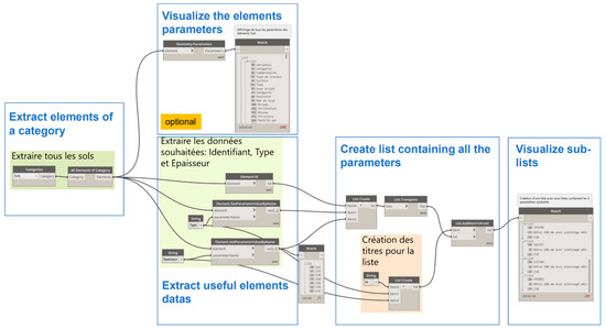
Figure 3.
Classic beginning of a Dynamo script as an example.
4.6. Step 5: Analysis of the Results
The fifth step in the methodology is to analyze the results and suggest improvements in case of non-compliance. It consists in collecting the results and interpreting them. In the end, the user wants to obtain a list of non-compliances in the model, for example, in a list with the ID of all non-compliant elements of the mockup.
5. Proof of Concept
This section describes the proof of concept of the developed method. Based on the literature and with the support of industrial partners, we use the context of mass timber offsite construction to proceed with the model checking. As noted, this type of construction requires special checks. This case study studies three different scenarios of model checking. For each model scenario, we apply the suggested method step by step. We conclude this case study with a discussion of our results.
5.1. The Context
For the context of this proof of concept, we considered the building code requirements and the requirements of two major industrial partners. We selected the specific context of the mass timber industry, an industry in full expansion today, as mass timber is a relatively recent and very promising technology. We focus on building structures constructed with CLT and glulam, both of which are prefabricated timber materials. They require specific manufacturing methods that make them entirely new building materials. Considering only constraints directly related to the design of the building, a mass timber model must comply with the following requirements from the current building codes:
- a CLT panel’s dimensions should be adapted to the manufacturing capabilities of the plant;
- a CLT panel’s dimensions should be adapted to the transport;
- a CLT panel’s width should not be more than 2550 mm (according to CSA086); and
- a CLT panel’s thickness is currently limited to 508 mm (20 in.) or less [9,12].
We consulted two industrial firms that work with such building materials. One is an engineering firm with recognized experience in designing and manufacturing mass timber products. They have their own wood processing plant. The second one is an architectural firm. Both firms design mass timber constructions, including residential buildings and other structures (stations, bridges, etc.). In particular, they worked on the design and construction of Arbora, a residential mass timber building built in Montreal in 2018. Professionals from each firm described their main challenges encountered during that 2018 project.
The Arbora project is a recent example of mass timber residential construction. The complex is composed of three buildings (phases A, B, and C). Unlike the first two phases, only Arbora phase C was planned with BIM.
Experts from the two firms told us about the main issues encountered and those related to model compliance checking. Some difficulties concerning the connections were noted: contrary to light wooden frames, the connections for mass timber are not standardized. Each connection is unique and is designed by the mass timber manufacturer. This causes compatibility issues during construction, which could have been avoided during the design stage. A second problem comes from the nesting—the step of cutting the model into CLT panels. Instead of completing it manually, it could be automated or at least optimized. The third problem involved the openings and the drilling. Designing and making the correct openings for MEP conduits in CLT panels required much back-and-forth between the two companies. For them, a verification tool that indicates in advance if a model is correctly designed in terms of MEP openings would be very useful.
Otherwise, a common structural requirement from the CLT manufacturer is to verify that the span of CLT slabs does not exceed 18 times their thickness, an important item to verify.
5.2. Case Study
Our case study consists of three different aspects to check. The first was to check that the span of the CLT slabs does not exceed 18 times its thickness (manufacturer’s geometric constraint). The second was to check the correct positioning of the drillings for MEP conduits (constraint evoked by the industry). For the third, we verified that the same CLT panel appears a minimum of 20 times in the model (prefabrication constraint).
Three digital models were at our disposal: an educative BIM model, the architectural model of Arbora, and the associated MEP model.
5.2.1. Checking Example n°1: “The Span of Each CLT Slab Should Not Exceed 18 Times Its Thickness”
For this first example, we detail the method step-by-step. The objective here is to check that the span of each CLT slab does not exceed 18 times its thickness.
- Step 1: Specification of the Checking Needs
For the first step, the checking needs have to be clearly expressed, beginning with the specificity of the project. In this first application example, the project consists of a mass timber residential building construction. At this stage of the project, the design is in the development phase. Common geometrical uses of the design have to be given and the geometric compliance of the model has to be checked. We identified the requirement to which the model must conform: a geometrical requirement whose exact rule statement is “The span of CLT slabs should not exceed 18 times their thickness”. The checking need is a geometric requirement.
- Step 2: Implementation of the BIM Environment
For the second step, the BIM environment has to be well implemented. First, we ensure that we have a workable digital mockup. The metamodel of the digital verification environment summarizes the following information:
Verification tool:
+name: Dynamo
+status: plugin tool
+operation: visual programming
+library: nodes library
mockup:
+discipline: architecture
+LOD: LOD300
+format: ifc
external_constraint:
+rule_origin: fabricant
+category: machine-interpretable
+statement: “The span of each CLT slab should not exceed 18 times its thickness”
This is a requirement expressed by the fabricant. The LOD of the model is identified with Table 2: exact quantity, shape, size, location, and orientation: LOD300. We choose Dynamo as a checking tool because it is well suited to verifying geometrical requirements. As this tool’s operation is controlled by visual programming, it is easy to extract specific information from the model for our purposes. Dynamo offers a wide flexibility in creating checking rules. In terms of interoperability, the model’s file format and the tool are compatible.
- Step 3: Analysis of the Requirements
For the third step, the requirement has to be analyzed. First, we identify the requirement’s category: Validation Checking (because the model respects or does not respect a geometric rule statement). It is a declarative clause [21], which means that the rule is computer-interpretable and, lastly, it corresponds to a conditional clause [22]. Analyzing the statement consists of identifying the physical quantities that have to be extracted, the comparison that has to be made, and the calculation that results from the statement. The statement’s analysis shows that two dimensions have to be extracted and compared: that of the span and that of the thickness of the same CLT slab. The test calculation is thus: Is the span equal to or less than 18 times the slab’s thickness? With this category of checking, automation is possible.
- Step 4: Simulation and Calculation
The simulation and the calculations are carried out in the fourth step. Considering that Dynamo has been chosen, we create an appropriate checking algorithm: a script that enables a link between the model and the calculation. This geometrical verification consists of extracting different geometrical quantities from the model (length of the frames and thickness of the floors) and then performing the test calculation. The Dynamo tool allows a verification script to be created easily, with the following steps:
- extract the slab thicknesses;
- create a thicknesses list;
- extract the span lengths;
- create a span list;
- create Python code that checks the condition for each identical level from the information in both lists; and
- return a list of non-compliances with the identifiers of the non-conforming frames and floors and their information (Level, Floor ID, Thickness, Span ID).
Figure 4 below shows the script used in verification n°1.
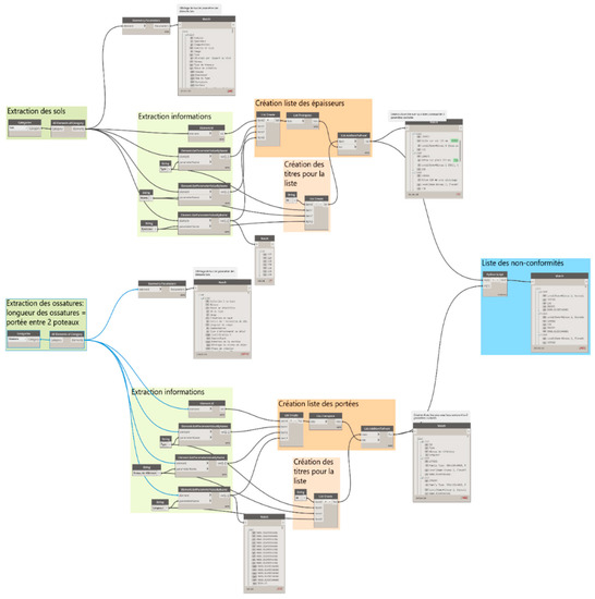
Figure 4.
The Dynamo script for verification n°1.
Dynamo allows the insertion of a Python code in the script. The code used allows us—with different lists—to extract and return the non-conformance information in a final list, as presented in Figure 5.
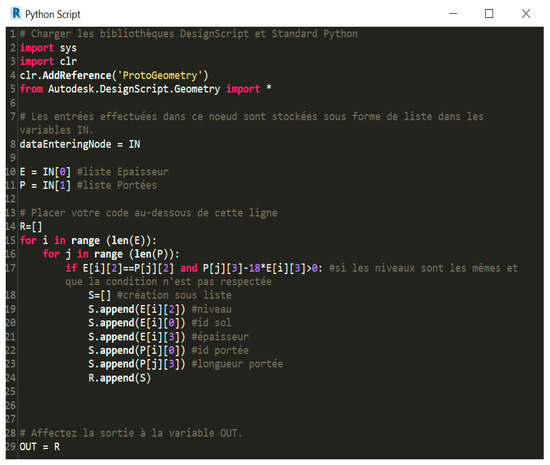
Figure 5.
Python code for verification n°1.
- Step 5: Analysis of the Results
The results are analyzed in the fifth step. Several difficulties were found with the Arbora model: an error message was systematically returned. This is an error concerning a type not supported in the Python code. The information from the properties of the elements (Soils, Frames) was not interpretable by the calculation. Type problems with P[j][3] and E[i][3] indicated that IronPython.Runtime.Types.Python was not recognized as a number with which to perform a calculation. On the contrary, the Dynamo script worked correctly with the BIM educative model; we only had to fill in some missing floor thicknesses at the beginning. At the end, this first check was completed and we conclude that there are some slabs that do not comply with the requirement studied.
For this checking n°1, the difficulties encountered were:
- Arbora model: A type of information was not readable by the Dynamo script (type: IronPython.Runtime.Types.Python);
- BIM educative model: A mockup with missing, inaccessible, or non-indexed information (thickness of the floor).
These obstacles to verification only concerned the digital model and its properties.
5.2.2. Checking Example n°2: “Drillings for MEP Conduits Must Be Correctly Positioned”
For this second application example, we again describe how we proceed step-by-step according to the developed method. This example aims to check the drillings and their correct positioning.
- Step 1: Specification of the Checking Needs
In this second application example, the project consists of a mass timber residential building construction. At this stage of the project, the design is at the end of the development phase, and so the focus is on more precise details. We identified the requirement to which the model must conform: a geometrical requirement whose exact rule statement is “Drillings and openings for MEP conduits must be correctly positioned”. The checking need is a positioning and geometric requirement.
- Step 2: Implementation of the BIM Environment
For the second step, the BIM environment has to be well implemented. First, we ensure that we have a workable digital mockup: the architectural model of Arbora. The metamodel started to be used but soon a major problem was noticed: the architectural model does not present any drillings for connection or openings for MEP conduits. If something is not modeled digitally, it is impossible to proceed with any kind of verification about the digital element. As the required information is not modeled, this verification cannot be completed.
For checking n°2, the difficulties encountered were:
- Arbora model: Openings are not modeled.
5.2.3. Checking Example n°3: “The Same CLT Panel Must Appear a Minimum of 20 Times in the Model”
As with the other two, we detail how we implement the developed method for this application example. The objective here is to check that the same type of CLT panel is present a minimum of 20 times in the model.
- Step 1: Specification of the Checking Needs
In this third application example, the project consists of a mass timber residential building construction. At this stage of the project, the design is in the development phase, and so basic rules about the geometry and the elements’ presence must be followed. We identified the requirement to which the model must conform: a basic rule concerning the presence of elements whose exact rule statement is “The same CLT panel must appear a minimum of 20 times in the model”. The checking need consists of counting the number of occurrences of an element in the whole model.
- Step 2: Implementation of the BIM Environment
For the second step, the BIM environment has to be well implemented. First, we ensure that we have a workable digital mockup: the architectural model of Arbora. The metamodel of the digital verification environment summarizes the following information:
Verification tool:
+name: Dynamo
+status: plugin tool
+operation: visual programming
+library: nodes library
mockup:
+discipline: architecture
+LOD: LOD300
+format: ifc
external_constraint:
+rule_origin: other
+category: machine-interpretable
+statement: “The same CLT panel must appear a minimum of 20 times in the model”.
This is a requirement expressed by the fabricant. The LOD of the model, LOD300, has been identified by Table 2. We choose Dynamo as a checking tool because it is well suited to verify quantity requirements, and it offers a wide flexibility due to visual programming. In terms of interoperability, we verified that the model file format and the tool are compatible.
- Step 3: Analysis of the Requirements
For the third step, the requirements have to be analyzed. First, we identify the requirement’s category: Model Content Checking. The statement’s analysis shows that each element with type “DALLE CLT 175 mm” must be extracted and then counted. The test calculation is thus: Is the same CLT panel model present at least 20 times in the model? With this category of checking, automation is possible.
- Step 4: Simulation and Calculation
The simulation and the calculations are carried out in the fourth step. Considering that Dynamo has been chosen, we create an appropriate checking algorithm: a script that can create a link between the model and the calculation. We focus on the CLT slab with type number 2517108 and 175 mm thickness, which type is: “DALLE CLT 175 mm”.
- extract the soils;
- create a list of ID and Type of soils;
- Python code that filters all the soils by Type;
- return a list of all soils of the desired Type DALLE CLT 175 mm (→length of list).
We create a Dynamo visual programming script (see Figure 6). The first step is the extraction of all soils. From that category, we extract their ID and Type specified in the properties and put all the data into lists. Next, a Python script has to be written: it filters all the soils by Type. The output lists all the soils with the following Type: DALLE CLT 175 mm, 2517108. The length of the list thus directly indicates the number of CLT slabs.
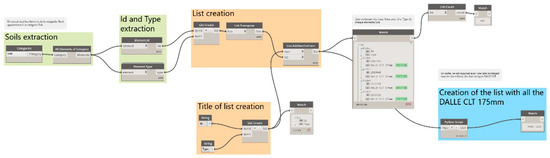
Figure 6.
Dynamo script for verification n°3.
However, the scripts returned an empty list. One difficulty is to identify the interpretable name of S[i][1]. Many tests with other parameters were conducted and proved that the Python scripts are correct. The issue seems to come from the name of the Type. The Type entered in the soil’s properties is “DALLE CLT 175 mm” with the identifier 2517108. This name does not appear to be interpretable as a type by the program. Neither the name “DALLE CLT 175 mm” nor the identifier 2517108 is interpretable by the code (see Figure 7). This has been identified as is a problem about the information type. Even though it is a number, it is not a number that the machine can interpret.
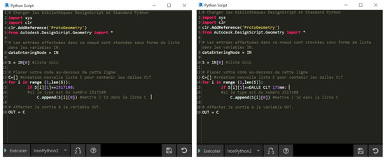
Figure 7.
Python code for verification n°3.
For checking n°3, the difficulties encountered were:
- Arbora model: Unidentifiable soil type.
6. Discussion and Conclusions
The study aims to offer AEC professionals a method that synthesizes the stages of the model-checking process. Ideally, we want the user to be able to use this method to assess whether a design complies with the manufacturing capability, as a requirement among others, at the mass timber plant. This work aims to make model checking accessible to everyone and to show the possibilities and obstacles related to this task.
While most studies have focused on automated rule checking and code compliance checking, we cover a broad set of model checks based on the use of BIM technology. Our approach brings new elements into the field: we have detailed the requirements needed to proceed with model checking, and we contributed generally to the democratization of the use of mass timber as a construction material, as verified in a case study. The method synthesizes the options and possibilities offered by the BIM verification of the models, characterizes the conditions to automate the task, and facilitates the user in the implementation of the digital environment. It allows users, whether they are beginners or advanced, to anticipate and more easily anticipate the process of BIM-based model checking.
We compared the performance of different verification software, explored the conditions of application of the different types of verification, and provided concrete tools to carry out these verifications at each step. Through our applications, we proved that the tools are powerful and allow us to perform verifications based on the BIM approach. In addition, this work has brought something new to the field of mass timber construction by analyzing the design issues related to this material during the design stage and the model-checking stage. We used Dynamo primarily for our verification. Due to its visual programming mode of operation, and thus its great flexibility to create checking rules, we found it to be the most suitable tool for performing our verifications. However, some difficulties appeared.
Indeed, some problems appeared when we attempted to apply the method in the case studies. We had a problem with an impossible interpretation of the data, which meant that our checks could not be completed. For the application cases, it was expected that the three simple checks could be conducted completely, and we thought that the data would be more easily usable. We did not expect to have to deal with data issues that could not be interpreted by the verification software. We were surprised by the recurrent problems of incorrectly filled in or missing information in the model. Both of these issues showed how BIM requires first and foremost having a great digital mockup. It has to contain all the necessary information, and the information must be usable and interpretable by the checking software. Many times, the information in the model was not in the format required by the software. It was not possible to complete the verification because the calculation via the software could not be carried out. However, the three case studies demonstrated that the five-step method leads to a conclusive model-checking process. In fact, we attempted to apply the whole method using the suggested tools, and it was possible to understand why some case studies were not successful.
Our research has a few limitations. First, our interviews and case studies focused on a single mass timber project, which is not representative. We also had only one mass timber model at our disposal, which limited the diversification of the case studies and the comparison. Nevertheless, our contribution to the research consisted in proposing a general method to study model conformity according to requirements.
We note from this research that the software packages dedicated to model checking are numerous and promising. They allow for many possibilities and have a great potential to make the model-checking step worthwhile. However, having powerful software without usable models is useless. To fully benefit from these tools, the digital mockups have to be very well modeled and their data rigorously updated and verified. While our work has been confronted with many obstacles, we see this research on BIM-based model checking as an exploration of this use of BIM to perform model checking. In total, we have addressed several aspects of model checking (synthesis of possible verifications, automation of certain verifications, comparison of verification software, etc.). BIM verification tools have been shown to help verify multiple requirements models, not just those from building codes. For example, the requirements related to the manufacturing capacity of a plant can be tested. Some other requirements from other checking categories can also be considered. For the category Model Content Checking, we can verify if there are glulam beams with x–y sections in the model. For the category Smart Environment Checking, a model which fits and adapts itself in suggesting a mass timber building with a unique model of CLT panels and a unique model of glulam beams could be an interesting aspect.
For future work, it would be interesting to study in detail the verification of prefabricated 3D modular models. Concerning mass timber in particular, it would also be interesting to study the design and verification issues encountered on other mass timber projects, for example.
This work will allow us to make recommendations to the industry. It is very important to specify the intended uses of digital models in the BIM plan. The project should be planned around the model and therefore designed accordingly so that it can be able to operate it.
Author Contributions
Conceptualization, C.P., C.B. and P.B.; methodology, C.P. and C.B.; software, C.B.; validation C.B. and P.B.; formal analysis, C.P. and C.B.; investigation, C.P.; resources, C.B. and P.B.; data curation, C.P.; writing—original draft preparation, C.P.; writing—review and editing, C.P., C.B. and P.B.; visualization, C.P.; supervision, C.B. and P.B.; project administration, C.P. and C.B.; funding acquisition, P.B. All authors have read and agreed to the published version of the manuscript.
Funding
The authors are grateful to Natural Sciences and Engineering Research Council of Canada for the financial support through its IRC and CRD programs (IRCPJ 461745-18 and RDCPJ 524504-18) as well as the industrial partners of the NSERC industrial chair on eco-responsible wood construction (CIRCERB).
Conflicts of Interest
The authors declare no conflict of interest.
References
- S.C. Government of Canada. The Daily—Sawmill Industry in Canada: 15 Years in Review. 2022. Available online: https://www150.statcan.gc.ca/n1/daily-quotidien/220711/dq220711b-eng.htm (accessed on 24 April 2023).
- Ressources Naturelles et Forêts, Chiffres-Clés du Québec Forestier—Édition 2023. 2023. Available online: https://mffp.gouv.qc.ca/nos-publications/chiffres-cles-quebec-forestier/ (accessed on 11 April 2023).
- United Nations. Forest Products Annual Market Review 2019–2020; United Nations: Geneva, Switzerland, 2021. [Google Scholar]
- McKinsey & Company. Modular Construction: From Projects to Products. 2019. Available online: https://www.mckinsey.com/business-functions/operations/our-insights/modular-construction-from-projects-to-products (accessed on 7 April 2022).
- Smith, R.E.; Quale, J.D. Offsite Architecture: Constructing the Future; Routledge: London, UK; Taylor & Francis Group: New York, NY, USA, 2017. [Google Scholar]
- Wilson, J. Design for Modular Construction: An Introduction for Architects; The American Institute of Architects: Washington, DC, USA, 2020. [Google Scholar]
- Churkina, G.; Organschi, A.; Reyer, C.P.O.; Ruff, A.; Vinke, K.; Liu, Z.; Reck, B.K.; Graedel, T.E.; Schellnhuber, H.J. Buildings as a global carbon sink. Nat. Sustain. 2020, 3, 269–276. [Google Scholar] [CrossRef]
- Commission Canadienne des Codes du Bâtiment et de Prévention des Incendies. Code National du Bâtiment—Canada 2020. 2022. Available online: http://central.bac-lac.gc.ca/.redirect?app=damspub&id=9868f8a0-3afc-481b-b65e-127d0eaa8b6f (accessed on 22 June 2022).
- ANSI APA PRG320; Standard for Performance-Rated Cross-Laminated Timber. American National Standards Institute: Washington, DC, USA, 2018.
- CAN/CSA-O122-16 (R2021); Structural Glued-Laminated Timber. CSA Group: Toronto, ON, Canada, 2016.
- Pelletier, A.; Lessard, N.; Gagnon, S.; Dagenais, C. Bâtiments de Construction Massive en Bois Encapsulé d’au Plus 12 étages—Directives et Guide Explicatif—Version Révisée 2022. 2022; p. 100. Available online: https://www.rbq.gouv.qc.ca/domaines-dintervention/batiment/les-mesures-equivalentes-et-les-mesures-differentes/construction-massive-en-bois/ (accessed on 11 April 2023).
- Karacabeyli, E.; Gagnon, S. Manuel Canadien sur le CLT; FPInnovations: Pointe-Claire, QC, Canada, 2019; Volume 1. [Google Scholar]
- Karacabeyli, E.; Lum, C. Technical Guide for the Design and Construction of Tall Wood Buildings in Canada; FPInnovations: Pointe-Claire, QC, Canada, 2022; Available online: https://web.fpinnovations.ca/fr/tallwood/ (accessed on 10 May 2022).
- Alfieri, E.; Seghezzi, E.; Sauchelli, M.; Di Giuda, G.M.; Masera, G. A BIM-based approach for DfMA in building construction: Framework and first results on an Italian case study. Arch. Eng. Des. Manag. 2020, 16, 247–269. [Google Scholar] [CrossRef]
- Hjelseth, E. BIM-based model checking (BMC). In Building Information Modeling: Applications and Practices; Issa, R.R.A., Olbina, S., Eds.; American Society of Civil Engineers: Reston, VA, USA, 2015. [Google Scholar]
- Issa, R.R.A.; Olbina, S. Building Information Modeling: Applications and Practices; American Society of Civil Engineers: Reston, VA, USA, 2015. [Google Scholar] [CrossRef]
- Ben Mahmoud, B.; Lehoux, N.; Blanchet, P.; Cloutier, C. Barriers, Strategies, and Best Practices for BIM Adoption in Quebec Prefabrication Small and Medium-Sized Enterprises (SMEs). Buildings 2022, 12, 390. [Google Scholar] [CrossRef]
- Hjelseth, E. Classification of BIM-based model checking concepts. J. Inf. Technol. Constr. 2016, 21, 354–369. [Google Scholar]
- Messner, J.; Anumaba, C.; Dubler, C.; Goodman, S. BIM Project Execution Planning Guide, Version 3.0; Penn State: State College, PA, USA, 2021. [Google Scholar]
- Succar, B. Building information modelling framework: A research and delivery foundation for industry stakeholders. Autom. Constr. 2009, 18, 357–375. [Google Scholar] [CrossRef]
- Malsane, S.; Matthews, J.; Lockley, S.; Love, P.E.; Greenwood, D. Development of an object model for automated compliance checking. Autom. Constr. 2015, 49, 51–58. [Google Scholar] [CrossRef]
- Nawari, N.O. Building Information Modeling: Automated Code Checking and Compliance Processes; CRC Press: Boca Raton, FL, USA, 2018. [Google Scholar] [CrossRef]
- Kim, H.; Lee, J.-K.; Shin, J.; Choi, J. BIM-Supported Visual Language to Define Building Design Regulations. In Proceedings of the CAADRIA 2017: Protocols, Flows, and Glitches, Suzhou, China, 5–8 April 2017; pp. 603–612. [Google Scholar] [CrossRef]
- Nawari, N.O. A Generalized Adaptive Framework (GAF) for Automating Code Compliance Checking. Buildings 2019, 9, 86. [Google Scholar] [CrossRef]
- Preidel, C.; Borrmann, A. Automated Code Compliance Checking Based on a Visual Language and Building Information Modeling. In Proceedings of the 32nd ISARC, Oulu, Finland, 15–18 June 2015. [Google Scholar] [CrossRef]
- Eastman, C.; Lee, J.-M.; Jeong, Y.-S.; Lee, J.-K. Automatic rule-based checking of building designs. Autom. Constr. 2009, 18, 1011–1033. [Google Scholar] [CrossRef]
- Kincelova, K.; Boton, C.; Blanchet, P.; Dagenais, C. Fire Safety in Tall Timber Building: A BIM-Based Automated Code-Checking Approach. Buildings 2020, 10, 121. [Google Scholar] [CrossRef]
- Kincelova, K.; Boton, C.; Blanchet, P.; Dagenais, C. BIM-based code compliance checking for fire safety in timber buildings: A comparison of existing tools. In Proceedings of the 7th International Construction Specialty: CSCE Annual Conference: Growing with youth—Croître Avec Les Jeunes, Laval, QC, Canada, 12–15 June 2019. [Google Scholar]
- Bedrick, J.; Ikerd, W.; Reinhardt, J. Level of Development (LOD) Specification Part I & Commentary; BIM Forum: Singapore, 2020. [Google Scholar]


Disclaimer/Publisher’s Note: The statements, opinions and data contained in all publications are solely those of the individual author(s) and contributor(s) and not of MDPI and/or the editor(s). MDPI and/or the editor(s) disclaim responsibility for any injury to people or property resulting from any ideas, methods, instructions or products referred to in the content. |
© 2023 by the authors. Licensee MDPI, Basel, Switzerland. This article is an open access article distributed under the terms and conditions of the Creative Commons Attribution (CC BY) license (https://creativecommons.org/licenses/by/4.0/).