Article

Changes in Clay Hollow Block Geometry for Energy Efficiency Benefits—Thermal Simulation for Brazil

by
Ivo Almino Gondim
1,
Hipólito Sousa
1 and
Alexandre Bertini
2,*
1
Construction Institute, CONSTRUCT/GEQUALTEC, Faculty of Engineering, Porto University, 4200-465 Porto, Portugal
2
Department of Structural Engineering and Building, Federal University of Ceará, Campus PICI, Fortaleza 60455-760, Brazil
*
Author to whom correspondence should be addressed.
Buildings 2023, 13(7), 1594; https://doi.org/10.3390/buildings13071594
Submission received: 9 May 2023 / Revised: 17 June 2023 / Accepted: 19 June 2023 / Published: 24 June 2023
(This article belongs to the Section Building Energy, Physics, Environment, and Systems)

Abstract

:
Masonry, which constitutes a large area of many buildings’ envelopes, represents important thermal performance and energy consumption functions. Clay hollow block geometry can influence these results. In this sense, this work aims to numerically evaluate the thermal properties and energy efficiency improvement provided by new geometries of clay blocks in the Brazilian context. Two commercial block geometries were selected, and new internal void geometries were proposed, maintaining approximately the same percentage of voids. The new formats were submitted to numerical simulation using Abaqus/CAE 2020 software, to obtain their thermal resistance. Finally, an energy simulation study was carried out in three housing typologies located in two Brazilian cities, Curitiba and Fortaleza, using EnergyPlus 9.2 software. Geometric changes resulted in reductions in thermal transmittance values of greater than 30% for the blocks and 20% for the walls. Regarding possible energy reduction, the study demonstrated that there is a non-significant reduction in values for periods of higher temperature (hottest month), in the evaluated schedule use, as well as a potential for savings (34% in the apartment typology for the coldest month) at lower temperatures. Findings of this study serve as a reference to discuss improvements in clay hollow brick geometry regarding energy efficiency and thermal comfort in the Brazilian context.

1. Introduction

Energy consumption has increased significantly in buildings over the past few decades. According to data from [1], total electricity consumption in the world reached 22,848 TWh in 2019, representing an increase of 1.7% compared to 2018. The residential and commercial sectors, including public services, represent approximately 26.6% and 21.8% of this consumption. The growth of these sectors since 1974 represents a multiplication factor of greater than five.
Construction systems with better thermal properties are important for user comfort requirements and to achieve energy efficiency improvement. Thermal comfort requirements are related to ISO 7730 [2], the ASHRAE standard 55 [3], and, in Brazil, the NBR 15220 [4,5] and NBR 15575 [6] standards. Through climate zoning of the Brazilian map, different requirements and strategies are established for each zone. Besides this, there are different requirements for different parts of buildings, such as external walls and roofs. Regarding external envelope thermal performance, criteria consider properties such as thermal external walls’ transmittance and thermal capacity, ventilation area, and translucid surface area.
In this context, one of the ways to improve thermal comfort and energy efficiency involves external masonry blocks with better thermal properties. A limiting factor in this decision is the potential increase in costs. The hollow clay block is one of the most widespread building components in the world, and is currently one of the main construction systems for the execution of external masonry. The cost of this block is strongly influenced by the consumption of clay during manufacture, evaluated by the percentage of voids, energy required for firing, and transportation.
Concerning thermal comfort, many studies have assessed the improvement of thermal blocks’ properties, involving composition. Thermal transmittance improvements in concrete bricks were achieved through the addition of tire rubber residues, with improvement in thermal performance ranging between 5 and 11% depending on the amount added [7]. In another study, hollow concrete masonry blocks made of low-strength self-compacting concrete with recycled crushed brick and ground polystyrene as an aggregate showed reduced transmittance when compared to hollow concrete blocks and hollow clay blocks [8]. In clay bricks, the addition of the residue from the industrial processing of recycled paper was tested to produce porous and lightweight bricks with reduced thermal conductivity, provided by the lower thermal conductivity of the material, presenting acceptable compressive strength [9]. In another study [10], the addition of expanded vermiculite in porous clay bricks was able to reduce thermal conductivity by 32%. Thermal insulation performance was also improved in other research [11] by adding pumice and expanded vermiculite into clay bricks when compared to normal clay bricks. In this context, the addition of a recycled insertion into new block formulations can contribute to reducing environmental impact and increasing thermal features.
However, even with the benefits pointed out, there are also ways to obtain improvements by acting on the geometry of the units, without the need to modify the raw material, which is the objective of this work. For this purpose, the thermal performance of the same buildings using normal or improved ceramic blocks is compared.
Different studies used computer simulation processes to obtain the effect of the adoption of different construction systems on the energy consumption of buildings. An up-to-date hollow brick clay was found to be a suitable construction material for passive family houses in Central European countries after computational analysis of thermal performance [12]. In another study, thermal dynamic analyses were performed through numerical simulations in order to analyze the influence of enclosure masonry walls on the energy consumption of buildings without heating, ventilation, and air conditioning (HVAC) systems installed [13]. Computational thermal analysis was conducted to study the effect of materials with different thermal insulation and thermal mass on thermal comfort and energy savings of three types of building, two single-family houses and one apartment, in a Mediterranean climate [14]. A simulation study was carried out to evaluate how a lightweight phase-change wall of a passive solar room (Trombe form) improves the indoor thermal environment in winter for a house [15]. In another simulation study, a physical model of a room (Trombe form) with a light phase-change wall was built in simulation software, and the correctness of the model was verified through a comparison experiment. An important point of simulation analysis is defining a temperature range for thermal comfort. The predicted mean vote (PMV) is an index that predicts the mean value of the votes of a group of persons on a thermal sensation scale [3]. It is based on the heat balance of the human body and is influenced by environmental conditions. It is typically used to determine a thermal comfort temperature range and changes according to location.
The impact on thermal properties related to hollow block geometry has been the subject of different studies [16,17,18,19,20,21], in aspects involving hole accounting, thicknesses of internal walls, and thermal bridge reduction. Applying these concepts in standardized and commercial masonry blocks in Brazil may represent an improvement in buildings’ thermal and energy efficiency. Brazil is characterized by different climate zones. Building cooling is the most challenging issue in northeast cities, and both cooling and heating are required in many southern cities.
In this sense, this study aims to numerically evaluate how thermal properties are improved by new clay block geometry and evaluate the resulting energy consumption impact in a building. The new geometry was simulated in the Brazilian context, with no significant increase in clay consumption compared to the reference block. As a premise, it was considered that clay consumption and mechanical resistance are associated with the percentage of voids.
The next section presents the heat transfer and thermal properties of hollow blocks. Section 3 provides the methods used, and Section 4 gives the results and discussion. In Section 5, findings and implications are presented, as well as limitations, suggestions for future work, and applications.

2. Thermal Analysis in Building Masonries

Heat Transfer and Thermal Properties of Hollow Blocks

Heat flow inside construction elements occurs through three types of combined mechanisms: conduction, convection, and radiation. Conduction consists of a heat transfer mechanism in solid materials. However, it does not fully explain heat transfer between building elements. There are two ways to analyze this. First, temperatures on element surfaces and their adjacent elements (air or objects) are different. If air is displaying a temperature gradient, other mechanisms also exist—for air, these mechanisms are convection and radiation. Second, even when only conduction is present, for example on a solid wall, with a temperature difference between two faces, the temperatures inside the wall will eventually equalize [22].
When these phenomena are considered in projects, thermal properties are required. Some of the main ones, mentioned in ISO 6946 [23], are: thermal conductivity, inherent to the material used and expressed in W/(m·k); thermal resistance of building elements and components; and thermal transmittance (U value). If thermal conductivity is provided, thermal resistance (R) can be obtained using Equation (1):
R = d λ ,
where d is the thickness of the material layer in the component and λ is the design thermal conductivity of the material.
Total thermal resistance, Rtot, from a plane-building component with perpendicular layers related to heat flux, must be calculated by Equation (2):
R t o t = R s i + R 1 + R 2 + + R n + R s e ,
where Rsi (m2 K/W) and Rse (m2 K/W) are the internal and external surface resistances, and R1, R2, …, Rn are the design thermal resistances of each layer. Thermal transmittance (U) is given by (3):
U = 1 R t o t ,
The existence of layers can significantly influence the thermal properties of a building wall. Component selection, hollow block geometry, grout use, mortar type, contact between blocks and mortar, angles, joint geometry, insulation and thermal bridges, design considerations, and material choice are some of the variables that can influence resistance and thermal transmittance [24].
A systematic review conducted by [20] revealed that building components can significantly affect the reduction of energy use associated with a building. Regarding the improvement of thermal efficiency in hollow blocks, some investigation conclusions were obtained:
  • Block configurations are designed by optimizing hollow geometries such as void width, void depth, and the total number of voids. The thermal resistance of blocks can be enhanced by changing the aforesaid parameters;
  • The filling of hollow block cavities with insulation materials has a high potential to reduce effective conductivity;
  • The lower the coefficient of the thermal conductivity of insulation materials, the stronger the insulation and the higher the cost of the hollow block;
  • Engineers should consider developing low-energy residential or office buildings with the use of optimum hollow blocks. Moreover, this improvement is affordable, as there is no need for substantial expenditure on the construction of block models.
In this context, the geometry of masonry components has a relevant influence on the thermal resistance of masonry. The EN 1745 standard [25] considers the following to be the theoretical basis for the main geometric influences on thermal resistance: the number of void rows; thickness of material webs between the voids; staggered or ‘in-line’ voids; and shape of voids. The different ways of increasing thermal resistance according to these parameters, and others mentioned in the scientific literature for the masonry unit, are presented in Table 1.
Given the simplicity of rectangular hollow geometry and low thermal difference from other formats, this work considers the rectangular void model as the most suitable for conducting the first stage of studies on the improvement of thermal properties from a reference model.
In Brazil, masonry clay blocks are standardized by NBR 15270 [28]. The blocks can consist of masonry in the following functions: sealing masonry, in which masonry is not admitted as a participant in the structure; and structural masonry, admitted as a participant in the structure. In this work, case geometries involving structural masonry with hollow blocks will be studied. For this model, the minimum resistance requirement is 4.0 MPa (EST40). For this resistance, there is a minimum thickness requirement of 7.0 mm for the external shell of the block and 6.0 mm for the internal web. If the resistance class is higher, the shell must have a minimum thickness of 8.0 mm and a web of 7.0 mm.

3. Materials and Methods

Steps involved in this study include the definition of the new block geometries to be used, and then two simulation techniques: a numerical study, through finite element applications with the aid of Abaqus software [29], to obtain the thermal transmittance of new ceramic block geometries; and an energy efficiency simulation in a dwelling, using EnergyPlus software [30].

3.1. Changing Hollow Geometry Block in the Brazilian Context

For the purpose of thermal analysis, it was initially necessary to define the models of blocks to be analyzed. As reference models, two models of ceramic blocks for structural masonry were chosen, obtained from a supplier commercial catalogue which meets the Brazilian standard ABNT 15270:2017. These blocks, with 140 mm thickness, are classified into mechanical resistance categories EST40 and EST60. These categories represent some of the most applicable models for housing buildings. Figure 1 and Table 2 show the characteristics of the blocks, according to the supplier.
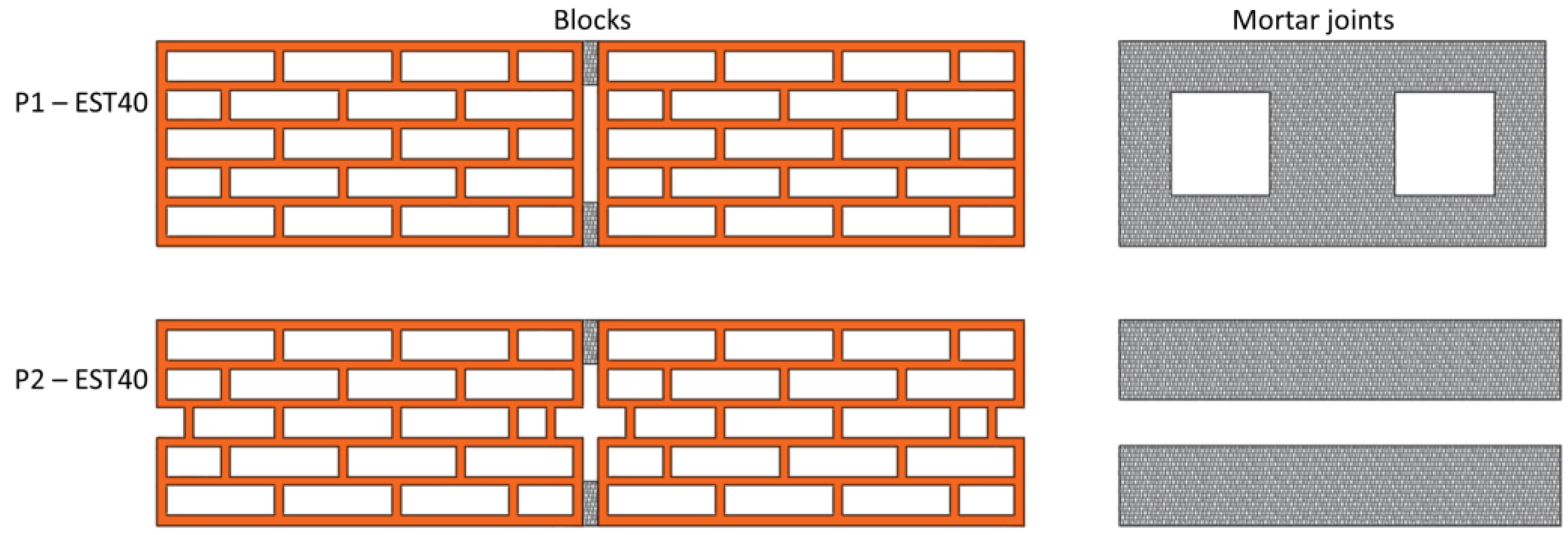
Regarding geometry change, two steps were adopted. In the first step, for each reference masonry unit, the following premises were established for the prototypes of new geometries, designated as P1-EST40 and P1-EST60:
  • In the case of block P1-EST40, the minimum wall thickness considered was 7 mm for the external shell and 6 mm for the internal web. In the case of block P1-EST60, the minimum wall thickness considered was 8 mm for the shell and 7 mm for the web. These changes take into account the minimum measures provided by the NBR 15270:2017 standard for clay blocks with vertical voids.
  • This geometry sought to increase the number of void rows, respecting the minimum thickness requirements, without significant changes in the relationship between the net area and the gross area of the block. This measure sought to avoid significant cost increases due to higher material consumption.
  • Web walls perpendicular to the direction of the masonry were established to provide stability in block resistance but were not evaluated in this work. These walls were arranged without continuity between void rows, to reduce the thermal bridge effect.
  • The mortar distribution was maintained using the same format as the reference block.
  • In the second stage, the following changes were made:
  • A discontinuity was introduced into the side shell of the block, to reduce the thermal bridge effect;
  • Horizontal mortar distribution was altered to avoid a thermal bridge through the mortar;
  • The vertical joint of the mortar filled the entire height in all cases, with 1 cm thickness and 3 cm depth.
Results are presented in Figure 2 for category EST 40, and in Figure 3 for category EST 60.
A comparison between the properties of the blocks, with both the common geometry and the new geometries, including the relationship between net area and gross area, is presented in Table 3. Masonry unit dimensions were not changed.

3.2. Numerical Simulation Procedure Using Finite Elements

Before conducting a masonry unit simulation, which is one of the objects of study in this work, validation was performed in Abaqus software with an example model provided by annex D in the EN 1745 standard [25], adapted into a three-dimensional format, with a height of 20 cm. Results (0.5699 W/m2·K) showed a 0.8% difference compared to the U value mentioned (0.5656 W/m2·K) in the standard calculation, representing acceptable tolerance.
For the simulation procedure, the coefficients for thermal conductivity were specified: λ = 1.05 W/(m2. °C) and λ = 1.15 W/(m2.°C), respectively. These coefficients were based on NBR 15220 [5]. In the specific case of ceramic material, the value considers a specific mass between 1800 and 2000 kg/m3.
For air voids present in the masonry, where heat transmission phenomena occur through conduction, convection, and radiation, equivalent thermal conductivity coefficients were adopted by the procedure described in Standard EN ISO 6946 [23]. A temperature of 20 °C was adopted to obtain the black body radiation coefficient.
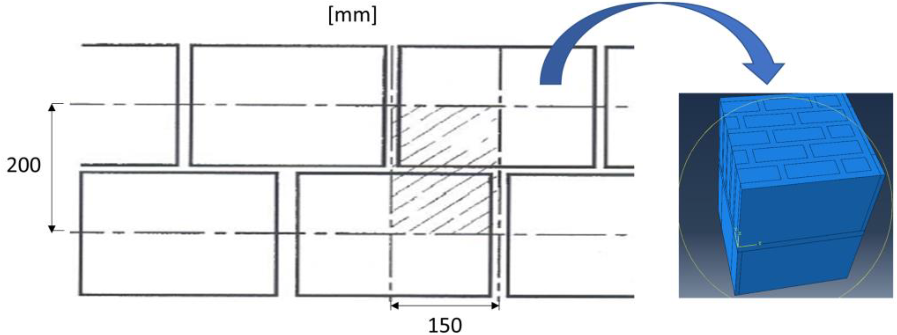
With the help of Abaqus software, three-dimensional modelling was established using a repetitive unit, as exemplified in Figure 4.
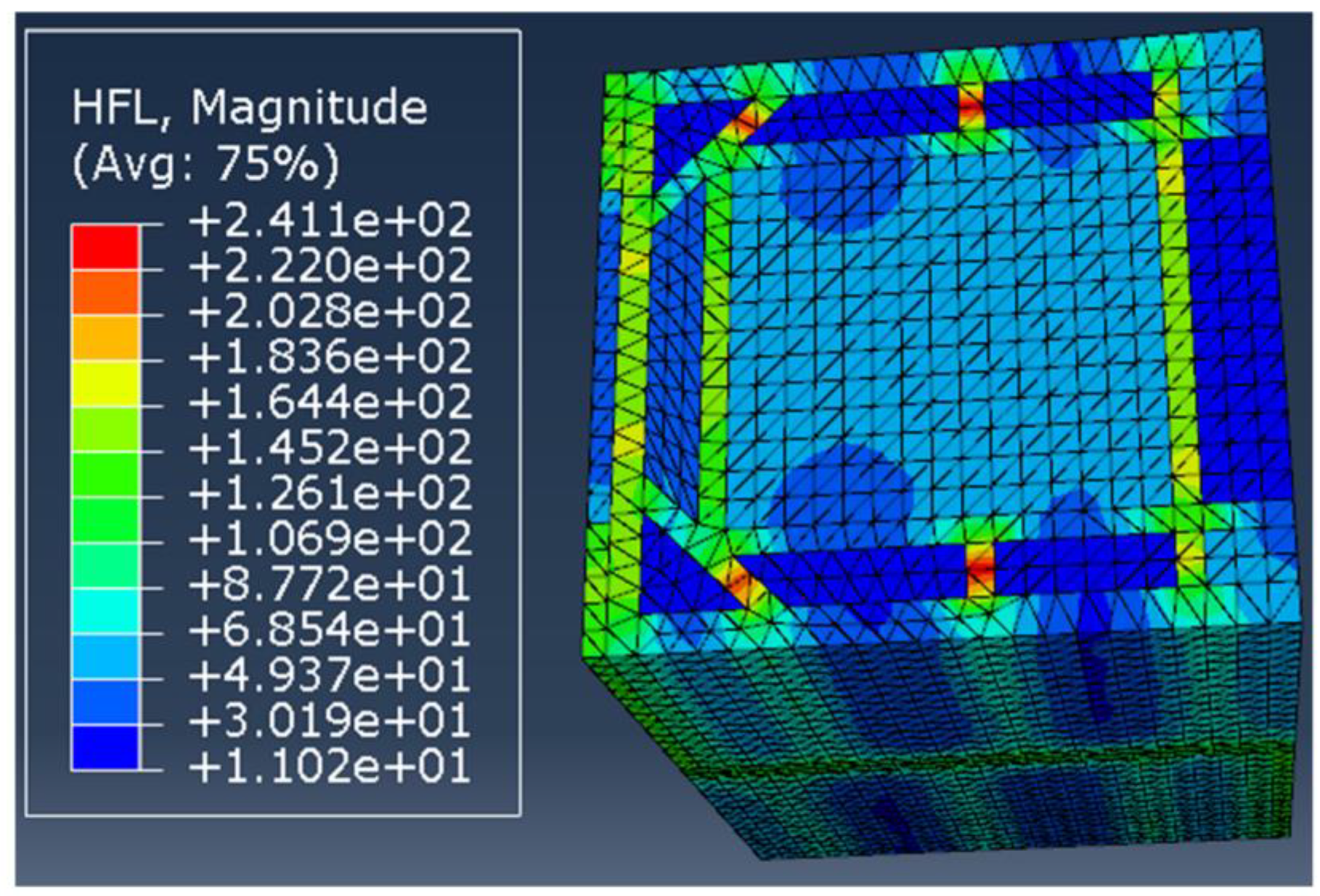
A temperature gradient between two faces was established at 20 °C. It was applied on one of the faces at 40 °C and on the other at 20 °C, to generate a heat flux for obtaining masonry thermal transmittance in the selected block. To discretize masonry units, including voids and joints, a mesh with triangular tetrahedral elements was adopted. Using the software, it was possible to obtain the heat flow in the masonry stretch. Figure 5 illustrates heat flow through the EST40 block in the software, displaying a higher value in the stretches of internal walls perpendicular to the direction of the masonry, and the effect of thermal bridges.
The thermal transmission coefficient was obtained by expression (4):
U = F l T L h ,
where Fl represents the sum of the heat flow reaction in one of the faces submitted to the flow, obtained in the software through the sum of the heat flow reaction; ∆T represents the temperature difference (20 °C in this work); and Lh represents the area of the face obtained by multiplying measurements (0.15 m × 0.2 m in the standard unit of this work).

3.3. Energy Efficiency Numerical Analysis in Housing Buildings

The specific objective of this stage was to analyze the energy requirements (energy consumption to maintain indoor comfort temperatures) of rooms where walls were built with different specifications of masonry units: EST40 and P1-EST40.
Simulations were performed using EnergyPlus software, version 9.2. EnergyPlus has three basic components: a simulation manager, a heat and mass balance simulation module, and a building systems simulation module [31]. The software allows energy simulation for buildings, involving consumption for heating, cooling, lighting, water use, and other uses. Two types of file are usually used as input data: an IDF extension file, which includes the description of the building model as well as a building occupancy pattern schedule and building and material specifications, among other information; and an EPW extension file, which corresponds to the climatic data of the simulation location [30].
One of the main challenges of a project involves reducing the energy requirement for heating or cooling, to maintain temperature at thermal comfort during use. Strategies involving envelope thermal insulation are one way to improve the efficiency of buildings in most locations.
The simulation model adopted in this work followed an adaptation of the reference model obtained by [32], through the clustering process of a sample of housing unit projects located in the city of Florianópolis, Brazil. The model adopted corresponds to a house of 37 m2, comprising two bedrooms, one bathroom, and combined living room and kitchen, as shown in Figure 6.
For a better representative analysis, considering different weather conditions, two Brazilian cities were chosen for this simulation: Curitiba and Fortaleza. The climatic files TRY (Test Reference Year) were used in simulations, which represent a single year to be more representative and present. A summary of weather conditions for Fortaleza and Curitiba from climatic files is presented in Table 4.
Evaluation of the housing unit considered occupation and use by a family of four. The main occupation characteristics adopted were:
  • Lighting power of 100 W for the living room/kitchen, and 60 W for each room;
  • Metabolic rate of 108 W/person in the living room and 81 W/person in the bedrooms;
  • Equipment power level of 120 W for the living room/kitchen;
  • Comfort temperature between 18 °C and 26 °C, obtained by [32], determined according to the ASHRAE [3];
  • A ventilation model configured by the airflow network object, present in the EnergyPlus software, which considers natural ventilation according to the climatic file;
  • No air renewal between roof and ceiling (slab);
  • Openings (glass windows) corresponding to 5.61% of the area of the south façade, 7.5% of the area of the west façade, 5.61% of the north façade area, and 9.77% of the east façade area.
Room occupancy pattern, electrical and artificial lighting equipment use pattern, and operation pattern of window openings are presented in Figure 7, Figure 8, Figure 9 and Figure 10.
In relation to the construction pattern, Table 5 presents its main characteristics.
For this, the following configurations and adaptations were chosen for the houses:
  • House 1: two-bedroom house with flat roof and glass windows;
  • House 2: two-bedroom house with ceramic tile roof and glass windows;
  • Apartment: two-bedroom apartment with glass windows and two façades.

4. Results and Discussion

4.1. Thermal Transmittance (U)

The results of the thermal transmittance, obtained after the described procedures, are presented in Table 6. It can be observed that the reduction pertaining to the masonry units ranged from 31.7% to 36.1% in geometric changes. When considering a wall with mortar coating of 2.5 cm on one side and 2.0 cm of coating on the other, including values of internal (Rsi) and external (Rse) surface resistance, with the values of 0.13 and 0.04 m2·K/W, respectively, thermal transmittance decreases to values ranging from 21.3% to 25.2%.
The use of a staggered arrangement and an increased number of rows has significantly influenced U reduction (35.6% for P1 EST 40 and 31.7% for P1 EST 60) compared to the reference units. On the other hand, the discontinuity introduced into the side shell of the block and changed horizontal mortar distribution in the P2 masonry units could provide low significant U reduction (0.63% for P2 EST 40 and 0.47% for P2 EST 60) when compared to P1.
The thermal transmittance in the wall is lower than in the masonry unit, an effect provided by the insertion of the coating layers. This effect occurs because the coating layers have the same thermal resistance value for both types of wall and influence the U result of the wall.
Finally, these results suggest that internal geometric modifications, even without changes in external measures and without a significant increase in the consumption of materials, can provide changes in thermal properties.

4.2. Energy Simulation Results

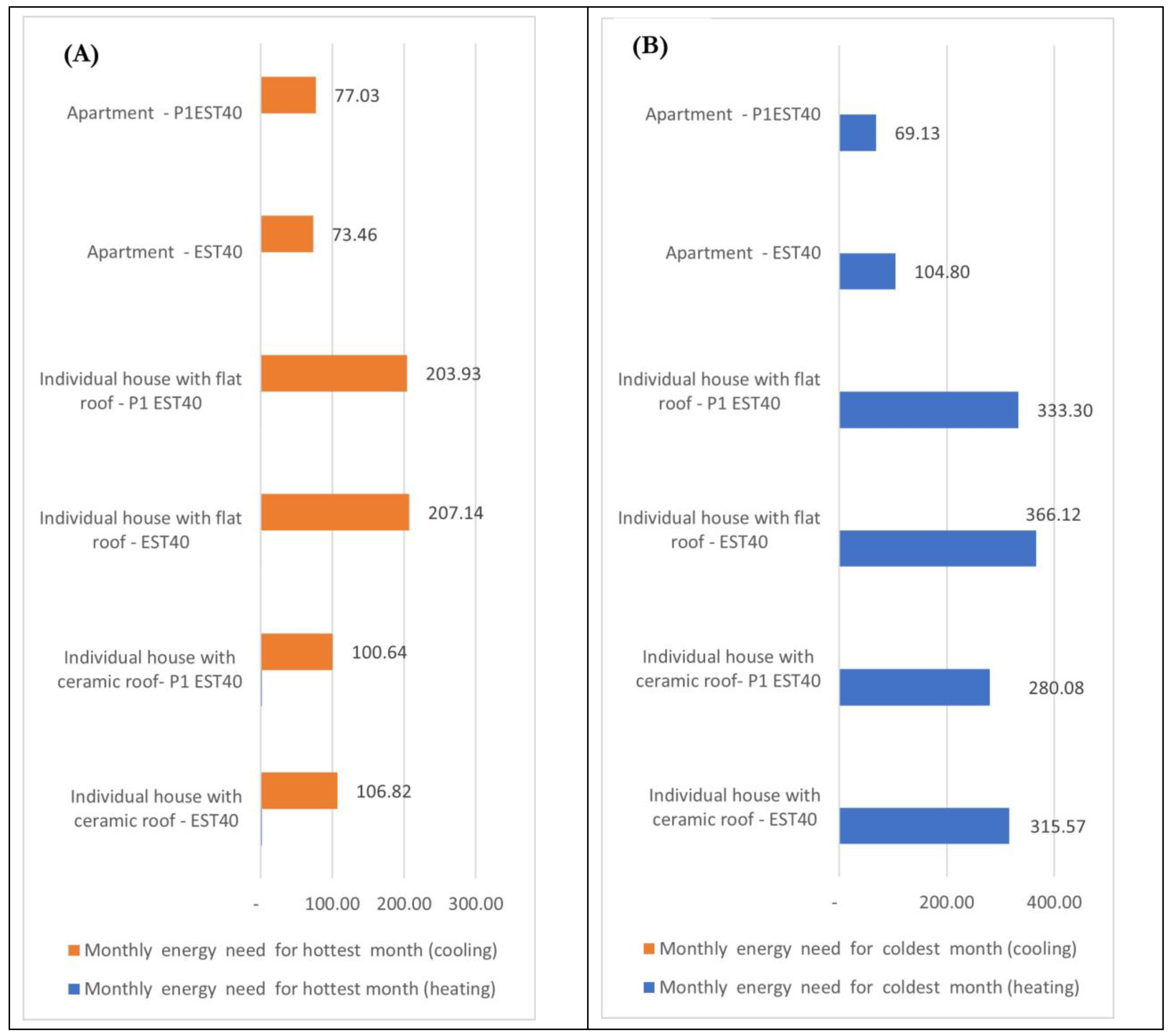
The results obtained using the software EnergyPlus are presented as average monthly consumption values to maintain comfort temperatures, defined between 18 °C and 26 °C. Figure 11A,B shows the monthly energy used in the months of higher heating consumption—July—and higher consumption related to cooling—February—in Curitiba. The house with a flat roof presented the highest consumption, an expected situation considering its high thermal transmittance. The house with a ceramic roof had lower consumption values than the previous one, and the apartment presented the lowest consumption. It is of note that the apartment typology was configured with south walls and a part of the east wall as adiabatic, in addition to the ceiling and floor. This configuration showed a greater similarity with the cases of apartments in condominiums. Ceramic roofs present lower transmittance than flat roofs. In this case, lower energy consumption was also expected.
Regarding another relevant detail, changing geometry from the EST 40 block to the P1 EST 40 block provided savings on heating consumption that, in the long term, may be significant. In the case of the highest heating consumption month, July, the reductions obtained by the block change in the house typology with a ceramic roof, house with a flat roof, and apartment were 11.2%, 9.0%, and 34.0%, respectively. Concerning the significant difference of the last case, it is emphasized that heat exchange occurs predominantly through external walls. It is inferred, therefore, that in this case, the thermal properties of the block presented greater influence. In the case of energy for cooling, there was no significant difference in geometry change. This behavior is connected to the configuration mode adopted for opening doors and windows, considered open at temperatures above 18 °C between 7 am and 12 am.
When observing results for Fortaleza—a city with high humidity and higher average temperatures than Curitiba, which do not usually reach 18 °C—the reduction in cooling consumption was of little relevance, as shown in Figure 12. It can be inferred that the effect of the change is not as relevant due to the procedure for opening doors and windows.
The energy analysis did not simulate HVAC systems configured in EnergyPlus software.
The energy savings results represent total thermal energy required for cooling or heating to comfort temperature. Due to the presented results, it can be inferred that new blocks show a potential to obtain energy savings and better thermal comfort when compared to traditional masonry units.

5. Conclusions

A new geometry of clay blocks was obtained from changes to a commercial reference model. Considering the presented results, there was an improvement in thermal properties without significant additions to the manufacturing material.
The suggested geometry has a simple configuration, formed by several rectangular voids in the longitudinal direction of the wall, with alternating geometry. When simulating two prototypes, this configuration led to reductions of 35.6% and 36.1% in transmittance, compared to the EST-40 reference masonry unit. Regarding the EST 60 reference unit, the reductions obtained were 31.7% and 32%, respectively.
In the case of energy simulation performed using EnergyPlus software, in a housing project used as a reference and for the Brazilian cities of Curitiba and Fortaleza, some improvement in energy consumption was observed with an altered block, P1 EST 40. Significant energy reduction was observed during the winter period for the city of Curitiba. In Fortaleza—a city with higher temperature averages—and during the summer period of Curitiba, there were no significant energy savings. It is possible that this effect occurs due to the heat values maintained by the specification and configuration of opening schedules for windows and doors, which are expected to be open when the temperature is above 18 °C. Regarding the typologies used, it was observed that the greatest percentage of savings occurred in the apartment. In this case, the walls are the main mechanisms of heat transfer, a situation where the reduction of block transmittance gains greater impact. In turn, in a house with a flat roof whose heat transfer occurs largely through the ceiling, the effect of changing the type of block during winter is minor.
One limitation of the Brazilian context is that structural masonry blocks have larger voids that are often used as reinforcements through grout filling, or for the passage of installations. This constraint can be overcome using complementary blocks, from a block family close to the reference model. Finally, it should be noted that the suggested blocks have the potential to be applied or even improved. For this purpose, understanding the effect of block thermal properties on the thermal comfort of buildings is essential.
The findings in this study are important for discussing block geometry improvement regarding energy efficiency in the Brazilian context. In addition, this study draws some general research recommendations and scope for future work:
  • Development of masonry block systems (common and complementary blocks) that can achieve better thermal resistance without significant hollow ratio variation.
  • Development of architectural typologies that allow, associated with these new blocks, greater energy efficiency in the warmer months.
  • Evaluation of the impact of changes in the blocks on their mechanical characteristics.
  • Energy consumption and internal temperatures simulation with different occupation patterns and with the use of HVAC systems.

Author Contributions

Conceptualization, H.S. and I.A.G.; methodology, H.S.; software, I.A.G.; validation, I.A.G., H.S., and A.B.; formal analysis, H.S.; investigation, I.A.G.; resources, I.A.G. and H.S.; data curation, I.A.G.; writing—original draft preparation, I.A.G.; writing—review and editing, I.A.G., H.S., and A.B.; visualization, A.B.; supervision, H.S. and A.B.; project administration, H.S.; funding acquisition, H.S. All authors have read and agreed to the published version of the manuscript.

Funding

This work was financially supported by: Base Funding-UIDB/04708/2020 of the CONSTRUCT-Instituto de I&D em Estruturas e Construções-funded by national funds through the FCT/MCTES (PIDDAC).

Data Availability Statement

The data that support the findings of this study are available from the corresponding author, I.A.G., upon reasonable request.

Acknowledgments

The authors acknowledge the software simulation support provided by civil engineer Rui Sousa.

Conflicts of Interest

The authors declare no conflict of interest.

References

  1. IEA. Electricity Information: Overview; IEA: Paris, France, 2021. [Google Scholar]
  2. ISO 7730:2005; Ergonomics of the Thermal Environment: Analytical Determination and Interpretation of Thermal Comfort Using Calculation of the PMV and PPD Indices and Local Thermal Comfort Criteria. ISO: Geneva, Switzerland, 2005.
  3. ANSI/ASHRAE Standard 55-2010; ASHRAE Thermal Environmental Conditions for Human Occupancy. American Society of Heating, Refrigerating and Air-Conditioning Engineers, Inc.: Peachtree Corners, GA, USA, 2010; Volume 2.
  4. ABNT.NBR 15220; Desempenho Térmico de Edificações. Parte 1: Definições, Símbolos e Unidades. Associação Brasileira de Normas Técnicas: São Paulo, Brasil, 2005.
  5. ABNT.NBR 15220; Desempenho Térmico de Edificações—Parte 2: Métodos de Cálculo Da Transmitância Térmica, Da Capacidade Térmica, Do Atraso Térmico e Do Fator Solar de Elementos e Componentes de Edificações. Associação Brasileira de Normas Técnicas: São Paulo, Brasil, 2008.
  6. ABNT.NBR 15575; Edificações Habitacionais—Desempenho Parte 1: Requisitos Gerais. Associação Brasileira de Normas Técnicas: São Paulo, Brasil, 2021.
  7. Turgut, P.; Yesilata, B. Physico-Mechanical and Thermal Performances of Newly Developed Rubber-Added Bricks. Energy Build. 2008, 40, 679–688. [Google Scholar] [CrossRef]
  8. Krstić, H.; Miličević, I.; Markulak, D.; Domazetović, M. Thermal Performance Assessment of a Wall Made of Lightweight Concrete Blocks with Recycled Brick and Ground Polystyrene. Buildings 2021, 11, 584. [Google Scholar] [CrossRef]
  9. Sutcu, M.; Del Coz Díaz, J.J.; Álvarez Rabanal, F.P.; Gencel, O.; Akkurt, S. Thermal Performance Optimization of Hollow Clay Bricks Made up of Paper Waste. Energy Build. 2014, 75, 96–108. [Google Scholar] [CrossRef] [Green Version]
  10. Sutcu, M. Influence of Expanded Vermiculite on Physical Properties and Thermal Conductivity of Clay Bricks. Ceram. Int. 2015, 41, 2819–2827. [Google Scholar] [CrossRef]
  11. Koçyiğit, F. Thermo-Physical and Mechanical Properties of Clay Bricks Produced for Energy Saving. Int. J. Thermophys. 2022, 43, 18. [Google Scholar] [CrossRef]
  12. Kočí, V.; Bažantová, Z.; Černý, R. Computational Analysis of Thermal Performance of a Passive Family House Built of Hollow Clay Bricks. Energy Build. 2014, 76, 211–218. [Google Scholar] [CrossRef]
  13. Sousa, H.; Sousa, R.; Sousa, L. Influence of Enclosure Masonry Walls on Energy Consumption of Buildings. In Proceedings of the Brick and Block Masonry: Trends, Innovations and Challenges: Proceedings of the 16th Inter-national Brick and Block Masonry Conference (IBMAC 2016), Padova, Italy, 26–30 June 2016; p. 405.
  14. Sousa, H.; Sousa, F.; Sousa, R.M.; Silva, L.C.; Sousa, G.N. Thermal Performance of Light Blocks in a Mediterranean Climate. Rev. Int. De Métodos Numéricos Para Cálculo Y Diseño En Ing. 2020, 36, 13. [Google Scholar] [CrossRef] [Green Version]
  15. Cheng, L.; Zhuang, C.; Li, S.; Huang, G.; Zhang, H.; Gan, F.; Xu, N.; Hou, S. Thermal Performance Optimization Simulation Study of a Passive Solar House with a Light Steel Structure and Phase Change Walls. Energies 2023, 16, 3725. [Google Scholar] [CrossRef]
  16. Ahmad, A.; Al-Hadhrami, L. Thermal Performance and Economic Assessment of Masonry Bricks. Therm. Sci. 2009, 13, 221–232. [Google Scholar] [CrossRef]
  17. Morales, M.P.; Juárez, M.C.; Muñoz, P.; Gómez, J.A. Study of the Geometry of a Voided Clay Brick Using Non-Rectangular Perforations to Optimise Its Thermal Properties. Energy Build. 2011, 43, 2494–2498. [Google Scholar] [CrossRef]
  18. Morales, M.P.; Juárez, M.C.; López-Ochoa, L.M.; Doménech, J. Study of the Geometry of a Voided Clay Brick Using Rectangular Perforations to Optimize Its Thermal Properties. Appl. Therm. Eng. 2011, 31, 2063–2065. [Google Scholar] [CrossRef] [Green Version]
  19. Sousa, H.; Sousa, R. Sensibility Analysis of the Thermal Resistance of Masonry through Numerical Simulations of Laboratory Tests. In Proceedings of the 9th International Masonry Conference, Guimarães, Portugal, 7–9 July 2014. [Google Scholar]
  20. Cuce, P.M.; Cuce, E.; Sudhakar, K. A Systematic Review of Thermal Insulation Performance of Hollow Bricks as a Function of Hollow Geometry. Int. J. Ambient. Energy 2022, 43, 4406–4415. [Google Scholar] [CrossRef]
  21. Cuce, E.; Cuce, P.M.; Besir, A.B. Improving Thermal Resistance of Lightweight Concrete Hollow Bricks: A Numerical Optimisation Research for a Typical Masonry Unit. J. Energy Syst. 2020, 4, 121–144. [Google Scholar] [CrossRef]
  22. Pinterić, M. Heat Transfer in Building Components. Build. Phys. 2021, 71–116. [Google Scholar] [CrossRef]
  23. ISO. ISO 6946; Building Components and Building Elements—Thermal Resistance and Thermal Transmittance—Calculation. International Organization for Standardization: Geneva, Switzerland, 1996.
  24. Ismaiel, M.; Chen, Y.; Cruz-Noguez, C.; Hagel, M. Thermal Resistance of Masonry Walls: A Literature Review on Influence Factors, Evaluation, and Improvement. J. Build. Phys. 2022, 45, 528–567. [Google Scholar] [CrossRef]
  25. EN 1745; Masonry and Masonry Products—Methods for Determining Thermal Properties. CEN: Brussels, Belgium, 2012.
  26. Al-Tamimi, A.S.; Al-Osta, M.A.; Al-Amoudi, O.S.B.; Ben-Mansour, R. Effect of Geometry of Holes on Heat Transfer of Concrete Masonry Bricks Using Numerical Analysis. Arab. J. Sci. Eng. 2017, 42, 3733–3749. [Google Scholar] [CrossRef]
  27. Dias, A.; Ferraz, E.; Sousa, H.; Sousa, L.; Sousa, R.; Lourenço, P.; Vasconcelos, P.; Medeiros, P. Development of Ceramic Block for a Sustainable Construction. In Proceedings of the Sustainability of Constructions—Integrated Approach to Life-Time, Dresden, Germany, 6–7 October 2008. [Google Scholar]
  28. ABNT.ABNT 15270; Componentes Cerâmicos—Blocos e Tijolos Para Alvenaria—Parte 1: Requisitos. Associação Brasileira de Normas Técnicas: São Paulo, Brasil, 2017.
  29. ABAQUS Abaqus User’s Manual Version 2019; Dassault Systèmes Simulia Corp.: Providence, RI, USA, 2019.
  30. Energyplus QuickStart—Welcome to the Energy Plus Quick Start Guide! Available online: https://energyplus.net/quick-start (accessed on 11 July 2022).
  31. Crawley, D.B.; Lawrie, L.K.; Winkelmann, F.C.; Buhl, W.F.; Huang, Y.J.; Pedersen, C.O.; Strand, R.K.; Liesen, R.J.; Fisher, D.E.; Witte, M.J.; et al. EnergyPlus: Creating a New-Generation Building Energy Simulation Program. Energy Build. 2001, 33, 319–331. [Google Scholar] [CrossRef]
  32. Schaefer, A.; Ghisi, E. Method for Obtaining Reference Buildings. Energy Build. 2016, 128, 660–672. [Google Scholar] [CrossRef]
  33. ASHRAE ANSI/ASHRAE Standard 169-2013; Climatic Data for Building Design Standards. ASHRAE: Peachtree Corners, GA, USA, 2013; Volume 8400.
Figure 1. (A) Commercial block class EST40; (B) commercial block class EST60.
Buildings 13 01594 g001
Figure 2. Geometry used as a reference, and alternative geometries for class EST40.
Buildings 13 01594 g002
Figure 3. Geometry used as a reference, and alternative geometries for class EST60.
Buildings 13 01594 g003
Figure 4. Assembly in Abaqus.
Buildings 13 01594 g004
Figure 5. Heat flux through the masonry unit in Abaqus/CAE.
Buildings 13 01594 g005
Figure 6. (A) Reference housing plan; (B) prospective façades of the housing unit.
Buildings 13 01594 g006
Figure 7. Room occupancy pattern.
Buildings 13 01594 g007
Figure 8. Electrical equipment use pattern.
Buildings 13 01594 g008
Figure 9. Artificial lighting use pattern.
Buildings 13 01594 g009
Figure 10. Window opening operation pattern.
Buildings 13 01594 g010
Figure 11. Monthly energy (KWh/month) for Curitiba: (A) February; (B) August.
Buildings 13 01594 g011
Figure 12. Monthly energy (KWh/month) for Fortaleza: (A) June; (B) December.
Buildings 13 01594 g012
Table 1. How to increase thermal resistance according to the related parameters in masonry unit geometry.
Parameter that influences thermal resistanceHow to increase thermal resistance
Number of void rowsIncrease the number of void rows [18,19,26].
Void thickness in the block sectionIncrease the thickness of the void, based on the standard ISO 6946 [23], to improve thermal resistance up to a limit value that depends on the void format.
Web width in the direction of the heat flowReduce the thickness of internal web walls [19,26].
Staggered or ‘in-line’ voidsAvoid thermal bridges in the block by arranging void perforations in quincunx [18]. For blocks with the same proportion of voids, the use of a staggered arrangement for rectangular holes has a considerable effect [26].
Void shapeModify the vertical holes of rectangular shapes to a rumbroid or rhomboid shape, which reduced thermal transmittance in simulation studies by finite elements performed by [27] and [17]. For blocks with the same proportion of voids, rectangular void shapes achieved more efficient results than circular ones [26].
Hollow ratioIncrease hollow ratio (HR), which tends to significantly decrease heat transfer from the outside to the inner side of the block [26].
Unit lengthIncrease unit length [19].
Thermal bridge in the vertical joint regionProlong hole perforations in the tongue and grooved area, to avoid a tongue and groove thermal bridge [17].
Mortar distribution in the jointsUse thin-layer mortar joints [19].
Use discontinuous horizontal joints, although no significant increase is expected when the ratio between the length of mortar filling and the block width is less than 0.4 [19].
Use dry vertical joints or partially filled mortar joints with mechanical locking (voids must be placed near joints to reduce heat flow) [19].
Table 2. Block properties (source: supplier catalogue).
Block ModelSize
(mm)
Weight
(kg)
Mechanical Resistance
(MPa)
Prism Resistance with Mortar of 4.0 (MPa)Net Area/Gross Area (Percentage of Voids)
(%)
U Value
(Thermal Transmittance) (2.5 cm Mortar Layer + Masonry Unit + 2.0 cm Mortar Layer) (W/m2·K)
EST40140 × 190 × 2904.904.02.533Not reported
EST60140 × 190 × 2906.107.03.5412.1
Table 3. Masonry unit dimensions.
ModelExternal Dimensions
(cm)
Net Area/Gross Area
(%)
Shell/Web Thickness
(mm)
EST4014 × 19 × 29 cm337 and 9/6
P1-EST4014 × 19 × 29 cm357/6
P2-EST4014 × 19 × 29 cm357/6
EST6014 × 19 × 29 cm419/8
P1-EST6014 × 19 × 29 cm428/7
P2-EST6014 × 19 × 29 cm428/7
Table 4. Weather conditions summary.
FeaturesCuritibaFortaleza
Climate zone according to [33]3A0A
Latitude−49.18°−3.78°
Longitude−25.52°−38.53°
Elevation (m)91025.0
Dry Bulb Temperature (DBT) average (°C)16.626.5
Wet Bulb Temperature (WBT) average (°C)14.723.4
Relative Humidity (RH) average85%78%
Wind speed (m/s)3.23.8
Table 5. Main characteristics of the construction systems.
Construction elementsLayersThickness (m)Conductivity λ(W/(m·K))Density (kg/m3)Cp J/kg·KU (W/(m2·K))
Concrete0.11.1524001000
FloorsMortar subfloor0.031.15200010008.32
Ceramic tile0.00751.052000920
Mortar0.0251.1520001000
External and internal walls (EST 40 block)Clay block0.140.4506889322.82
Coating mortar0.0251.1520001000
Mortar0.0251.1520001000
External and internal walls (P1 EST 40 block)Clay block0.140.2907239321.90
Coating mortar0.0251.1520001000
Roof, made with a slope layer of ceramic tiles and a horizontal reinforced concrete slab (beam and block system—only for house example)Ceramic tile0.011.052000920
Air gap (R = 0.21 m2·k/W)variable---3.80
Concrete0.051.1524001000
Flat roof—concrete waterproofingConcrete0.11.1524001000
Bitumen sheet (waterproofing)----8.85
Plastering mortar0.031.1520001000
Table 6. Main thermal properties of walls.
Masonry Unit ModelNet Area/Gross Area (Block)
(%)
U Masonry Unit
(W/m2·K)
Reduction in
U Masonry Unit
(%)
Thermal Resistance
(m2·K/W)
U Wall
(W/m2·K)
Reduction
(U Wall)
(%)
EST 40333.212-0.3111.921-
P1 EST 40352.06735.60.4841.44324.9
P2 EST 40352.05436.10.4871.43725.2
EST 60413.398-0.2941.987-
P1 EST 60422.32131.70.4311.56221.3
P2 EST 60422.31032.00.4331.55821.6
Disclaimer/Publisher’s Note: The statements, opinions and data contained in all publications are solely those of the individual author(s) and contributor(s) and not of MDPI and/or the editor(s). MDPI and/or the editor(s) disclaim responsibility for any injury to people or property resulting from any ideas, methods, instructions or products referred to in the content.